Binsfeld Engineering TX10K TorqueTrak 10K-S Torque Telemetry System User Manual
Binsfeld Engineering Inc TorqueTrak 10K-S Torque Telemetry System Users Manual
Users Manual

TorqueTrak 10K-S
Torque Telemetry System
User’s Guide
86950091
- 1 -
Table of Contents
System Overview 3
System Components 4
Features and Controls 5
RX10K Receiver 5
Figure 1: Front view of the RX10K 5
Figure 2: Rear panel of the RX10K (beta units) 6
TX10K-S Transmitter 11
Figure 3: TX10K-S Transmitter 11
RM10K Remote Control 13
Figure 4: RM10K Remote Control 13
Operating Procedure 17
Field Testing 17
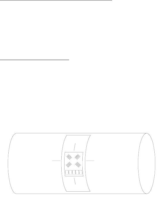
Figure 5: Typical installation on shaft Error! Bookmark
not defined.
Bench Testing 19
Calibration 21
Warranty and Service Information 22
Appendix A: ToqueTrak 10K-S Specifications 23
Appendix B: Calibration Calculations 28
B1: Torque on Round Shafts 29
B2: Axial Strain on Round Shafts 32
B3: Single Grid (1/4 Bridge) 35
Appendix C: Error Codes and Troubleshooting 38
Appendix D: Strain Gage Application 39
- 2 -
FCC Rules Part 15: Computing Devices
This equipment has been tested and found to comply with the
limits for a Class B digital device, pursuant to part 15 of the FCC
Rules.
The user is cautioned that changes and modifications made to
the equipment without the express approval of the manufacturer
could void the user’s authority to operate this equipment.
Operation is subject to the following two conditions: (1) this
device may not cause interference, and (2) this device must
accept any interference that may cause undesired operation of
the device.
Product Safety
The user assumes all risk and liability for the installation and
operation of this equipment. Each application presents its own
hazards. Typically, certain system components are strapped to
a rotating shaft. If sufficient care is not taken to properly secure
these components or accessories connected to them, they can
be flung from the shaft, causing damage to the components or to
property or persons in the vicinity.
- 3 -
System Overview
The TorqueTrak 10K-S Torque Telemetry System utilizes proven
digital RF technology to transmit a single data signal (most
typically from a strain gage) a distance of 20 feet or more
depending on the environment. Up to 16 systems can operate
simultaneously on independent channels without interference.
The system, comprised of three main components, was
designed with many user-friendly features:
RX10K Receiver
Stable 500Hz frequency response
Selectable gain, offset, polarity and channel settings
Digital data (RS-232) and analog voltage output signals
Multiple level, selectable low pass output filtering
LCD display and keypad for easy user interface
TX10K-S Transmitter
High signal-to-noise ratio for excellent resolution
Low temperature coefficient for accuracy from -25 to 85°C
Wide power supply input range from 7 to 18VDC
Power Standby mode to extend battery life
Status Indicator light to assist in troubleshooting
Reinforced housing fits securely on any size shaft
Circuit is fully encapsulated and shielded from EMI/RFI
RM10K Remote Control (for TX10K-S Transmitter)
Change Transmitter setup without tools or removal from shaft
Infrared signal can transmit up to 20 feet
Handheld, easy to use
The TorqueTrak 10K-S is a robust, precision strain measurement
instrument ideal for short-term data collection and diagnostic
testing. It is designed to withstand harsh field conditions with
ease-of-use in mind.

- 4 -
System Components
A standard TorqueTrak 10K-S Torque Telemetry System
includes the following items:
TX10K-S Transmitter
Transmitter Antenna
RX10K Receiver
Receiver Antenna Element
Receiver Antenna Magnetic Base with 25ft Cable
DB9, M-F, RS-232, shielded, 5ft Cable
110VAC-12VDC or 220VAC-12VDC Wall Plug Transformer
RM10K Remote Control
BH10K-9V Battery Holder
BH10K-9V Cover Screws with vibration-resistant coating (2)
BS900 Bridge Simulator
9V Lithium Batteries (2)
9V Battery Connector
5ft 2-Conductor Power Cable
10ft 4-Conductor Ribbon Cable
Butyl Rubber Sheet
1 Roll of 1” Strapping Tape
Screwdriver
3/32” Hex Wrench
TT10K-S User’s Guide
TT10K Equipment Case

- 5 -
Features and Controls
RX10K Receiver
The RX10K Receiver features a simple keypad on the front
panel for user configuration and adjustment. A two-line display
indicates the operational status of the RX10K. The RX10K
conveys the signal received from the TX10K-S Transmitter in
three ways: 1) as text and graphics on the display, 2) as an
analog voltage signal, and 3) as a digital data signal.
The top line of the RX10K display indicates the average level of
the transmitted signal in numerical form on the left and in
graphical form on the right (Figure 1). The numeric value
corresponds to the Voltage Output signal in millivolts. For
example, an output signal of +8.450V would be displayed as
“+08450”. The bar graph provides a visual representation of the
output signal level. Each position on the bar graph represents
approximately 2V. Both the numerical and graphical indicators
are averages of the received signal level over a time period of
about 0.2 seconds.
Figure 1: Front view of the RX10K
When an operational error is detected, the top line of the display
alternates between the corresponding error code and the actual
signal. See Appendix C for a complete list of error codes.
+08450 -_____0___█_+
Rx Ch: 1 ==========
- 6 -
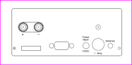
The RX10K rear panel has an On/Off Power switch, a jack for
12VDC Power Input, a Fuse housing, a connector for attaching
the Receiver Antenna, binding posts for the analog Voltage
Output, and a Com (DB9) connector for the digital data signal.
The analog Voltage Output signal has a nominal range of
±10VDC and a maximum range of ±12VDC. The digital data
signal is an RS-232 type signal for input to a PC “Com” port.
See Appendix A for the pin out and protocol.
Figure 2: Rear panel of the RX10K (beta units)
CAUTION: The Voltage Output and digital output (Com) share a
common or ground connection. Pin 5 of the Com (DB9)
connector and the negative (-) side of the Voltage Output are
electrically connected. It is recommended to connect only one of
these outputs to an external device at any given time. If both
outputs are used, a possible "ground loop" problem may result.
A ground loop might cause noise or errors in the Voltage Output
signal or even result in damage to the RX10K. An exception to
this rule exists when one of the two external devices accepting
the analog or digital output signal is “floating” or not externally
connected, such as a battery-operated voltmeter or a laptop
powered by batteries.
Com
Fuse
On
Power
Off
SN:
Voltage
Output
Binsfeld Engineering Inc. Maple City, MI U.S.A. (+1) 231-334-4383

- 7 -
User Parameter Selection and Adjustment
The RX10K Receiver has seven user-configurable parameters.
The parameter name and value are shown on the lower line of
the display. Parameters are selected by scrolling through the
parameter menu using the SELECT ◄► (left and right) arrow
keys. The value of that parameter is adjusted using the
ADJUST ▲▼ (up and down) arrow keys. The parameter name
is displayed on the left side and the value on the right. A
description of the parameter screens and possible settings
follow.
Channel
The Channel parameter allows the user to change the receiving
RF channel to match the RF channel of the TX10K-S. There are
16 RF channels. Appendix A contains a table listing the RF
channels and their corresponding frequencies. Along with the
channel selection value, a bar graph indicating the relative RF
signal strength being received is displayed. The more “=” units,
the better the signal strength (ten is maximum).
Input
The Input parameter allows the user to simulate certain inputs
from the TX10K-S. These can be used to check the operation
and settings of the RX10K, even without a transmitter. The
possible values are listed below:
Input Description
Transmitter The TX10K-S signal is the input (normal
operating mode)
+FS Positive Full Scale input is simulated
Zero Zero level signal input is simulated
-FS Negative Full Scale input is simulated
+FS/2 Positive half scale input is simulated
-FS/2 Negative half scale input is simulated
+FS/4 Positive quarter scale input is simulated
-FS/4 Negative quarter scale input is simulated
+00328 -_____█_____+
Rx Ch: 1 ==========
+00328 -_____█_____+
Input: Transmitter

- 8 -
Filter
The Filter parameter allows the user to change the bandwidth of
the output signal. It functions as a low pass filter, meaning
frequencies above the selected value are attenuated. This
allows the user to reduce the amount of high frequency data on
the output signal (i.e., reduce noise) and effectively average the
output value. Selectable values are 500, 250, 120, 60, 30, 15, 8,
4, 1 Hz.
NOTE: Changing the Filter settings also changes the reception
error rate detection threshold. This means that using a lower
Filter setting may improve data integrity in an electrically noisy
environment (where RF interference is present).
Input AutoZero
The Input AutoZero parameter provides an easy way to
compensate the output for any offset from the gage or sensor.
When turned On ("Input AutoZero: On"), the existing input from
the TX10K-S becomes the input zero. Before adjusting the Gain,
apply the AutoZero to the input signal. In this way, the zero (0V)
output will not change when the Gain setting is adjusted. When
the AutoZero is off ("Input AutoZero: Off"), no offset correction is
applied to the output signal.
To turn the AutoZero On, press and hold the ADJUST ▲ key for
2 seconds. To turn the AutoZero Off, press and hold the
ADJUST ▼ key for 2 seconds. In order for AutoZero to properly
zero the output, the displayed output number must be stable.
Switching the Filter to a lower frequency setting may help
stabilize the signal to enable an effective AutoZero. The Filter
may then be returned to its original setting for normal operation.
The AutoZero function will not work properly if there are 1) too
many “Tx→Rx Data” errors, 2) the signal from the TX10K-S is
over or under range, or 3) the Input parameter is not set to
“Transmitter”.
+00328 -_____█_____+
Filter: 500Hz
+00000 -_____█_____+
Input AutoZero: 0n

- 9 -
Polarity
The Polarity parameter allows the user to change the polarity of
the output signal.
Gain
The Gain parameter allows the user to adjust the gain or scale
factor applied to the input signal and is reflected in the display
output, the Voltage Output signal, and the digital (RS-232) output
signal. This allows the user to scale the output signal. The
Transmitter Gain is displayed on the left ("Gain T:02000
S:02000") and is changed using the RM10K Remote Control.
The System Gain is shown on the right ("Gain T:02000
S:02000") and is the parameter adjusted on the RX10K.
The System Gain represents the product of the Transmitter Gain
and Receiver Gain. The System Gain can be adjusted from 25%
to 400% of the Transmitter Gain (i.e., a Receiver Gain of ¼ to 4).
Equation 1:
Equation 2:
Output Offset
The Output Offset allows the user to adjust the offset or “move
the zero” of the output from the RX10K. The adjustment value
displayed on the right is the actual output offset value in
millivolts. The adjustment range is from –12000mV to
+12000mV (±12V), meaning the zero can be moved anywhere
within the output range.
+00000 -_____█_____+
Polarity: Positive
+00000 -_____█_____+
Gain T:02000 S:02000
+00000 -_____█_____+
0utput 0ffset: +00000
Transmitter
Gain
Receiver
Gain
System
Gain
=
x
Transmitter
Input
Voltage (V)
System
Gain
RX10K
Voltage
Output (V)
= x

- 10 -
Just like the Gain parameter, this adjustment affects the display
output, the Voltage Output signal, and the digital (RS-232) output
signal. The Output Offset value is applied to the signal after the
Gain adjustment; therefore, the Gain adjustment may affect the
zero output signal.
User Default
The RX10K parameters can be returned to their default settings.
This is accomplished by holding down the ADJUST ▲ key while
powering up the RX10K. The default values are listed below.
Default Description
Rx Ch 1
Input Transmitter
Filter 500Hz
Input AutoZero Off
Polarity Positive
Gain T=S
Output Offset 0
Signal Processing
It may be helpful to understand the order in which the data signal
is processed by the RX10K. The signal received from the
TX10K-S is processed as follows:
1. Receive signal from TX10K-S
2. Check for errors and display if any detected
3. Check for Simulated signal and apply if enabled
4. Apply Filter
5. Apply AutoZero
6. Apply Polarity
7. Apply Gain
8. Apply Output Offset
9. Send signal to display, voltage output, and digital output
- 11 -
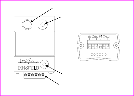
TX10K-S Transmitter
The TX10K-S Transmitter is encased in a tough nylon housing
that incorporates a V-groove on the bottom for improved axial
shaft alignment and an indentation on the top to guide strapping
tape installation. The TX10K-S also features a Status Indicator
light, an Infrared Receiver lens, a connector to accept the
Transmitter Antenna, and a screw terminal block for making
power and sensor input connections.
Figure 3: TX10K-S Transmitter
The TX10K-S can be configured even while it is installed and in
operation using the RM10K Remote Control. The TX10K-S has
sixteen RF Channel settings and six Gain settings (500, 1000,
2000, 4000, 8000, and 16000). It can send low and high
reference signals to the RX10K: internal precision shunt resistors
simulate strain values that can be used to check calibration (refer
to Appendix A for exact specifications). During use, make
certain the Infrared Receiver lens remains unobstructed so that
data can be received from the RM10K Remote Control. The
TX10K-S will operate at short distances from the Receiver
Antenna without the Transmitter Antenna installed if space
around the shaft is limited.
A
ntenna Connecto
r
Infrared Receiver
Status Indicator Light
Screw Terminal Block

- 12 -
Status Indicator Light
When the TX10K-S is powered up, it cycles through a startup
sequence. It transmits four reference signals (the low and high
strain values, positive and negative) and the green Status
Indicator light on the TX10K-S flashes. Once the Status
Indicator is on solid, it is in normal operating mode (transmitting
actual data from the sensor). An error is indicated when the light
is flashing, flickering or off as described below.
Indication TX10K-S Status
Off continuously No power applied; power
polarity is reversed; battery is
dead; or the transmitter is in
Standby mode.
One flash off for ½ second A Gain or Channel command
has been received from the
RM10K Remote Control.
Another flash off for ½ second The Gain or Channel command
has been carried out.
NOTE: If there is only one flash
when changing Gain or
Channel, then the high or low
limit has been reached and
cannot change any further in
that direction.
Fast flash (7 Hz) The input signal to the TX10K-S
is out of range. Reducing the
Gain will increase the input
range and may eliminate this
problem. NOTE: If the out-of-
range condition is of a short
duration, there may only be one
or two flashes.
Slow flash (2 Hz) One of the References (shunts)
is enabled. NOTE: If a signal
out of range condition occurs
while the Reference is enabled,
the light will indicate the out of
range condition (fast flash).
- 13 -
Flicker off once every second The power input voltage is
either too high or too low.
NOTE: Improper operation or
damage to the transmitter can
occur if operated outside its
specified power input voltage
range.
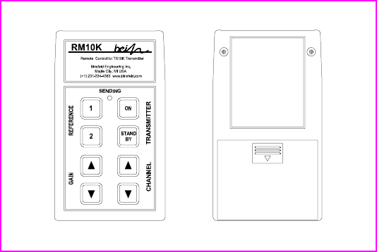
RM10K Remote Control
The handheld RM10K Remote Control allows the user to
configure the TX10K-S Transmitter even while it is installed and
in operation. The RM10K keypad operates similar to a common
TV remote control, emitting an infrared signal through the
window on the front of the unit. Simply point the RM10K at the
Infrared Receiver on the TX10K-S and press the proper key to
change the configuration. Both the Infrared Receiver lens and
the window on the front of the RM10K need to be kept clean in
order to function properly.
Figure 4: RM10K Remote Control

- 14 -
Battery Installation
Slide the battery access cover on the back of the RM10K
enclosure in the direction of the arrow to open. Remove the old
battery if present. Install a new 9V battery and slide the cover
back into place.
Operational Distance Settings
Typically, the RM10K needs to be within a few inches of the
TX10K-S for the signal to be received. This normal (low infrared
power) mode is intended to reduce the possibility of inadvertently
changing the configuration of the TX10K-S by accidentally
pressing a key on the RM10K. It also reduces the chance of
changing the configuration of other transmitters in a multiple-
transmitter installation.
The RM10K also has a high infrared power mode. This mode is
useful when access to the TX10K-S is difficult or dangerous.
Line-of-sight distances of 20 feet or more are possible. The
infrared signal will reflect off of bright or shiny surfaces, making
non-line-of-sight operation possible in some situations.
To enable the high infrared power mode, first press and release
the TRANSMITTER ON key and then press the desired function
key. When the TRANSMITTER ON key is pressed, the green
SENDING light on the RM10K will come on for about 3 seconds.
The desired function key must be pressed within this 3-second
timeframe; otherwise the RM10K will revert back to normal (low
infrared power) mode. To send the ON command in high power
mode, press the TRANSMITTER ON key twice.
The Infrared Receiver on the TX10K-S has an automatic gain
control. Under bright light, it will become less sensitive, and the
operational distance will be decreased. If the TX10K-S is not
receiving commands from the RM10K, try shading the Infrared
Receiver from direct, bright light.
RM10K Functions
A summary of each of the RM10K key functions and indicator
light operation appears below.
TRANSMITTER ON
Brings the TX10K-S out of Standby mode or temporarily enables
high infrared power mode.
- 15 -
TRANSMITTER STANDBY
Switches the TX10K-S into a low-power Standby mode to
conserve the battery. No signal is transmitted while in Standby
mode. The Status Indicator light on the TX10K-S turns off. The
TX10K-S ignores all commands from the RM10K except
TRANSMITTER ON. Disconnecting and reconnecting the 9V
battery or activating TRANSMITTER ON brings the TX10K-S out
of Standby mode.
REFERENCE 1
Activates the Reference 1 input signal or shunt (positive low
value simulated strain) on the TX10K-S for 5 seconds. If this key
is held down, the Reference will stay activated. If the key is
pressed again within the 5 seconds, the Reference will remain
activated for another 5 seconds.
REFERENCE 2
Operation is the same as Reference 1, but a higher shunt value
is activated.
GAIN ▲
Increases the gain setting of the TX10K-S. If the Transmitter
Gain is already at the maximum value, the Status Indicator on
the TX10K-S will flash only once, indicating the command was
received but not carried out.
GAIN ▼
Decreases the gain setting of the TX10K-S. If the gain is already
at the minimum value, the Status Indicator on the TX10K-S will
flash only once, indicating the command was received but not
carried out.
CHANNEL ▲
Increases the RF channel of the TX10K-S. If the channel is
already at the maximum value, the Status Indicator on the
TX10K-S will flash only once, indicating the command was
received but not carried out.
CHANNEL ▼
Decreases the RF channel of the TX10K-S. If the channel is
already at the minimum value, the Status Indicator on the
TX10K-S will flash only once, indicating the command was
received but not carried out.

- 16 -
SENDING Light
The SENDING light will come on for about 1 second when a key
is pressed. This indicates the RM10K is sending a signal. It is
not an indication that the TX10K-S has received the signal. The
Status Indicator on the TX10K-S or the display on the RX10K
can be monitored to confirm successful command transmission.
If the SENDING light flashes after a key is pressed, the battery in
the RM10K is low and should be replaced. If the SENDING light
does not come on at all after a key is pressed, the battery is
dead and needs to be replaced.
As mentioned in the previous section, the SENDING light will
stay on for about 3 seconds after the TRANSMITTER ON key
has been pressed. This indicates the RM10K is in high power
mode, and any command sent during the next 3 seconds will be
at the high infrared power level.
Multiple TX10K-S Transmitters
When working with multiple TX10K-S Transmitters in close
proximity, the Infrared Receivers may be intentionally covered
with an opaque object in order to eliminate an inadvertent
configuration change to an adjacent TX10K-S. Also, removing
power (disconnecting the battery) or putting the TX10K-S in
standby mode will prevent the RM10K from changing the
configuration of a transmitter.
- 17 -
Operating Procedure
The TorqueTrak 10K-S System is designed for ease of use. The
procedure for a typical setup on a shaft for obtaining torque
measurements is detailed in the Field Testing section below.
It is recommended that the user bench test the instrument to
become familiar with the various operational features prior to
conducting tests in the field. The BS900 Bridge Simulator and 9V
Battery Connector have been provided for this purpose. See the
Bench Testing section for details.
Field Testing
Although the settings of the TX10K-S can be changed during
operation of the system, it is best to determine the appropriate
Transmitter Gain setting for a given application prior to
installation. Refer to Appendix B for the relevant calculations.
1. Attach sensor or strain gage to the shaft (or other surface)
where the desired strain will be measured. (Refer to
Appendix D for instructions on strain gage application.)
2. Remove cover from BH10K-9V Battery Housing. Snap fresh
9V battery onto snaps and place into BH10K-9V. Secure
cover with screws with re-usable vibration-resistant coating.
CAUTION: Substituting screws without vibration-resistant
coating or failure to properly tighten screws could result in
loosening of the screws during rotation, and components
could be flung from the shaft.
NOTE: The BH10K-9V is most useful when testing extends
beyond the life of the battery, allowing replacement of the
battery without removal from the shaft. Alternatively, the 9V
Battery Connector can be used. In this case, skip step 4.
3. Screw Transmitter Antenna onto TX10K-S Transmitter.
Secure TX10K-S and BH10K-9V (or battery) to shaft using
strapping tape. Align V-groove on bottom axially with shaft
and tape across indentation in top. Do not cover TX10K-S
Infrared Receiver or Status Indicator. Alternatively, hose
- 18 -
clamps, machined collars, or other mounting devices may be
used but avoid excessive compression.
CAUTION: Be certain all components are securely fastened
to moving surfaces. Avoid the risk of being struck by an
improperly secured object flung from the machine by
standing clear during operation!
4. Cut an appropriate length of 2-conductor power cable (red &
black twisted pair) and strip and tin ends. Connect red wire
to +B on BH10K-9V and to +B on TX10K-S and black wire to
-B on BH10K-9V and to -B on TX10K-S. The Status
Indicator light should come on solid. Secure to shaft.
NOTE: If testing will not begin for some time, use the RM10K
Remote Control to put the TX10K-S in Standby mode to
save battery life. The Status Indicator light will turn off.
5. Cut an appropriate length of 4-conductor ribbon cable (as
short as practical to avoid unwanted electrical noise) and
strip and tin ends. Solder to gage per Appendix D or gage
manufacturer’s specification and make appropriate
connections to the TX10K-S terminals. Secure loose cable
to shaft.
6. Connect Receiver Antenna to Antenna connector on the
rear panel of the RX10K Receiver. Position magnetic-mount
antenna with element installed near the TX10K-S, typically
within 10 feet.
7. Insert connector on AC/DC adapter into Power Input jack on
the RX10K rear panel. Plug adapter into appropriate AC
power source (i.e., wall socket). Flip the RX10K power
switch to On while holding down the ADJUST ▲ key.
NOTE: This resets the RX10K parameters to their default
settings. Simply turn On without holding any keys if
previously set parameter configurations are desired.
8. Turn on the TX10K-S with the RM10K (if needed). Confirm
that Status Indicator light is on solid. Slowly scroll through
each RX10K channel until it matches TX10K-S channel
setting (top line will quit flashing and bottom line will show
the RF signal strength). Change both units to desired
channel and verify adequate signal strength. If possible,
- 19 -
rotate the TX10K-S through complete range of motion to
verify strong signal reception in all orientations.
9. Scroll RX10K display to Gain parameter screen. Use the
RM10K to configure the Transmitter Gain to the appropriate
level.
10. Scroll RX10K display to Input AutoZero parameter screen.
Apply AutoZero with no load on the shaft to zero-out any
initial gage offset. Press and hold ADJUST ▲ key for 2
seconds until bottom line reads “Input AutoZero: On”.
AutoZero can be reset by turning off and then on again.
NOTE: Once AutoZero is activated, the initial offset is
subtracted from the Full Scale output. Consequently, the
Full Scale range of the system will be reduced by this offset
amount. For example, if the initial offset is 1.6V then the Full
Scale output of the system will be 8.4V after AutoZero is set.
If before activating AutoZero there is an initial offset of more
than 50% of Full Scale, it may be necessary to 1) use a
lower Transmitter Gain setting, 2) apply a shunt resistor to
balance the gage, or 3) replace the strain gage. For further
assistance, contact Binsfeld Engineering Inc.
11. Scroll RX10K display to Filter parameter screen. Set the
Filter to the desired level.
12. Scroll RX10K display to Gain parameter screen. Set the
System Gain to calibrate output based on gain calculations
as demonstrated in Appendix B. Check calibration by using
the RM10K to command the TX10K-S to transmit
REFERENCE 1 and/or 2 to the RX10K or use the Input
parameter settings.
13. Connect appropriate recording device to either the analog
Voltage Output terminals or digital Com (DB9) connector.
14. The System is now ready to record data.
Bench Testing
1. Connect Receiver Antenna to Antenna connector on the
rear panel of the RX10K Receiver. Position magnetic-mount
antenna with element installed near the TX10K-S.
- 20 -
Insert connector on AC/DC adapter into Power Input jack on
the RX10K rear panel. Plug adapter into appropriate AC
power source (i.e., wall socket). Flip the RX10K power
switch to On while holding down the ADJUST ▲ key.
2. Attach 9V Battery Connector to TX10K-S Transmitter (red to
+B, black to –B). Attach BS900 to TX10K-S terminals +/- E
and +/- S correctly correspond with pins on BS900. Clip 9V
battery to connector.
3. Slowly scroll through each RX10K channel until it matches
TX10K-S channel setting (top line will quit flashing and
bottom line will show the RF signal strength). Change both
units to desired channel and verify adequate signal strength.
(To configure TX10K-S settings, use the RM10K Remote
Control.)
4. Scroll RX10K display to Gain parameter screen. Use the
RM10K to configure the Transmitter Gain to 4000 (“Gain
T:04000 S:04000”).
5. Scroll RX10K display to Input AutoZero parameter screen.
Apply AutoZero with BS900 in center or zero (0) position.
Press and hold ADJUST ▲ key for 2 seconds until bottom
line reads “Input AutoZero: On”.
6. Switch BS900 to the positive (+) position. RX10K output
should be close to +2V (“+02000”) and the bar graph
indicator should move one segment to the right of zero (“0”).
7. Switch BS900 to the negative (–) position. RX10K output
should be close to -2V (“-02000”) and the bar graph indicator
should move one segment to the left of zero (“0”).
8. Use the RM10K to command the TX10K-S to transmit
REFERENCE 1. RX10K output should be close to +2V
(“+02000”) and the bar graph indicator should move one
segment to the right of zero (“0”).

- 21 -
Calibration
The TorqueTrak 10K-S System is calibrated prior to shipping
using instruments traceable to the United States National
Institute of Standards and Technology (NIST). Calibration can be
checked at any time with a NIST traceable reference such as a
calibrated voltmeter with sufficient (millivolt) resolution.
To verify calibration of the RX10K Receiver:
1. Insert connector on AC/DC adapter into Power Input jack on
the RX10K rear panel (refer to Figure 2 on page 6). Plug
adapter into appropriate AC power source (i.e., wall socket).
Flip the RX10K power switch to On while holding down the
ADJUST ▲ key.
2. Allow the RX10K to warm up for 15 minutes.
3. Connect a calibrated, high-accuracy voltmeter to the
Voltage Output terminals.
4. Scroll RX10K display to Input parameter screen. Press the
ADJUST ▲ key to scroll through the simulated inputs and
check the outputs.
Input Output
+FS 10.000 ± .010 VDC
Zero 0.000 ± .005 VDC
-FS -10.000 ± .010 VDC
+FS/2 5.000 ± .005 VDC
-FS/2 -5.000 ± .005 VDC
+FS/4 2.500 ± .005 VDC
-FS/4 -2.500 ± .005 VDC
It is recommended that the system be checked for calibration
annually. If found to be out of specification, it can be returned to
Binsfeld Engineering Inc. for calibration for a nominal fee
($100.00, price subject to change).

- 22 -
Warranty and Service Information
LIMITED WARRANTY
Binsfeld Engineering Inc. warrants that its products will be free
from defective material and workmanship for a period of one
year from the date of delivery to the original purchaser and that
its products will conform to specifications and standards
published by Binsfeld Engineering Inc. Upon evaluation by
Binsfeld Engineering Inc., any product found to be defective will
be replaced or repaired at the sole discretion of Binsfeld
Engineering Inc. Our warranty is limited to the foregoing, and
does not apply to fuses, paint, or any equipment, which in
Binsfeld Engineering’s sole opinion has been subject to misuse,
alteration, or abnormal conditions of operation or handling.
This warranty is exclusive and in lieu of all other warranties,
expressed or implied, including but not limited to any
implied warranty of merchantability or fitness for a
particular purpose or use. Binsfeld Engineering Inc. will not
be liable for any special, indirect, incidental or
consequential damages or loss, whether in contract, tort, or
otherwise.
NOTE (USA only): Some states do not allow limitation of implied warranties, or
the exclusion of incidental or consequential damages so the above limitations or
exclusions may not apply to you. This warranty gives you specific legal rights
and you may have other rights which vary from state to state.
For service please contact Binsfeld Engineering Inc.:
4571 W. MacFarlane
Maple City, MI 49664
Phone: (+1) 231-334-4383
Fax: (+1) 231-334-4903
Internet: www.binsfeld.com
Email: Sales@binsfeld.com

- 23 -
Appendix A: ToqueTrak 10K-S Specifications
TorqueTrak 10K-S Telemetry System
Resolution 14 bits (Full Scale = 16384
points)
Sample Resolution 14 bits
Sample Transmission Rate 2400 Hz
Signal Bandwidth 500 Hz (-3dB) *2
Signal to noise ratio 70 dB (min) *1,*2
Signal delay 4.2 mS (typ) *2
(transmitter input to voltage output)
RF Transmission Distance 20 ft line-of-sight (typ)
RF Channel Frequencies Table
RF
Channel
Frequency
(MHz)
RF
Channel
Frequency
(MHz)
1 902.62 9 914.62
2 904.12 10 916.12
3 905.62 11 917.62
4 907.12 12 919.12
5 908.62 13 920.62
6 910.12 14 922.12
7 911.62 15 923.62
8 913.12 16 925.12
RX10K Receiver
Display 2 line x 20 character high
contrast LCD w/backlight
Power Supply Input 10 to 18 VDC @ 300mA
(max)
Included Power Supply 120 VAC input, 12 Vdc
output @ 500 mA (max)
Optional Power Supply 220 VAC input, 12 Vdc
output @ 500 mA (max)
Gain adjustment 0.25 to 4.0
Output Offset adjustment ±10 V
Antenna input connection SMA
Antenna supplied 3" w/magnetic base and 25'
cable

- 24 -
Operating Temperature Range -20 to 70˚C (-4 to 158˚F)
Size 5.6” x 2.5" x 7.0" (142 mm x
64 mm x 178 mm)
Weight 30 oz (860 grams)
Analog Voltage Output
(electrically isolated from the other inputs and outputs)
Isolation 500 VAC/DC (min)
Connection 5-way binding posts
Nominal Range ±10 V
Maximum Range ±12 V
Offset Error ±0.05 %FS @ 25 ˚C
Offset Temperature Coefficient 15 ppm/˚C
Gain Error ±0.05% @ 25 ˚C ambient
Gain Temperature Coefficient 15 ppm/˚C
Output impedance 50 Ω (max)
Recommended Output Load 100 KΩ (min), 1000 pF
(max)
Digital Output (Com) Specification
The TT10K-S system includes a streaming digital output port on
the rear panel of the RX10K Receiver. This output data is RS-
232 type. A DB-9 male-female cable is supplied for direct
connection to a PC Com port.
Pin out of the DB9 connector on the RX10K
1
2 TXD Data output
3
4
5 GND Ground or common connection
6
7
8
9
PC COM Port Settings
Bits per second 115200
Data bits 8
Parity none
Stop bits 1
Flow control none

- 25 -
Sample Protocol
The output sample rate is 2400 samples per second. There are
4 bytes sent for each sample.
1 Start byte ASCII 'SOH' code (hex 01)
2 Sample data low byte
3 Sample data high byte
4 Stop byte ASCII 'CR' code (hex 0D)
The sample data is sent as a 16 bit signed integer.
Dout = Vin · Asys · 1000
Dout = streaming digital output sample data
Vin = TX10K transmitter voltage input (gage or sensor voltage)
Asys = TT10K system gain factor
Transmission Error Detection Table
Filter Setting Max number of
corrupt samples Out of xx samples
500 Hz 1 5
250 Hz 2 10
120 Hz 4 20
60 Hz 8 40
30 Hz 16 80
15 Hz 32 160
8 Hz 64 320
4 Hz 128 640
2 Hz 256 1280
1 Hz 512 2560
TT10K-S Transmitter
Power Supply Voltage 7 to 18 Vdc
Power Supply Current (transmit mode) 40 mA (nom), 50 mA
(max) *3
Power Supply Current (standby mode) 4 mA (nom), 5 mA
(max)
9V Ultralife Li battery life (transmit mode) 24 hours (est) *3
9V Ultralife Li battery life (standby mode) 240 hours (est)
Excitation Voltage 2.50 VDC (±0.05%,
10ppm/˚C)

- 26 -
Available Output Current 20 mA (max)
Input impedance (+S to –S, shunts off) 1 GΩ (typ)
Input bias current (+S or –S, shunts off) 20 nA (max)
Input voltage range (+S or -S, ref to -E) 0.2 to 3.9 V
Offset Error ±0.1 %FS @ 35˚C
ambient *1
Offset Temperature Coefficient 10 ppm/˚C *1
Gain Error ±0.25% @ 35˚C
ambient *1
Gain Temperature Coefficient 25 ppm/˚C *1
Shunt resistor (Reference 1) 437400 Ω, +/-0.1%,
25 ppm/˚C
Shunt resistor (Reference 2) 87370 Ω,+/-0.1%,
25 ppm/˚C
Simulated torque strain (350 Ω bridge, GF = 2.0)
Shunt resistor (Reference 1) 100 ue
Shunt resistor (Reference 2) 500 ue
Note: TX10K gain levels 500, 1000 and 2000 are calibrated
using shunt resistor Reference 2. Gain levels 4000, 8000 and
16000 are calibrated using shunt resistor Reference 1. All gain
levels are calibrated with a 350Ω bridge.
System Gain (V/V)
Input
Range
Full Scale
Input
(mV) Min Nom Max
1 ±20 125 500 2,000
2 ±10 250 1,000 4,000
3 ±5 500 2,000 8,000
4 ±2.5 1,000 4,000 16,000
5 ±1.25 2,000 8,000 32,000
6 ±0.625 4,000 16,000 64,000
Screw Terminal Connector
1 +B Positive Battery or DC power supply input
2 -B Negative Battery or DC power supply input
3 +E Positive Excitation or voltage output
4 +S Positive Sense or voltage input
5 -S Negative Sense or voltage input
6 -E Negative Excitation voltage output (internally
connected to –B)
- 27 -
Antenna connection Reverse SMA
Antenna supplied 2" w/reverse SMA
G force 3000 G's (max
continuous)
Operating Temperature Range -30 to 85˚C (-22 to
185˚F)
Size 1.00" x 1.61" x 2.47"
(25 mm x 41 mm x 63
mm)
Weight 3 oz (83 grams)
RM10K Remote Control
Power Supply 9 V battery (supplied)
Pulsed infrared frequency 38 KHz
Transmission distance (normal mode) 6 in (typ)
High infrared power mode 20 ft (typ) line of sight
Operating Temperature Range (battery) -20 to 60˚C (-4 to
140°F)
Size 2.6" x 0.9" x 4.4"
(65 mm x 23 mm x
112 mm)
Weight 3 oz (76 grams)
BH10K Battery Holder
Size 1.00" x 1.61" x 2.47"
(25 mm x 41 mm x 63
mm)
Weight 1 oz (38 grams)
Screw Terminal Connector
1 +B Positive Battery output
2 -B Negative Battery output
NOTES:
All specifications subject to change.
*1 Transmitter gain level = 2000
*2 RX10K filter set at 500 Hz
*3 Measured with a 350Ω bridge connected
- 28 -
Appendix B: Calibration Calculations
The equations in this Appendix define the relationship between
the input signal to the TX10K-S Transmitter (typically from a
strain gage) and the Full Scale output voltage of the TorqueTrak
10K-S System. The calculations are based on parameters of the
device being measured (e.g. shaft diameter), sensor parameters
(e.g. gage factor) and Transmitter Gain setting.
Section B1 is specific to torque measurements on round shafts
(full bridge, 4 active arms).
Section B2 applies to axial strain (tension/compression)
measurements on round shafts (full bridge, 2.6 active arms).
Section B3 is for use with a single grid (1/4 bridge).

- 29 -
(VFS)(π)(E)(4)(Do
4-Di
4)
= TFS (N-m)
(VEXC)(GF)(N)(16000)(1+ν)(GXMT)(Do)
B1: Torque on Round Shafts
Step 1: Calculate Full Scale Torque, T FS (ft-lb) that corresponds
to the maximum system output of 10.0V.
For a solid steel shaft, use this simplified equation:
For all other shafts use the more general equation:
Legend of Terms
Di Shaft Inner Diameter (in) (zero for solid shafts)
Do Shaft Outer Diameter (in)
E Modulus of Elasticity (30 x 106 PSI steel)
GF Gage Factor (specified on strain gage package)
GXMT Telemetry Transmitter Gain (user configurable, typical
is 4000 for ±500 microstrain range)
N Number of Active Gages (4 for torque)
TFS Full Scale Torque (ft-lb)
VEXC Bridge Excitation Voltage = 2.5 volts
VFS Full Scale Output of System = 10 volts
ν Poisson’s Ratio (0.30 for steel)
For metric applications with Do and Di in millimeters and TFS in
N-m the general equation is:
Where E= 206.8 x 10³ N/mm2.
(1510.34 x 103 ft-lb/in3)(Do
3)
= TFS (ft-lb)
(GF) (GXMT)
(VFS)(π)(E)(4)(Do
4-Di
4)
= TFS (ft-lb)
(VEXC)(GF)(N)(16)(1+ν)(GXMT)(Do)(12)

- 30 -
Example: Given a solid steel shaft with
Do (shaft diameter, measured) = 2.5 inches
GF (gage factor from gage package) = 2.045
GXMT (TX10K-S gain setting) = 4000
(1510.34 x 103 ft-lb/in3)(2.50 in)3
TFS = = 2,885 ft-lb
(2.045) (4000)
so 10.0 V output from the RX10K indicates 2,885 ft-lb of torque
or 288.5 ft-lb/volt.
Step 2: Trim the Full Scale Output: If desired, the full scale
output voltage of the TX10K can be trimmed so that the
voltage output corresponds to an even round number
torque level, e.g. 100 ft-lb/volt. First, calculate the
trimmed voltage value (VTRIM) that corresponds to the
round number (trimmed) torque level (TTRIM). Note: TTRIM
must be greater than TFS calculated above.
Legend of Terms
TFS Full Scale Torque (ft-lb)
TTRIM Trimmed Torque (ft-lb)
VFS Full Scale Output of System = 10 volts
VTRIM Trimmed Output of System
(TFS)(VFS)
VTRIM =
TTRIM

- 31 -
Example: The full scale torque (TFS) has been calculated to
be 2,885 ft-lb, for 10 volts. However the user would
like to scale the system output to an adjusted
torque (TTRIM) of 4,000 ft-lb for 10 volts. (Note that
TTRIM = 4,000 is greater than TFS = 2,885.)
(2,885 ft-lb)(10 volts)
= V
TRIM = 7.21 volts
(4,000 ft-lb)
Step 3: Adjust the Full Scale Output to equal VTRIM on the
RX10K by adjusting the System Gain (see page 9).
The system is now calibrated so that 4,000 ft-lb equals 10 volts
(i.e. the gain of the system is 400 ft-lb/volt).
In summary:
Before adjusting full scale output:
2,885 ft-lb = 10 volts (288.5 ft-lb/volt)
After adjusting full scale output:
4,000 ft-lb = 10 volts (400 ft-lb/volt)

- 32 -
B2: Axial Strain on Round Shafts
Step 1: Calculate Full Scale Forces P FS (lb) that corresponds to
the maximum system output of 10.0V.
For a solid steel shaft, use this simplified equation:
For all other shafts use the more general equation:
Legend of Terms
Di Shaft Inner Diameter (in) (zero for solid shafts)
Do Shaft Outer Diameter (in)
E Modulus of Elasticity (30 x 106 PSI steel)
GF Gage Factor (specified on strain gage package)
GXMT Telemetry Transmitter Gain (user configurable, typical is
4000 for ±770 microstrain range)
PFS Full Scale Force (tension or compression) (lb)
VEXC Bridge Excitation Voltage = 2.5 volts
VFS Full Scale Output of System = 10 volts
ν Poisson’s Ratio (0.30 for steel)
(VFS)(π)(E)(Do
2-Di
2)
= P
FS
(VEXC)(GF)(2)(1+ν)(GXMT)
(145 x 106 lb/in2)(Do
2)
= PFS
(GF) (GXMT)

- 33 -
Example: Given a solid steel shaft with
D
O (shaft diameter, measured) = 2.25 inches
GF (gage factor from gage package) = 2.045
G
XMT (TX10K-S gain setting) = 4000
(145 x 106 lb/in2)(2.25 in)2
PFS = = 89,736 lb
(2.045) (2000)
so 10.0 V output from the RX10K indicates 89,736 lb of force or
8974 lb/volt.
Step 2: Trim the Full Scale Output: If desired, the full scale
output voltage of the RX10K can be trimmed so that the
voltage output corresponds to an even round number
force level, e.g. 1000 lb/volt. First, calculate the trimmed
voltage value (VTRIM) that corresponds to the round
number (trimmed) force level (PTRIM). Note: PTRIM must be
greater than PFS calculated above.
Legend of Terms
PFS Full Scale Force (lb)
PTRIM Trimmed Force (lb)
VFS Full Scale Output of System = 10 volts
VTRIM Trimmed Output of System
(PFS)(VFS)
VTRIM =
PTRIM

- 34 -
Example: The full scale force (PFS) has been calculated to be
89,736 lb for 10 volts. However the user would like
to scale the system output to an adjusted force
(PTRIM) of 100,000 lb for 10 volts. (Note that PTRIM =
100,000 is greater than PFS = 89,736.)
(89,736 lb)(10 volts)
= VTRIM = 8.97 volts
(100,000 lb)
Step 3: Adjust the Full Scale Output to equal VTRIM on the RX10K
by adjusting the System Gain (see page 9).
The system is now calibrated so that 100,000 lb equals 10 volts
(i.e. the gain of the system is 10,000 lb/volt).
In summary:
Before adjusting full scale output:
89,736 lb = 10 volts (8973 lb/volt)
After adjusting full scale output:
100,000 lb = 10 volts (10,000 lb/volt)

- 35 -
B3: Single Grid (1/4 Bridge)
Step 1: Calculate Full Scale Strain, ε FS (inches/inch) that
corresponds to the maximum system output of 10.0V.
Using the values listed in the table below, this equation reduces
to:
Legend of Terms
εFS Full Scale Strain (inches/inch; 10-6 inches/inch =
1 microstrain)
GF Gage Factor (specified on strain gage package)
GXMT Telemetry Transmitter Gain (user configurable, typical is
4000 for ±2000 microstrain range)
VEXC Bridge Excitation Voltage = 2.5 volts
VFS Full Scale Output of System = 10 volts
(VFS)(4)
= εFS
(VEXC)(GF)(GXMT)
(16)
= εFS
(GF)(GXMT)

- 36 -
Example: GF (gage factor from gage package) = 2.045
G
XMT (TX10K-S gain setting) = 4000
(16)
εFS = = 1956 x 10-6 inches/inch
(2.045)(4000)
so 10.0 V output from the RX10K indicates 1956 microstrain or
196 microstrain/volt.
Step 2: Trim the Full Scale Output: If desired, the full scale
output voltage of the RX10K can be trimmed so that the
voltage output corresponds to an even round number
strain level, e.g. 1000 microstrain/volt. First, calculate the
trimmed voltage value (VTRIM) that corresponds to the
round number (trimmed) strain level (εTRIM). Note: εTRIM
must be greater than εFS calculated above.
Legend of Terms
εFS Full Scale Strain (inches/inch; 10-6 inches/inch =
1 microstrain)
εTRIM Trimmed Strain (inches/inch)
VFS System Output Full Scale = 10 volts
VTRIM Trimmed Voltage Output
(εFS)(VFS)
VTRIM = εTRIM

- 37 -
Example: The full scale strain (εFS) has been calculated to be
1956 microstrain for 10 volts. However the user
would like to scale the system output to an adjusted
strain (εTRIM) of 2000 microstrain for 10 volts. (Note
that εTRIM = 2000 is greater than εFS = 1956.)
(1956 microstrain)(10 volts)
= VTRIM = 9.78 volts
(2000 microstrain)
Step 3: Adjust the Full Scale Output to equal VTRIM on the RX10K
by adjusting the System Gain (see page 9).
The system is now calibrated so that 2000 microstrain equals 10
volts (i.e. the gain of the system is 200 microstrain/volt).
In summary:
Before adjusting full scale output:
1956 microstrain = 10 volts (195.6 microstrain /volt)
After adjusting full scale output:
2000 microstrain = 10 volts (200 microstrain /volt)
- 38 -
Appendix C: Error Codes
Error Displayed Error Detected
Tx Signal UnderRange The input signal to the TX10K-S
is less than the minimum level
Tx Signal OverRange The input signal to the TX10K-S
is greater than the maximum
level
Rx Signal UnderRange The output signal of the RX10K
is less than the minimum level
Rx Signal OverRange The output signal of the RX10K
is greater than the maximum
level
Tx->Rx Data Error The signal from the TX10K-S is
not being received properly by
the RX10K
NOTE: The output signals of the
RX10K will go to negative full
scale (-12000mV)
Tx Power Low Error The power supply voltage level
of the TX10K-S is to low
Tx Power High Error The power supply voltage level
of the TX10K-S
Rx Power Low Error The power supply voltage level
of the RX10K is too low
Rx Power High Error The power supply voltage level
of the RX10K is too high

- 39 -
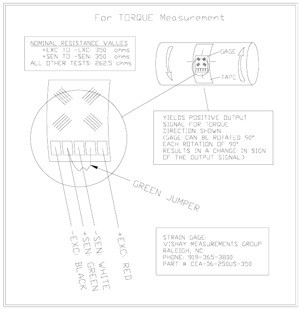
Appendix D: Strain Gage Application
(Also refer to instruction bulletin B-127-12 provided with GAK-2-
200 Strain Gage Application Kit from Vishay Measurements
Group, Inc., Raleigh, NC, 919-365-3800,
www.measurementsgroup.com.)
PREPARING THE SURFACE
1. A 3-inch square area will be used for gaging. Scrape off
any paint or other coatings and inspect shaft for oil
residue. If necessary, use a degreasing solution or
isopropyl alcohol to remove.
2. Rough sand the gaging area with 220 grit paper. Finish
the sanding procedure by wetting the gaging area with
M-Prep Conditioner A and the wetted surface with 400
grit paper provided. Rinse by squirting with M-Prep
Conditioner A. Wipe the area dry with tissue taking
care to wipe in only one direction. Each time you wipe
use a clean area of the tissue to eliminate
contamination.
3. Rinse shaft this time by squirting with M-Prep
Neutralizer 5A. Wipe the gaging area dry with a clean
tissue, wiping in only one direction and using clean area
of tissue with each wipe. Do not allow any solution to dry
on the surface as this may leave a contaminating film
which can reduce bonding. Surface is now prepared for
bonding.
MARKING THE SHAFT FOR GAGE ALIGNMENT
4. The gage needs to be perpendicular to the shaft axis. In
general, this can be accomplished by eye since
misalignment of less than 4 degrees will not generate
significant errors. For higher precision, we recommend
two methods for marking the shaft:
a) Use a machinist square and permanent marker or
scribe for perpendicular and parallel lines; or
b) Cut a strip of graph paper greater than the
circumference of the shaft. Tape it to the shaft while
- 40 -
lining up the edges. Mark desired gage position with
a scribe or permanent marker.
PREPARING THE GAGE FOR MOUNTING
5. Using tweezers, remove one gage from its package.
Using the plastic gage box as a clean surface, place the
gage on it, bonding side down. Take a 6” piece of PCT-
2A Cellophane Tape and place it on the gage and
terminal, centered. Slowly lift the tape at a shallow angle.
You should now have the gage attached to the tape.
POSITIONING THE GAGE
6. Using the small triangles located on the four sides of the
gage, place the taped gage on the shaft, perpendicular
with the shaft axis, aligned with your guide marks. If it
appears to be misaligned, lift one end of tape at a
shallow angle until the assembly is free to realign. Keep
one end of the tape firmly anchored. Repositioning can
be done as the PCT-2A tape will retain its mastic when
removed and therefore not contaminate the gaging area.
Positioning the Gage on the Shaft

- 41 -
7. Gage should now be positioned. Once again, lift the
gage end of the tape at a shallow angle to the surface
until the gage is free of the surface. Continue pulling the
tape until you are approximately 1/8” – 1/4” beyond
gage. Turn the leading edge of the tape under and press
it down, leaving the bonding surface of the gage
exposed.
8. Apply a very thin, uniform coat of M-Bond 200-Catalyst
to the bonding surface of the gage. This will accelerate
the bonding when glue is applied. Very little catalyst is
needed. Lift the brush cap out and wipe excess on lip of
bottle. Use just enough catalyst to wet gage surface.
Before proceeding, allow catalyst to dry at least one
minute under normal ambient conditions of + 75°F and
30-65% relative humidity.
NOTE: The next three steps must be completed in
sequence within 3 – 5 seconds. Read through
instructions before proceeding so there will be no delays.
Have Ready:
M-Bond (Cyanoacrylate) Adhesive
2” – 5” piece of teflon tape
Tissues
MOUNTING THE GAGE
9. Lift the leading edge of the tape and apply a thin bead of
adhesive at the gage end where the tape meets the
shaft. Adhesive should be of thin consistency to allow
even spreading. Extend the line of glue outside the gage
installation area.
10. Holding the tape taut, slowly and firmly press with a
single wiping stroke over the tape using a teflon strip (to
protect your thumb from the adhesive) and a tissue (to
absorb excess adhesive that squeezes out from under
the tape). This will bring the gage back down over the
alignment marks on the gaging area. This forces the
glue line to move up and across the gage area. A very

- 42 -
thin, uniform layer of adhesive is desired for optimum
bond performance.
11. Immediately, using your thumb, apply firm pressure to
the taped gage by rolling your thumb over the gage area.
Hold the pressure for at least one minute. In low
humidity conditions (below 30%) or if ambient
temperature is below + 70° F, pressure application time
may have to be extended to several minutes.
12. Leave the cellophane tape on an additional five minutes
to allow total drying then slowly peel the tape back
directly over itself, holding it close to the shaft while
peeling. This will prevent damage to the gages. It is not
necessary to remove the tape immediately after
installation. It offers some protection for the gaged
surface and may be left until wiring the gage.
WIRING THE GAGE
13. Tin each solder pad with a solder dot. (It is helpful to
polish the solder tabs, e.g. with a fiberglass scratch
brush or mild abrasive, before soldering.) Trim and tin
the ends of the 4-conductor ribbon wire. Solder the lead
wires to the gage by placing the tinned lead onto the
solder dot and pressing it down with the hot soldering
iron. Note: For single-stamp torque gages, a short
jumper is required between solder pads 2 and 4 as
shown in the diagram on the next page
14. Use the rosin solvent to clean excess solder rosin from
the gage after wiring. Brush the gage pads with the
solvent and dab with a clean tissue.
15. Paint the gage area (including the solder pads) with M-
Coat A polyurethane and allow to air dry 15 minutes.
This protects the gage from moisture and dirt. To further
protect the gage, cover with a 1.5 inch square patch of
rubber sheet and a piece of M-Coat FA-2 aluminum
foil tape (optional) then wrap with electrical tape.
- 43 -

- 44 -
Revision History
Rev Date Description
1 02/07 First draft for beta release. Need to create
Troubleshooting steps for App C. App A needs
to be updated and streamlined. Plan to add
bending equations to App B. Need color photo
for cover page and drawing for Figure 5 on page
19 (not included in this version).
This page for BEI reference only
NOT to be included with customer manual