Biolase EPIC-1 Wireless Foot Pedal User Manual
Biolase, Inc. Wireless Foot Pedal
UserManual.wiki
>
Biolase
>
EPIC 1 User Manual
User Manual
Navigation menu
Upload a User Manual
Namespaces
Wiki Guide
HTML
PDF
Info
Views
User Manual
Discussion / Help
Navigation

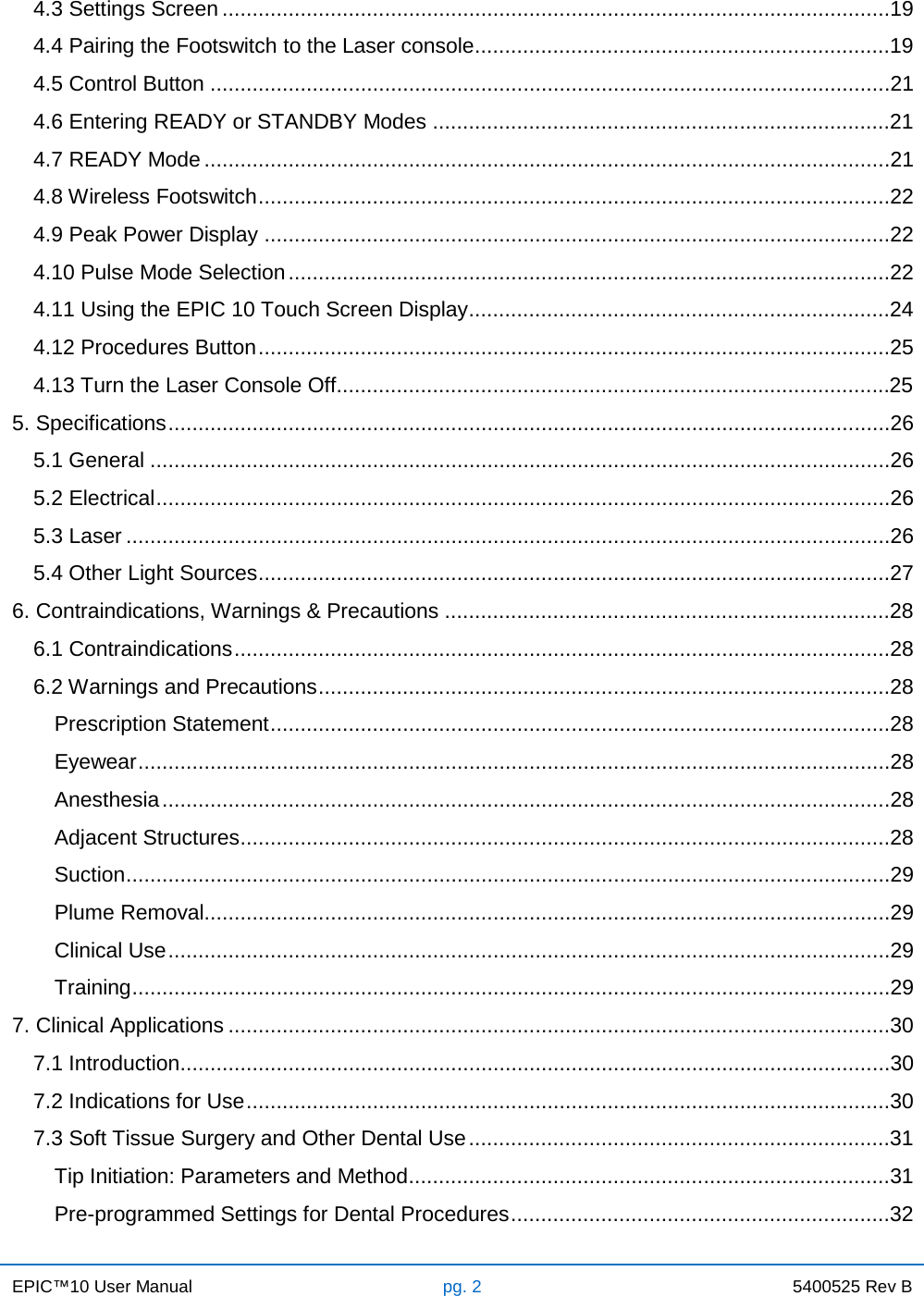
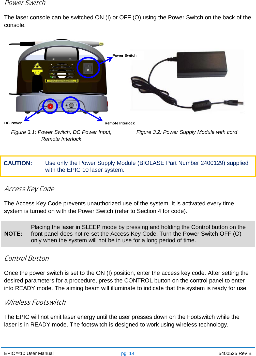
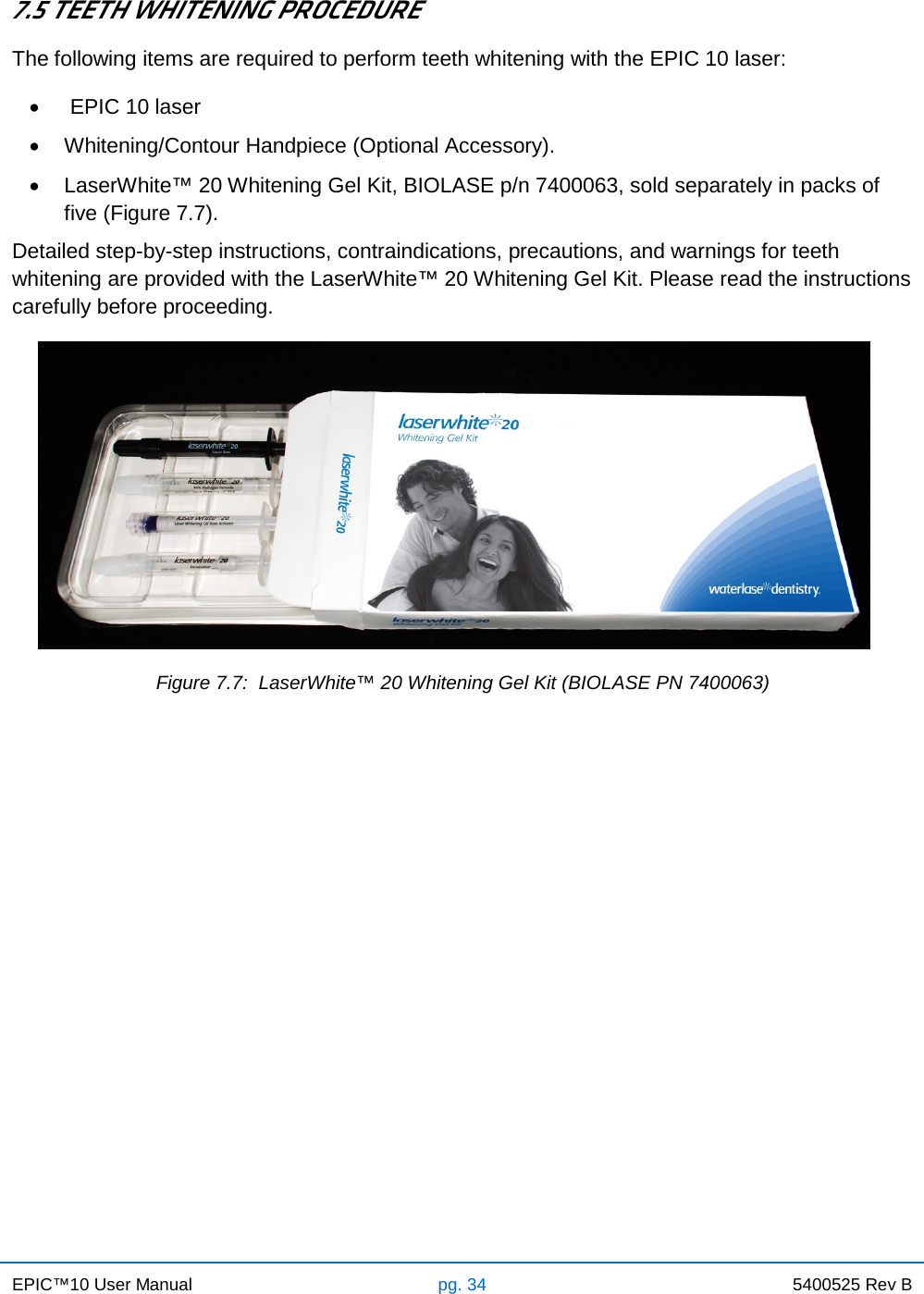
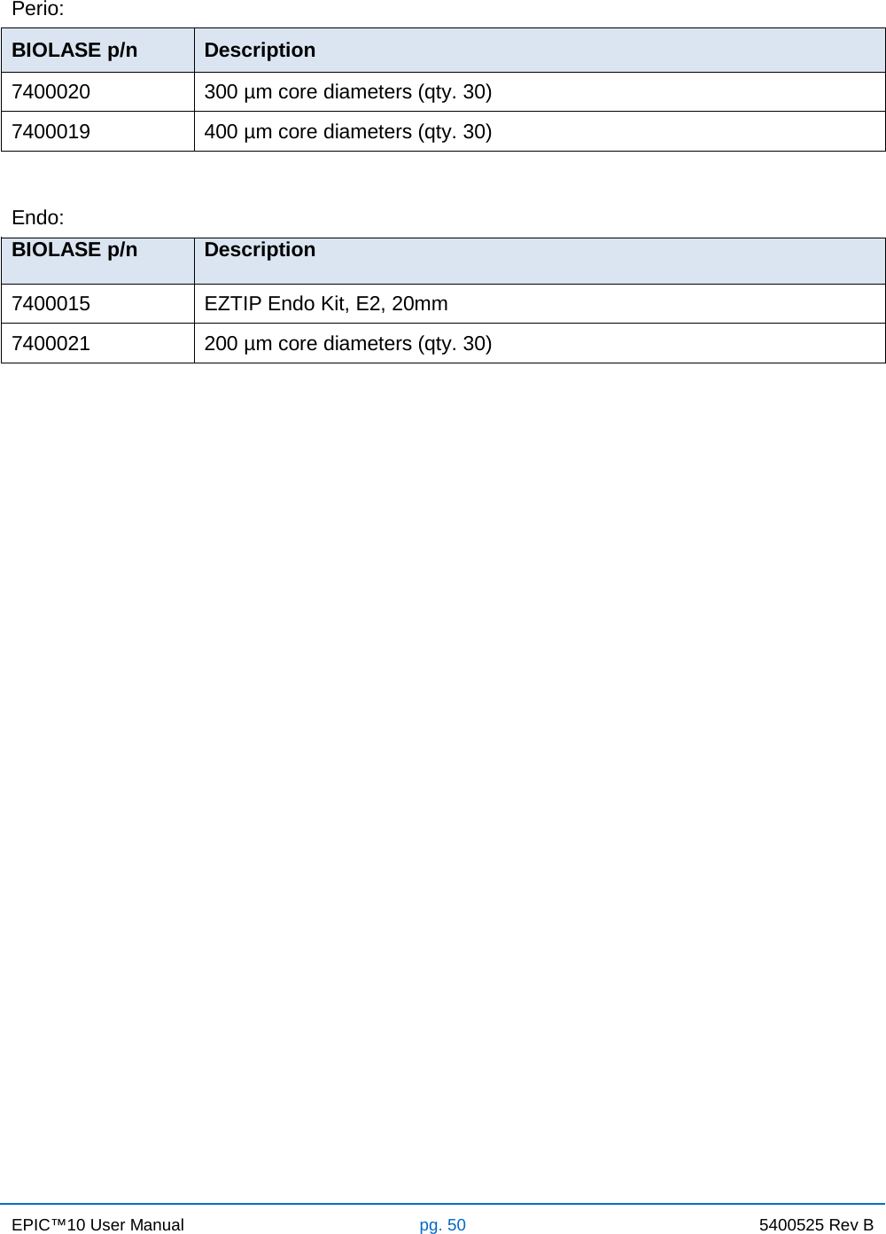
![EPIC™10 User Manual pg. 52 5400525 Rev B GUIDANCE AND MANUFACTURER’S DECLARATION – ELECTROMAGNETIC IMMUNITY (Continued) The model Epic 10 is intended for use in the electromagnetic environment specified below. The customer or the user of the model Epic 10 should assure that it is used in such an environment. Immunity test IEC 60601 test level Continuous level Electromagnetic environment - guidance Conducted RF IEC 61000-4-6 Radiated RF IEC61000-4-3 3 Vrms 150 kHz to 80 GHz 3V/m 80 MHz to 2.5 GHz 3 V 3Vm Portable and mobile RF communications equipment should be used no closer to any part of the model Epic 10, including cables, than the recommended separation distance calculated from the equation applicable to the frequency of the transmitter. Recommended separation distance d = 1.2√P d = 1.2√P 80 MHz to 800 MHz d = 2.3√P 800MHz to 2.5GHZ Wher P is the maximum output power rating of the transmitter in watts (W) according to the transmitter manufacturer and d 8s the recommended separation distance in meters (m). Field strengths from fixed RF transmitters, as determined by an electromagnetic site survey,a should be less than the compliance level in each frequency range.b Interference may occur in the vicinity of equipment marked with the following symbol: NOTE 1 - At 80 MHz and 800 MHz, the higher frequency range applies. NOTE 2 – These guidelines may not apply in all situations. Electromagnetic propagation is affected by absorption and reflection from structures, objects, and people. A. Field strengths from fixed transmitters, such as base stations for radio (cellular/cordless) telephone and land mobile radios, amateur radio, AM and FM radio broadcast and TV broadcast cannot be predicted theoretically with accuracy. To assess the electromagnetic environment due to fixed RF transmitters, an electromagnetic site survey should be considered. If the measured field strength in the location in which the Epic 10 is used exceeds the applicable RF compliance level above, the Epic 10 should be observed to verify normal operation. If abnormal performance is observed, additional measures may be necessary, such as reorienting or relocating the Epic 10. B. Over the frequency range 150 kHz to 80 MHz, field strengths should be less than [V1] V/m.](https://usermanual.wiki/Biolase/EPIC-1/User-Guide-2162290-Page-53.png)
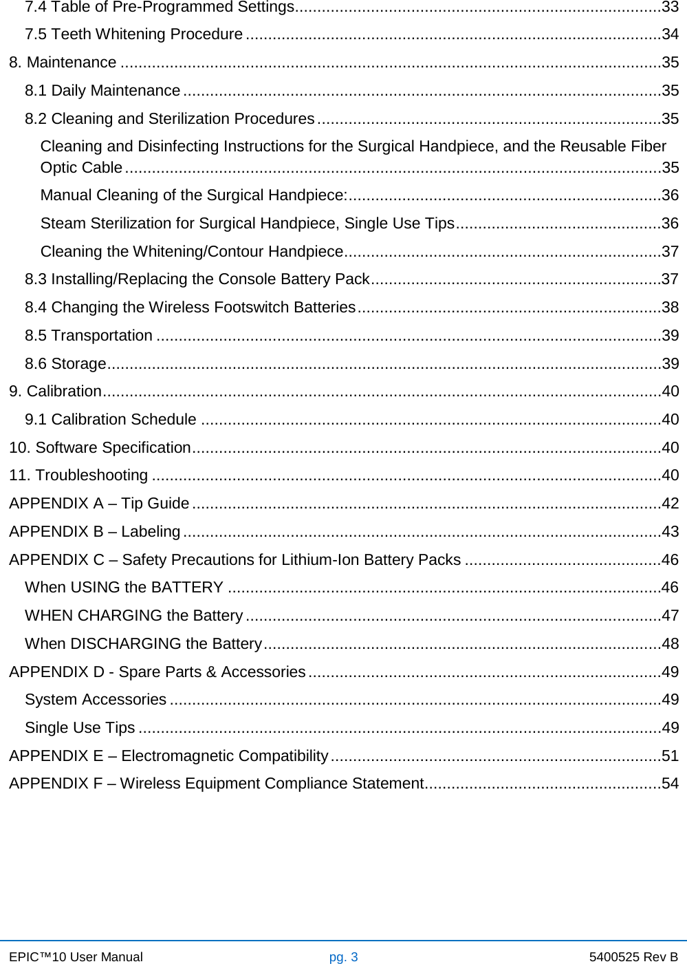
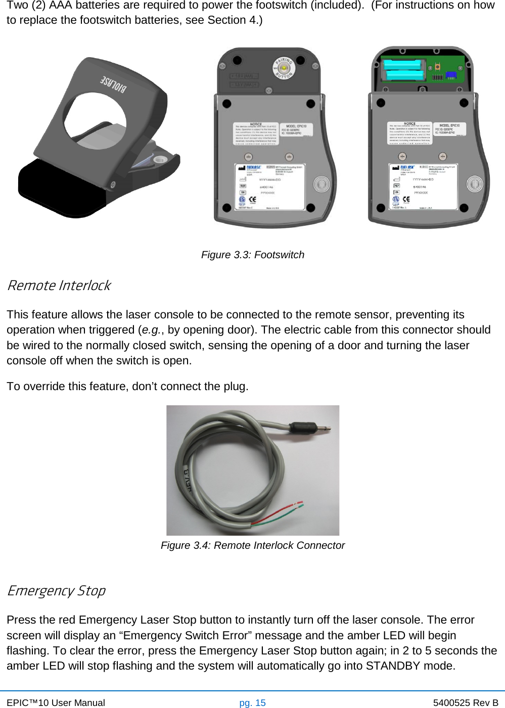
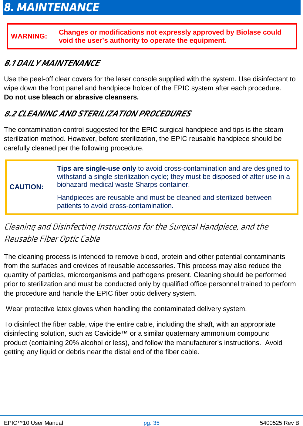
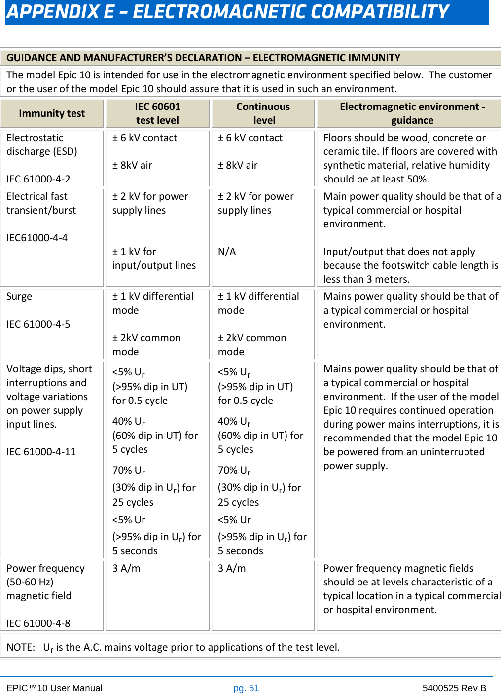
![EPIC™10 User Manual pg. 54 5400525 Rev B APPENDIX F – WIRELESS EQUIPMENT COMPLIANCE STATEMENT This statement applies only to the wireless portion of the device: This equipment has been tested and found to comply with the limits for a Class B digital device, pursuant to part 15 of the FCC Rules. These limits are designed to provide reasonable protection against harmful interference in a residential installation. This equipment generates, uses, and can radiate radio frequency energy and, if not installed and used in accordance with the instructions, may cause harmful interference to radio communications. However, there is no guarantee that interference will not occur in a particular installation. If this equipment does cause harmful interference to radio or television reception, which can be determined by turning the equipment off and on, the user is encouraged to try to correct the interference by one or more of the following measures: • Reorient or relocate the receiving antenna. • Increase the separation between the equipment and receiver. • Connect the equipment into an outlet on a circuit different from that to which the receiver is connected. • Consult the dealer or an experienced radio/TV technician for help. This Class [B] digital apparatus meets all requirements of the Canadian Interference-Causing Equipment Regulations.](https://usermanual.wiki/Biolase/EPIC-1/User-Guide-2162290-Page-55.png)