User Manual
EPIC 10 User Manual P/N 5400525 Rev. B
Founded in 1986, BIOLASE, Inc. specializes in lasers for medicine
and dentistry that feature proprietary and patented technologies for
minimally invasive surgeries, reducing pain and improving clinical
results.
Only BIOLASE combines the leading laser technology – continuously
improved through ongoing clinical R&D and engineering – with
unmatched training, practice integration support and service.
BIOLASE leads the global dental laser market with over 24,000 lasers in
use today and the most complete family of dental lasers – from diode
lasers to the most advanced all-tissue laser, the WaterLase iPlus.
About BIOLASE
BIOLASE, Inc.
4 Cromwell
Irvine, CA 92618 USA
949.361.1200
888.424.6527
biolase.com
© 2013 BIOLASE, Inc. All rights reserved. EPIC, iLase, ezLase, ezTip, LaserWhite, Deep Tissue Handpiece,
ComfortPulse, WaterLase, and WaterLase iPlus are either trademarks or registered trademarks of BIOLASE,
Incorporated in the United States and/or other countries. All other trademarks are property of their registered
owners. Subject to change without notice.
User Manual
EPIC 10 User Manual P/N 5400525 Rev. B
Made in the USA
Conforms to:
AAMI ES60601-1
IEC60601-1
IEC6060-2-22
IEC62366
IEC80601-2-60
IEC60825-1
Certified to:
CSA C22-2 No. 60601-1
5400525 Rev A, User Manual Cover, EPIC 10 Canada.indd 1 12/20/2013 10:24:46 AM

EPIC™10 User Manual
pg. 1
5400525 Rev B
TABLE OF CONTENTS
TABLE OF CONTENTS ............................................................................................................. 1
Introduction ................................................................................................................................ 4
1.Packaging ............................................................................................................................... 5
1.1 System Parts List .............................................................................................................. 5
1.2 Facility Requirements ....................................................................................................... 5
2. Equipment Description ........................................................................................................... 6
2.1 General ............................................................................................................................ 6
2.2 Base Console ................................................................................................................... 6
2.3 Control Panel .................................................................................................................... 6
2.4 Surgical Delivery System .................................................................................................. 7
2.6 Fiber Optic Connection ..................................................................................................... 7
2.7 Single-Use Tips ................................................................................................................ 8
2.8 Surgical Handpiece Assembly .......................................................................................... 8
2.9 Whitening/Contour Handpiece (Optional Accessory) .......................................................11
3. Safety....................................................................................................................................12
3.1 Precautions .....................................................................................................................12
3.2 Safety Instructions ...........................................................................................................12
3.3 Safety Features ...............................................................................................................13
Energy Monitor ..................................................................................................................13
System Monitor ..................................................................................................................13
Power Switch .....................................................................................................................14
Access Key Code ...............................................................................................................14
Control Button ....................................................................................................................14
Wireless Footswitch ...........................................................................................................14
Remote Interlock ................................................................................................................15
Emergency Stop ................................................................................................................15
Functional Display ..............................................................................................................16
3.4 Safety Classification ........................................................................................................16
4. Operation Instructions ...........................................................................................................17
4.1 System setup ...................................................................................................................17
4.2 Operation - Turn on the EPIC 10 Laser ..........................................................................18

EPIC™10 User Manual
pg. 2
5400525 Rev B
4.3 Settings Screen ...............................................................................................................19
4.4 Pairing the Footswitch to the Laser console .....................................................................19
4.5 Control Button .................................................................................................................21
4.6 Entering READY or STANDBY Modes ............................................................................21
4.7 READY Mode ..................................................................................................................21
4.8 Wireless Footswitch .........................................................................................................22
4.9 Peak Power Display ........................................................................................................22
4.10 Pulse Mode Selection ....................................................................................................22
4.11 Using the EPIC 10 Touch Screen Display ......................................................................24
4.12 Procedures Button .........................................................................................................25
4.13 Turn the Laser Console Off............................................................................................25
5. Specifications ........................................................................................................................26
5.1 General ...........................................................................................................................26
5.2 Electrical ..........................................................................................................................26
5.3 Laser ...............................................................................................................................26
5.4 Other Light Sources .........................................................................................................27
6. Contraindications, Warnings & Precautions ..........................................................................28
6.1 Contraindications .............................................................................................................28
6.2 Warnings and Precautions ...............................................................................................28
Prescription Statement .......................................................................................................28
Eyewear .............................................................................................................................28
Anesthesia .........................................................................................................................28
Adjacent Structures ............................................................................................................28
Suction ...............................................................................................................................29
Plume Removal..................................................................................................................29
Clinical Use ........................................................................................................................29
Training ..............................................................................................................................29
7. Clinical Applications ..............................................................................................................30
7.1 Introduction ......................................................................................................................30
7.2 Indications for Use ...........................................................................................................30
7.3 Soft Tissue Surgery and Other Dental Use ......................................................................31
Tip Initiation: Parameters and Method ................................................................................31
Pre-programmed Settings for Dental Procedures ...............................................................32

EPIC™10 User Manual
pg. 3
5400525 Rev B
7.4 Table of Pre-Programmed Settings ..................................................................................33
7.5 Teeth Whitening Procedure .............................................................................................34
8. Maintenance .........................................................................................................................35
8.1 Daily Maintenance ...........................................................................................................35
8.2 Cleaning and Sterilization Procedures .............................................................................35
Cleaning and Disinfecting Instructions for the Surgical Handpiece, and the Reusable Fiber
Optic Cable ........................................................................................................................35
Manual Cleaning of the Surgical Handpiece: ......................................................................36
Steam Sterilization for Surgical Handpiece, Single Use Tips ..............................................36
Cleaning the Whitening/Contour Handpiece .......................................................................37
8.3 Installing/Replacing the Console Battery Pack .................................................................37
8.4 Changing the Wireless Footswitch Batteries ....................................................................38
8.5 Transportation .................................................................................................................39
8.6 Storage ............................................................................................................................39
9. Calibration .............................................................................................................................40
9.1 Calibration Schedule .......................................................................................................40
10. Software Specification .........................................................................................................40
11. Troubleshooting ..................................................................................................................40
APPENDIX A – Tip Guide .........................................................................................................42
APPENDIX B – Labeling ...........................................................................................................43
APPENDIX C – Safety Precautions for Lithium-Ion Battery Packs ............................................46
When USING the BATTERY .................................................................................................46
WHEN CHARGING the Battery .............................................................................................47
When DISCHARGING the Battery .........................................................................................48
APPENDIX D - Spare Parts & Accessories ...............................................................................49
System Accessories ..............................................................................................................49
Single Use Tips .....................................................................................................................49
APPENDIX E – Electromagnetic Compatibility ..........................................................................51
APPENDIX F – Wireless Equipment Compliance Statement .....................................................54

EPIC™10 User Manual
pg. 4
5400525 Rev B
INTRODUCTION
The EPIC™ 10 laser is a surgical and therapeutic device at the cutting edge of technology,
designed for a wide variety of oral soft tissue procedures and dental whitening.
The EPIC™ 10 utilizes a solid state diode as a semiconductor source for invisible infrared
radiation. The energy is delivered to the treatment site via flexible fiber connected at one end to
the laser source and the other end to the Handpiece. Various types of single use, disposable
tips are designed and optimized for different applications. The device is activated by means of
a wireless footswitch.
This is a prescription device that is indicated for professional use only by licensed medical and
dental practitioners. The use of this device requires proper clinical and technical training. This
manual provides instructions for those professionals that have completed the appropriate
training.
When used and maintained properly, the EPIC™ will prove a valuable addition to your practice.
Please contact BIOLASE Customer Service at 1-800-321-6717 for any service needs.
This device must be installed, operated, and maintained according the guidelines of CAN/CSA-
Z386-08 “Laser safety in health care facilities.”

EPIC™10 User Manual
pg. 5
5400525 Rev B
1.PACKAGING
1.1 SYSTEM PARTS LIST
The EPIC 10 laser system (BIOLASE p/n 7400042C) includes the following:
1. Laser Console (lithium ion battery pack already installed)
2. Screen Protectors box (Peel-off clear screen cover - qty. 30)
3. Tips box
4. Surgical Handpiece box (contains two (2) Surgical Handpieces)
5. Three (3) pairs of protective laser eyewear (two (2) pairs of doctor safety glasses,
one (1) pair of darker patient safety glasses)
6. DC power supply and power cord
7. User Manual
8. Welcome Kit (Welcome Letter, BIOLASE store information, Quick Setup Guide,
Product Registration Card, Limited Warranty Information)
9. Laser Warning Sign
10. Tip Initiation Kit
11. Remote Interlock cable
12. Philips-head screwdriver (for installing Footswitch batteries)
13. Footswitch
14. AAA batteries (2)
NOTE:
The laser ships with the lithium ion battery pack already installed.
NOTE:
Use proper care when transporting the unit. Refer to Section 8 in this User
Manual for instructions.
WARNING:
No modification of this equipment is allowed.
1.2 FACILITY REQUIREMENTS
Electrical Supply (100-240V ~):
1.5A, 50/60Hz
Environmental Requirements:
Temperature: 20-25 ºC
Humidity: 15-95%, Non-condensing
EPIC™10 User Manual
pg. 6
5400525 Rev B
2. EQUIPMENT DESCRIPTION
2.1 GENERAL
The EPIC 10 laser system consists of three components:
● Base Console
● Delivery System
● Wireless Footswitch
2.2 BASE CONSOLE
The Console has a display panel (Touch Screen and Control Button) in front. It can be powered
by an external mains power supply or an internal replaceable lithium ion battery pack, 14.4V,
2.9 Ah.
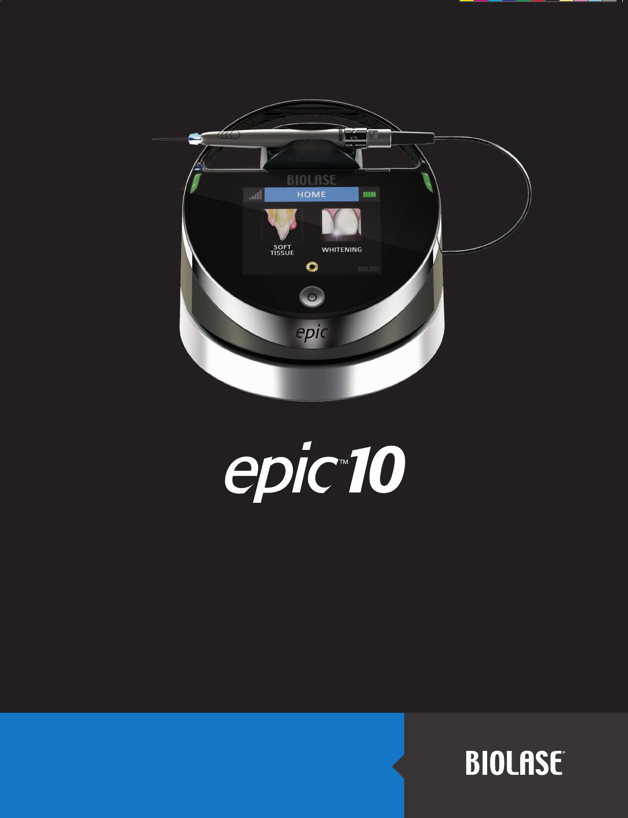
2.3 CONTROL PANEL
ITEM ITEM DESCRIPTION
CONTROL
Button
Turns the controls and display on and
off; places the unit into STANDBY or
READY or SLEEP mode
LED
Indicator
• Amber indicates unit is in
STANDBY mode.
• Green indicates unit is in READY
mode.
• Blinking green indicates the
emission of laser power.
• Blinking blue indicates pairing
between the footswitch and laser
console is active
Figure 2.1: Control Panel (Front View)
LED Indicator
LED Indicator
Control Button

EPIC™10 User Manual
pg. 7
5400525 Rev B
2.4 SURGICAL DELIVERY SYSTEM
NOTE:
All fiber optic cables, handpieces & tips are shipped non-sterile.
The EPIC 10 Re-Useable Delivery System with surgical Handpiece consists of:
• Re-useable Fiber Optic Assembly
• Re-useable Surgical Handpiece (Figures 2.4, 2.5)
• Disposable Tips (See Figures 2.7, 2.8, 2.9, 2.10)
NOTE:
The fiber optic cable is detachable from the console. The handpiece is a re-usable
accessory and will require cleaning and sterilization prior to each patient treatment.
Tips are intended for single-use only and must be disposed of after each patient use.
Proper tip disposal in a biohazard medical waste Sharps container is required. Tips
must be steam sterilized prior to use. For instructions on cleaning and sterilization of
the handpiece and tips refer to Section 8.
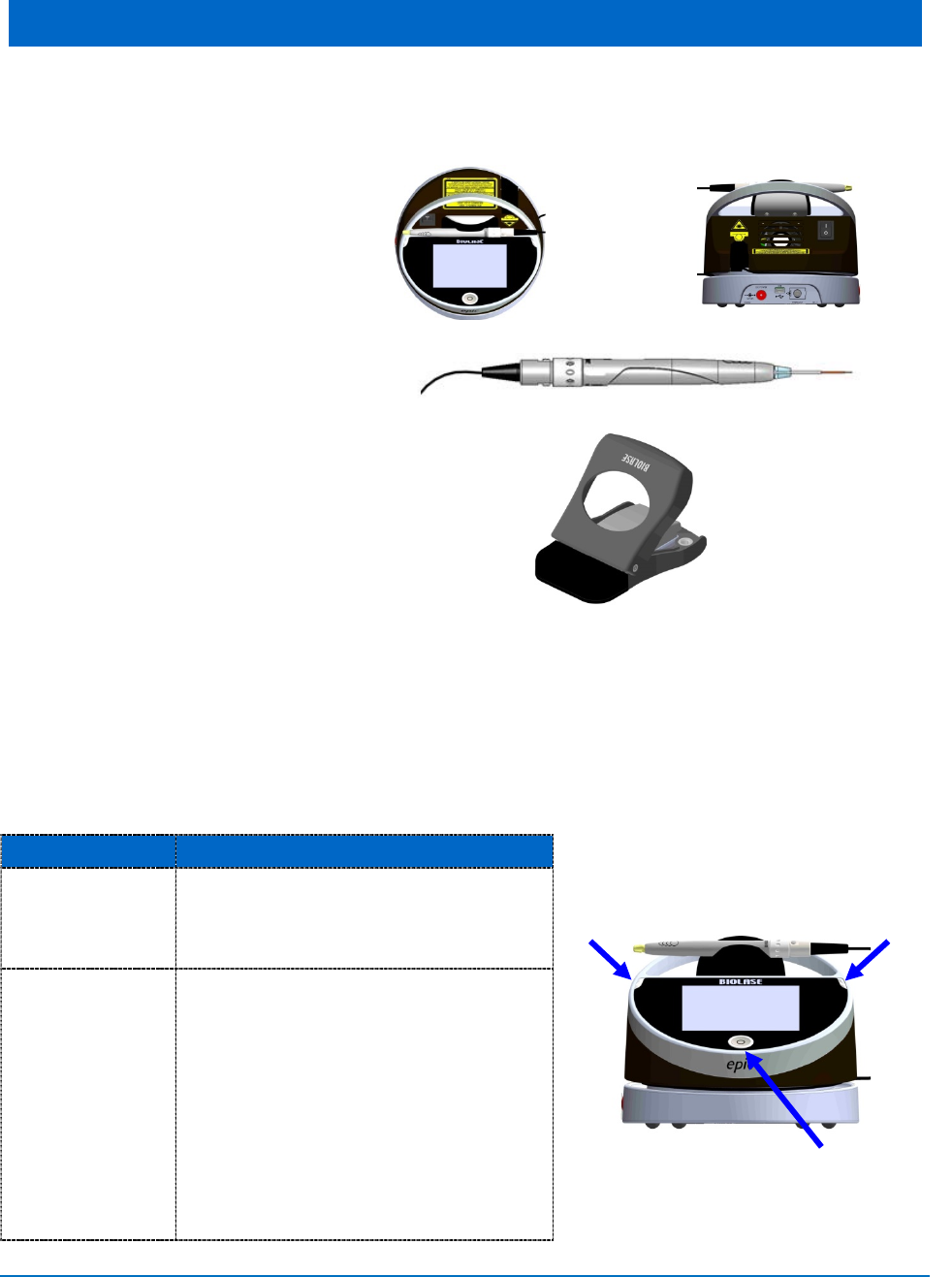
2.6 FIBER OPTIC CONNECTION
The EPIC 10 ships with the fiber optic cable already attached.
To disconnect the fiber optic cable from the laser console, make sure the laser console is
turned off and the cable is completely unwound from the console base, grab the fiber optic
access plug and slowly pull it straight back from the optical access port (Figure 2.3).
To re-install the fiber optic cable, make sure the laser console is turned off. The fiber optic
cable is attached to the console by inserting the optical access plug (Figure 2.2) into the optical
access port (Figure 2.3).
For storage, wind the cable in the fiber storage channel around the base of the console in a
counterclockwise direction (Figure 2.1).
CAUTION: Do not bend the fiber optic at a sharp angle, as it is can break. Make sure it is
not caught or pinched between the housing and the fiber optic access plug.
CAUTION:
Do not connect or disconnect the fiber while the laser console is turned on.
Only connect or disconnect the fiber when the laser console is turned off.
NOTE:
You should hear the fiber optic “click” into place; if you do not hear it “click,” remove
the fiber optic and reinstall it.
EPIC™10 User Manual
pg. 8
5400525 Rev B
Figure 2.2: Fiber Optic Access Plug
Figure 2.3: Optical Access Port
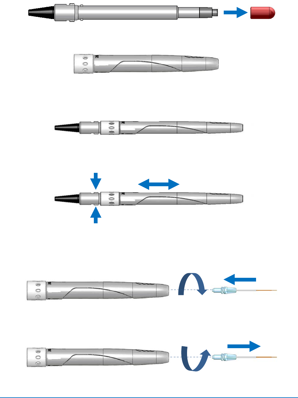
2.7 SINGLE-USE TIPS
The tips are single-use accessories and are provided in three core diameters: 200μm, 300μm,
and 400μm, in different lengths (see Appendix A).
CAUTION:
Tips are single-use only to avoid cross-contamination and are designed to
withstand only a single sterilization cycle; they must be disposed of after use in a
biohazard medical waste Sharps container.
Always visually inspect the tip prior to use to make sure it is free of debris or
damage.
To connect the tip, insert it firmly into the distal end of the handpiece as far as it will go, then
tighten by turning clockwise (Figure 2.7). Bend the metal cannula according to the specific
procedure requirements (Figure 2.10).
Remove the fiber tip by twisting the tip counterclockwise (Figure 2.8).
NOTE:
To provide proper laser operation, do not connect tips when the handpiece is
disconnected.
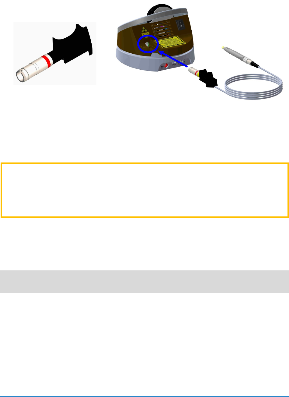
2.8 SURGICAL HANDPIECE ASSEMBLY
► To connect the handpiece to the fiber optic assembly, push the Handpiece on the fiber
shaft until it clicks on and is secured at connected position (Figures 2.4, 2.5).
► To disconnect the handpiece from fiber optic assembly (Figure 2.6):
• Take the handpiece body in one hand and the shaft in another
• Push the two buttons on the fiber shaft
• Pull the handpiece with the ring to separate.
EPIC™10 User Manual
pg. 9
5400525 Rev B
Fiber Shaft Protective Cap
Handpiece
Figure 2.4: Connecting the handpiece to the fiber optic assembly
Figure 2.5: Surgical handpiece assembly fully assembled
Figure 2.6: Disconnect the handpiece from the fiber optic assembly by pressing both buttons at the
base of the fiber shaft
Tip Assembly
Figure 2.7: Insert the fiber tip into the handpiece and twist clockwise until snug
Figure 2.8: Remove the fiber tip by twisting the tip counterclockwise
EPIC™10 User Manual
pg. 10
5400525 Rev B
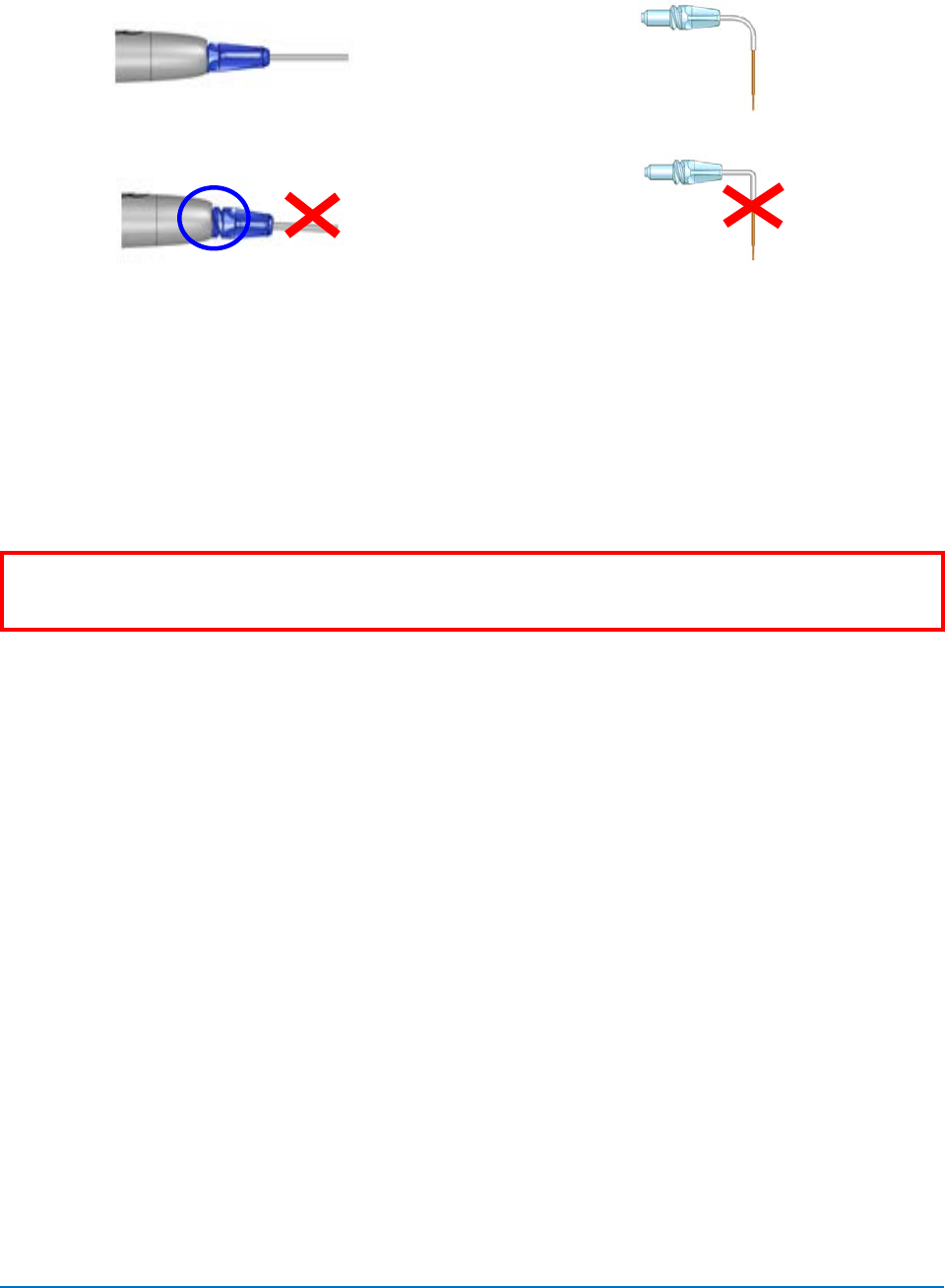
Correct Bend
Incorrect Bend
Figure 2.9: When installing the tip, make sure it is
seated properly (thread correctly) Figure 2.10: Bending the tip cannula
WARNING:
When the aiming beam is not present or has a significantly different shape,
change the tip.
EPIC™10 User Manual
pg. 11
5400525 Rev B
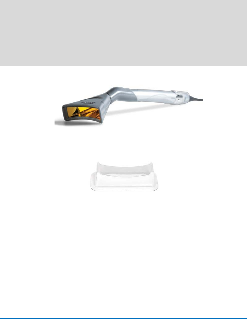
2.9 WHITENING/CONTOUR HANDPIECE (OPTIONAL ACCESSORY)
NOTE:
The Whitening/Contour Handpiece is reusable and equipped with a disposable non-
sterile protective shield for single patient use. The handpiece is non-sterile and
requires cleaning before and after each patient treatment. This handpiece cannot
be sterilized in the autoclave. For instructions on cleaning the handpiece, refer to
Section 8.
Always wipe the disposable shield with alcohol prior to use. The disposable shield is
for single-use only to avoid cross-contamination. Dispose of when treatment session
is completed.
Figure 2.13: Whitening/Contour Handpiece
Figure 2.14: Disposable Non-Sterile Shield
The area of Laser Energy Output for the Whitening/Contour Handpiece is 35mm x 8mm =
2.8cm2 Spot Size.
To connect the handpiece to the fiber optic cable, push the handpiece onto the fiber shaft until it
clicks on and is secured.
To disconnect the handpiece from the fiber optic assembly:
• Take the handpiece body in one hand and the shaft in another.
• Push two buttons on the fiber shaft.
• Pull the handpiece from the ring to separate.
EPIC™10 User Manual
pg. 12
5400525 Rev B
3. SAFETY
3.1 PRECAUTIONS
Failure to comply with precautions and warnings described in this User Manual may lead to
exposure to dangerous optical radiation sources. Please comply with all safety instructions and
warnings.
3.2 SAFETY INSTRUCTIONS
Follow these safety instructions before and during treatments:
• When the laser is in use, all operatory entrances must be marked with an appropriate
warning sign (one (1) included).
• Do not operate in the presence of explosive or flammable materials. Flammable
anesthetics or oxidizing gases such as nitrous oxide (N2O) and oxygen should be avoided.
Solvents of adhesives and flammable solutions used for cleaning and disinfecting should
be allowed to evaporate before laser is used. Attention should also be drawn to the danger
of ignition of endogenous gases.
• All persons present in the operatory must wear protective laser eyewear.
NOTE:
For replacement or additional protective laser eyewear, please contact BIOLASE.
CAUTION:
Periodically inspect laser eyewear for pitting and cracking.
LASER
WARNING:
Use of controls or adjustments or performance of procedures other than
those specified herein may result in hazardous radiation exposure.
WARNING:
Do not use this unit if you suspect it of functioning improperly or other than
described herein.
CAUTION:
This unit has been designed and tested to meet the requirements of
electromagnetic, electrostatic, and radio frequency interference standards.
However, the possibility of electromagnetic or other interference may still exist.
Relocating the device may help to eliminate the interference.
CAUTION: Always ensure that the proper laser parameters are set before the EPIC 10
laser is used in a clinical setting.
EPIC™10 User Manual
pg. 13
5400525 Rev B
LASER
WARNING:
Always ensure that the protective laser eyewear is appropriate for the
laser wavelength.
• Do not look directly into the beam or at specular reflections.
• Never direct or point the beam at a person’s eyes.
• Always place the system into STANDBY mode (by pressing the Control Button while in
READY mode) before exchanging Handpieces or disposable tips.
• Toggle the ON/OFF switch (located on the rear of the console) to the OFF (O) position
before leaving unit unattended.
LASER
WARNING:
Do not open unit housing at any time. Danger from optical radiation may
exist.
LASER
WARNING:
Do not aim the laser at metallic or reflective surfaces, such as surgical
instruments or dental mirrors. If aimed directly at these surfaces the laser
beam will reflect and create a potential hazard.
CAUTION:
Be aware that the metal / plastic cannula on the tips may become hot during
use. Avoid contact of the cannula with any tissue.
3.3 SAFETY FEATURES
Energy Monitor
The energy monitor measures and verifies power output. Power deviations of more than ± 20%
from the selected value will cause the display to show the error message: “LASER CURRENT
HIGH/LOW”.
The laser console will not operate until the system first clears the error and then goes into
READY mode. If the error message persists, please contact BIOLASE Service at
1-800-321-6717.
System Monitor
The system monitors the emergency stop switch, remote key, wireless footswitch connection,
and output power. An error in any one of these will stop the system. The text display will indicate
the type of error. Operation will not resume until the error is cleared.
EPIC™10 User Manual
pg. 14
5400525 Rev B
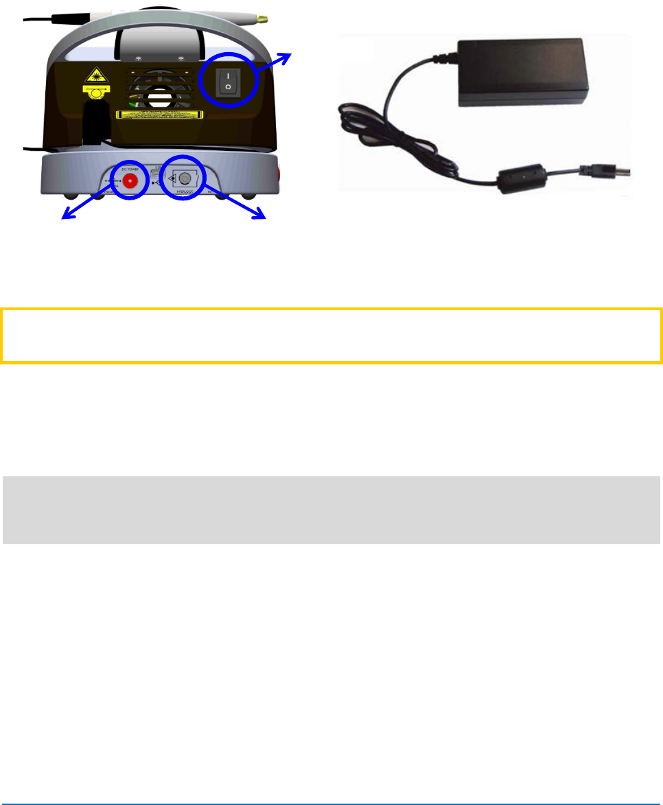
Power Switch
The laser console can be switched ON (I) or OFF (O) using the Power Switch on the back of the
console.
Figure 3.1: Power Switch, DC Power Input,
Remote Interlock
Figure 3.2: Power Supply Module with cord
CAUTION:
Use only the Power Supply Module (BIOLASE Part Number 2400129) supplied
with the EPIC 10 laser system.
Access Key Code
The Access Key Code prevents unauthorized use of the system. It is activated every time
system is turned on with the Power Switch (refer to Section 4 for code).
NOTE:
Placing the laser in SLEEP mode by pressing and holding the Control button on the
front panel does not re-set the Access Key Code. Turn the Power Switch OFF (O)
only when the system will not be in use for a long period of time.
Control Button
Once the power switch is set to the ON (I) position, enter the access key code. After setting the
desired parameters for a procedure, press the CONTROL button on the control panel to enter
into READY mode. The aiming beam will illuminate to indicate that the system is ready for use.
Wireless Footswitch
The EPIC will not emit laser energy until the user presses down on the Footswitch while the
laser is in READY mode. The footswitch is designed to work using wireless technology.
Power Switch
DC Power
Remote Interlock
EPIC™10 User Manual
pg. 15
5400525 Rev B
Two (2) AAA batteries are required to power the footswitch (included). (For instructions on how
to replace the footswitch batteries, see Section 4.)
Figure 3.3: Footswitch
Remote Interlock
This feature allows the laser console to be connected to the remote sensor, preventing its
operation when triggered (e.g., by opening door). The electric cable from this connector should
be wired to the normally closed switch, sensing the opening of a door and turning the laser
console off when the switch is open.
To override this feature, don’t connect the plug.
Figure 3.4: Remote Interlock Connector
Emergency Stop
Press the red Emergency Laser Stop button to instantly turn off the laser console. The error
screen will display an “Emergency Switch Error” message and the amber LED will begin
flashing. To clear the error, press the Emergency Laser Stop button again; in 2 to 5 seconds the
amber LED will stop flashing and the system will automatically go into STANDBY mode.

EPIC™10 User Manual
pg. 16
5400525 Rev B
Figure 3.5: Emergency Laser Stop (Left Profile View)
Functional Display
The System Color Display with Touch Screen and LED indicators on the control panel show the
functional conditions of the system.
3.4 SAFETY CLASSIFICATION
The following safety classifications are applicable to the device:
• Laser Radiation – Class 4
• Aiming Beam – Class 2
• Type of protections against electrical shock – Class 1
• Degree of protection against electrical shock – Type B Applied Part
• Not protected against water ingress – Ordinary Equipment
• Not suitable for use in presence of flammable anesthetic mixture
• Operation Mode – Continuous Wave and Pulse Mode
• Wireless Footswitch – IPX6
EPIC™10 User Manual
pg. 17
5400525 Rev B
4. OPERATION INSTRUCTIONS
4.1 SYSTEM SETUP
• Place the unit in a clean, dry, and well-ventilated area.
• Verify power switch is in the OFF (O) position.
• EPIC will work using either DC power or the rechargeable battery pack:
o DC Power: Connect the power cord of the power supply to the laser console and plug
into a wall outlet
o Rechargeable Battery: The EPIC is shipped with the battery pack already installed; to
charge the battery pack, connect the power cord of the DC power supply to the laser
console and plug into a wall outlet. Before first use, fully charge the battery (at least 3
hours). Once the battery is charged, unplug the power cord from the wall outlet and
the laser console. The laser console will run on battery power alone.
NOTE:
To fully charge the battery, plug the power supply in and then turn the laser console
ON (I) at the Power Switch. The laser console will start to charge and the unit will go
into sleep mode (with the screen off) after 5 minutes; if the power supply is plugged in
but turned OFF (O) at the Power Switch, the battery will still charge, but at a slower
rate.
• Connect the fiber to the laser console (see Section 2).
CAUTION:
Do not connect or disconnect the fiber while the laser console is turned ON.
Only connect or disconnect the fiber when the laser console is turned OFF.
CAUTION:
Do not cover or block ventilation channels. These channels provide an air-flow
path to cool the unit.
CAUTION:
Do not bend the fiber optic at a sharp angle, as it is can break. Make sure it is
not caught or pinched between the housing and the fiber optic access plug.
• Remove protective cap from the end of the fiber shaft (see Figure 2.4).
• Carefully connect the handpiece to the fiber optic assembly (see Figures 2.4, 2.5).
• Insert the selected tip and tighten it clockwise until snug (see Figure 2.7).
• Wind any excess fiber optic cable onto the fiber spool counterclockwise around the base
of the console.
• The handpiece is now ready to use. To store the handpiece, place it in the handpiece
holder located at the top of the laser console .
EPIC™10 User Manual
pg. 18
5400525 Rev B
LASER
WARNING:
Never point the laser at a person’s eyes.
LASER
WARNING:
Never operate the laser without a fiber tip attached.
LASER
WARNING:
All persons present in the operatory must wear protective eyewear when
the laser is in use.
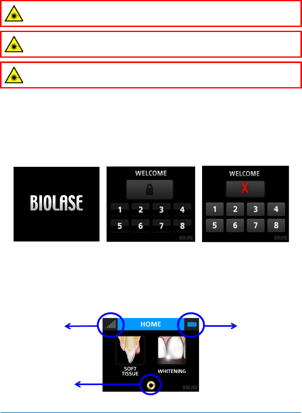
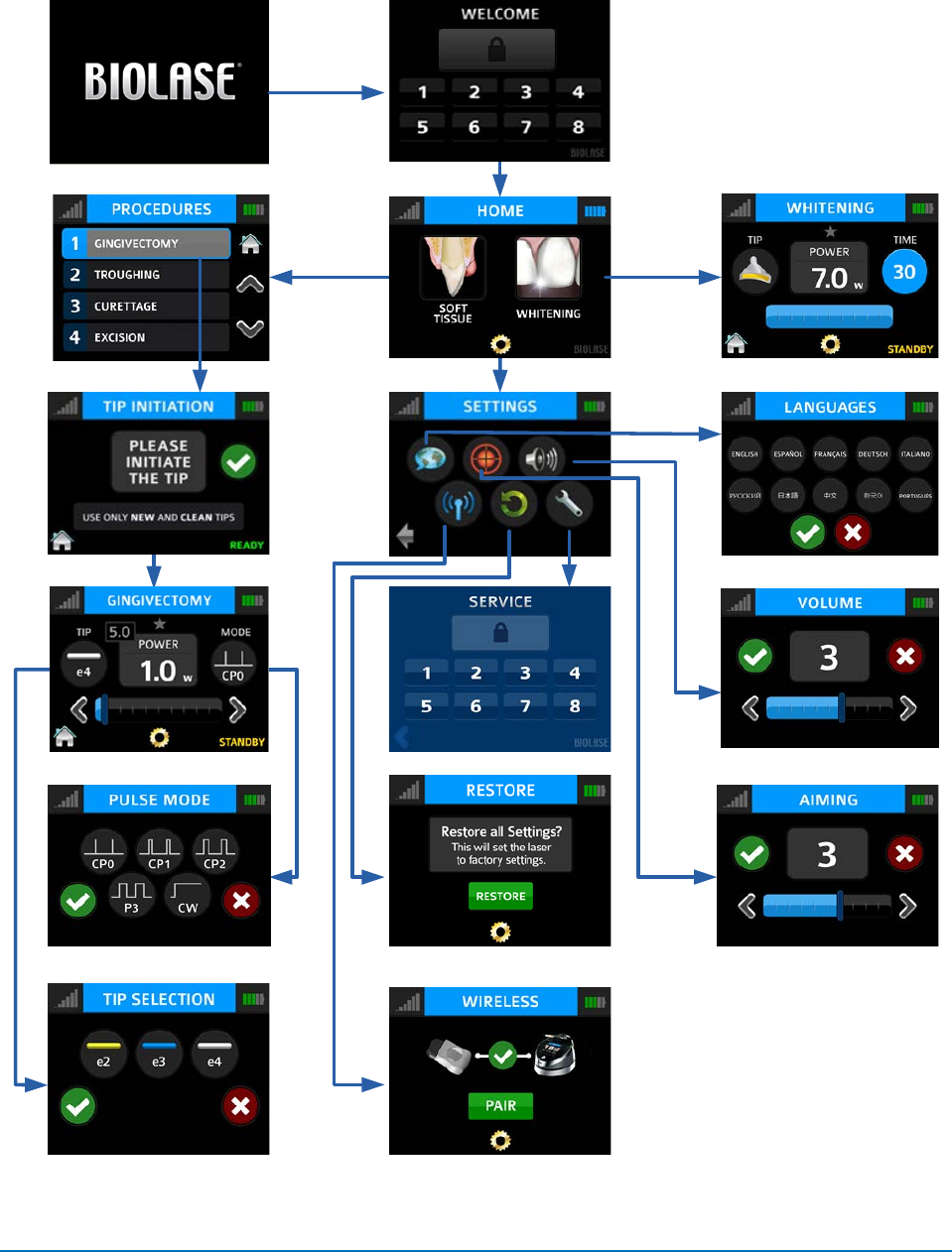
4.2 OPERATION - TURN ON THE EPIC 10 LASER
• Ensure that the battery has enough charge for operation, or connect the power supply
cord to the power connector on the laser console and plug the cord into a wall outlet.
• Turn the Power Switch at the rear of the console to the ON (I) position. The “BIOLASE”
logo screen will appear (Figure 4.1). After three (3) seconds the EPIC “Welcome” screen
will be displayed (Figure 4.2).
Figure 4.1
Figure 4.2
Figure 4.3
• Enter the three digit access code using the touch screen. The Access Key Code is 888.
(If the incorrect code is entered, an ‘X’ appears briefly in the window (Figure 4.3) and then
the screen reverts back to the Welcome screen; re-enter the correct code.)
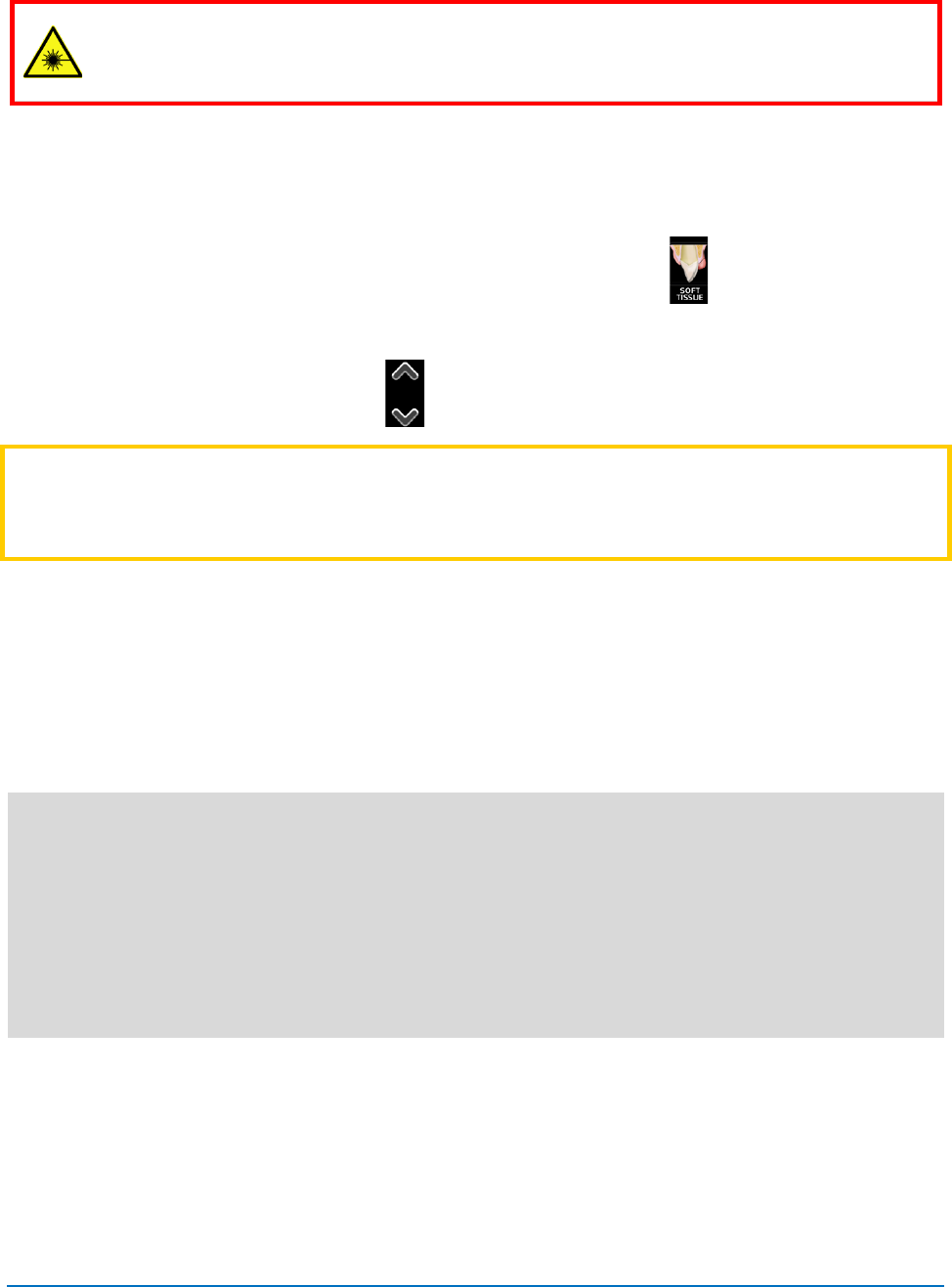
• The system will go to the HOME screen which identifies two procedure categories to
choose from: Soft Tissue, Whitening.
Figure 4.4: Home Screen
Wireless Signal
Strength Indicator
Laser Console Battery
Strength Indicator
Settings Button
EPIC™10 User Manual
pg. 19
5400525 Rev B
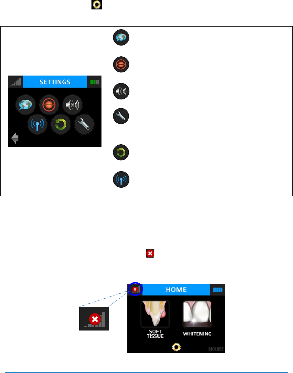
4.3 SETTINGS SCREEN
Pressing the Settings button on the HOME screen accesses the Settings screen; this
screen allows the user to make changes to several system settings:
Language Selection
Aiming Beam (5 levels of brightness adjustment)
Volume (5 levels of sound adjustment)
Service mode (accessible only by authorized BIOLASE Service
Representatives)
Restore to Factory Default Settings
Wireless Menu - Access to Pairing Screens
Figure 4.5
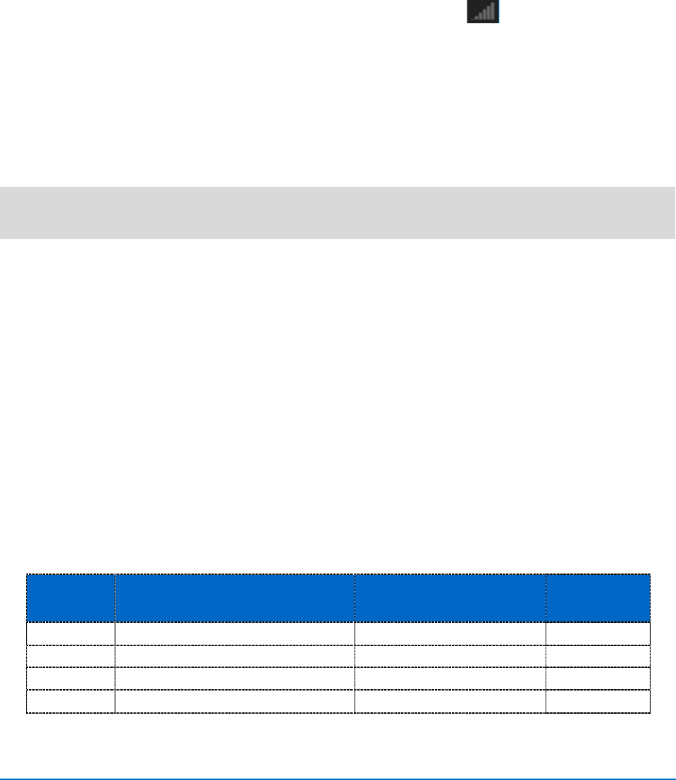
4.4 PAIRING THE FOOTSWITCH TO THE LASER CONSOLE
Verify that the footswitch and laser console are paired; a blue LED indicator light on the laser
console will blink when pairing is established. The laser and footswitch are shipped already
paired. However, if pairing is not confirmed, an “” will appear in the pairing icon located in the
upper left hand corner of the touchscreen (Figure 4.6).
Figure 4.6
EPIC™10 User Manual
pg. 20
5400525 Rev B
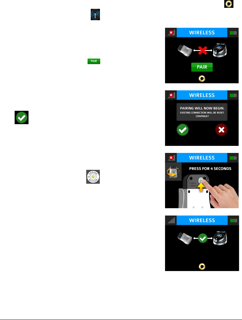
To re-establish pairing, take the following steps:
1. Go to the Settings menu on the laser console display by pressing the Settings button
and select the “Wireless” icon .
2. A screen will appear indicating that pairing of the
footswitch to the laser console has been lost (Figure 4.7);
press the green PAIR button.
Figure 4.7
3. The message that “PAIRING WILL NOW BEGIN” will
appear; press the green check mark to continue
(Figure 4.8).
Figure 4.8
4. To complete the pairing process, turn the footswitch over
and press the Pairing Button for four (4) seconds
(Figure 4.9).
Figure 4.9
5a. The Wireless screen will appear indicating that pairing
was successful and that the footswitch and laser console
are now paired (Figure 4.10). Proceed to step 6.
Figure 4.10
EPIC™10 User Manual
pg. 21
5400525 Rev B
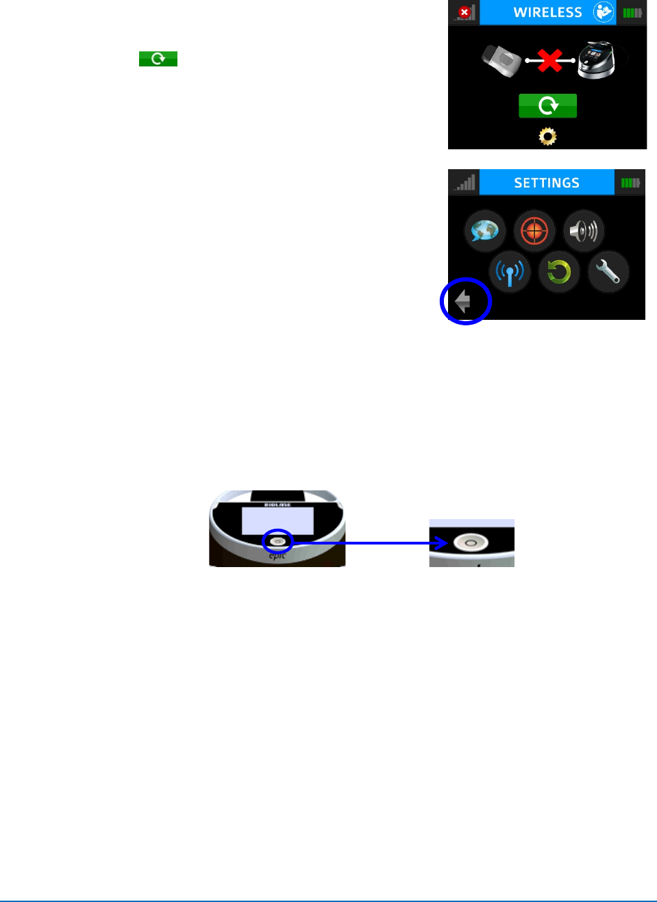
5b. If pairing has not occurred, the Wireless screen will
appear again indicating that pairing was not successful
(Figure 4.11); press the green button to repeat
steps 3 – 5a.
Figure 4.11
6. Press the Settings button to return to the Settings menu;
press the arrow on the bottom left of the Settings screen to
return to the Home screen (Figure 4.12).
Figure 4.12
4.5 CONTROL BUTTON
The CONTROL button on the front of the laser console is a multi-functional button (Figure 2.1).
Pressing and holding the Control Button for approximately two (2) seconds will allow the
transition from STANDBY or READY mode to SLEEP mode. Note that you will not be allowed
to go into READY mode unless you have chosen a treatment module on the HOME screen first.
4.6 ENTERING READY OR STANDBY MODES
Press and release the Control Button to place the laser console into either READY or
STANDBY mode. The laser console will only emit laser energy when the footswitch is pressed
and the laser console is set to READY mode. While in READY or STANDBY mode, mode
setting and/or power setting values may be changed only when the laser is not firing. If the
laser is firing (i.e., the footswitch is engaged), the ability to change the settings is blocked.
(“READY” or “STANDBY” is displayed in the lower right hand corner of the display screen).
4.7 READY MODE
When entering READY mode, the laser console fan will turn on and pressing the footswitch will
activate laser radiation. There is a two (2) sec delay between switching to READY mode and the
ability of the laser console to emit a laser beam.
EPIC™10 User Manual
pg. 22
5400525 Rev B
4.8 WIRELESS FOOTSWITCH
The wireless footswitch is powered by two (2) AAA batteries.
When the wireless footswitch is pressed in READY mode and the laser fires, a beeping sound
indicates that laser energy is present. A green LED will begin flashing and a blue LED will light
at the top corners of the laser console, confirming the footswitch and laser are paired.
In the top left corner of most screens is a Signal Strength Indicator which displays the
signal strength between the laser console and the footswitch (strongest is five (5) bars).
Pressing and releasing the footswitch while in STANDBY mode will update this indicator.
Although the unit will work with a signal level as low as one (1) bar, a weaker signal level will
make the connection between the footswitch and laser console more vulnerable to wireless (RF)
interference from other sources, such as cell phones or microwaves. To improve the signal
strength, reposition either the footswitch or the laser console until the signal indicator achieves
the strongest possible level for optimal operation.
NOTE:
When the footswitch will go into SLEEP mode when not in use to conserve battery
power. It automatically reactivates when it is pressed.
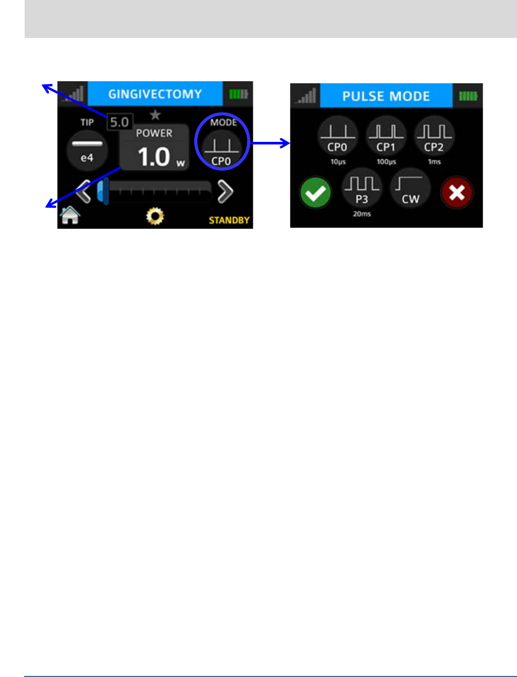
4.9 PEAK POWER DISPLAY
This number is shown only when the system is in Pulse mode and presents the value of the
peak power based on the Power Setting and Pulse mode.
4.10 PULSE MODE SELECTION
Pulse mode selection graphically indicates whether the system is in Continuous mode or in
Pulse mode.
In Continuous mode, laser power is constantly delivered when the laser console is in READY
mode and the wireless footswitch is activated.
In Pulse mode, laser power is delivered in repetitive pulses, controlled by the Pulse Length and
Pulse Interval settings. Pressing the Pulse Mode button will allow switching between Pulsed
and Continuous Modes (Figure 4.14).
MODE* PULSE DURATION (on) PULSE INTERVAL (off) Duty Cycle
(Time On / Time off)
CP0
10 microseconds
40 microseconds
20%
CP1
100 microseconds
200 microseconds
33%
CP2
1 millisecond
1 millisecond
50%
P3
20 milliseconds
20 milliseconds
50%
*CP = Comfort Pulse; P3 = Pulsed Mode which is the standard for most diode lasers currently available
to the marketplace
Figure 4.13
EPIC™10 User Manual
pg. 23
5400525 Rev B
NOTE:
Operating the laser at a shorter pulse duration typically results in lower tissue
temperature.
Figure 4.14
Average
Power
Peak
Power
EPIC™10 User Manual
pg. 24
5400525 Rev B
4.11 USING THE EPIC 10 TOUCH SCREEN DISPLAY
Figure 4.15
EPIC™10 User Manual
pg. 25
5400525 Rev B
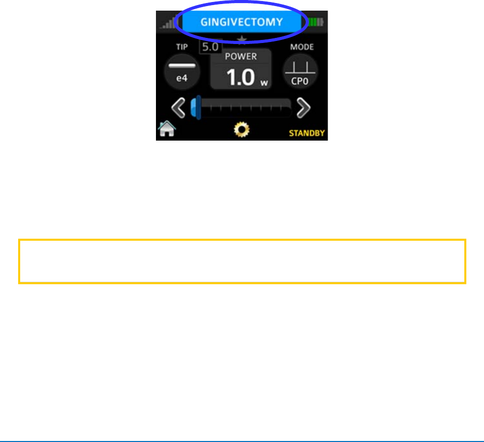
4.12 PROCEDURES BUTTON
The EPIC 10 has the ability to store up to 20 pre-set procedures; EPIC 10 is factory-installed
with 14 pre-programmed procedural presets and 6 empty slots for custom pre-sets. All of them
can be customized to your preference.
In order to customize the parameters for a particular clinical procedure:
1. Select PROCEDURES mode and scroll to the pre-set you wish to overwrite.
2. Adjust the operating parameters of the laser (e.g., power, pulse duration, interval, etc.).
3. Press and hold the name of the selected procedure (Figure 4.16) for approximately two (2)
seconds. Parameters for that procedure will be changed and saved (the laser console will
beep when the adjusted settings are saved).
Figure 4.16
4.13 TURN THE LASER CONSOLE OFF
• Wind the fiber cable onto the fiber spool counterclockwise around the base of the console.
• Place the handpiece onto the handpiece holder.
CAUTION:
Verify that the fiber optic tubing assembly is not twisted once the
handpiece is returned to the holder. The fiber may break if it is twisted.
• Press the CONTROL button on the front of the console for more than 2 seconds to turn
the display off.
• Press the Power Switch at the rear of the laser console to the OFF (O) position if the laser
system will not be used for a long period of time.

EPIC™10 User Manual
pg. 26
5400525 Rev B
5. SPECIFICATIONS
5.1 GENERAL
Dimension
5.7 in (W) x 4.4 in (H) x 6.5 in (L)
(14.5 cm x 11.2 cm x 16.5 cm)
Weight 2.5 lbs / 1kg
5.2 ELECTRICAL
Operating Voltage
100V - 240V ~ at 1.5A
Frequency
50/60Hz
External Fuses None
Main Control
Power Switch
Remote Interruption
Remote Interlock
Disable Control
Emergency Stop Button
Battery
Lithium Ion Rechargeable, 14.4V, 2.9Ah
DC Power Supply Module
12V DC, 5A
5.3 LASER
Laser Classification
IV (4)
Medium
InGaAsP Semi-conductor diode
Wavelength
940 ± 10nm
Max Power Output 10W
Power Accuracy
± 20%
Power Modes
Continuous, Pulse Modulation
Fiber Tips Diameter
200µm, 300 µm, 400µm

EPIC™10 User Manual
pg. 27
5400525 Rev B
Pulse Duration
0.01 ms – 20 ms
Pulse Interval
0.04 ms – 20 ms
Pulse Repetition Rate
Up to 20kHz (for reference)
Spot size
Surgical Handpiece 400 µm (maximum in contact mode)
Whitening Handpiece
Rectangular 35 mm x 8 mm = 2.8 cm2
NOHD
4.77 meters
Beam Divergence
8 - 22° per side angle
Standard Fiber Cable Length
5 feet (1.5 meters)
5.4 OTHER LIGHT SOURCES
Aiming Beam
Laser diode, max 1 mW, 625 nm – 670 nm

EPIC™10 User Manual
pg. 28
5400525 Rev B
6. CONTRAINDICATIONS, WARNINGS & PRECAUTIONS
6.1 CONTRAINDICATIONS
All clinical procedures performed with EPIC 10 must be subjected to the same clinical judgment
and care used with traditional techniques. Patient risk must always be considered and fully
understood before clinical treatment. The clinician must completely understand the patient’s
medical history prior to treatment. Exercise caution for general medical conditions that might
contraindicate a local procedure. Such conditions may include allergy to local or topical
anesthetics, heart disease (including pacemakers), lung disease, bleeding disorders, sleep
apnea or an immune system deficiency, or any medical conditions or medications that may
contraindicate use of certain light/laser type sources associated with this device. Medical
clearance from patient’s physician is advisable when doubt exists regarding treatment.
6.2 WARNINGS AND PRECAUTIONS
Prescription Statement
Federal Law restricts this device to sale by or on the order of a dentist or physician or other
licensed medical practitioner.
Eyewear
Doctor, patient, assistant and all others inside the operatory must wear appropriate laser
eyewear protection for the diode laser wavelength of 940 ± 10nm.
Anesthesia
In soft tissue cases anesthesia may not be required, but patients should be closely monitored
for signs of pain or discomfort at all times. If such signs are present, adjust settings, apply
anesthesia or cease treatment if required.
Adjacent Structures
EPIC 10 is designed to remove soft tissues. Therefore, always be aware of adjacent structures
and substructures during use. Be extremely careful not to inadvertently penetrate or ablate
underlying or adjacent tissues. Do not direct energy toward hard tissue such as tooth or bone.
Do not direct energy towards amalgam, gold or other metallic surfaces. Do not direct energy
towards cements or other filling materials. Exercise extreme caution when using this device in
areas such as pockets, cavities or channels such as third molar sockets, where critical
structures (i.e. nerves, vessels) could be damaged. Do not proceed with using the laser if
visibility is limited in these areas.

EPIC™10 User Manual
pg. 29
5400525 Rev B
Suction
Use high-speed suction as required to maintain a clear field of vision during treatment. Do not
use the EPIC if you cannot clearly see the treatment site.
Plume Removal
Special care must be taken to prevent infection from the laser plume generated by vaporization
of virally or bacterially infected tissue. Ensure that appropriate protective equipment (including
high-speed suction to remove the plume, appropriately filtered masks, and other protective
equipment) is used at all times during the laser procedure.
Clinical Use
Use your clinical judgment to determine all aspects of treatment including, but not limited to, the
laser treatment protocol, technique, power settings, pulse duration and interval settings, mode
of operation as well as the accessories (e.g. tip type) and other procedural requirements.
Closely observe and monitor clinical effects and use your judgment to determine clinical
parameters and approach for the treatment. Make appropriate power, pulse length, and interval
adjustments to compensate for varying tissue compositions, density, and thickness. Always start
treatment at the lowest power setting for that specific indication and increase as required.
BIOLASE assumes no responsibility for parameters, techniques, methods or results.
Training
Only licensed professionals who have reviewed and understood this User Manual should use
this device. BIOLASE assumes no responsibility for parameters, techniques, methods, or
results. Physicians must use their own clinical judgment and professionalism in determining all
aspects of treatment, technique, proper power settings, interval, duration, etc.

EPIC™10 User Manual
pg. 30
5400525 Rev B
7. CLINICAL APPLICATIONS
7.1 INTRODUCTION
To efficiently remove tissues it is imperative to understand the nature of the EPIC 10 device.
Please review this section carefully, practice on model tissues, and attend a diode laser training
session before using this device in a clinical situation.
7.2 INDICATIONS FOR USE
Use of the EPIC 10 laser device may be appropriate for incision, excision, vaporization, ablation
and coagulation of oral soft tissues including marginal and inter-dental gingival and epithelial
lining of free gingiva and the following specific indications:
• Excisional and incisional biopsies
• Exposure of unerupted teeth
• Fibroma removal
• Frenectomy
• Frenotomy
• Gingival troughing for crown impressions
• Gingivectomy
• Gingivoplasty
• Gingival incision and excision
• Hemostasis and coagulation
• Implant recovery
• Incision and drainage of abscess
• Leukoplakia
• Operculectomy
• Oral papillectomies
• Pulpotomy
• Pulpotomy as an adjunct to root canal
therapy
• Reduction of gingival hypertrophy
• Soft tissue crown lengthening
• Treatment of canker sores, herpetic and
aphthous ulcers of the oral mucosa
• Vestibuloplasty
• Tissue retraction for impression
• Laser soft tissue curettage
• Laser removal of diseased, infected,
inflamed and necrosed soft tissue within the
periodontal pocket
• Sulcular debridement (removal of diseased,
infected, inflamed and necrosed soft tissue in
the periodontal pocket to improve clinical
indices including gingival index, gingival
bleeding index, probe depth, attachment loss
and tooth mobility.)
• Light activation for bleaching materials for
teeth whitening
• Laser-assisted whitening/bleaching of teeth
EPIC™10 User Manual
pg. 31
5400525 Rev B
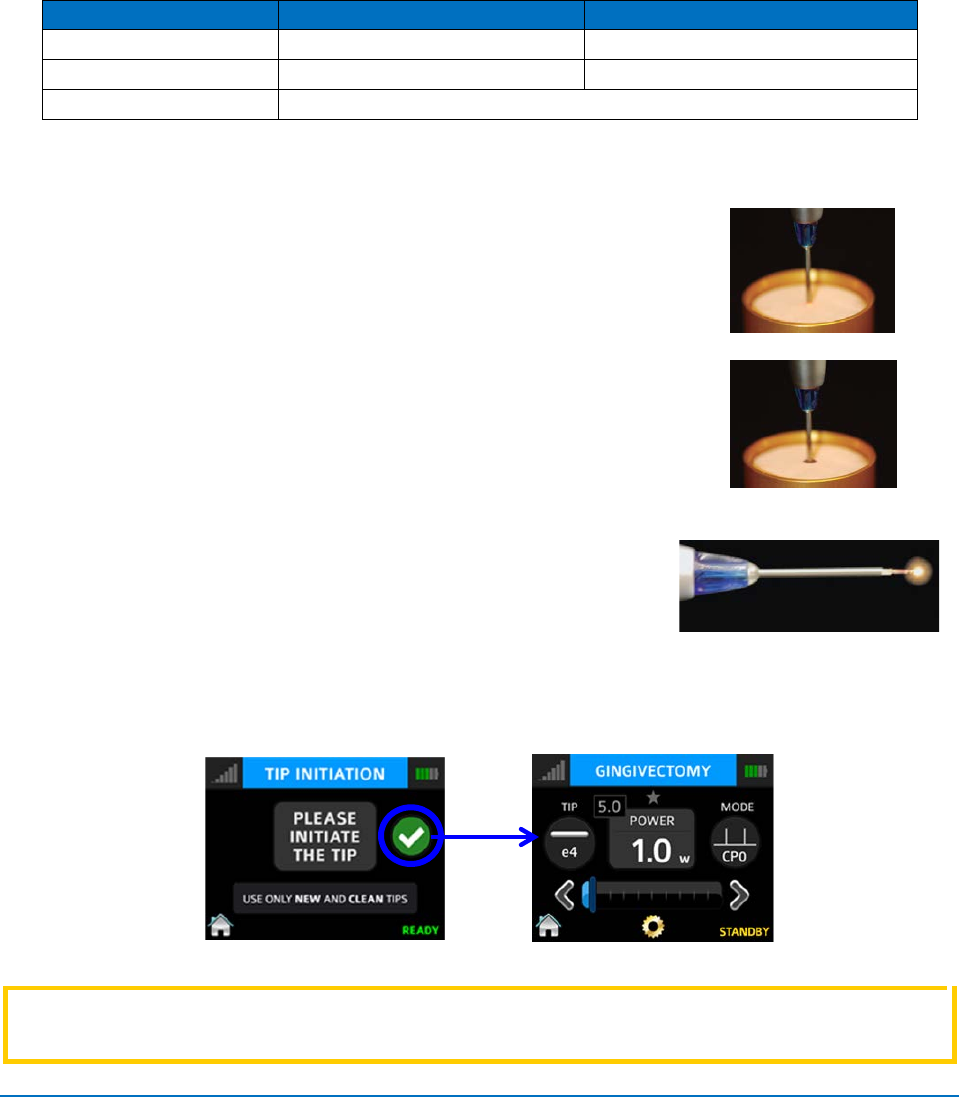
7.3 SOFT TISSUE SURGERY AND OTHER DENTAL USE
Tip Initiation: Parameters and Method
Most soft tissue surgical procedures require initiation of the fiber tip. The TIP INITIATION
screen will appear (in READY mode) if tip initiation is recommended; while in the TIP
INITIATION screen, initiate the tip by following the steps outlined below.
Tip Diameter (µm)
(Preset) Power (W)
Mode
400
1.4
CW
300
1.4
CW
200
Tip initiation not required when used for recommended procedures
Figure 7.1
● Review the table in Figure 7.1 to determine whether the tip requires initiation.
● Touch the tip to the surface of the initiation block, without
activating the laser (Figure 7.2).
Figure 7.2
● Press the footswitch to activate the laser, allowing the tip to
sink into the block. Pull the tip out when the metal cannula
touches the block, still firing until just before the tip is out of
the block (Figure 7.3).
Figure 7.3
● Press the footswitch to activate the laser into the air once, you
will see a white flash or the tip will glow (Figure 7.4).
Figure 7.4
● Repeat initiation process as needed to ensure the tip is initiated.
After tip initiation is completed, press the check mark to access the screen for the selected
procedure.
Figure 7.5
CAUTION:
If the laser console is in “READY” mode, the laser will fire if the footswitch is
activated.
EPIC™10 User Manual
pg. 32
5400525 Rev B
LASER
WARNING:
Never point the laser at a person’s eyes. All persons present in the
operatory must wear protective eyewear when the laser is in
operation
Pre-programmed Settings for Dental Procedures
To access the pre-programmed procedure values:
1. Go to the Procedures menu by pressing the Soft Tissue icon on the Home screen.
2. Press the button associated with the desired procedure.
3. Press the up and down arrows to scroll for additional procedures.
CAUTION:
Always use clinical judgment when selecting power, pulse, length, and pulse
interval parameters to ensure optimal clinical results. The recommended settings
apply only to the 300μm and 400μm tips.
To store your personal preferred settings for any procedure:
A. Follow steps 1 and 2 above.
B. Enter the new values.
C. Touch and hold the Procedure name for more than 2 seconds; you will hear a beeping
sound confirming the settings are saved.
NOTE:
The Procedure Pre-Sets installed at the factory are based on clinical
recommendations and feedback from experienced laser dentists.
300μm tips are recommended for removing thin tissue layers. 400μm tips are
recommended for removing fibrous tissue.
Always use your clinical judgment when selecting power, pulse length, and pulse
interval parameters to ensure optimal clinical results. At all times observe the clinical
effects on the treatment area and adjust parameters accordingly.

EPIC™10 User Manual
pg. 33
5400525 Rev B
7.4 TABLE OF PRE-PROGRAMMED SETTINGS
Preset Name Indications for Use Mode
Peak
Power
Avg.
Power
Pulse
Interval
Pulse
Length
Duty
Cycle
Tip
Type
Tip
Initiated?
1 Gingivectomy/Gingivoplasty
Reduction of gingival
hypertrophy,
Vestibuloplasty
CP0 5.0 W 1.0 W 0.04 ms 0.01 ms 20% E4 YES
2 Troughing
Tissue retraction for
impression, Gingival
troughing for crown
impressions
CP2 2.0 W 1.0 W 1.0 ms 1.0 ms 50% E4 YES
3 Curettage
Laser soft tissue
curettage
CP1 2.4 W 0.8 W 0.2 ms 0.1 ms 30% E4 YES
4 Excision
Fibroma removal,
Excisional and incisional
biopsies, Gingival incision
and excision,
Operculectomy, Oral
papillectomies, Incision
and drainage of abscess
CP1 2.7 W 0.9 W 0.2 ms 0.1 ms 30% E4 YES
5
Frenectomy/Frenotomy
Frenectomy/Frenotomy
CP2
2.0 W
1.0 W
1.0 ms
1.0 ms
50%
E4
YES
6
Implant Recovery
Implant Recovery
CP2
2.4 W
1.2 W
1.0 ms
1.0 ms
50%
E4
YES
7 Perio Pockets
Sulcular debridement
(removal of diseased,
infected, inflamed and
necrosed soft tissue in
the periodontal pocket to
improve clinical indices
including gingival index,
gingival bleeding index,
probe depth, attachment
loss and tooth mobility.)
CP2 1.6 W 0.8 W 1.0 ms 1.0 ms 50% E3 NO
8 Pulpotomy(*)
Pulpotomy, Pulpotomy as
an adjunct to root canal
CW 0.1 W 0.1 W N/A N/A N/A E4 YES
9 Crown Lengthening
Soft tissue crown
lengthening
CP1 2.7 W 0.9 W 0.2 ms 0.1 ms 30% E4 YES
10 Infected Pockets
Laser removal of
diseased, infected,
inflamed and necrosed
soft tissue within the
periodontal pocket
CP2 1.6 W 0.8 W 1.0 ms 1.0 ms 50% E4 YES
11 Endo (*) Pulpotomy, Pulpotomy as
an adjunct to root canal CW 0.1 W 0.1 W N/A N/A N/A E2 NO
12
Hemostasis
Hemostasis
CW
0.5 W
0.5W
N/A
N/A
N/A
E4
YES
13 Aphthous Ulcers
Treatment of canker
sores, herpetic and
aphthous ulcers of the
oral mucosa, Leukoplakia
CW 0.7 W 0.7 W N/A N/A N/A E4 NO
14 Exposure of Unerupted Teeth
Exposure of unerupted
teeth
CP2 0.7 W 0.7 W N/A N/A N/A E4 YES
15-17
Custom 1-3
N/A
CW
0.1 W
0.1 W
N/A
N/A
N/A
E4
YES
18-20
Custom 4-6
N/A
CW
0.1 W
0.1 W
N/A
N/A
N/A
E4
NO
(*)Minimum defaults provided for user setting of Endodontic Procedures such as Pulpotomy and
Pulpotomy as an adjunct to root canal therapy.
Figure 7.6
EPIC™10 User Manual
pg. 34
5400525 Rev B
7.5 TEETH WHITENING PROCEDURE
The following items are required to perform teeth whitening with the EPIC 10 laser:
• EPIC 10 laser
• Whitening/Contour Handpiece (Optional Accessory).
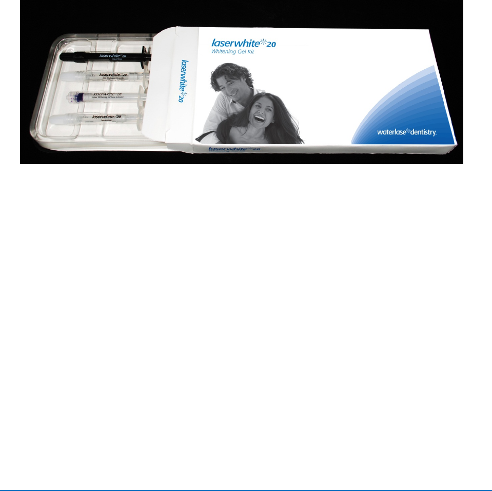
• LaserWhite™ 20 Whitening Gel Kit, BIOLASE p/n 7400063, sold separately in packs of
five (Figure 7.7).
Detailed step-by-step instructions, contraindications, precautions, and warnings for teeth
whitening are provided with the LaserWhite™ 20 Whitening Gel Kit. Please read the instructions
carefully before proceeding.
Figure 7.7: LaserWhite™ 20 Whitening Gel Kit (BIOLASE PN 7400063)

EPIC™10 User Manual
pg. 35
5400525 Rev B
8. MAINTENANCE
8.1 DAILY MAINTENANCE
Use the peel-off clear covers for the laser console supplied with the system. Use disinfectant to
wipe down the front panel and handpiece holder of the EPIC system after each procedure.
Do not use bleach or abrasive cleansers.
8.2 CLEANING AND STERILIZATION PROCEDURES
The contamination control suggested for the EPIC surgical handpiece and tips is the steam
sterilization method. However, before sterilization, the EPIC reusable handpiece should be
carefully cleaned per the following procedure.
CAUTION:
Tips are single-use only to avoid cross-contamination and are designed to
withstand a single sterilization cycle; they must be disposed of after use in a
biohazard medical waste Sharps container.
Handpieces are reusable and must be cleaned and sterilized between
patients to avoid cross-contamination.
Cleaning and Disinfecting Instructions for the Surgical Handpiece, and the
Reusable Fiber Optic Cable
The cleaning process is intended to remove blood, protein and other potential contaminants
from the surfaces and crevices of reusable accessories. This process may also reduce the
quantity of particles, microorganisms and pathogens present. Cleaning should be performed
prior to sterilization and must be conducted only by qualified office personnel trained to perform
the procedure and handle the EPIC fiber optic delivery system.
Wear protective latex gloves when handling the contaminated delivery system.
To disinfect the fiber cable, wipe the entire cable, including the shaft, with an appropriate
disinfecting solution, such as Cavicide™ or a similar quaternary ammonium compound
product (containing 20% alcohol or less), and follow the manufacturer’s instructions. Avoid
getting any liquid or debris near the distal end of the fiber cable.
WARNING:
Changes or modifications not expressly approved by Biolase could
void the user’s authority to operate the equipment.

EPIC™10 User Manual
pg. 36
5400525 Rev B
Manual Cleaning of the Surgical Handpiece:
Cleaning must be performed within a maximum of 1 hour after the procedure and always
prior to sterilization.
1. After use, carefully remove the tip from the handpiece and dispose of in a biohazard
medical waste Sharps container.
2. Carefully remove the handpiece from the fiber optic cable (see Section 2).
3. Prepare any commercially available surgical instrument detergent/enzymatic cleaning
solution with a pH of 7.0, such as Enzol® or similar enzymatic presoak and cleaner, per the
manufacturer’s instructions. (Follow the manufacturer’s instructions for disposal of used
solution.)
4.
Rinse the Handpiece under running lukewarm tap water (22 – 43°C)
for a
minimum of 10 seconds
to remove gross soil.
5. Wrap the handpiece in a piece of gauze that has been soaked in the cleaning solution;
leave it wrapped in the gauze for
a
minimum of 10 minutes.
6.
Unwrap the handpiece from the gauze and
use a soft-bristled brush dipped in the
cleaning
solution to gently
scrub it
for at least 15 seconds.
7. Rinse the handpiece under running lukewarm tap water (22-43°C) for a minimum of
10 seconds and then dry with a lint-free cloth.
8. Visually inspect the handpiece for any residual soil. If necessary, repeat steps 5 - 7 until
all residual soil is
removed.
Steam Sterilization for Surgical Handpiece, Single Use Tips
The steam sterilization process is intended to destroy infectious microorganisms and
pathogens.
• Place the handpiece and fiber tips in separate single-wrap, self-seal autoclave pouches.
• Place on an autoclave tray; do not stack other instruments on top of the pouches.
• Place the tray inside the autoclave chamber and set the appropriate cycle as
recommended in Figure 8.1.

EPIC™10 User Manual
pg. 37
5400525 Rev B
Type of Sterilizer Temperature Min Time Drying Time
Gravity Displacement
121°C ( 250°F) 30 minutes
15 – 30 minutes
132°C (270°F) 15 minutes
Dynamic-Air-Removal (Pre-Vacuum)
132°C (270°F)
4 minutes 20 - 30 minutes
134°C (273°F)
Figure 8.1
• Once the cycle is completed, remove the tray and let each sterilized item cool and dry.
The handpiece and tips must remain in the sterilization pouches until used in order
to maintain sterility.
Cleaning the Whitening/Contour Handpiece
The Whitening Handpiece is sold with disposable non-sterile protective shields.
The handpiece and clear protective shield are not autoclavable. The clear protective
shields are intended for one-time use only and should never be reused to avoid cross-
contamination.
To clean the Whitening Handpiece, wipe down the handpiece with gauze and isopropyl alcohol.
Always wipe the disposable shield with alcohol prior to use. Dispose of after single use.
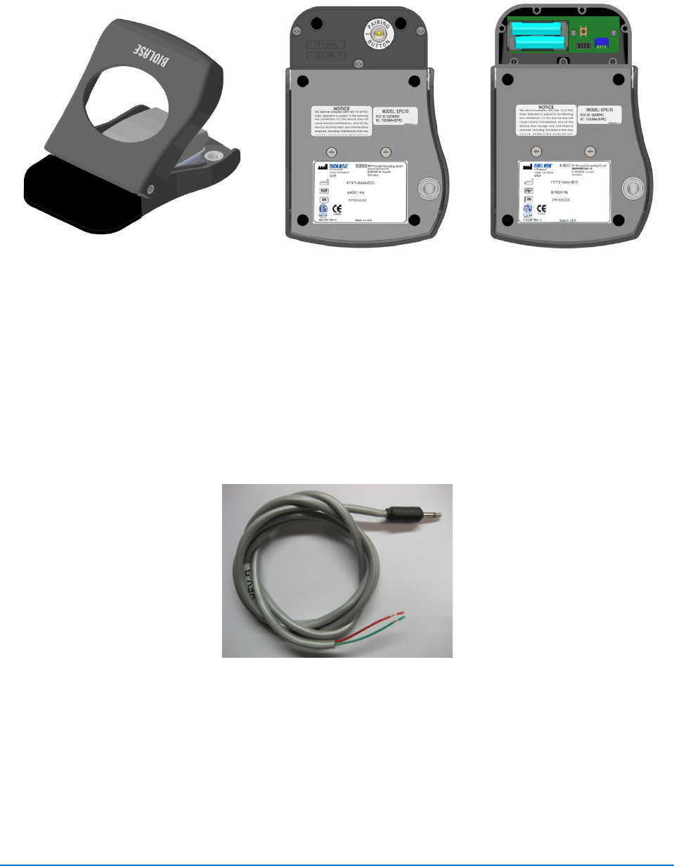
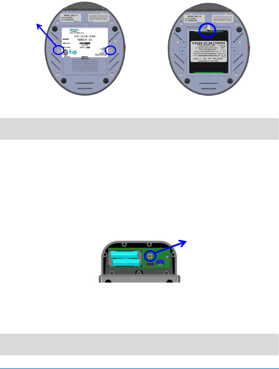
8.3 INSTALLING/REPLACING THE CONSOLE BATTERY PACK
1. To install or replace the battery pack, remove the battery cover on the underside of the
console using the Phillips screwdriver included with the laser system (Figure 8.1).
2. To remove the battery, grip the battery at the top and pull the cable away from the
connector (Figure 8.2). Do not tug or wrench the cable from the connector.
3. To install the battery, insert the connector wire from the battery to the unit, making sure
the red wire is on the left, and gently place the battery into the compartment (Figure 8.2).
4. Replace the battery cover on the bottom of the unit, using a standard Phillips
screwdriver.
5. Connect the power cord of the DC power supply to the unit and plug into a wall outlet.
Before first use, you should fully charge the battery (at least three (3) hours). Once the
battery is charged, unplug the power cord from the wall outlet and the console. The unit
will run on battery power alone. (See Section 4.1)
6. Recycle the used Lithium Ion battery as regulated. Do not throw it in a trashbin.
EPIC™10 User Manual
pg. 38
5400525 Rev B
Figure 8.1: Battery Cover/Bottom of Console
Figure 8.2: Battery Pack/Connector Wire
NOTE:
Only use the battery pack supplied by BIOLASE. The battery pack is a separate
accessory (BIOLASE p/n 6400457).
8.4 CHANGING THE WIRELESS FOOTSWITCH BATTERIES
The wireless footswitch is powered by two AAA batteries. When the batteries are low, a warning
message will appear on the touchscreen indicating that the batteries need to be replaced. To
replace the batteries, unscrew the battery cover on the underside of the footswitch (Section 3),
remove the old batteries, and install the new ones, replacing the cover when done. Dispose of
the used batteries as regulated; do not throw them in a trash bin.
Do not press/push/touch the Pairing Button (Figure 8.3) while changing the batteries, as this will
disrupt the pairing of the laser console and footswitch.
Figure 8.3
Although replacing the batteries will not disrupt the pairing of the laser console and footswitch, if
you find the wireless communication has been interrupted, reestablish pairing by following the
instructions provided in Section 4.
NOTE:
To ensure the longevity of the battery power, only BIOLASE-supplied batteries are
recommended as replacements (BIOLASE p/n 6400463); these are industrial-grade
Screws to remove
Battery cover
Pairing Button
(Internal View)

EPIC™10 User Manual
pg. 39
5400525 Rev B
batteries which under normal use have a longer life than conventional AAA batteries.
8.5 TRANSPORTATION
The EPIC 10 is susceptible to damage if not handled properly. The unit should ALWAYS be
handled carefully and never banged, jarred, jolted, dropped, or knocked.
Do not transport the unit unless it is completely packaged inside its shipping box. If you have
any questions regarding transportation please call BIOLASE Service at 1-800-321-6717.
8.6 STORAGE
The EPIC 10 should be stored in a cool, dry place when not in use. Storage temperature
15°C-35°C (59°F-95°F), relative humidity 10%-70%, non-condensing. Cover the unit when not
in use for extended periods of time. Store the system in a place where it will not be accidentally
bumped or banged.
CAUTION:
Make sure the distal end of the handpiece shaft is protected from dirt with
the protective tip plug and handpiece.
CAUTION:
Remove the batteries from the footswitch if the EPIC 10 is not likely to be
used for some time.
The EPIC 10 laser system is shipped inside a custom shipping box. Please save and store the
box in a cool, dry place for use when transporting the laser, or for long-term storage.

EPIC™10 User Manual
pg. 40
5400525 Rev B
9. CALIBRATION
9.1 CALIBRATION SCHEDULE
Calibration procedure is recommended to be performed every twenty-four (24) months in order
to maintain the required accuracy of output power versus displayed power. Annual calibrations
can be performed at a certified depot repair facility. Call BIOLASE Service at 1-800-321-6717 or
your Authorized Service Representative to schedule an appointment.
10. SOFTWARE SPECIFICATION
BIOLASE respects the intellectual property of others, and we ask our users to do the same.
EPIC 10 software is protected by copyright and other intellectual property laws.
This product contains proprietary, copyrighted software developed by BIOLASE, Inc. All rights
reserved in the USA and other countries.
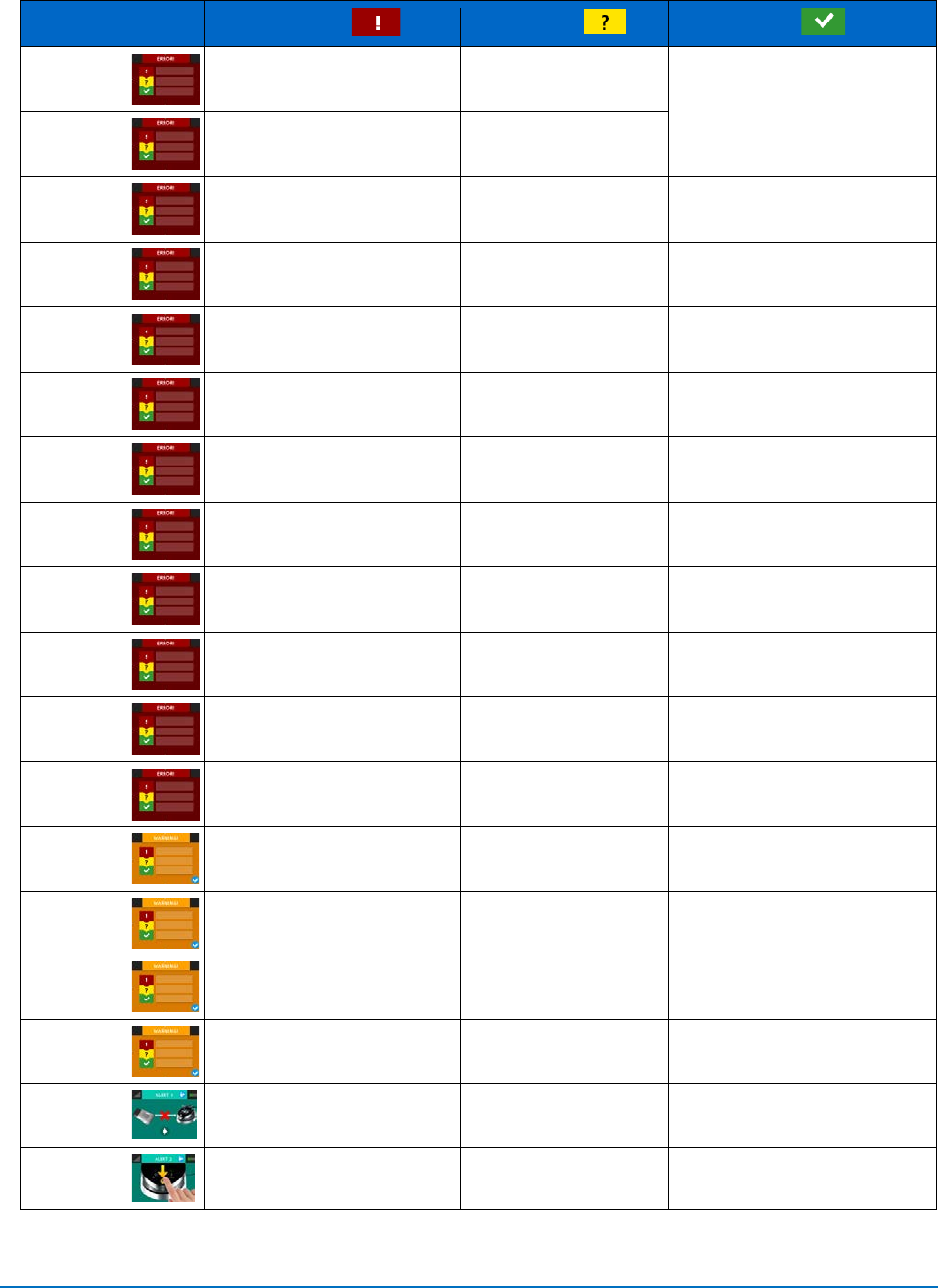
11. TROUBLESHOOTING
Should any of the on-screen messages listed in Figure 11.1 appear, follow the troubleshooting
instructions for the specific message as noted below.
NOTE:
For any on-screen message not listed in Figure 11.1, re-power the laser console; if
the message does not clear, call BIOLASE Service at 1-800-321-6717 or your
authorized Service Representative
EPIC™10 User Manual
pg. 41
5400525 Rev B
Title
Message
Reason
Fix
Error 1
Thermistor Open
Thermistor Open
Call BIOLASE Service
Error 2
Thermistor Shorted
Thermistor Shorted
Error 3
Shutdown Temperature
System too hot
Allow 5-10 mins for laser to cool
down
Error 4
Laser Current High/ Low
Output is out of specs
Call BIOLASE Service
Error 5
FS shorted in Standby
FS is partially pressed or
is damaged
Press/Release FS or call Biolase
Service
Error 6
ON/OFF button Stuck
Key stuck
Press Front key
Error 7
Flash Corrupted
Memory Corrupted
Call BIOLASE Service
Error 8
No Fiber
Fiber not inserted
Plug in Trunk Fiber
Error 9
Lost Footswitch Communication
Wireless Interference
Reposition console or FS to
improve communication
Error 10
Emergency Switch
E-Switch Pressed
Press E-Switch Again
Error 11
Remote Interlock
Remote interlock open
Check Remote Interlock closed
Error 12
Battery Critically Low
Battery Critically Low
Plug in DC supply
Warning 1
Temp High
System is hot
Allow 5-10 mins for laser to cool
down
Warning 2
Battery Low
Battery is low
Plug in DC supply
Warning 3
Battery Not Connected
Battery not connected
Plug in Battery
Warning 4
FS Battery Low
Battery on FS low
Replace FS battery
Alert 1
Wireless Not Paired
No wireless connect
Re-establish pairing (see Sec 4)
Alert 2
System must be in READY
mode to lase
System is not in READY
mode
Press the Control Button in any
procedure screen
Figure 11.1
EPIC™10 User Manual
pg. 42
5400525 Rev B
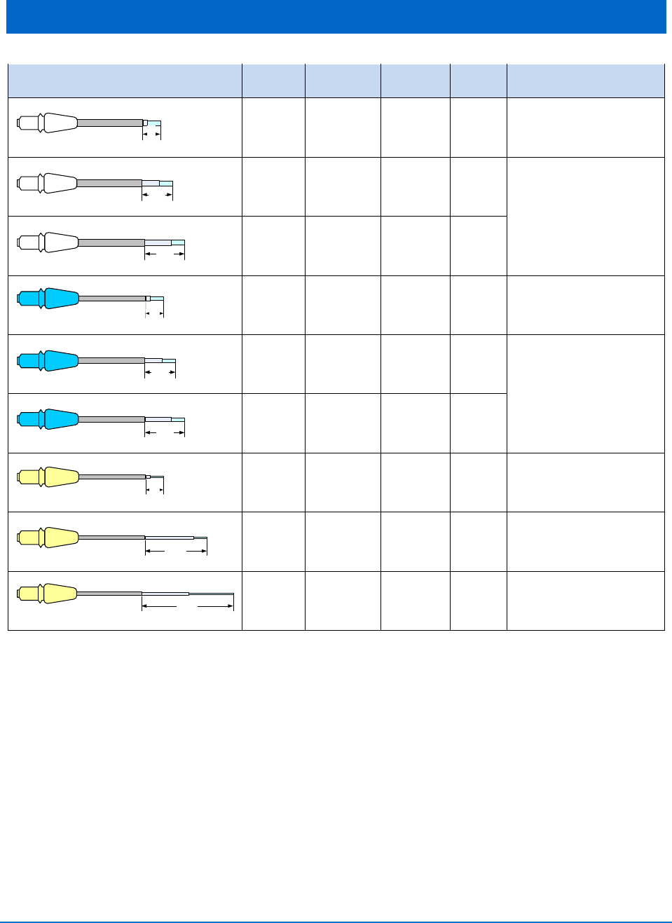
APPENDIX A – TIP GUIDE
Tip Name
Diameter
(µm)
Length
(mm)
Qty Part Number
4
mm
E4-4 400µm 4 30 7400016
7mm
E4-7 400µm 7 15 7400019
Combo Pack
15 x E4-7, 15 x E4-9
9mm
E4-9 400µm 9 15
4
mm
E3-4 300µm 4 30 7400017
7mm
E3-7 300µm 7 15 7400020
Combo Pack
15 x E3-7, 15 x E3-9
9mm
E3-9 300µm 9 15
4
mm
E2-4 200µm 4 30 7400018
14mm
E2-14 200µm 14 30 7400021
20mm
E2-20 200µm 20 20 7400015
EPIC™10 User Manual
pg. 43
5400525 Rev B
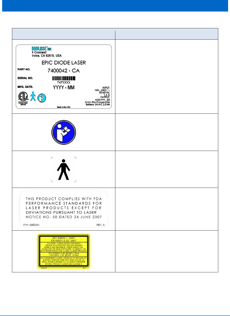
APPENDIX B – LABELING
Symbols
Description
Product ID Label
Location: Bottom of laser console
Refer to User Manual
Type B Applied Part:
The applied part is not conductive to the
patient.
FDA Compliance Label:
Indicates the device complies with FDA laser
standards.
Warning Label:
Indicates there is the risk of possible
exposure to both infrared and visible laser
radiation.
Location: Back of laser console
EPIC™10 User Manual
pg. 44
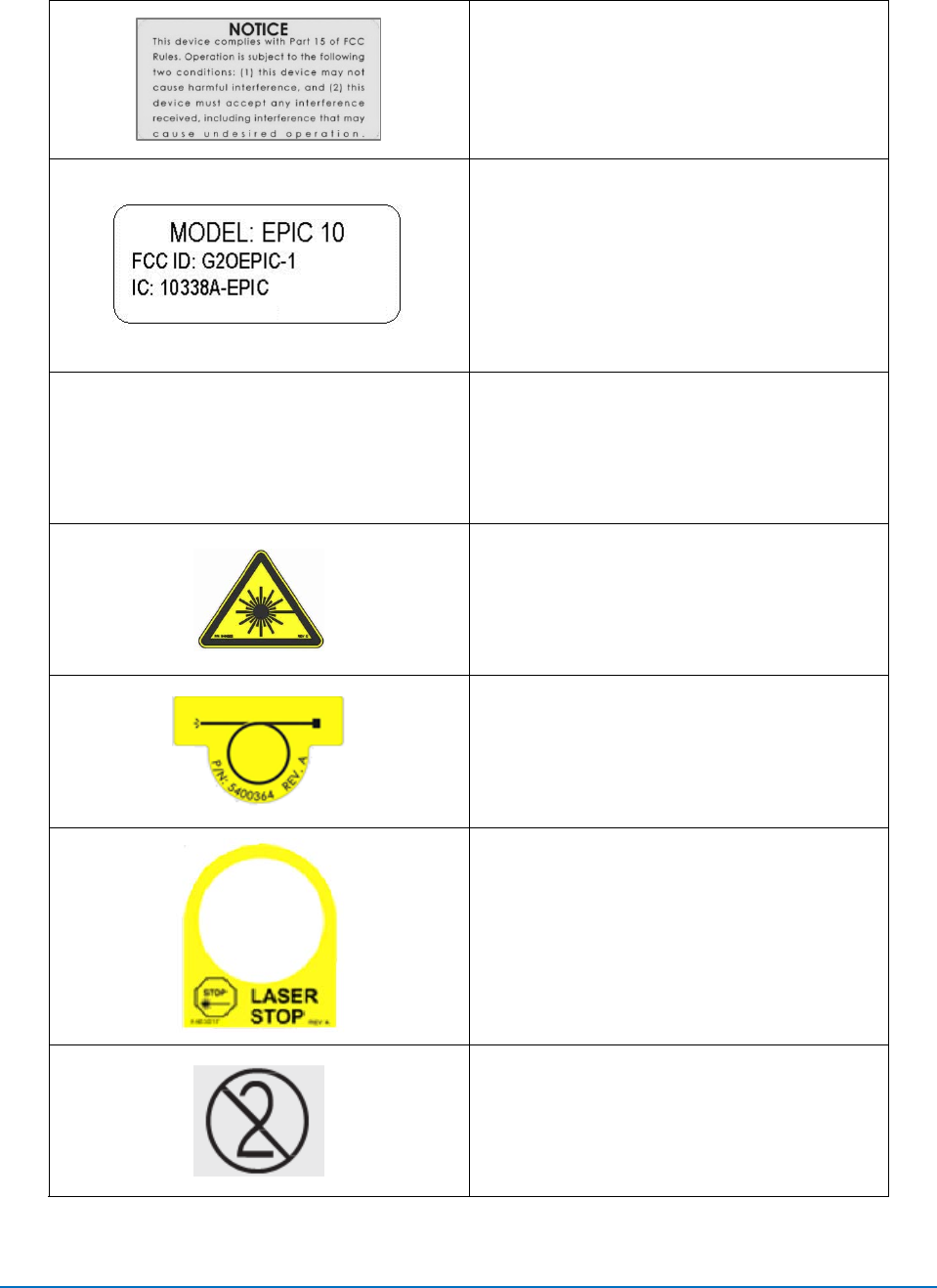
5400525 Rev B
FCC Compliance Notice:
The footswitch and laser console comply with
Part 15 of FCC Rules regarding unlicensed
transmissions.
Location: Bottom of Footswitch
FCC and IC Label:
Lists Federal Communication Commission
and Industry Canada registration numbers.
IPX6
Ingress Protection Code:
The footswitch is water-resistant, protected
against splashes of water.
Laser Warning:
Indicates the system contains a laser.
Location: Back of Laser Console
Fiber Warning:
Indicates the laser aperture is at the end of
the fiber.
Location: Back of Laser Console
Emergency Laser Stop Switch:
The switch used in emergencies to stop laser
output.
Location: Right side of Laser Console
DO NOT REUSE
For single use only.
EPIC™10 User Manual
pg. 45
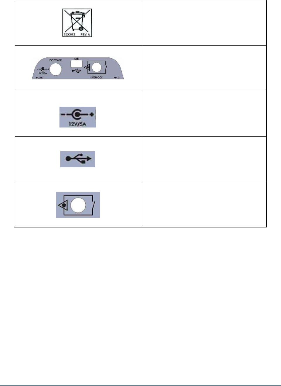
5400525 Rev B
WEEE (Waste Electrical and Electronic)
Recycle Lithium Ion battery as regulated. Do
not throw in trash bin.
DC Power, USB, Remote Interlock Label:
Identifies input ports
Power Input Rating:
12 Volts Direct Current, 5 amps
Mini USB Input:
For external programming
Remote Interlock:
Input for Remote Interlock Connector which,
when applied to the access door of the
operatory and activated, will shut off the
laser.

EPIC™10 User Manual
pg. 46
5400525 Rev B
APPENDIX C – SAFETY PRECAUTIONS FOR LITHIUM-
ION BATTERY PACKS
WHEN USING THE BATTERY
WARNING
1. Misusing the battery may cause the battery to get hot, rupture, or ignite and cause
serious injury. Be sure to follow the safety rules listed below:
• Do not place the battery in fire or heat the battery.
• Do not install the battery backwards so that the polarity is reversed.
• Do not connect the positive terminal and the negative terminal of the battery to each
other with any metal object (such as a wire).
• Do not carry or store the batteries together with necklaces, hairpins, or other metal
objects.
• Do not pierce the battery with nails, strike the battery with a hammer, step on the
battery, or otherwise subject it to strong impacts or shocks.
• Do not solder directly onto the battery.
• Do not expose the battery to water or salt water, or allow the battery to get wet.
2. Do not disassemble or modify the battery. The battery contains safety and protection
devices which, if damaged, may cause the battery to generate heat, rupture, or ignite.
3. Do not place the battery on or near fires, stoves, or other high-temperature locations. Do
not place the battery in direct sunshine or use or store the battery inside cards in hot
weather. Doing so may cause the battery to generate heat, rupture, or ignite. Using the
battery in this manner may also result in a loss of performance and a shortened life
expectancy.
CAUTION
1. If the device is to be used by small children, the caregiver should explain the contents of
the user’s manual to the children. The caregiver should provide adequate supervision to
ensure that the device is being used as explained in the user’s manual.
2. When the battery is worn out, insulate the terminals with adhesive tape or similar
materials before disposal.

EPIC™10 User Manual
pg. 47
5400525 Rev B
3. Immediately discontinue use of the battery if, while using, charging, or storing the
battery, the battery emits an unusual smell, feels hot, changes color, changes shape, or
appears abnormal in any other way. Contact your sales location or BIOLASE if any of
these problems are observed.
4. Do not place the batteries in microwave ovens, high-pressure containers, or on induction
cookware.
5. In the event that the battery leaks and the fluid gets into one’s eye(s), do not rub the
eye(s). Rinse well with water and immediately seek medical care. If left untreated, the
battery fluid could cause damage to the eye.
WHEN CHARGING THE BATTERY
WARNING
1. Be sure to follow the rules listed below while charging the battery. Failure to do so may
cause the battery to become hot, rupture, or ignite and cause serious injury.
• When charging the battery, either use a specified battery charger or otherwise
ensure that the battery charging conditions specified are met.
• Do not attach the batteries to a power supply plug or directly to a car’s cigarette
lighter.
• Do not place the batteries in or near fire, or into direct sunlight. When the battery
becomes hot, the built-in safety equipment is activated, preventing the battery from
charging further, and heating the battery can destroy the safety equipment and can
cause additional heating, breaking, or ignition of the battery.
2. Do not continue charging the battery if it does not recharge within the specified charging
time. Doing so may cause the battery to become hot, rupture, or ignite.
CAUTION
The temperature range over which the battery can be charged is 0°C to 45°C. Changing the
battery at temperatures outside of this range may cause the battery to become hot or to break.
Charging the battery outside of this temperature range may also harm the performance of the
battery or reduce the battery’s life expectancy.

EPIC™10 User Manual
pg. 48
5400525 Rev B
WHEN DISCHARGING THE BATTERY
WARNING
Do not discharge the battery using any device except for the specified device. When the battery
is used in devices aside from the specified device it may damage the performance of the battery
or reduce its life expectancy, and if the device causes an abnormal current to flow, it may cause
the battery to become hot, rupture, or ignite and cause serious injury.
CAUTION
The temperature range over which the battery can be discharged is -20°C to 60°C. Use of the
battery outside of this temperature range may damage the performance of the battery or may
reduce its life expectancy.

EPIC™10 User Manual
pg. 49
5400525 Rev B
APPENDIX D - SPARE PARTS & ACCESSORIES
SYSTEM ACCESSORIES
BIOLASE p/n
Description
6400479
Surgical Handpiece (2-pack)
2400040
Laser Safety Glasses (Clinician)
6400058
Remote Interlock Plug
2400129
Power Cord with Power Supply
6400146
Wireless Footswitch
6400107
Tip initiation kit
7400022
Whitening/Contour Handpiece
6400180
Whitening Handpiece disposable shields (30-pack)
7400063
LaserWhite 20 Whitening Gel Kit (pack of 5)
6400465
Peel-off clear screen covers (qty. 30)
6400457
Lithium ion battery pack for console
6400463
Battery Pack, (2 x AAA)
6400437
Trunk Fiber Assembly
SINGLE USE TIPS
Surgical:
BIOLASE p/n
Description
7400018
200 µm core diameters (qty. 30)
7400017
300 µm core diameters (qty. 30)
7400016
400 µm core diameters (qty. 30)

EPIC™10 User Manual
pg. 50
5400525 Rev B
Perio:
BIOLASE p/n Description
7400020 300 µm core diameters (qty. 30)
7400019 400 µm core diameters (qty. 30)
Endo:
BIOLASE p/n
Description
7400015 EZTIP Endo Kit, E2, 20mm
7400021 200 µm core diameters (qty. 30)

EPIC™10 User Manual
pg. 51
5400525 Rev B
APPENDIX E – ELECTROMAGNETIC COMPATIBILITY
GUIDANCE AND MANUFACTURER’S DECLARATION – ELECTROMAGNETIC IMMUNITY
The model Epic 10 is intended for use in the electromagnetic environment specified below. The customer
or the user of the model Epic 10 should assure that it is used in such an environment.
Immunity test
IEC 60601
test level
Continuous
level
Electromagnetic environment -
guidance
Electrostatic
discharge (ESD)
IEC 61000-4-2
± 6 kV contact
± 8kV air
± 6 kV contact
± 8kV air
Floors should be wood, concrete or
ceramic tile. If floors are covered with
synthetic material, relative humidity
should be at least 50%.
Electrical fast
transient/burst
IEC61000-4-4
± 2 kV for power
supply lines
± 1 kV for
input/output lines
± 2 kV for power
supply lines
N/A
Main power quality should be that of a
typical commercial or hospital
environment.
Input/output that does not apply
because the footswitch cable length is
less than 3 meters.
Surge
IEC 61000-4-5
± 1 kV differential
mode
± 2kV common
mode
± 1 kV differential
mode
± 2kV common
mode
Mains power quality should be that of
a typical commercial or hospital
environment.
Voltage dips, short
interruptions and
voltage variations
on power supply
input lines.
IEC 61000-4-11
<5% Ur
(>95% dip in UT)
for 0.5 cycle
40% Ur
(60% dip in UT) for
5 cycles
70% Ur
(30% dip in Ur) for
25 cycles
<5% Ur
(>95% dip in Ur) for
5 seconds
<5% Ur
(>95% dip in UT)
for 0.5 cycle
40% Ur
(60% dip in UT) for
5 cycles
70% Ur
(30% dip in Ur) for
25 cycles
<5% Ur
(>95% dip in Ur) for
5 seconds
Mains power quality should be that of
a typical commercial or hospital
environment. If the user of the model
Epic 10 requires continued operation
during power mains interruptions, it is
recommended that the model Epic 10
be powered from an uninterrupted
power supply.
Power frequency
(50-60 Hz)
magnetic field
IEC 61000-4-8
3 A/m
3 A/m
Power frequency magnetic fields
should be at levels characteristic of a
typical location in a typical commercial
or hospital environment.
NOTE: Ur is the A.C. mains voltage prior to applications of the test level.
EPIC™10 User Manual
pg. 52
5400525 Rev B
GUIDANCE AND MANUFACTURER’S DECLARATION – ELECTROMAGNETIC IMMUNITY (Continued)
The model Epic 10 is intended for use in the electromagnetic environment specified below. The customer
or the user of the model Epic 10 should assure that it is used in such an environment.
Immunity test
IEC 60601
test level
Continuous
level
Electromagnetic environment -
guidance
Conducted RF
IEC 61000-4-6
Radiated RF
IEC61000-4-3
3 Vrms
150 kHz to 80 GHz
3V/m
80 MHz to 2.5 GHz
3 V
3Vm
Portable and mobile RF
communications equipment should be
used no closer to any part of the
model Epic 10, including cables, than
the recommended separation distance
calculated from the equation
applicable to the frequency of the
transmitter.
Recommended separation distance
d = 1.2√P
d = 1.2√P 80 MHz to 800 MHz
d = 2.3√P 800MHz to 2.5GHZ
Wher P is the maximum output power
rating of the transmitter in watts (W)
according to the transmitter
manufacturer and d 8s the
recommended separation distance in
meters (m).
Field strengths from fixed RF
transmitters, as determined by an
electromagnetic site survey,a should
be less than the compliance level in
each frequency range.b
Interference may occur in the vicinity
of equipment marked with the
following symbol:
NOTE 1 - At 80 MHz and 800 MHz, the higher frequency range applies.
NOTE 2 – These guidelines may not apply in all situations. Electromagnetic propagation is affected by
absorption and reflection from structures, objects, and people.
A. Field strengths from fixed transmitters, such as base stations for radio (cellular/cordless) telephone and land mobile radios,
amateur radio, AM and FM radio broadcast and TV broadcast cannot be predicted theoretically with accuracy. To assess the
electromagnetic environment due to fixed RF transmitters, an electromagnetic site survey should be considered. If the measured
field strength in the location in which the Epic 10 is used exceeds the applicable RF compliance level above, the Epic 10 should be
observed to verify normal operation. If abnormal performance is observed, additional measures may be necessary, such as
reorienting or relocating the Epic 10.
B. Over the frequency range 150 kHz to 80 MHz, field strengths should be less than [V1] V/m.
EPIC™10 User Manual
pg. 53
5400525 Rev B
RECOMMENDED SEPARATION DISTANCES BETWEEN PORTABLE AND MOBILE RF COMMUNICATIONS
EQUIPMENT AND THE EPIC 10
The Epic 10 is intended for use in an electromagnetic environment in which radiated RF disturbances are
controlled. The customer or the user of the Epic 10can help prevent electromagnetic interferences by
maintaining a minimum distance between portable and mobile RF communications equipment
(transmitters) and the Epic 10 as recommended below, according to the maximum output power of the
communications equipment.
Rated maximum
output power of
transmitter W
Separation distance according to frequency of transmitter M
150kHz to 80Mhz
d = 1.2√P
80 MHz to 800 MHz
d = 1.2√P
800 MHz to 2.5 GHz
d = 2.3√P
0.01
0.12
0.12
0.23
0.1
0.38
0.38
0.73
1
1.2
1.2
2.3
10
3.8
3.8
7.3
100
12
12
23
For transmitters rated at a maximum output power not listed above, the recommended separation
distance d in meters (m) can be estimated using the equation applicable to the frequency of the
transmitter, where P is the maximum output power rating of the transmitter in watts (W) according to
the transmitter manufacturer.
NOTE 1 – At 80 MHz and 800 MHZ, the separation distance for the higher frequency range applies.
NOTE 2 – These guidelines may not apply in all situations. Electromagnetic propagation is affected by
absorption and reflection from structures, objects, and people.

EPIC™10 User Manual
pg. 54
5400525 Rev B
APPENDIX F – WIRELESS EQUIPMENT COMPLIANCE
STATEMENT
This statement applies only to the wireless portion of the device:
This equipment has been tested and found to comply with the limits for a Class B digital device,
pursuant to part 15 of the FCC Rules. These limits are designed to provide reasonable
protection against harmful interference in a residential installation. This equipment generates,
uses, and can radiate radio frequency energy and, if not installed and used in accordance with
the instructions, may cause harmful interference to radio communications. However, there is no
guarantee that interference will not occur in a particular installation. If this equipment does
cause harmful interference to radio or television reception, which can be determined by turning
the equipment off and on, the user is encouraged to try to correct the interference by one or
more of the following measures:
• Reorient or relocate the receiving antenna.
• Increase the separation between the equipment and receiver.
• Connect the equipment into an outlet on a circuit different from that to which the receiver is
connected.
• Consult the dealer or an experienced radio/TV technician for help.
This Class [B] digital apparatus meets all requirements of the Canadian Interference-
Causing Equipment Regulations.

EPIC 10 User Manual P/N 5400525 Rev. B
Founded in 1986, BIOLASE, Inc. specializes in lasers for medicine
and dentistry that feature proprietary and patented technologies for
minimally invasive surgeries, reducing pain and improving clinical
results.
Only BIOLASE combines the leading laser technology – continuously
improved through ongoing clinical R&D and engineering – with
unmatched training, practice integration support and service.
BIOLASE leads the global dental laser market with over 24,000 lasers in
use today and the most complete family of dental lasers – from diode
lasers to the most advanced all-tissue laser, the WaterLase iPlus.
About BIOLASE
BIOLASE, Inc.
4 Cromwell
Irvine, CA 92618 USA
949.361.1200
888.424.6527
biolase.com
© 2013 BIOLASE, Inc. All rights reserved. EPIC, iLase, ezLase, ezTip, LaserWhite, Deep Tissue Handpiece,
ComfortPulse, WaterLase, and WaterLase iPlus are either trademarks or registered trademarks of BIOLASE,
Incorporated in the United States and/or other countries. All other trademarks are property of their registered
owners. Subject to change without notice.
User Manual
EPIC 10 User Manual P/N 5400525 Rev. B
Made in the USA
Conforms to:
AAMI ES60601-1
IEC60601-1
IEC6060-2-22
IEC62366
IEC80601-2-60
IEC60825-1
Certified to:
CSA C22-2 No. 60601-1
5400525 Rev A, User Manual Cover, EPIC 10 Canada.indd 1 12/20/2013 10:24:46 AM