Bioscrypt 4GFVSTPW FingerVein Access Control Accessory: 4G FingerVein Station User Manual Installation Manual Apr2010
Bioscrypt, Inc. FingerVein Access Control Accessory: 4G FingerVein Station Installation Manual Apr2010
Contents
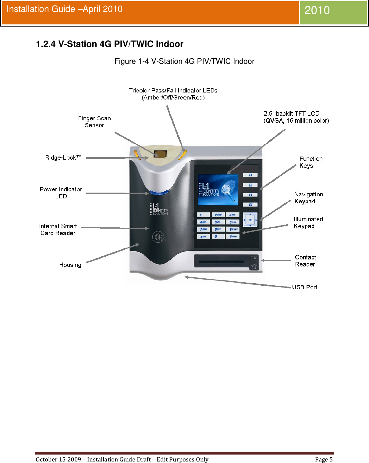
- 1. User Manual
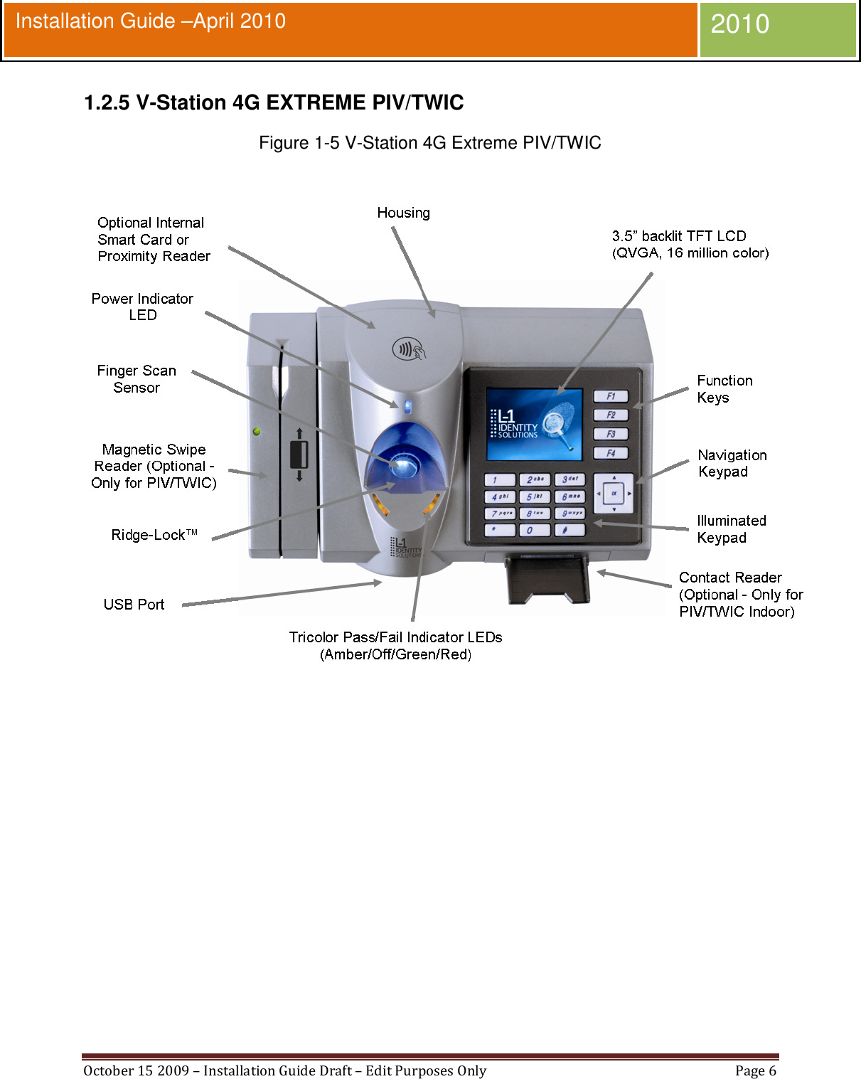
- 2. User Manual 2
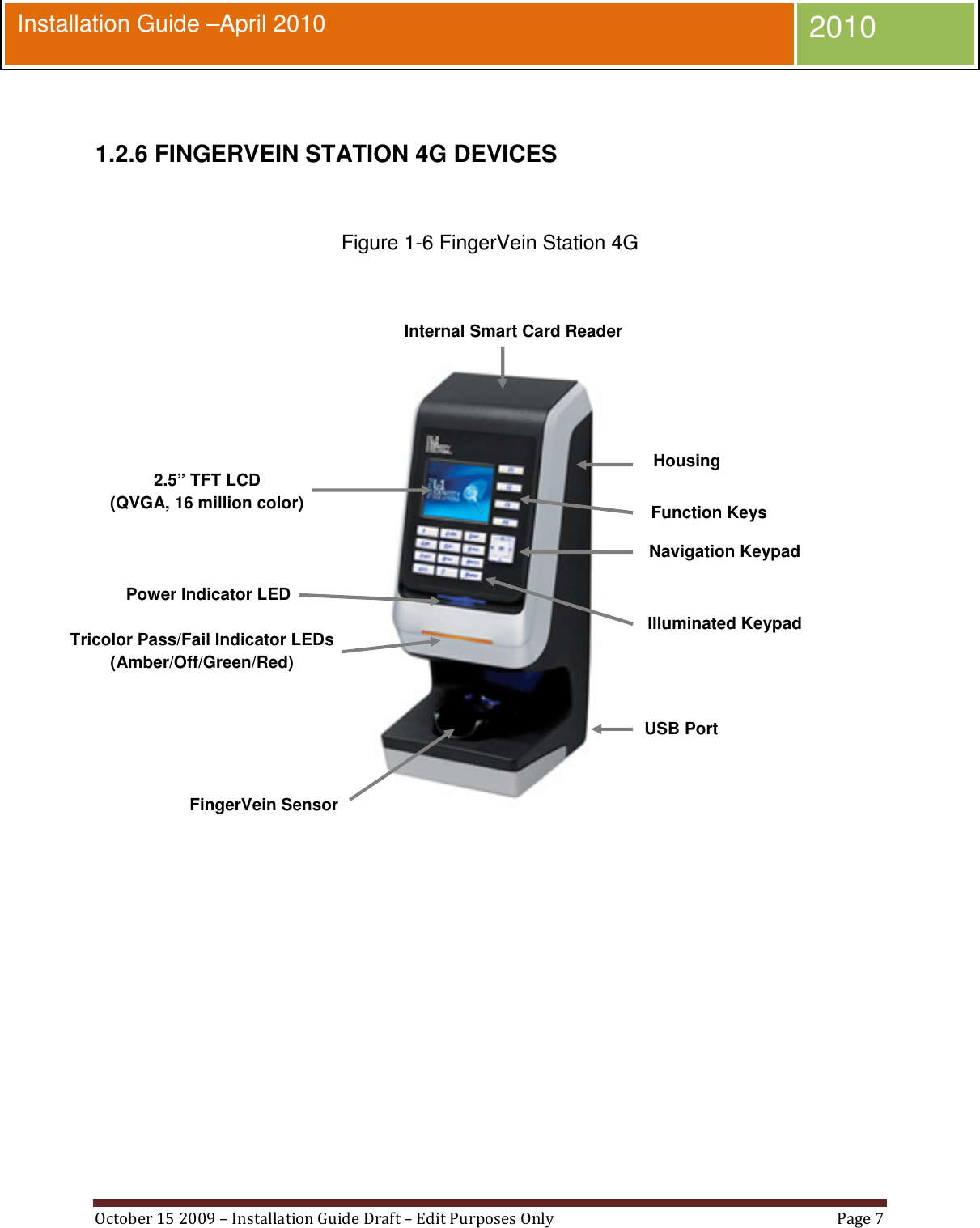
- 3. User Manual 1
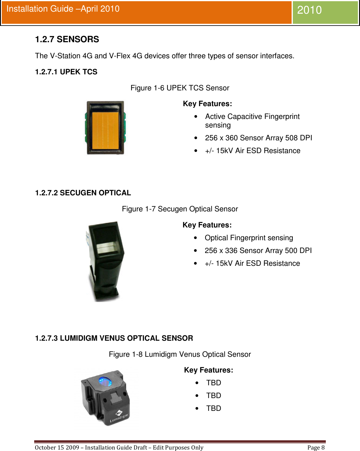
User Manual