Bioscrypt 4GFVSTPW FingerVein Access Control Accessory: 4G FingerVein Station User Manual Installation Manual Apr2010
Bioscrypt, Inc. FingerVein Access Control Accessory: 4G FingerVein Station Installation Manual Apr2010
Contents
- 1. User Manual
- 2. User Manual 2
- 3. User Manual 1
User Manual
October 15 2009 – Installation Guide Draft – Edit Purposes Only Page 1
Installation Guide –April 2010
2010
CHAPTER 1 - INTRODUCTION
CHAPTER OVERVIEW
This chapter provides an introduction to the V-Station 4G and V-Flex 4G devices, their
specifications and features, and safety guidelines that should be observed when using
or handling the devices.
1.1 INTRODUCTION
This manual provides step-by-step procedures for installing a L-1 Identity Solutions V-
Station 4G or V-Flex 4G device. It covers the entire process of physically installing the
device, making the necessary power, ground, and network connections, and registering
the device in SecureAdmin. Instructions for field repairs and cleaning are also provided.
1.1.1 SYMBOLS USED IN THIS GUIDE
The symbols shown below are used throughout this manual. They denote special issues
the user might encounter. Their definitions are given below.
DANGER
This symbol denotes a danger condition that may cause death or
excessive damage to property.
WARNING
This symbol denotes a warning condition that may cause severe
injury or major damage to property.
CAUTION
This symbol denotes a cautionary condition that may cause injury or
minor damage to property.
October 15 2009 – Installation Guide Draft – Edit Purposes Only Page 2
Installation Guide –April 2010
2010
NOTICE
This symbol denotes a situation needing additional advice to avoid
incorrect usage.
1.2 PRODUCT OVERVIEW
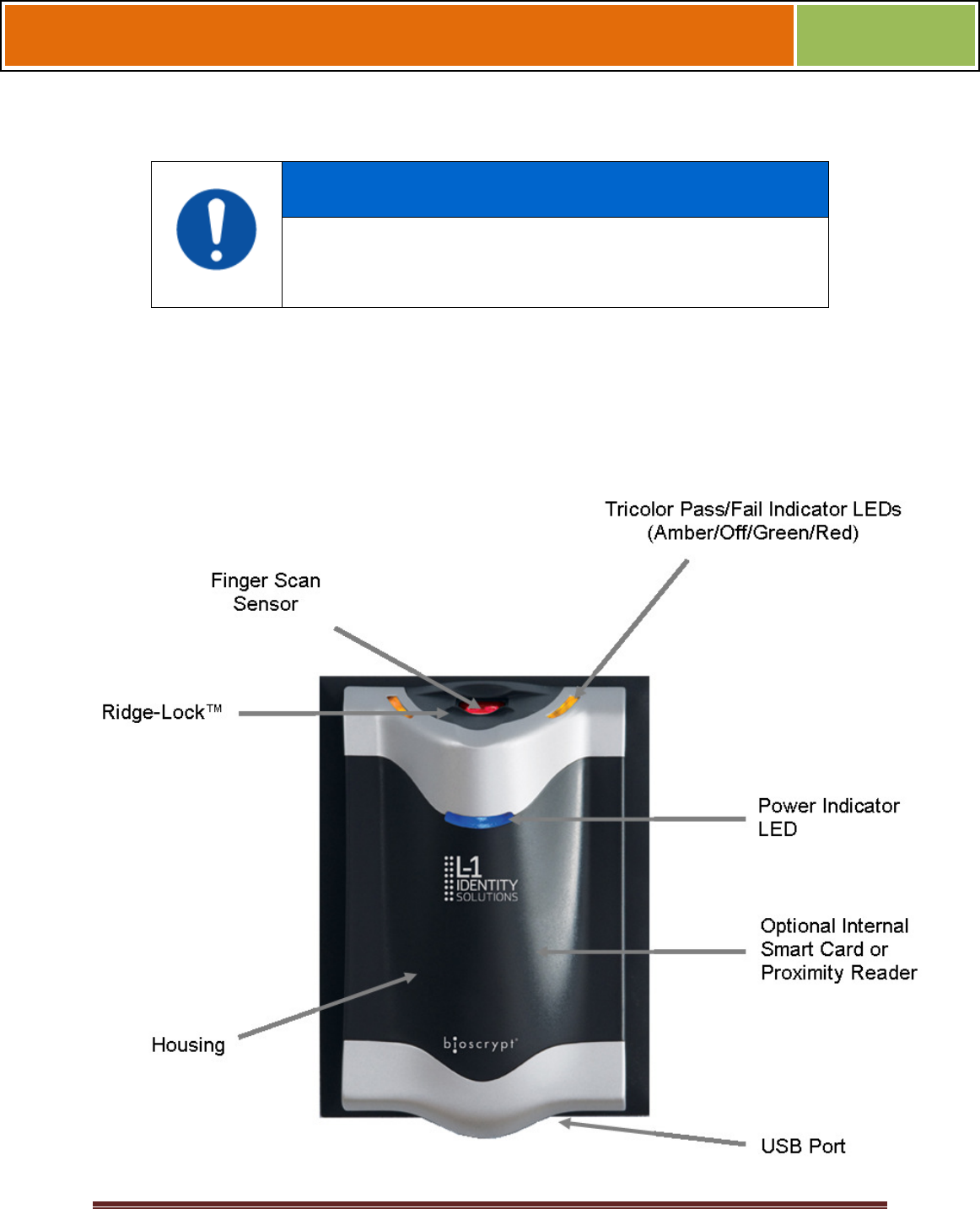
1.2.1 V-FLEX 4G
Figure 1-1 4G Flex Device
October 15 2009 – Installation Guide Draft – Edit Purposes Only Page 3
Installation Guide –April 2010
2010
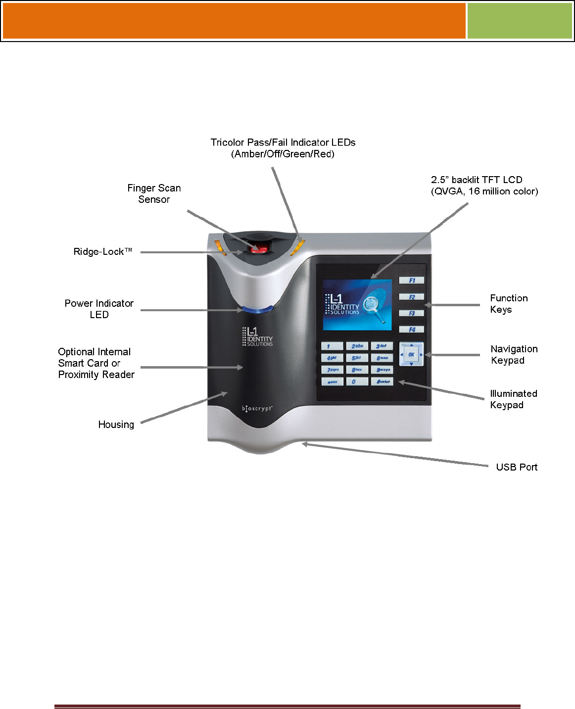
1.2.2 V-STATION 4G
Figure 1-2 V-Station 4G Device

October 15 2009 – Installation Guide Draft – Edit Purposes Only Page 4
Installation Guide –April 2010
2010
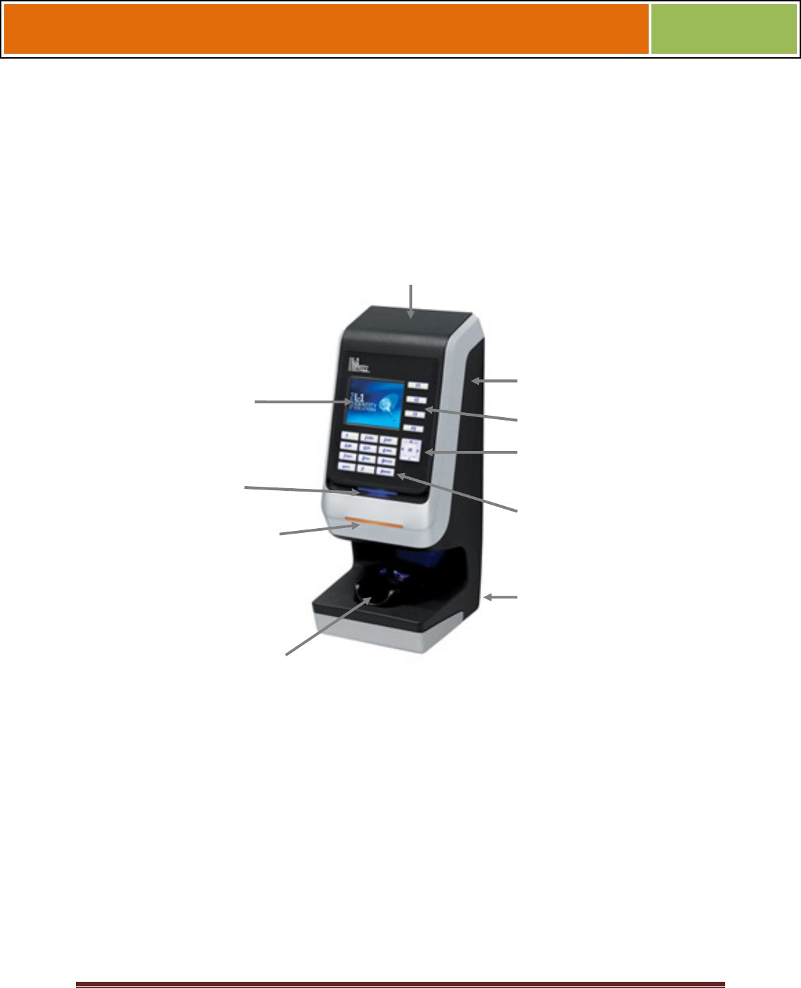
1.2.3 V-Station 4G EXTREME Device
Figure 1-3 V-Station EXTREME Device
October 15 2009 – Installation Guide Draft – Edit Purposes Only Page 5
Installation Guide –April 2010
2010
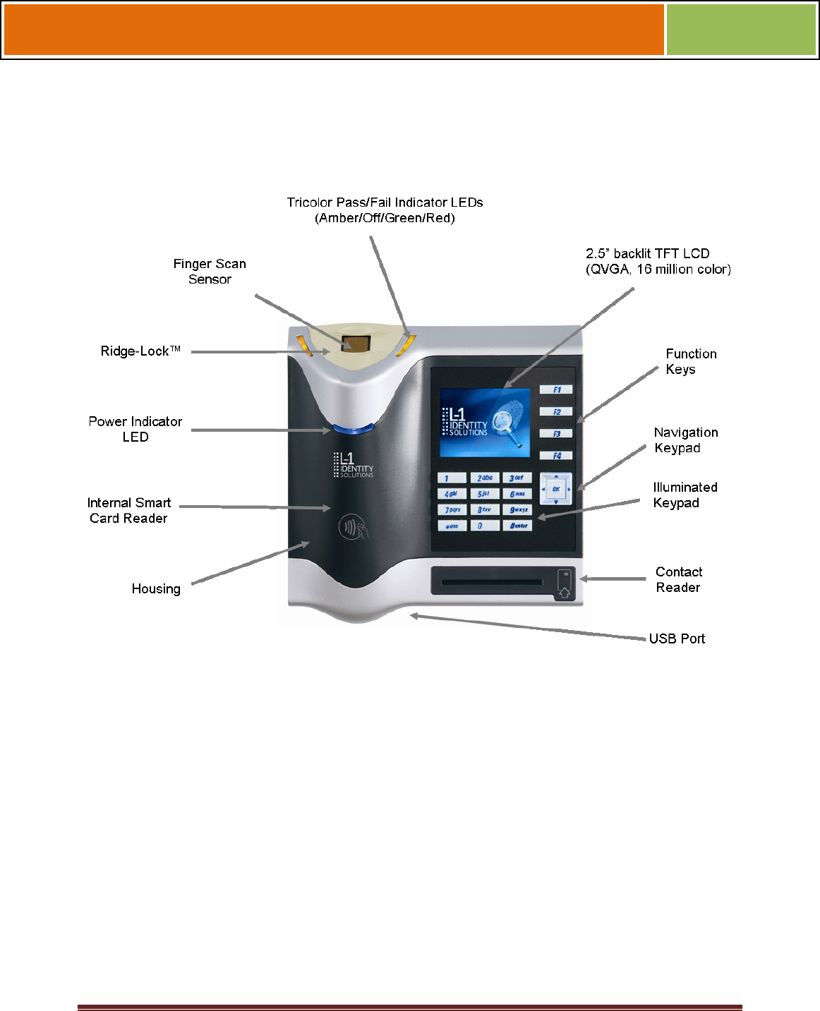
1.2.4 V-Station 4G PIV/TWIC Indoor
Figure 1-4 V-Station 4G PIV/TWIC Indoor
October 15 2009 – Installation Guide Draft – Edit Purposes Only Page 6
Installation Guide –April 2010
2010
1.2.5 V-Station 4G EXTREME PIV/TWIC
Figure 1-5 V-Station 4G Extreme PIV/TWIC
October 15 2009 – Installation Guide Draft – Edit Purposes Only Page 7
Installation Guide –April 2010
2010
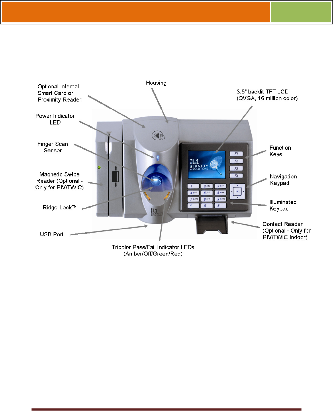
1.2.6 FINGERVEIN STATION 4G DEVICES
Figure 1-6 FingerVein Station 4G
Tricolor Pass/Fail Indicator LEDs
(Amber/Off/Green/Red)
Power Indicator
LED
FingerVein Sensor
Internal Smart Card Reader
2.5” TFT LCD
(QVGA, 16 million color)
Housing
USB Port
Illuminated Keypad
Navigation Keypad
Function Keys
October 15 2009 – Installation Guide Draft – Edit Purposes Only Page 8
Installation Guide –April 2010
2010
1.2.7 SENSORS
The V-Station 4G and V-Flex 4G devices offer three types of sensor interfaces.
1.2.7.1 UPEK TCS
Figure 1-6 UPEK TCS Sensor
Key Features:
• Active Capacitive Fingerprint
sensing
• 256 x 360 Sensor Array 508 DPI
• +/- 15kV Air ESD Resistance
1.2.7.2 SECUGEN OPTICAL
Figure 1-7 Secugen Optical Sensor
Key Features:
• Optical Fingerprint sensing
• 256 x 336 Sensor Array 500 DPI
• +/- 15kV Air ESD Resistance
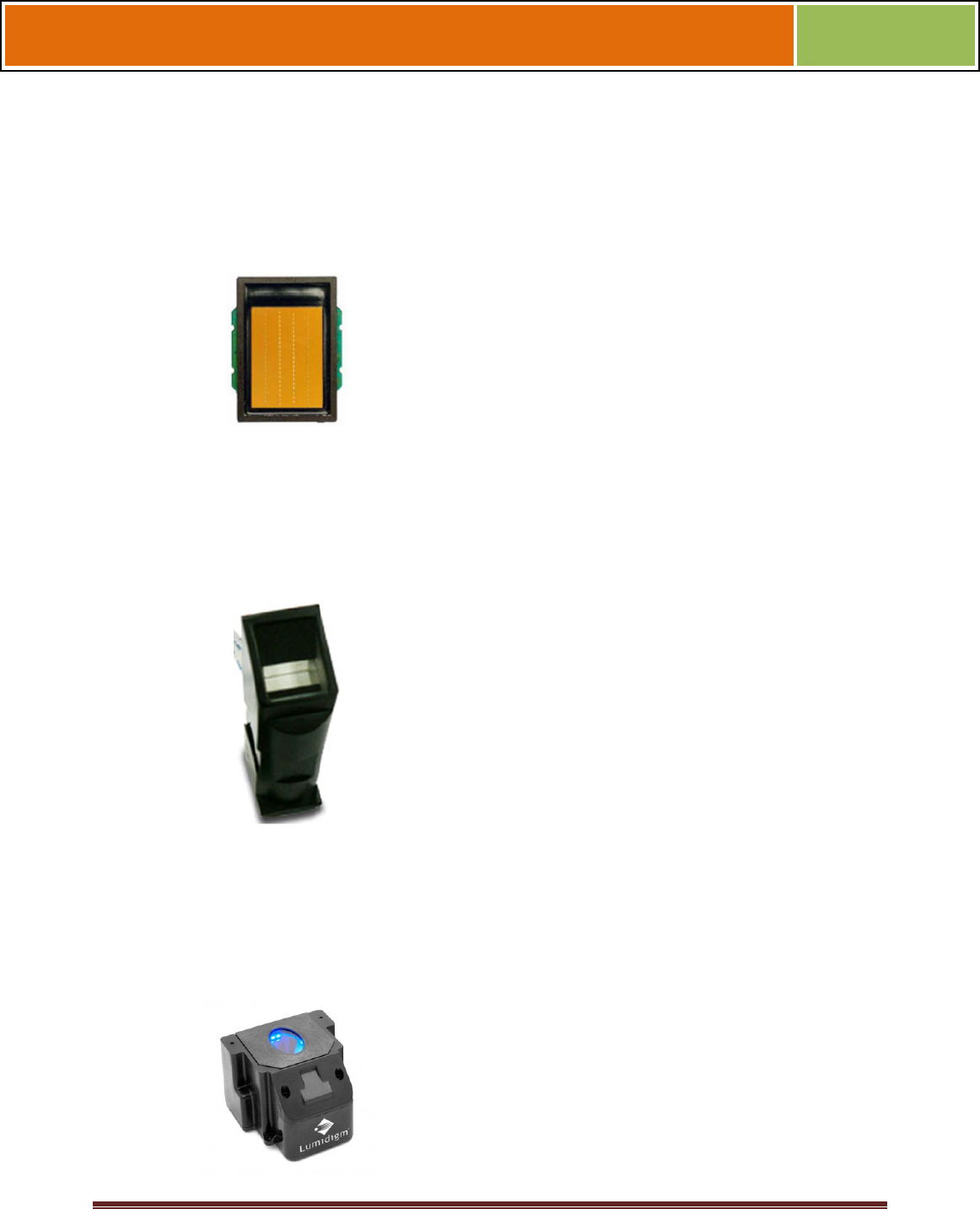
1.2.7.3 LUMIDIGM VENUS OPTICAL SENSOR
Figure 1-8 Lumidigm Venus Optical Sensor
Key Features:
• TBD
• TBD
• TBD
October 15 2009 – Installation Guide Draft – Edit Purposes Only Page 9
Installation Guide –April 2010
2010
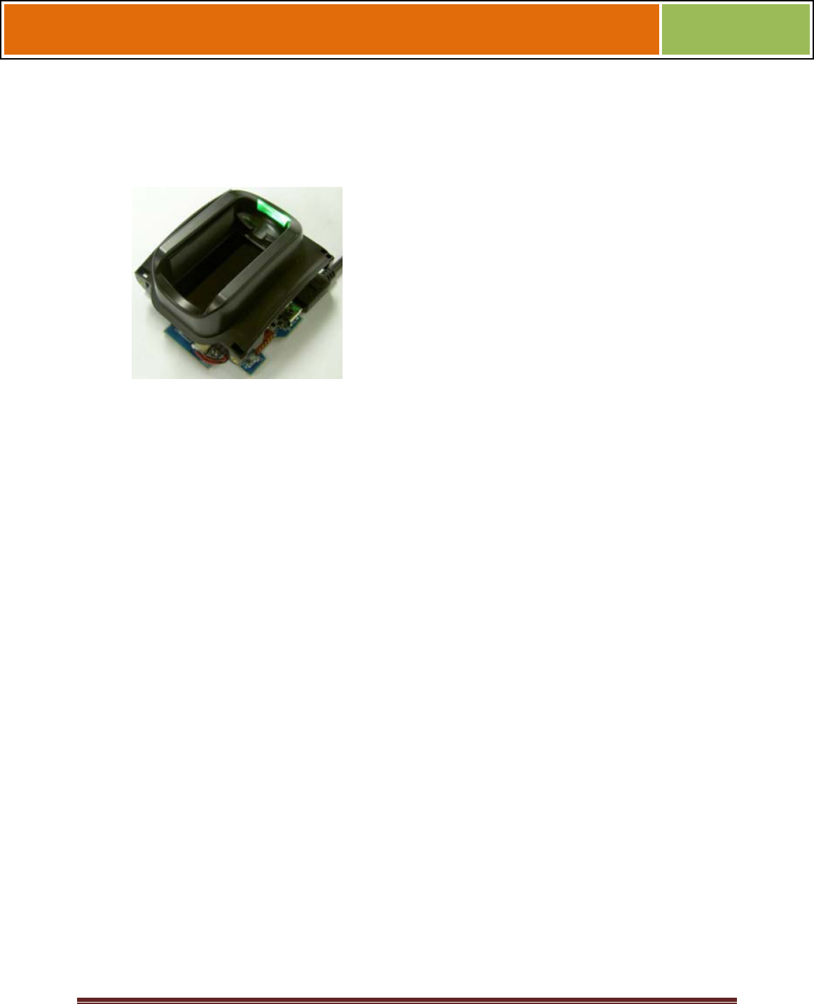
1.2.7.4 HITACHI FINGERVEIN SENSOR
Figure 1-9 Hitachi FingerVein Sensor
Key Features:
• TBD
• TBD
• TBD
October 15 2009 – Installation Guide Draft – Edit Purposes Only Page 10
Installation Guide –April 2010
2010
1.2.8 DEVICE DIMENSIONS
1.2.8.1 V-Flex 4G Device
Figure 1-9 V-Flex 4G Dimensions
October 15 2009 – Installation Guide Draft – Edit Purposes Only Page 11
Installation Guide –April 2010
2010
1.2.8.2 V-STATION 4G
Figure 1-10 V-Station 4G Dimensions
October 15 2009 – Installation Guide Draft – Edit Purposes Only Page 12
Installation Guide –April 2010
2010
1.2.8.3 V-STATION EXTREME PIV/TWIC DEVICES
1.2.8.3.1 V-STATION 4G EXTREME
Figure 1-11 V-Station 4G Extreme Dimensions
October 15 2009 – Installation Guide Draft – Edit Purposes Only Page 13
Installation Guide –April 2010
2010
1.2.8.3.2 V-STATION 4G EXTREME WITH ACCESSORIES
Figure 1-12 V-Station 4G Extreme with Accessories Dimensions
October 15 2009 – Installation Guide Draft – Edit Purposes Only Page 14
Installation Guide –April 2010
2010
1.2.8.3.3 V-STATION 4G EXTREME PIV/TWIC
Figure 1-13 V-Station 4G Extreme PIV/TWIC
October 15 2009 – Installation Guide Draft – Edit Purposes Only Page 15
Installation Guide –April 2010
2010
1.2.8.3.4 V-STATION EXTREME PIV/TWIC WITH ACCESSORIES
Figure 1-14 V-Station 4G Extreme PIV/TWIC with Accessories Dimensions
October 15 2009 – Installation Guide Draft – Edit Purposes Only Page 16
Installation Guide –April 2010
2010
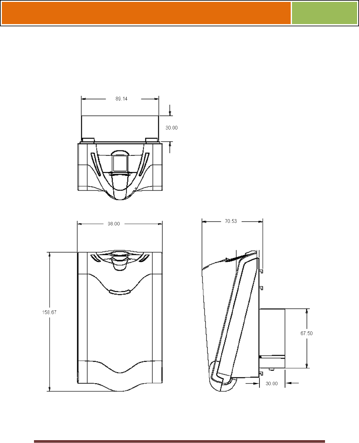
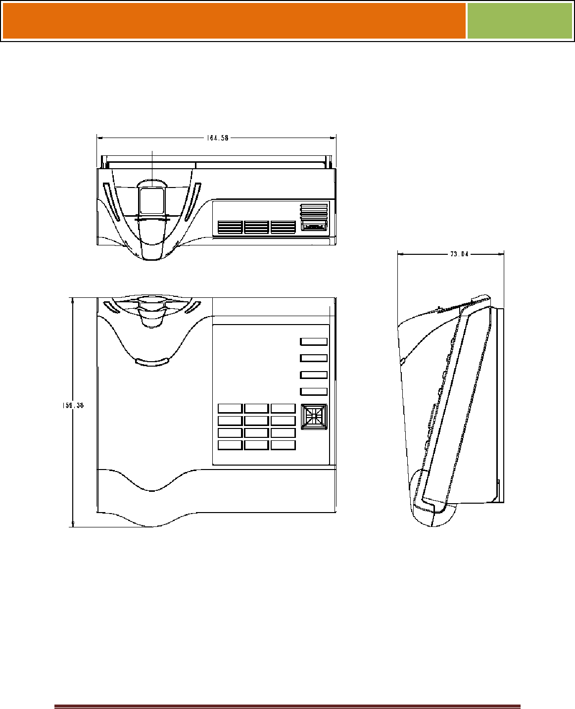
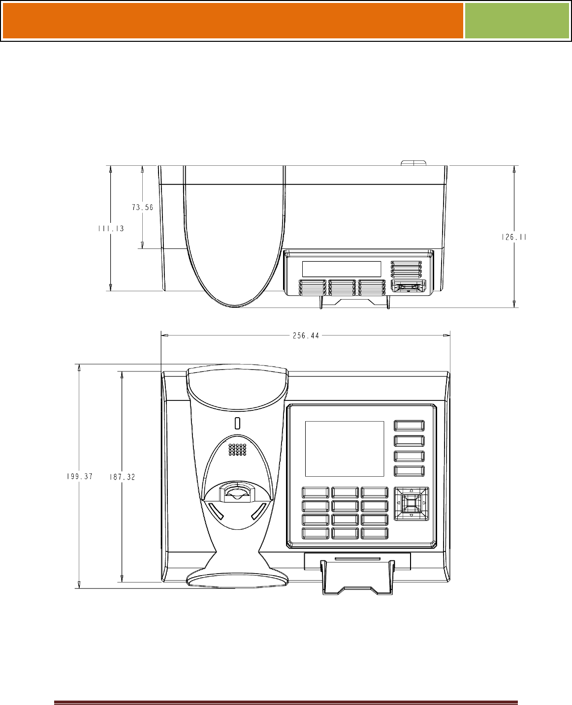
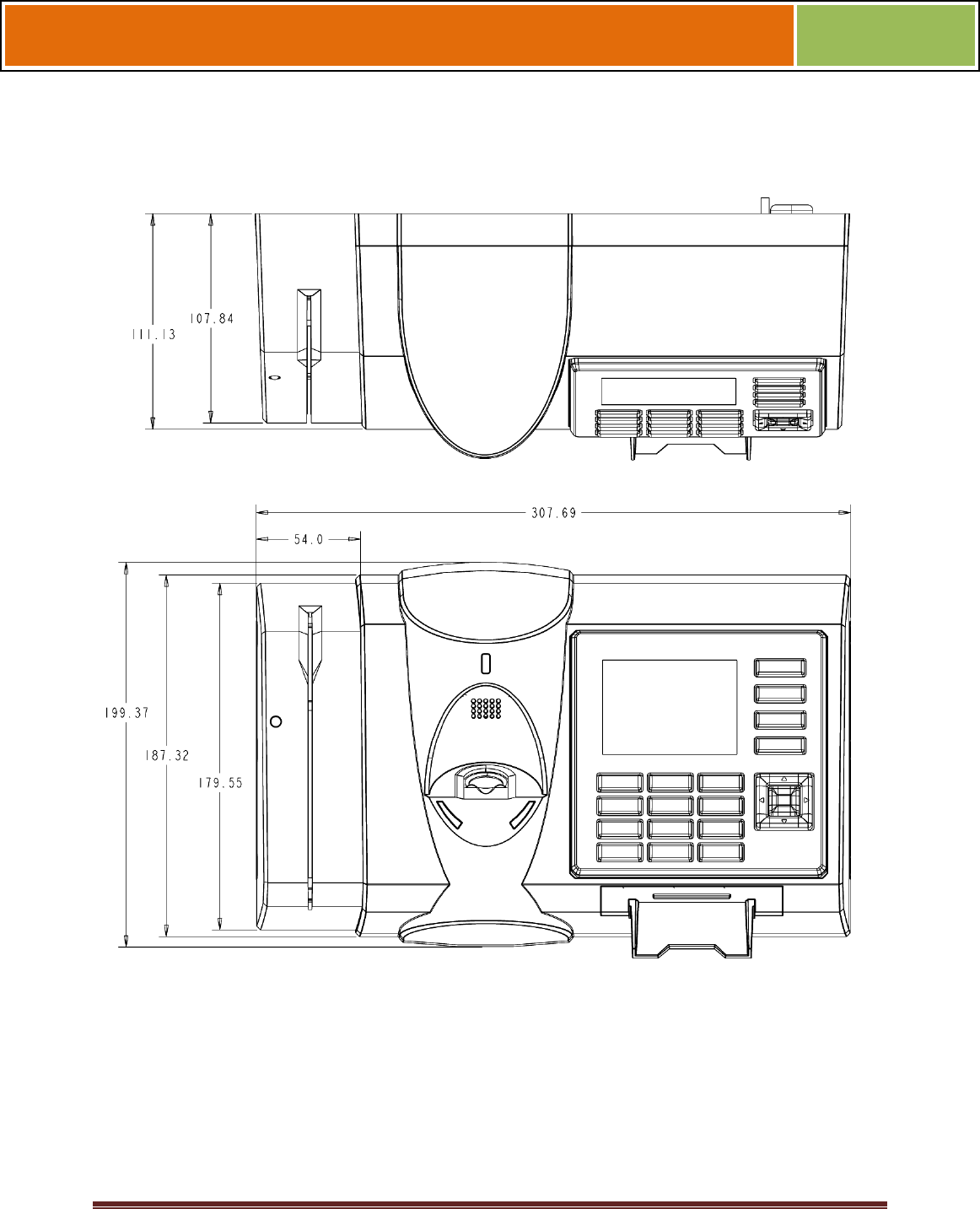
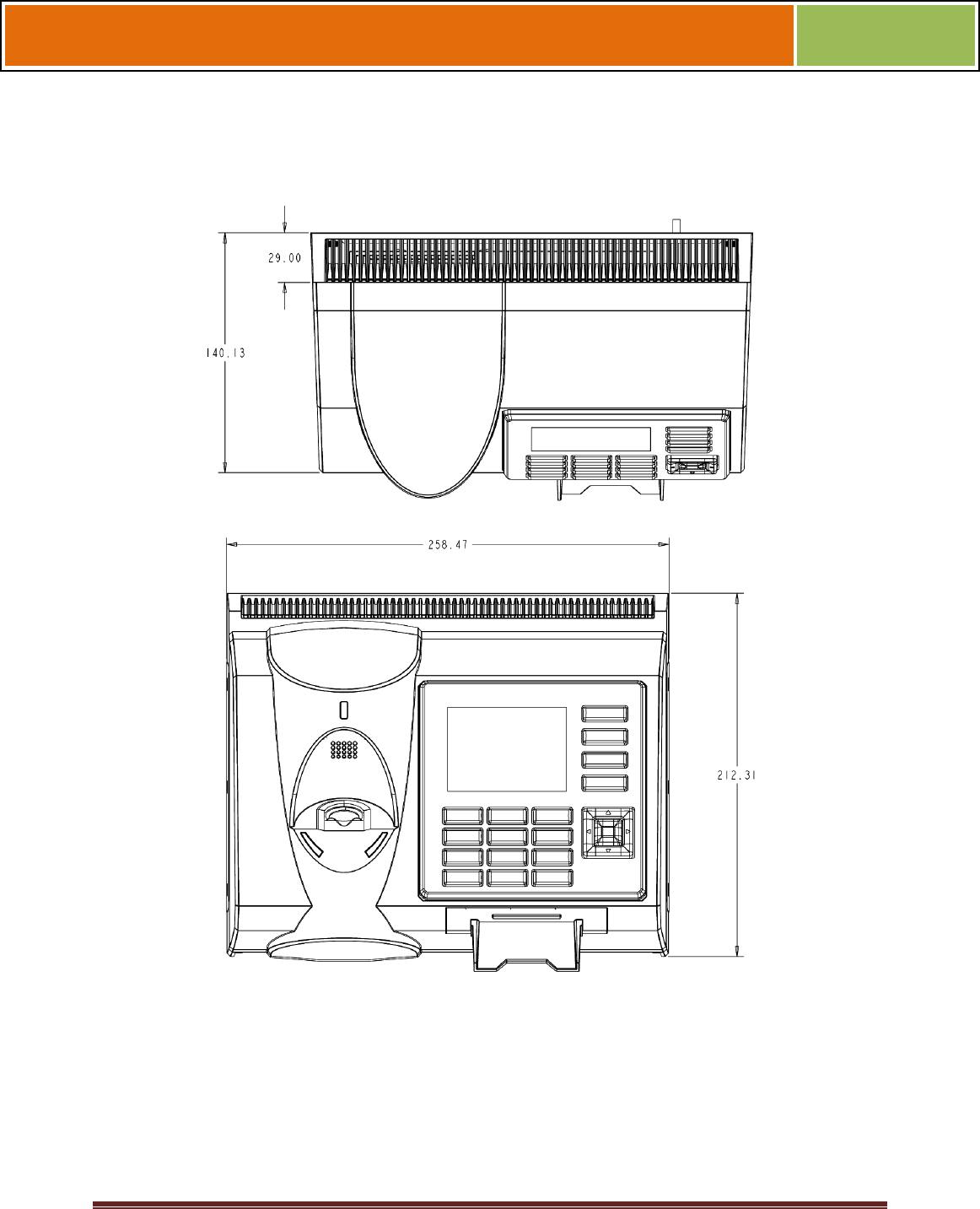
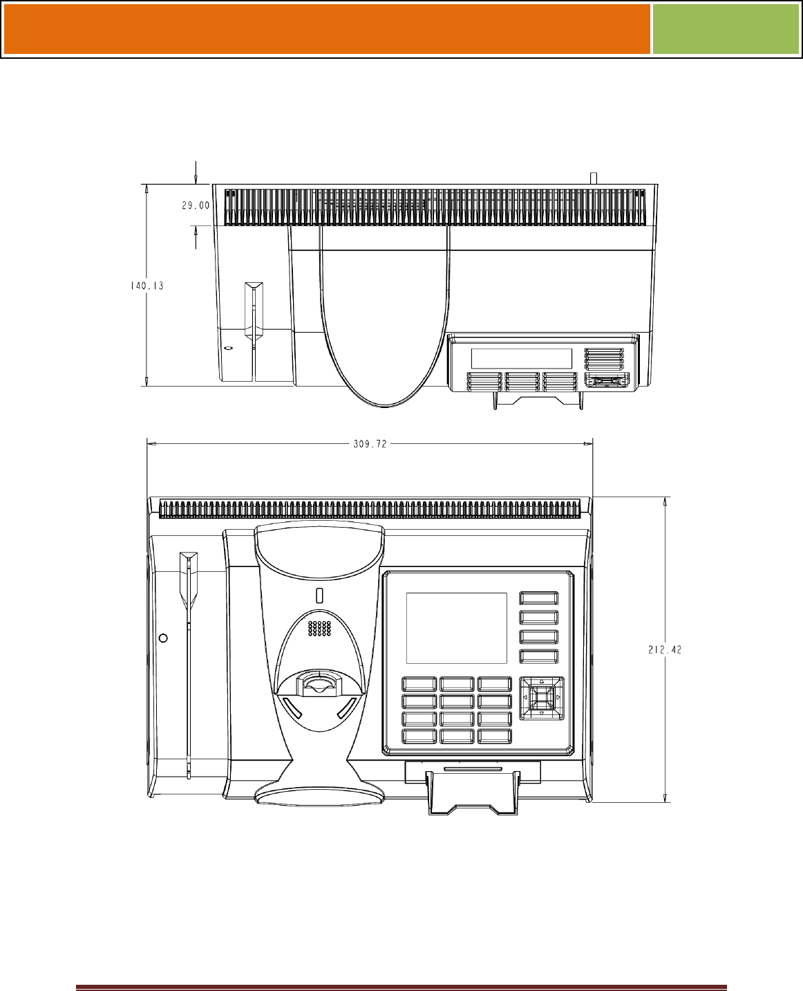
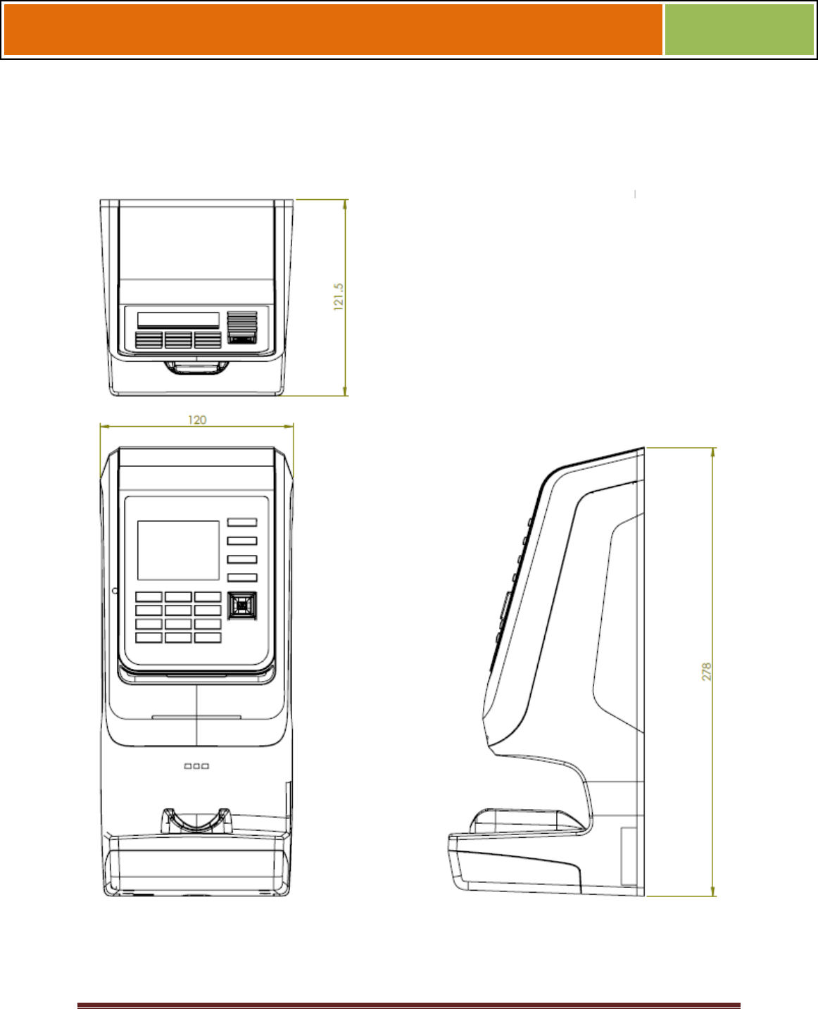
1.2.8.4 FINGERVEIN STATION 4G DEVICES
Figure 1-15 FingerVein Station 4G Dimensions

October 15 2009 – Installation Guide Draft – Edit Purposes Only Page 17
Installation Guide –April 2010
2010
1.2.9 SAFETY PRECAUTIONS
Below are safety precautions that should be observed when operating or installing a
device.
1.2.9.1 ELECTRO-STATIC DISCHARGE
L-1 Identity Solutions recommends that Administrators inform Users of these points
during the enrollment process:
Always use the Ridge-Lock to position a finger *before* touching the
sensor.
Always stand on the ESD-dissipative floor covering (if installed).
Do not touch other people or objects when touching the sensor.
Always maintain at least 12 inches of space around yourself when
touching the sensor.
Do not allow articles of clothing to touch the sensor.
L-1 Identity Solutions recommends that Installers always follow these points (in addition
to the points listed above):
When installing or working on a unit, always use a grounding wrist-
strap that is connected to a quality Earth ground.
Check the device's cabling for ground faults.
Ensure that the device's ground connection (located on the rear of the
device) is connected to a quality Earth Ground.
1.2.9.2 DEVICE HANDLING GUIDELINES
Do not install the device in locations where the device would be
exposed to direct sunlight, high levels of relative humidity, particulate
matter, or flammable vapors.
Do not install the device near radiators or other heat sources.
Do not allow magnetic objects to come within close proximity to the
device.
Strong magnetic fields might damage the device.
Do not let liquids Card the device.

October 15 2009 – Installation Guide Draft – Edit Purposes Only Page 18
Installation Guide –April 2010
2010
Do not attempt to alter the device for any reason.Modifications will
void the product guarantee.
Do not attempt to disassemble the device in any way beyond what is
necessary for sensor field replacement.
Do not use the device for any purpose other than for what it was
designed.
Do not plug any equipment into the USB port other than flash memory
devices.
Do not allow users to place or hang objects on the device, such as
coffee cups or purses.
Do clean the device regularly to remove dust, grime, and fingerprint
residue.

October 15 2009 – Installation Guide Draft – Edit Purposes Only Page 19
Installation Guide –April 2010
2010
CHAPTER 2 - PLANNING THE
INSTALLATION
CHAPTER OVERVIEW
This chapter details how to plan a successful installation, recommended steps, and
explains the hardware and software components of typical setup scenarios.
2.1 PLANNING THE INSTALLATION
Planning the installation is the single most important aspect of a successful installation.
In general, you need to consider the access controller, the door locks, the devices, and
the need for a network. By the time you are ready to install the system, all of the details
presented in the list below should be known. Take a moment to go through them now
before starting your installation.
During the planning phase, you should determine:
What type of authentication is required for your application?
How many doors need to be secured?
What type of device will be on each door? Doors already inside a
secure area might not need the same type or level of security.
If multiple V-Series 4G devices require networking for template
distribution/management, then a dedicated PC is recommended to
administer the system, as well as an RS-485 to RS-232 converter, and
cabling for serial communications or cabling for Ethernet.
Verify that the chosen access controller supports the Wiegand formats
supported by V-Station 4G devices.
Identify all wiring by the signal levels it is to carry. Use separate cables
and conduits for different signal groups to avoid cross talk. Plan to
separate them by these groups:
Power distribution: Wires carry power to devices, door strikes, etc.
Data communication: RS-485, RS-232, USB, Wiegand, Ethernet, etc.
Signal: Door contact, request-to-exit push button, alarm input, etc.
When planning device placement, determine the distance limitation of
each signal type and use repeaters if necessary.
October 15 2009 – Installation Guide Draft – Edit Purposes Only Page 20
Installation Guide –April 2010
2010
V-Series 4G devices are intended for indoor use only.
If you have any unresolved issues with the items on this list, contact L-1 Identity
Solutions Technical Support for additional information before beginning any installation.
WARNING
V-Station 4G and V-Flex 4G devices should be installed
by only a qualified technician. If you are not qualified to
perform an installation task, call L-1 Identity Solutions
Technical Support or contact a qualified installer
.
2.1.1 RECOMENDED STEPS FOR A SUCCESSFUL INSTALLATION
Every installation is unique. Sometimes the issues are well defined and can be handled
in a standard fashion; sometimes the issues are very specific and may not be
immediately recognizable.
L-1 Identity Solutions recommends following these steps for a successful installation:
Plan the installation Choose the type of hardware required, decide if a
network is required, and decide on the location and number of required
devices.
Unpack all items Unpack all items and check against the packing list.
Install network hardware components Install the cabling and
components needed to run the system.
Install software Install the software needed to set up the devices.
Preconfigure device Connect the device to the USB cable, supply
power to the device, and preconfigure the device.
Mount devices Mount the devices in their final locations
Power distribution and device hook up Connect the device wiring via
the back panel.
Power-up procedure Check the power connections and start the
system safely. Enroll users Enroll users into the system (for user
enrollment procedures).
Chapters 3 through 7 in this document present more information on these steps.

October 15 2009 – Installation Guide Draft – Edit Purposes Only Page 21
Installation Guide –April 2010
2010
2.1.2 REQUIREMENTS
PC workstation with:
1 GHz Intel(r) Pentium(r) 4 processor or equivalent
1 GB RAM (2 GB recommended)
CD-ROM drive
One available COM port or USB port
Ethernet card
Display: 1024 x 768 high color (minimum)
Regulated DC Power supply
Door controller
TCP/IP network environment
RS-232 to RS-485 converter with power supply (for advanced
administrative features).
2.1.2.1 HARDWARE REQUIREMENTS
Deadbolt/door strike
Snubber diode required to protect regulated DC power supply from
inductive kickback(1 N4007 diode or equivalent recommended)
Separate power supply for the deadbolt/door strike based on supplier's
recommendations.
External relay (if required)
Networking cable
2.1.2.2 COMPUTER REQUIREMENTS
2.1.2.2.1 SECURE ADMIN SERVER REQUIREMENTS
Hard disk space: 10 MB
2.1.2.2.2 SECUREADMIN CLIENT REQUIREMENTS
Hard disk space: 25 MB http://2.2.2.3.microsoft.net/

October 15 2009 – Installation Guide Draft – Edit Purposes Only Page 22
Installation Guide –April 2010
2010
2.1.2.2.3 MICROSOFT .NET FRAMEWORK 3.5 SP1 REQUIREMENTS
Hard disk space: Up to 600 MB might be required
2.1.2.2.4 SUPPORTED OPERATING SYSTEMS
SecureAdmin Server and SecureAdmin Client support these operating systems:
Windows Server 2003 R2
Windows Server 2008
Windows Vista
Windows XP Service Pack 2 or higher
2.1.2.2.5 SQL SERVER 2008 EXPRESS EDITION
Hard disk space: 350 MB of available hard-disk space for the
recommended installation. Approximately 425 MB of additional
available hard-disk space for SQL Server Books Online, SQL Server
Mobile Books Online, and sample databases.
During installation of SQL Server 2008, Windows Installer creates
temporary files on the system drive. Before running setup to install or
upgrade SQL Server, verify that at least 2.0 GB of disk space is
available on the system drive for these files
Actual Hard Disk Space Requirements: 280 MB for the recommended
installation.
2.1.2.2.6 ORACLE 10G EXPRESS
Hard disk space:
Server component: 1.6 GB Client component: 75 MB
2.1.2.3 NETWORK REQUIREMENTS
The V-Station 4G and V-Flex 4G devices function on 100 baseT
networks.
2.1.2.4 SOFTWARE REQUIREMENTS
Both SecureAdmin Server and SecureAdmin Client require these software applications
as prerequisites:
.net Framework 3.5
Windows Installer 4.5

October 15 2009 – Installation Guide Draft – Edit Purposes Only Page 23
Installation Guide –April 2010
2010
If these applications are not already installed, they will get installed during the setup
process.
SecureAdmin Server and SecureAdmin Client also require System Administrator access
to install the application.
SecureAdmin uses a self-signed certificate (x.509 certificate) with a file extension of
.pfx.
You have the option of installing your own certificate, which must be purchased from a
recognized authority in advance. The SecureAdmin self-signed certificate is installed
only with the SecureAdmin server component. No certificate is installed with the
SecureAdmin client component, and during the client installation, you are asked to
specify which type of certificate SecureAdmin server will be using (the self-signed
certificate provided with the SecureAdmin server component installation or a signed
certificate from another authority such as VeriSign.
2.1.3 UNPACK EQUIPMENT
Unpack all items and check against the packing list.
2.1.3.1 PARTS LIST
2.1.3.1.1 V-STATION 4G or V-FLEX 4G DEVICES
Hardware
1 V-Station 4G or V-Flex 4G device
1 Wall mounting plate/mullion mounting plate
6 #6-32 3/4" Philips pan-head screw
6 #6 1" Philips pan-head self-tapping screws
6 #4-8 1" nylon wall anchors
29 Crimp connector, B Wire (RoHS)
2 6-32 security screw, pin-in hex, 3/8
2 0.013" ID, 3/8" OD, 1/32" thick, fiber washers
1 Ethernet ferrite core
1 DC & I/O lines ferrite core
1 External power cable
1 External signal cable

October 15 2009 – Installation Guide Draft – Edit Purposes Only Page 24
Installation Guide –April 2010
2010
1 Micro-USB device cable
1 Micro-USB PC cable
Tools
1 1/8" pin-in-hex security key 2.5
2.1.3.1.2 V-STATION 4G EXTREME DEVICES
Hardware
1 V-Station Indoor or Outdoor 4G device
29 Super B-Wire Connectors, Dolphin DC-100-S
2 dielectric grease (maybe 1 is enough, need to try out)
1 Cable, User Wiegand, 4G Outdoor
8 wall mount anchor, conical, for #8 screws
1 8-32x11/32"UNC K-Lot Hex nut RoHS
1 8-32-MALE-FEMALE-HEXSTAND-1.25L
1 mech, AS101001_ACTUATOR_MAGNET
8 #8x1" thread forming screw, pan head, philips,
6 6-32 Security Screw 1/8" pin-in-hex 3/8" length
1 Stainless Steel, Wall Mount Plate with Magnetic Reader, 4G
Outdoor
1 Cable, MicroUSB PC, NGV
1 Cable, MicroUSB Device, NGV
1 Cable, User Comm and Ctrl, 4G Outdoor
1 Cable, User TTL, 4G Outdoor
2.1.3.1.4 FingerVein STATION 4G
Hardware

October 15 2009 – Installation Guide Draft – Edit Purposes Only Page 25
Installation Guide –April 2010
2010
1 FingerVein Station 4G
1 Wall mounting plate/mullion mounting plate
8 #6-32 3/4" Philips pan-head screw
8 #6 1" Philips pan-head self-tapping screws
8 #4-8 1" nylon wall anchors
29 Crimp connector, B Wire (RoHS)
2 6-32 security screw, pin-in hex, 3/8
2 0.013" ID, 3/8" OD, 1/32" thick, fiber washers
1 Ethernet ferrite core
1 DC & I/O lines ferrite core
1 External power cable
1 External signal cable
1 Micro-USB device cable
1 Micro-USB PC cable
Tools
1 1/8" pin-in-hex security key 2.5
2.1.3.1.4 DOCUMENTATION
1 Installation Guide (on Installation CD)
1 Operator's Manual (on Installation CD)
1 Quick Start Guide (on Installation CD and printed copy in package)
Documentation for your new device is installed onto your computer when you install the
SecureAdmin software. The product documentation is also available online at:
http://www.l1id.com/pages/450-product-manuals
The documentation is provided in Adobe Acrobat format (PDF). The Adobe Acrobat
Reader application is available on the Installation CD or at: http://www.adobe.com
October 15 2009 – Installation Guide Draft – Edit Purposes Only Page 26
Installation Guide –April 2010
2010
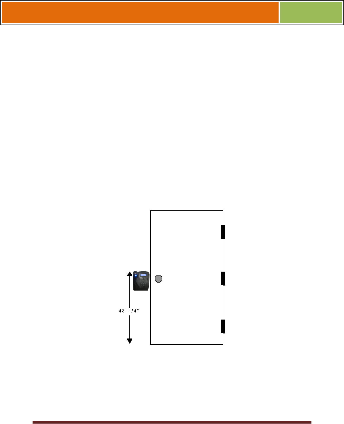
2.1.4 CHOOSING THE INSTALL LOCATION
V-Station 4G and V-Flex 4G devices are designed to mount on either a double-gang
electrical box or on any flat surface. Consult with local professionals regarding any
building and safety codes that might affect your installation. The correct mounting height
is shown below.
Factors to consider when determining the position of a device on the wall:
Proximity to other switch plates or fixtures (the device should ideally be
mounted in-line with other plates or fixtures)
Distance from the floor to the top of the device (L-1 Identity Solutions
recommends using a height between 48 and 54 inches).
The device should be mounted on the knob-side of the door
Compliance with the Americans with Disabilities Act if in the United
States. Information about http://www.usdoj.gov.
Figure 2-1 Correct Mounting Height
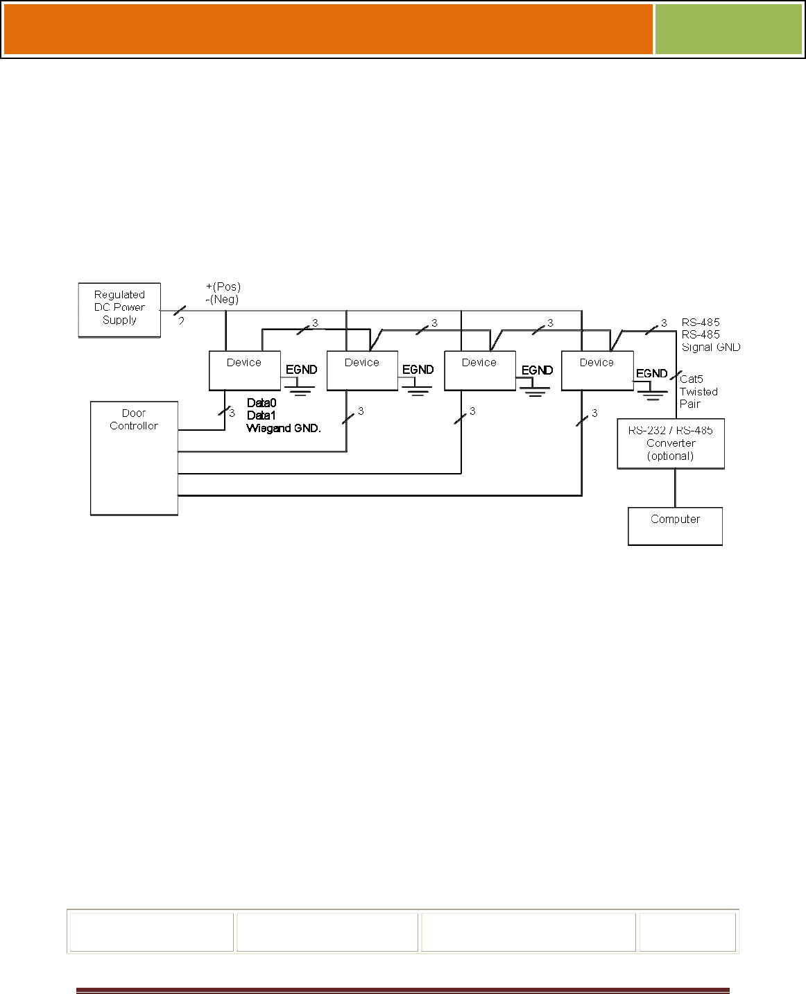
2.1.5 PLAN DEVICE NETWORK
The 4G devices feature a built-in single-door relay that allows them to control a single
door lock. They can therefore function on their own or as part of a larger access control
system.
October 15 2009 – Installation Guide Draft – Edit Purposes Only Page 27
Installation Guide –April 2010
2010
System component selection is specific to each installation, but a minimum system
would consist of a finger-scan device mounted on or near an access point, an electric
lock, and cabling.
A more complex system might consist of devices at multiple access points (each with an
electric door lock), a multi-point controller, networking, and a PC to run the access
controller and SecureAdmin Server software.
See the diagram below for an example (non-Ethernet) system diagram.
Figure 2-2 Example RS-485 System Diagram
Installation of locks and access controllers should be completed according to their
respective manufacturers' specifications and in accordance with all local codes. Final
connections to the device are explained in more detail in Chapter 4.
To avoid externally generated transients, do not run any wires near utility AC power
wiring, lightning rod grounding wire, etc. Grounding equipment is required for ESD
protection and safety.
2.1.6 CHOOSE NETWORK TYPE
If your installation requires the use of network communications, then the choice of
cable, the cable run length, the network topology, and the termination of the network are
important aspects that must be considered. The V-Station 4G and V-Flex 4G devices
can be networked using RS-232, RS-485, or Ethernet protocols.
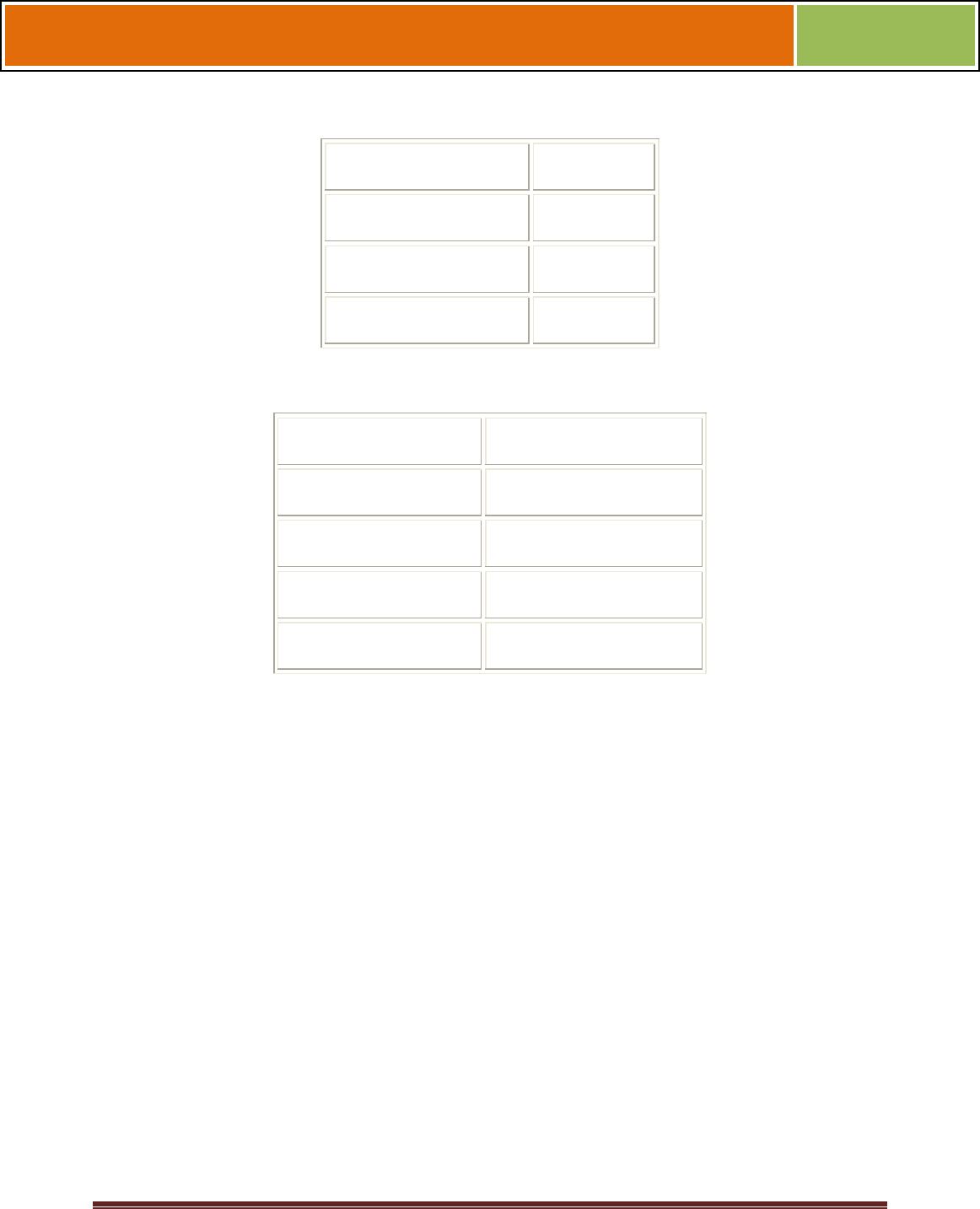
The table below outlines relevant parameters of the RS-485, RS-232, and 100 baseT
Ethernet communication protocols.
Table 2-1 Communications Network Comparison
Spec RS-485 RS-232 100BaseT
October 15 2009 – Installation Guide Draft – Edit Purposes Only Page 28
Installation Guide –April 2010
2010
Spec RS-485 RS-232 100BaseT
Mode of Operation Differential DC Coupled Single-ended DC Coupled Multi
DC Isolation No No No
Maximum Distance 4000 feet 150 feet 330 feet
Number of Devices
on one line
31 1 Unlimited
Maximum Data Rate 56 Kbps
(recommended)
56 Kbps* (recommended) Auto-
negotiated
2.1.6.1 RS-232
If your system has only one device, or a few devices (each only a short distance away
from the SecureAdmin PC) then RS-232 can be used, provided that each device can
have a dedicated RS-232 port.
With RS-232 at 9600 baud, a distance of 150 feet is possible with shielded cable, but at
56 Kbps, a maximum of only 20 feet is recommended.
2.1.6.2 RS-485
RS-485 has two distinct advantages over the more common RS-232. First, it allows you
to connect up to 31 4G devices to a PC with an external RS-232 to RS-485 converter
(available from L-1 Identity Solutions). Second, the RS-485 specification allows for
cable
run lengths up to 4000 feet (1200 meters) at modest baud rates.
An RS-485 network is required instead of RS-232 if:
Multiple devices must be connected together so that templates can be
distributed among the devices
The installation has only a single device, but it is over 150 feet (45
meters) from the host PC.
2.1.6.2.1 RS-485 CABLE SPECIFICATION
V-Station 4G devices provide a 2-wire, half-duplex RS-485 interface. The main cable
run should be low capacitance, twisted-pair cable, with approximately 120 -ohm
characteristic impedance. Category-5 rated communications cable is used in RS-485
networks and its characteristics are defined below. This is the recommended cabling for
October 15 2009 – Installation Guide Draft – Edit Purposes Only Page 29
Installation Guide –April 2010
2010
RS-485 communications. The cable connection includes a differential line (+ and -) and
a GND connection.
Table 2-2 Category 5 Cable Characteristics
Specification Recommendation
Capacitance (conductor to conductor)
<20 pF/ft.
Characteristic Impedance 100 - 120 ohms
Nominal DC resistance <100 ohms/1000 ft.
Wire gauge 24 AWG stranded
Conductors/Shielding >2 pair (shielding is recommended)
2.1.6.2.2 RS-485 CABLE LENGTHS
As outlined in the RS-485 specification, the total length of the communication cable
(adding up all of the segments of the run) should not exceed 1200 meters (4000 feet).
Although the RS-485 specification calls for a maximum cable length of 1200 meters and
provides a maximum baud rate well above that of the 4G device, a more conservative
system should be configured to no more than 1000 meters and run at a baud rate of
9600 bits per second. After the network is configured and is running in a stable manner,
the baud rate can be increased if faster network communications are desired.
Drops (down-leads, stubs, T-connections, etc.) to equipment are not recommended, but
if required, should not exceed one foot) and should use the same cable recommended
above. On a long stub, a signal that travels down the wire reflects to the main line after
hitting the input impedance of the device at the end. This impedance is high compared
with that of the cable and the net
effect is degradation of signal quality on the bus.
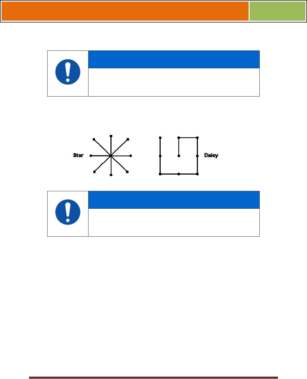
2.1.6.2.3 RS-485 NETWORK TOPOLOGY
Communication cables for RS-485 should be laid out in a daisy chain configuration (See
Figure 2-3 below). Long stubs or drop downs and the star configuration should be
avoided because they create discontinuities and degrade signal quality. The star
configuration usually does not provide a clean signaling environment even if the cable
runs are all of equal length. The star configuration also presents a termination problem,
because terminating every endpoint overloads the driver. Terminating only two
endpoints solves the loading problem, but creates transmission line problems at the
unterminated ends. A true daisy chain configuration avoids these problems.
October 15 2009 – Installation Guide Draft – Edit Purposes Only Page 30
Installation Guide –April 2010
2010
NOTICE
The device on the end of the network should be
terminated with a 120 ohm resistor
.
Figure 2-3 Network Topologies Star and Daisy Chain Configurations
NOTICE
A Daisy configuration is recommended over a Star configuration..
2.1.6.3 ETHERNET
If your system is to be configured for use over Ethernet, the wiring will be slightly
different. Communication cables for Ethernet logically form a straight line bus but the
more devices on that bus, the less efficient the network becomes due to increased
collisions, and the weaker the signal will get over distance. Repeaters can be used to
boost the signal strength; however, a better solution is to place switches at intermediate
positions along the bus. The most common Ethernet topology in use today is the star
configuration with a hub or switch in the center.
2.1.6.4 WIRELESSNETWORK DESIGN CONSIDERATIONS
A wireless network of V-Station 4G offers several advantages over wired networks,
such as convenience, speed of installation, and less wiring. If you
are planning to design a wireless network, consider these points:
Wireless signal interference Metal masses such as HVAC ducts, fire doors, vents,
stairs, etc. disrupt wireless signals. Building and stairwell structures, as well as internal

October 15 2009 – Installation Guide Draft – Edit Purposes Only Page 31
Installation Guide –April 2010
2010
building walls, also impede wireless signals. Some electrical equipment, such as
microwaves, large-screen TVs, cordless telephones are also known to affect wireless
signals. Consider the proximity of devices to these objects.
Distance from access points How far a device is from the closest access point plays a
major factor in determining the stability and strength of the wireless signal.
Multiple Access Points "Repeaters" or multiple access points can solve signal strength
problems that may be caused by either distance or loss due to interference.
2.1.7 CHOOSE POWER SOURCE
V-Station 4G and V-Flex 4G devices can be powered by several methods:
1 2V DC regulated adapter/bullet jack (4G Indoor only)
Power Over Internet (POE) through an inline PoE 802.3af power
injector
Power Over Internet (POE) through an inline PoE36U-1AT-R power
injector (4G Extreme with heater only)
2-pin mini connector with dedicated power source (4G Indoor only)
3-wire cable (4G Extreme).
Power sources should be:
Isolated from other equipment
Filtered
Protected by an Uninterruptible Power Supply (UPS) or battery backup
Protected by a voltage suppression device if transient electrical surges
are an issue in the location.
When planning a system, know the power requirement of each device. If multiple
devices are to share a common power supply, exercise care to avoid excessive voltage
loss on the wires. Voltage loss can lead to communication problems when devices are
talking and/or listening on different ground references.
Voltage loss is directly proportional to wire resistance and the current the wire carries.
Always place the device as close as possible to the power supply and always select a
wire size appropriate for the load. V-Station 4G devices run on DC power between 12.5
and 24 VDC.
Power requirements for all V-Station 4G and V-Flex 4G models are listed below.
October 15 2009 – Installation Guide Draft – Edit Purposes Only Page 32
Installation Guide –April 2010
2010
Table 2-3 V-Station 4G, V-Flex 4G and FingerVein Station 4G Power Requirements
Power Requirement: 12 watts
Input Voltage Range: 12-24.0 VDC
Peak Current (12 VDC)
1 A
Peak Current (24 VDC)
500 mA
Table 2-4 V-Station 4G Extreme Power Requirements
Power Requirement 12 watts
Input Voltage Range 12-24.0 VDC @ 3 Amps
Peak Current (12 VDC)
1 A
Peak Current (24 VDC)
500 mA
Cooler Module 12 to 24VDC @ 10Amps
Most power supplies on the market today provide good input and output isolation.
However, power supplies which do not provide isolation (or have high leakage
capacitance), coupled with accidental AC power line interchanges, present serious
ground fault problems for installers. With a ground fault, the signal reference between
subsystems may be 115 VAC apart. If these subsystems are interconnected, the large
potential difference can cause equipment damage or personal injury. L-1 Identity
Solutions recommends using a dedicated regulated DC power supply.
All factory-supplied power supply assemblies are either switching or regulated linear
supplies and are isolated for safety and to minimize ground loop problems.
October 15 2009 – Installation Guide Draft – Edit Purposes Only Page 33
Installation Guide –April 2010
2010
CHAPTER 3 - INSTALL SOFTWARE
CHAPTER OVERVIEW
This chapter shows how to install, repair, modify, upgrade, and uninstall the
SecureAdmin Server and Client software packages.
3.1 INSTALL SOFTWARE
To install the SecureAdmin software, the user must have Administrator rights. Any
software required to install SecureAdmin is detected and installed automatically during
the setup process.
3.1.1 SECUREADMIN SERVER
To install the SecureAdmin Server software, follow these steps:
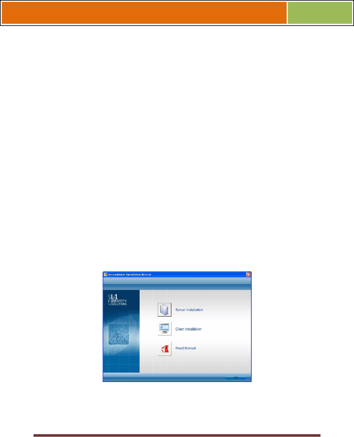
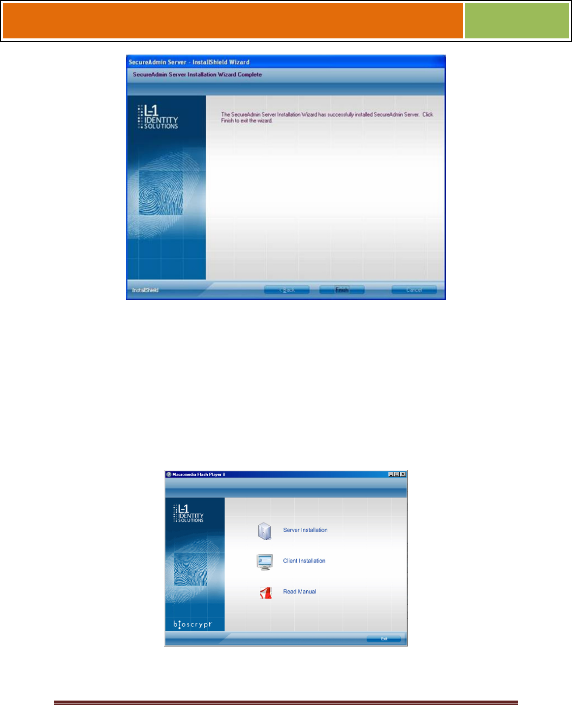
Insert the CD into the optical drive. If Autoplay is enabled, the installation process will
start automatically. A menu is displayed. If Autoplay is not enabled, start the
installation process manually by doubleclicking the Setup.exe file located in the
"Bioscryptsetup" folder on the root of the CD.
Figure 3-1 Install Menu
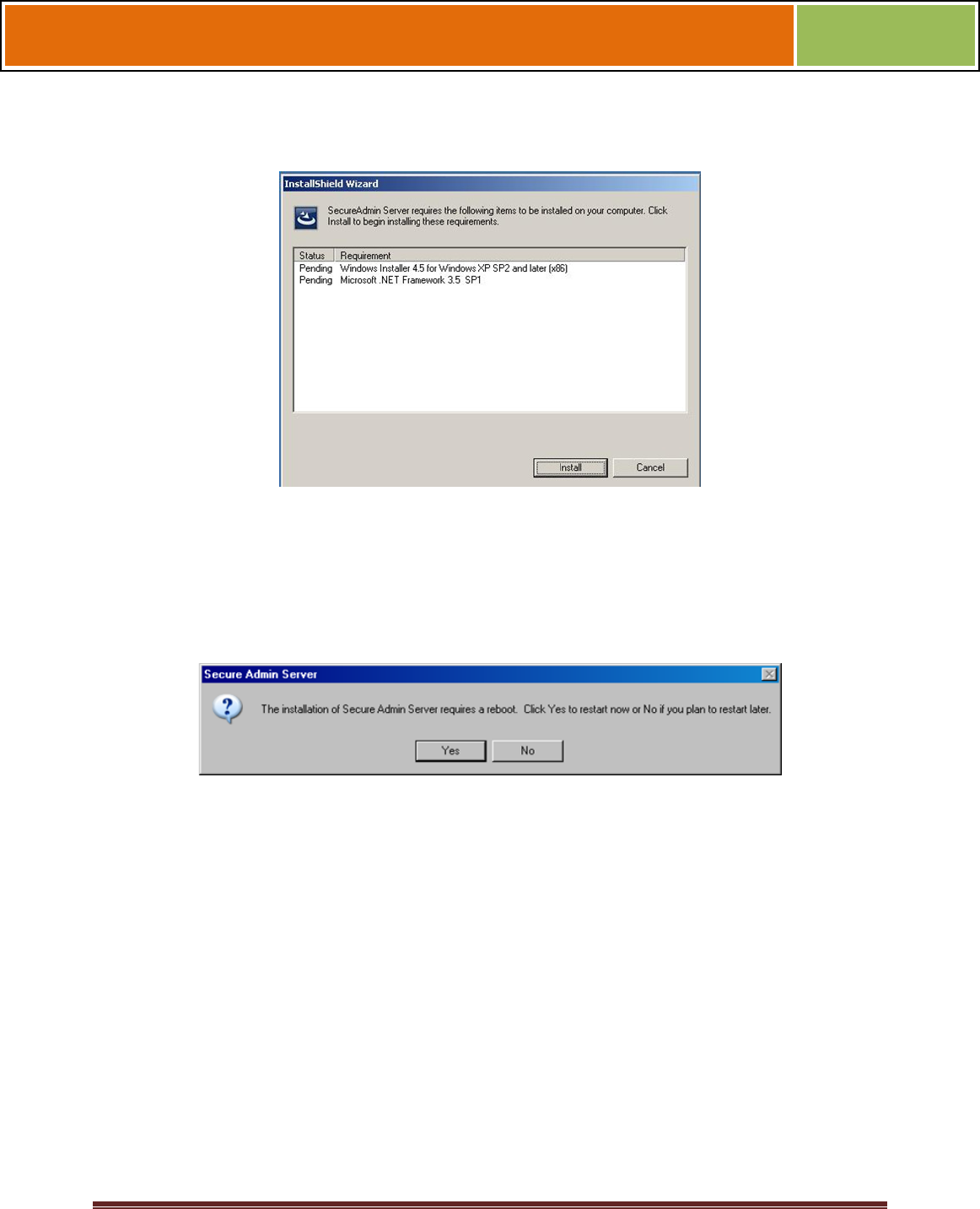
Click Server Installation. The InstallShield Wizard starts and the target system is
examined for prerequisite software. Any necessary software is listed.
October 15 2009 – Installation Guide Draft – Edit Purposes Only Page 34
Installation Guide –April 2010
2010
Figure 3-2 Prerequisites
Click Install . Microsoft .NET Framework 3.5 SP1 is installed. Restart the computer
when asked. The installation process continues automatically after the computer is
restarted. Repeat the same process for Windows Installer 4.5.
Figure 3-3 Restart Message
October 15 2009 – Installation Guide Draft – Edit Purposes Only Page 35
Installation Guide –April 2010
2010
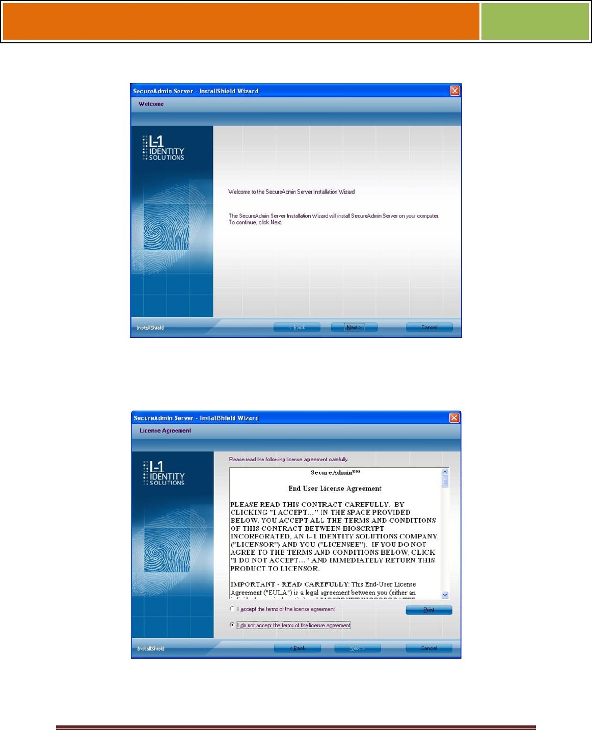
Figure 3-4 SecureAdmin Server Installation Wizard
The Secure Admin Server Installation Wizard is displayed. Click Next to continue the
setup process.
Figure 3-5 SecureAdmin Server License Agreement
The L-1 Identity Solutions License Agreement is displayed. Select the appropriate radio
button to agree with the terms and then click the Next button (You must accept the
terms of the licence agreement to continue the installation process).
October 15 2009 – Installation Guide Draft – Edit Purposes Only Page 36
Installation Guide –April 2010
2010
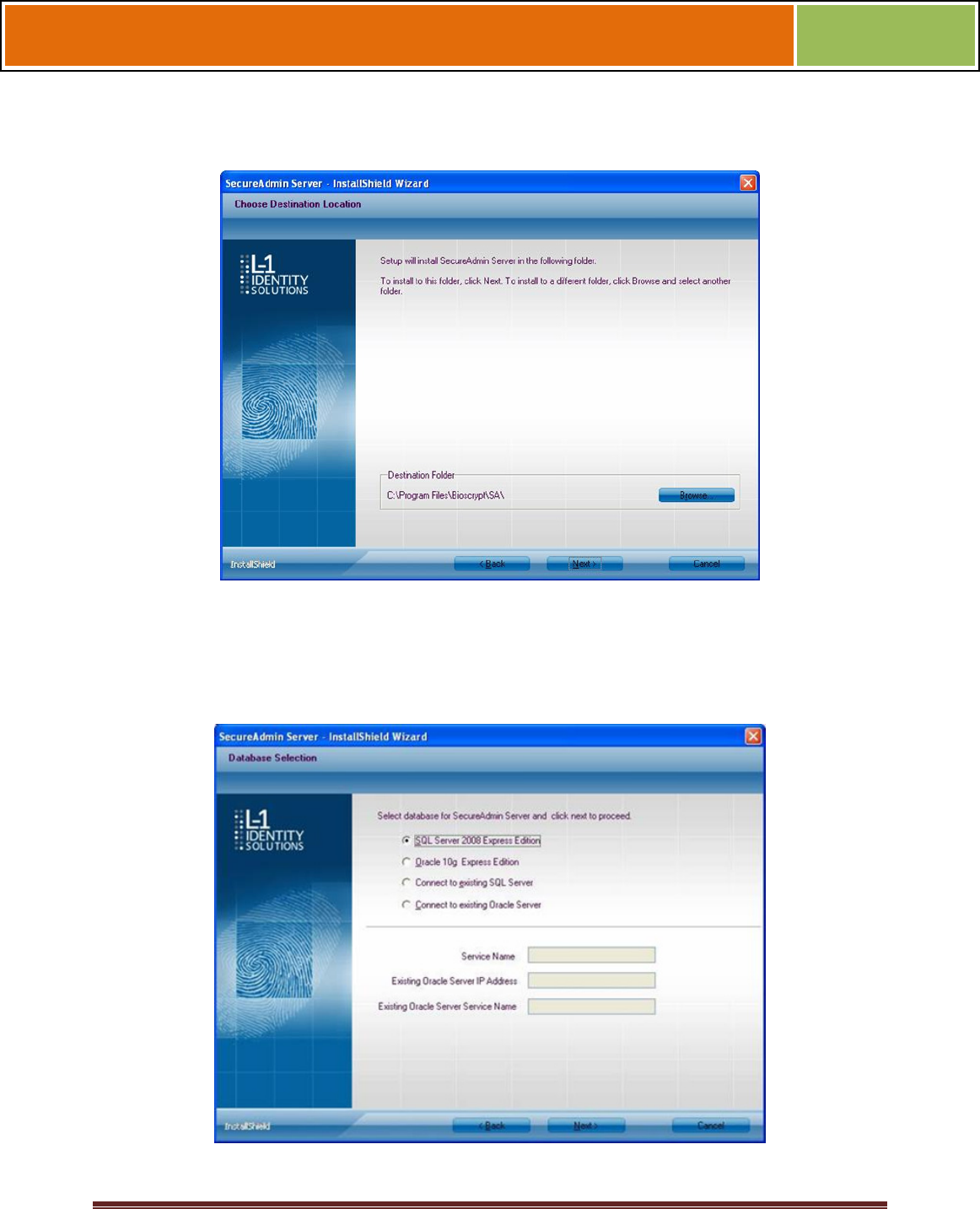
Figure 3-6 SecureAdmin Server Choose Destination Location
The Choose Destination Location screen is displayed. Accept the default installation
folder and click the Next button or click Browse to choose your own installation path.
After you specify a destination folder, the Database Selection screen is displayed.
Figure 3-7 Database Selection
October 15 2009 – Installation Guide Draft – Edit Purposes Only Page 37
Installation Guide –April 2010
2010
Using the radio buttons, select the type of database application you intend to work with,
or select an existing database. Click the Next button.
If you selected the SQL Server 2008 Express Edition option, it will be installed locally if
it is not already installed.
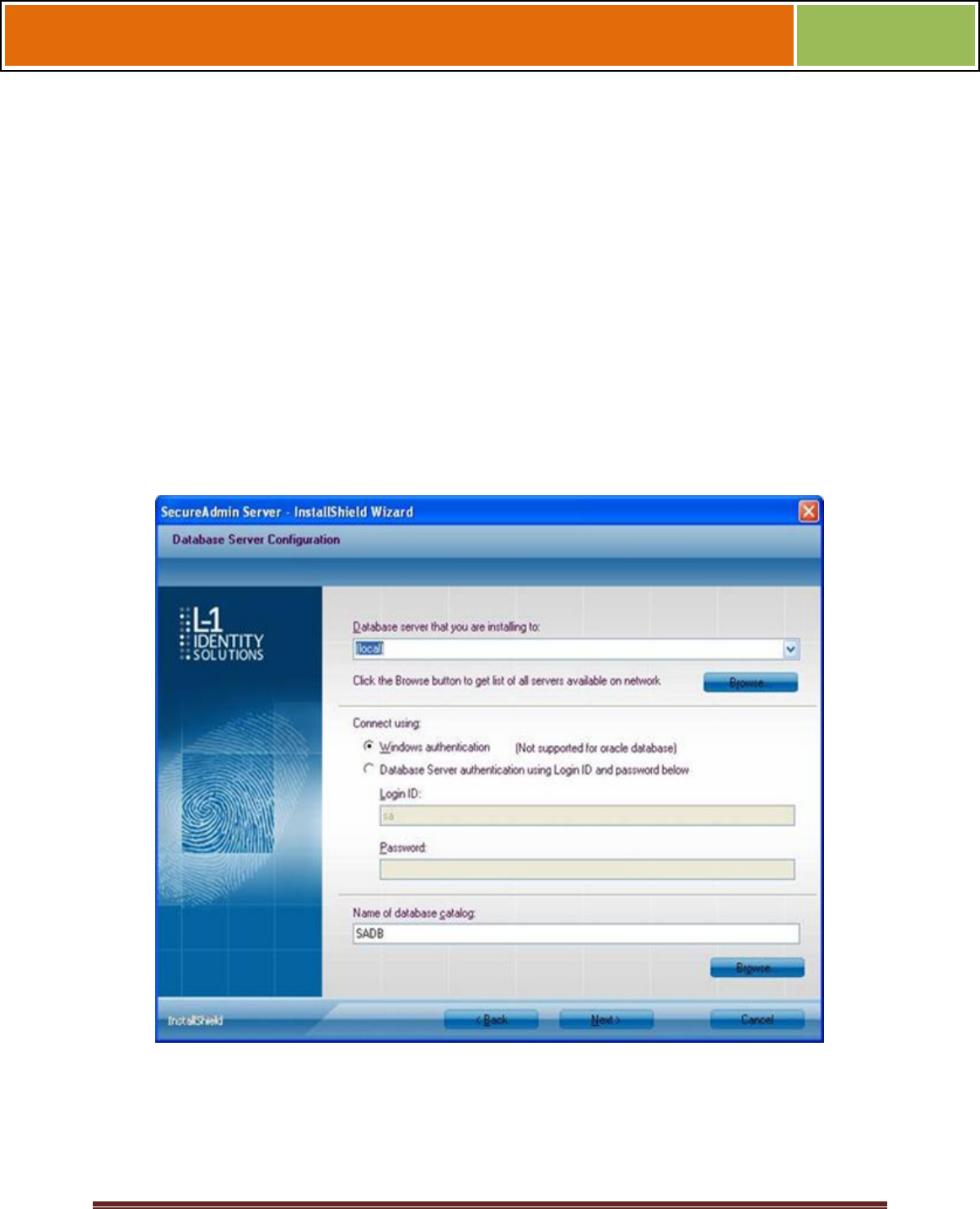
Select SQL Server 2008 Express Edition option to install SQL Server
2008 on the local machine and Click Next.
Select Windows authentication or Database server authentication
option and enter a valid login ID and password values.
Enter the name of the database catalog or click Browse to select an
existing database catalog.
Click Next to continue.
Figure 3-8 Connecting to SQL Server option
If you selected Connect to Existing SQL Server option,
Select Connect to Existing SQL Server option and Click on Next.

October 15 2009 – Installation Guide Draft – Edit Purposes Only Page 38
Installation Guide –April 2010
2010
You can select existing database instance of SQL Server 2005 or SQL
Server 2008 as required from the drop-down of Database server that
you are installing to.
Select the Database server authentication option and enter valid
Login ID and password values.
Accept the default database catalog or click Browse to select a
different database catalog.
Click Next to continue
If you selected the Oracle 1 0G Express Edition option, it will be installed locally if it is
not already installed.
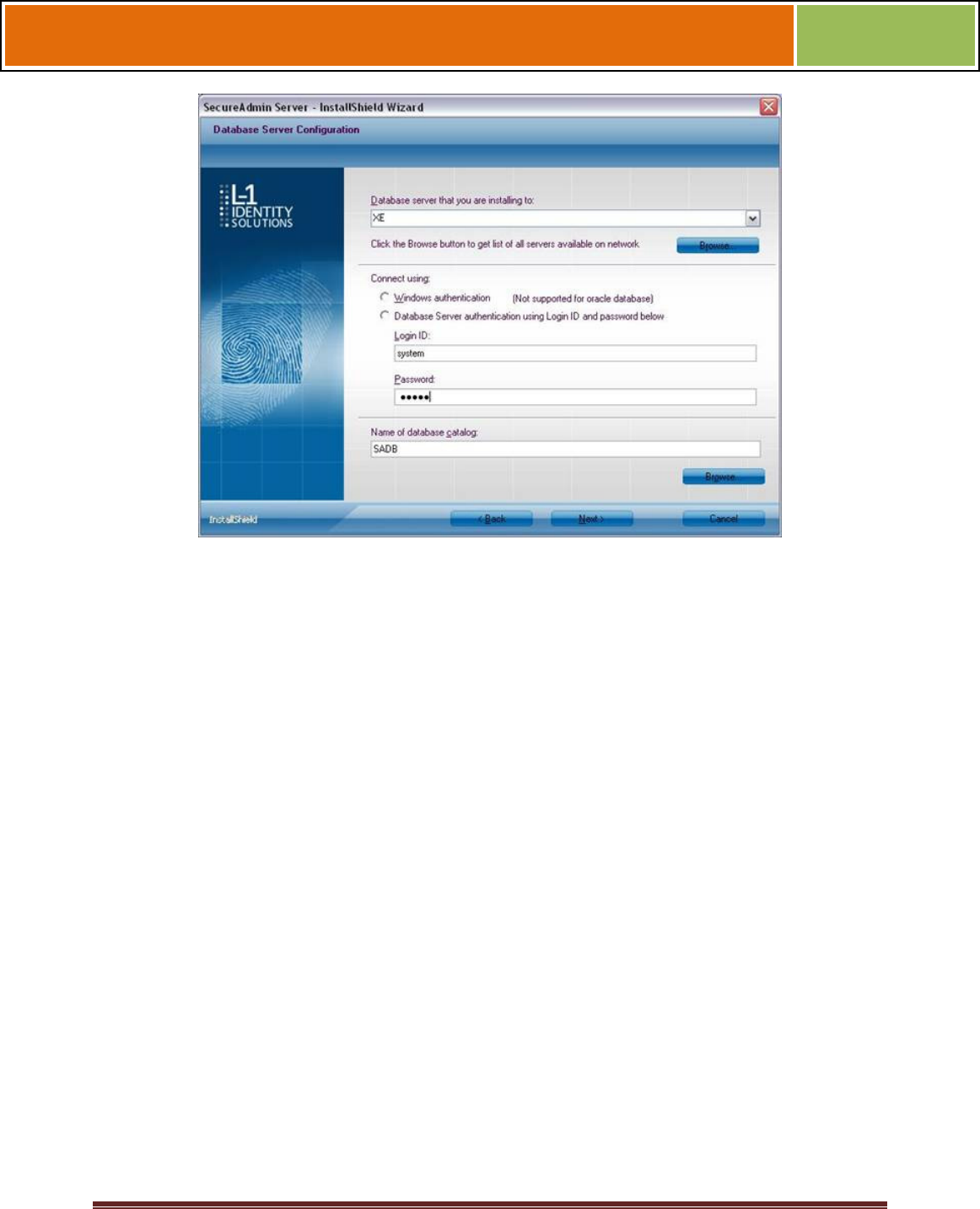
If you selected Connect to Existing Oracle Server option,
Select Connect to Existing Oracle Server option and Click Next.
Select the Service name, existing Oracle Server IP Address and
Existing Oracle Server Service name.
Accept the default database catalog or click Browse to select a
different database catalog.
Click Next to continue.
Select database server and enter valid Login Id and password. Accept
the default database catalog or click Browse to select a different
database catalog.
Click Next to continue.
Figure 3-9 Database Server Configuration
October 15 2009 – Installation Guide Draft – Edit Purposes Only Page 39
Installation Guide –April 2010
2010
3.1.1.1 REPAIRING AN INSTALLATION OF SECUREADMIN SERVER
To repair an installation:
1. Login as Administrator and go to the Install.
Double-click the Setup.exe installer file to start the installer.
On the L1 Identity Solutions screen, select the Server Installation option.
On the SecureAdmin Welcome screen, select the Repair option. Click Next to
continue.
On the Maintenance Complete screen, click the Finish button to complete the repair
installation process.
3.1.1.2 UNINSTALLING SECUREADMIN SERVER
Uninstall SecureAdmin Server by using either the Add/Remove Program function in
Windows or by using the Remove option from the installation file as outlined below.
You can also uninstall SecureAdmin Server by using the Remove option within the
installation file. Follow the instructions above for repairing an Installation. Select the
Remove option instead of the Repair option, then follow the prompts.
3.1.1.3 UPGRADING AN INSTALLATION OF SECUREADMIN SERVER
Installer of SecureAdmin supports upgrading SecureAdmin server from existing
(currently installed) version to a newer one.
October 15 2009 – Installation Guide Draft – Edit Purposes Only Page 40
Installation Guide –April 2010
2010
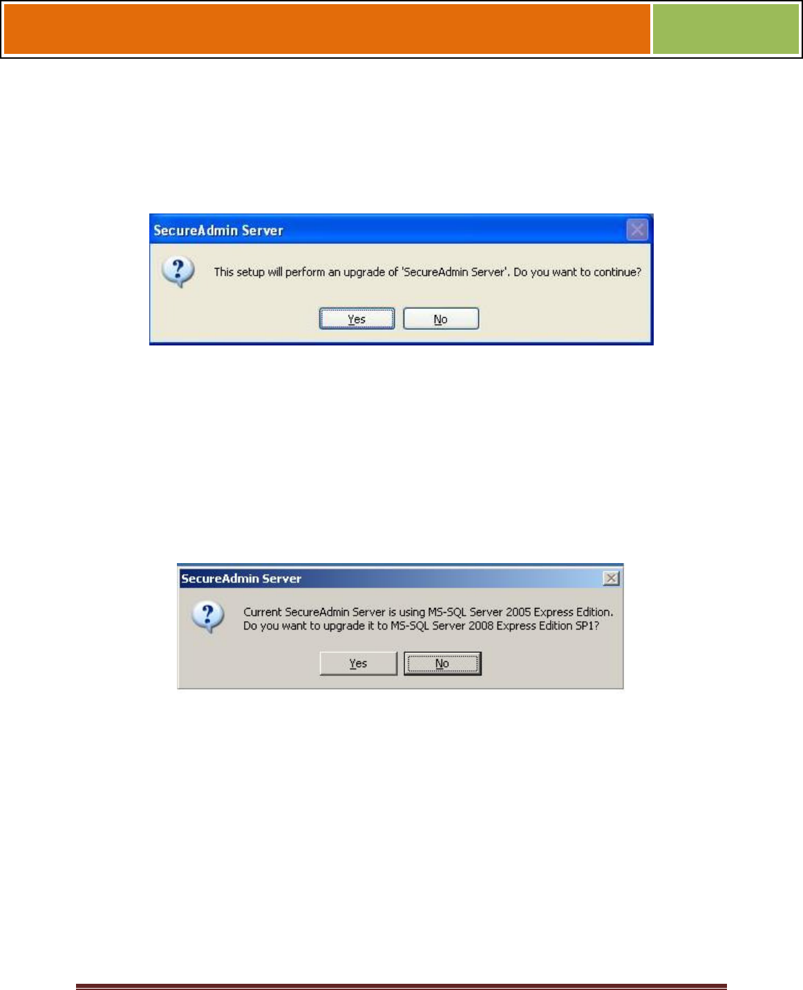
1. When you run the setup of SecureAdmin server, it checks to see if previous version
of SecureAdmin server is already installed on the machine. If yes, it prompts to
upgrade SecureAdmin server. Click Yes to continue with upgrade install.
Figure 3-10 Upgrade Confirmation
If you have installed previous version of SecureAdmin server with SQL Server 2005,
installer prompts to upgrade from SQL Server 2005 to SQL Server 2008. Click Yes if
you intend to migrate to SQL Server 2008.
Clicking Yes will install SQL Server 2008 locally if it is not installed. It will upgrade
existing SQL Server 2005 database catalog and migrate it to SQL Server 2008.
Clicking No will upgrade existing SQL Server 2005 database catalog.
Figure 3-11 Upgrade from MS-SQL Server 2005 Express Edition Confirmation
Click Finish. This completes the SecureAdmin server installation and exits the installer
Figure 3-12 SecureAdmin Server Installation Complete
October 15 2009 – Installation Guide Draft – Edit Purposes Only Page 41
Installation Guide –April 2010
2010
3.1.2 SECUREADMIN CLIENT
To install the SecureAdmin client software, follow these steps:
1. Insert the CD into the optical drive. If Autoplay is enabled, the installation process
will start automatically. A menu is displayed. If Autoplay is not enabled, start the
installation process manually by doubleclicking the Setup.exe file located in the
SecureAdmin folder on the CD.
Figure 3-13 Menu
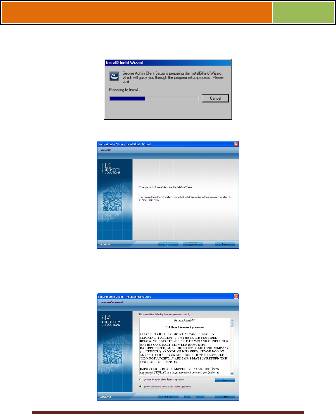
Click Client Installation. The InstallShield Wizard is started and the target system is
examined. The Welcome screen is displayed.
October 15 2009 – Installation Guide Draft – Edit Purposes Only Page 42
Installation Guide –April 2010
2010
Figure 3-14 InstallShield Wizard
Figure 3-15 Welcome Screen
Click the Next button to continue. The License Agreement screen is displayed.
Figure 3-16 SecureAdmin Client License Agreement
October 15 2009 – Installation Guide Draft – Edit Purposes Only Page 43
Installation Guide –April 2010
2010
The L-1 Identity Solutions License Agreement is displayed. Select the appropriate radio
button to agree with the terms and then click the Next button. The Choose
Destination Location screen is displayed.
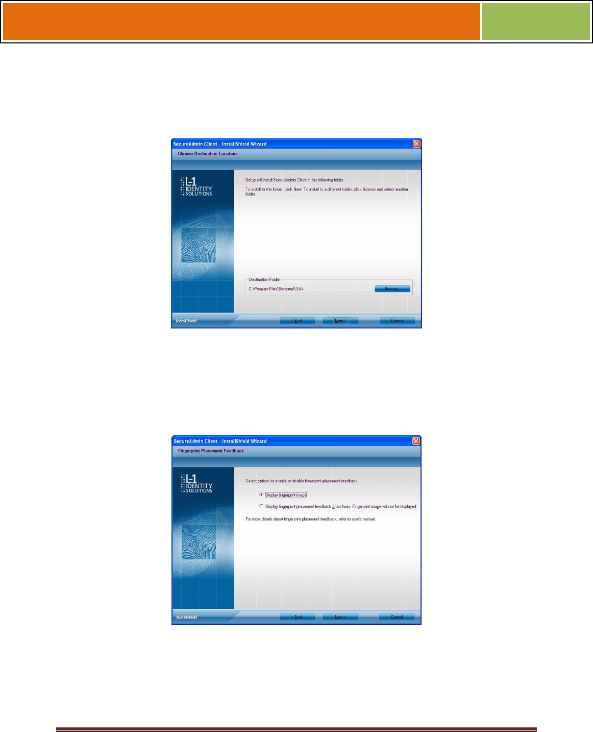
Figure 3-17 SecureAdmin Client Choose Destination Location
Accept the default installation folder and click the Next button or click Browse to choose
your own installation path. After you specify a destination folder, the Fingerprint
Selection Feedback selection screen is displayed.
Figure 3-18 Fingerprint Placement Feedback Option Selection
Select the appropriate radio button to either display or to not display fingerprint data. If
Display Fingerprint Image is selected, a fingerprint will be displayed while
enrolling templates. If the Display Fingerprint Placement Feedback option is
selected, then SecureAdmin displays crosshair placement feedback instead of
fingerprint images while enrolling templates.
October 15 2009 – Installation Guide Draft – Edit Purposes Only Page 44
Installation Guide –April 2010
2010
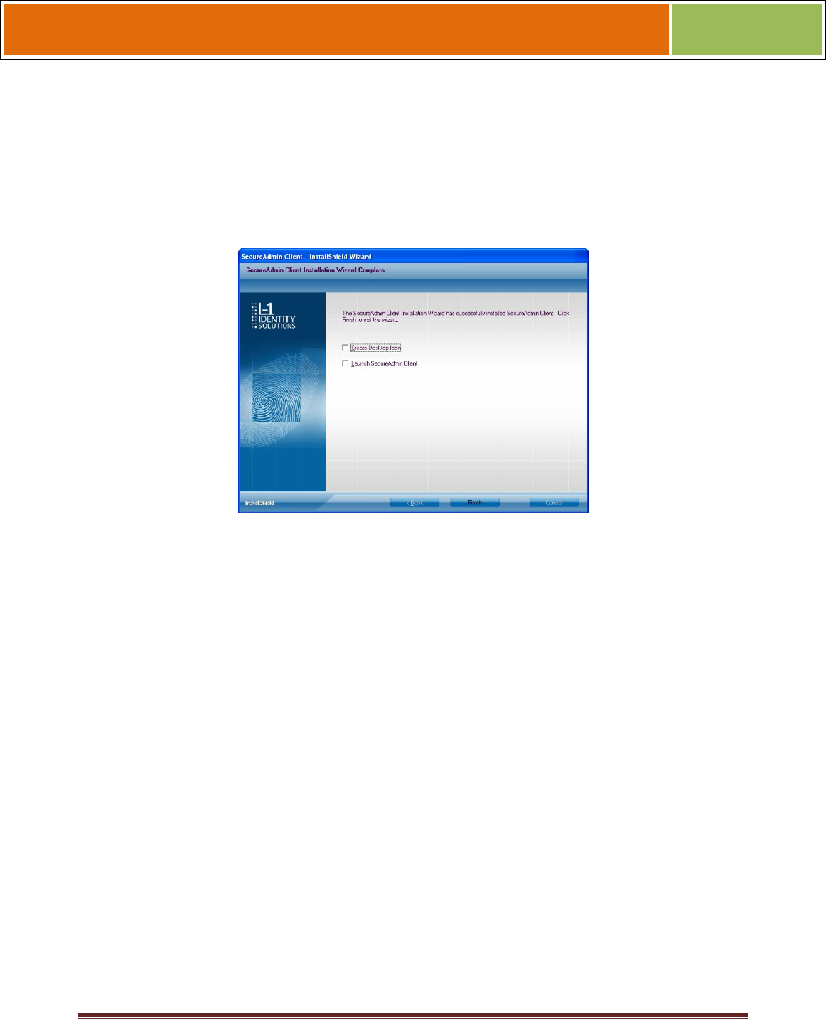
Click the Next button. The InstallShield Wizard completes the installation and displays a
Finished screen.
Select either or both of the optional Check Create Desktop Icon and Launch Secure
Admin Client check boxes.
Figure 3-19 InstallShield Wizard Finished
Click the Finish button.
3.1.2.1 MODIFYING AN INSTALLATION OF SECUREADMIN CLIENT
To modify an installation:
1. Login as Administrator and go to the Secure Admin installer.
Double-click the Setup.exe installer file to start the installer.
On the L1 Identity Solutions screen, select the Client Installation option.
On the Secure Admin Welcome screen, select the Modify option. Click Next to
continue.
Select the appropriate Fingerprint Placement Feedback option. If Display
Fingerprint Image is selected, fingerprints will be displayed while enrolling
templates. If Display Fingerprint Placement Feedback is selected, SecureAdmin
displays crosshair feedback instead of fingerprint images while enrolling templates.
Click Next to continue.
On the Maintenance Complete screen, click the Finish button to complete the
modified installation.
3.1.2.2 REPAIRING AN INSTALLATION OF SECUREADMIN CLIENT
To repair an installation:
1. Login as Administrator and go to the Secure Admin installer.

October 15 2009 – Installation Guide Draft – Edit Purposes Only Page 45
Installation Guide –April 2010
2010
Double-click the Setup.exe installer file to start the installer.
On the L1 Identity Solutions screen, select the Client Installation option.
On the SecureAdmin Welcome screen, select the Repair option. Click Next to continue.
On the Maintenance Complete screen, click the Finish button to complete the repair
installation process.
3.1.2.3 UNINSTALLING SECUREADMIN CLIENT
Uninstall SecureAdmin Client by using either the Add/Remove Program function in
Windows or by using the Remove option from the installation file.
To uninstall SecureAdmin client by using the Remove option within the installation file,
follow the instructions for repairing an installation. Select the Remove option instead of
the Repair option, then follow the prompts.
3.1.2.4 UPGRADING AN INSTALLATION OF SECUREADMIN CLIENT
To upgrade a previous version of SecureAdmin Client, first uninstall the older version
using Windows Add/Remove Programs or the SecureAdmin installer, then re-install the
new version of SecureAdmin Client.