Bioscrypt VPROXAH4065 V-Prox, A User Manual VeriSeries UserManual
Bioscrypt, Inc. V-Prox, A VeriSeries UserManual
UserManual.wiki
>
Bioscrypt
>
VPROXAH4065 User Manual
>
users manual 1
Contents
1.
users manual 1
2.
users manual 2
users manual 1
Navigation menu
Upload a User Manual
Namespaces
Wiki Guide
HTML
PDF
Info
Views
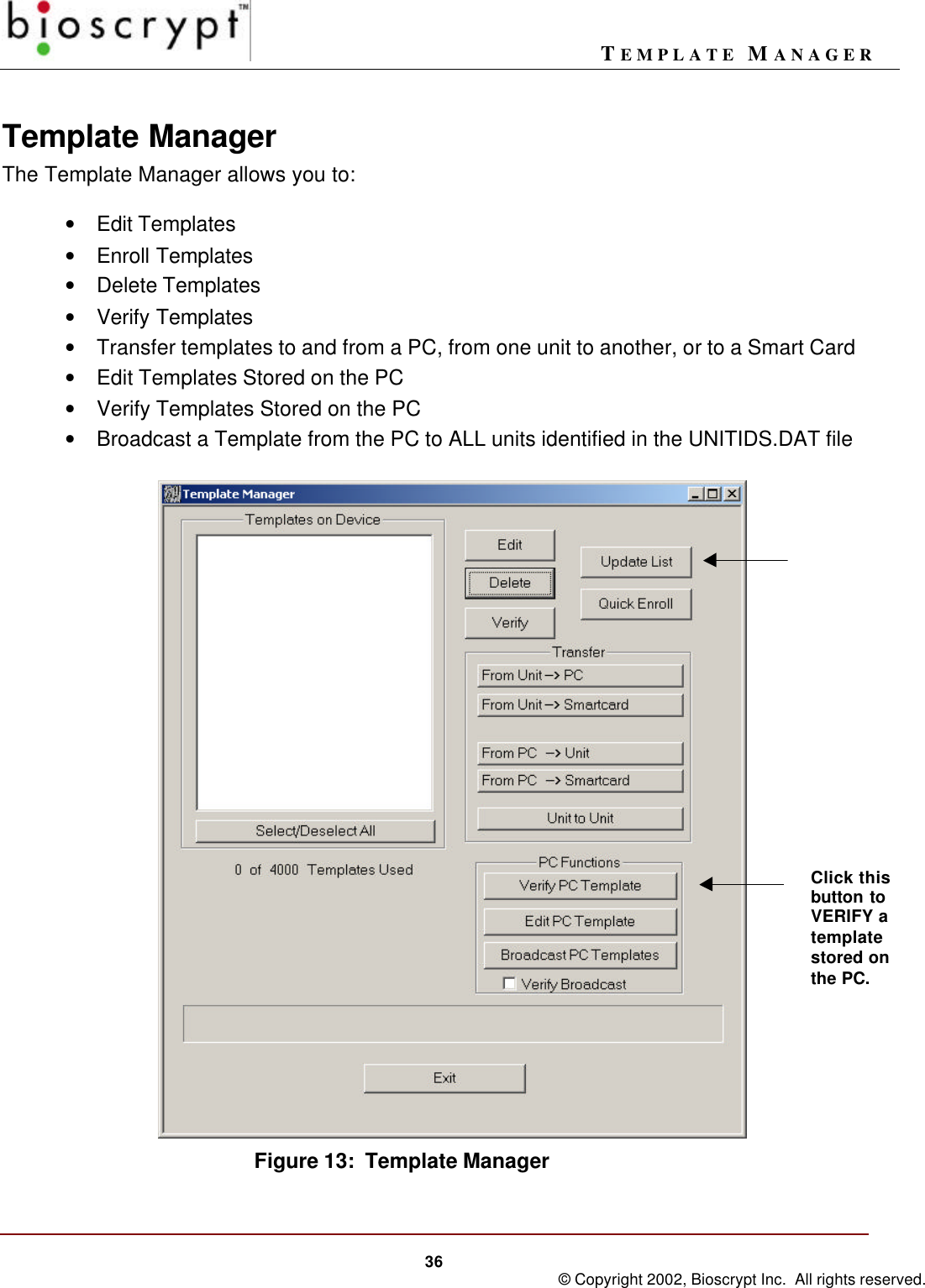
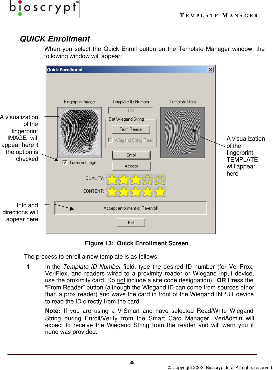
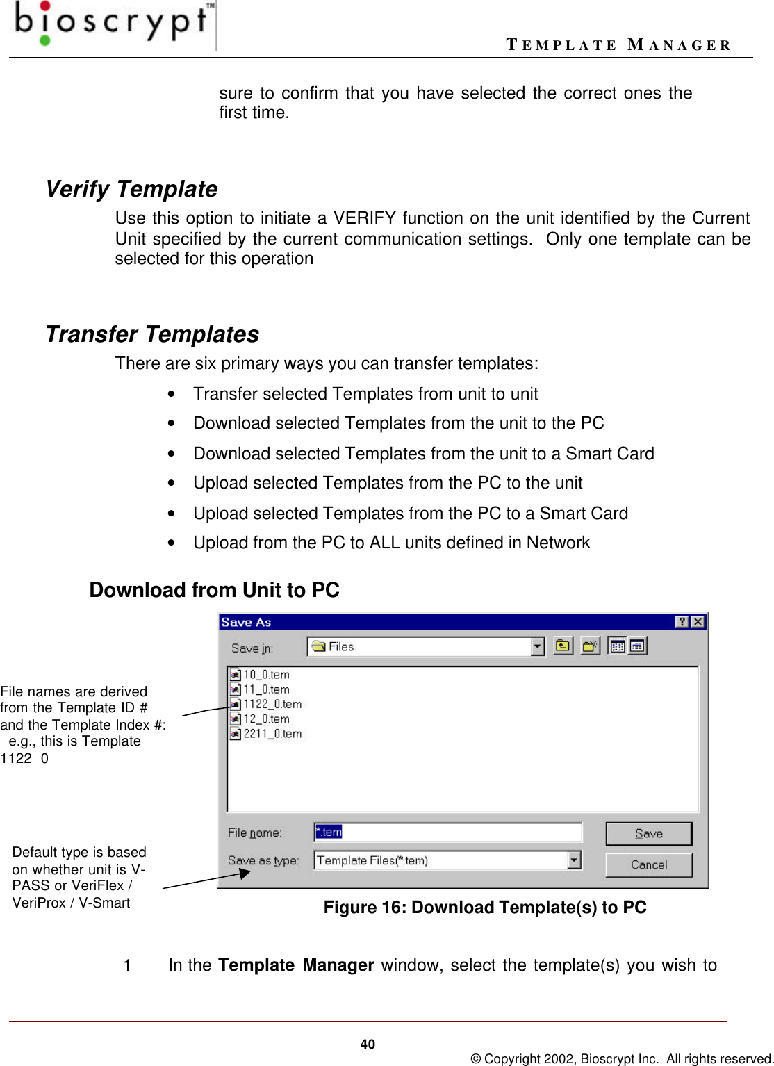
User Manual
Discussion / Help
Navigation