Bioscrypt VPROXAH4065 V-Prox, A User Manual VeriSeries UserManual
Bioscrypt, Inc. V-Prox, A VeriSeries UserManual
UserManual.wiki
>
Bioscrypt
>
VPROXAH4065 User Manual
>
users manual 2
Contents
1.
users manual 1
2.
users manual 2
users manual 2
Navigation menu
Upload a User Manual
Namespaces
Wiki Guide
HTML
PDF
Info
Views
User Manual
Discussion / Help
Navigation


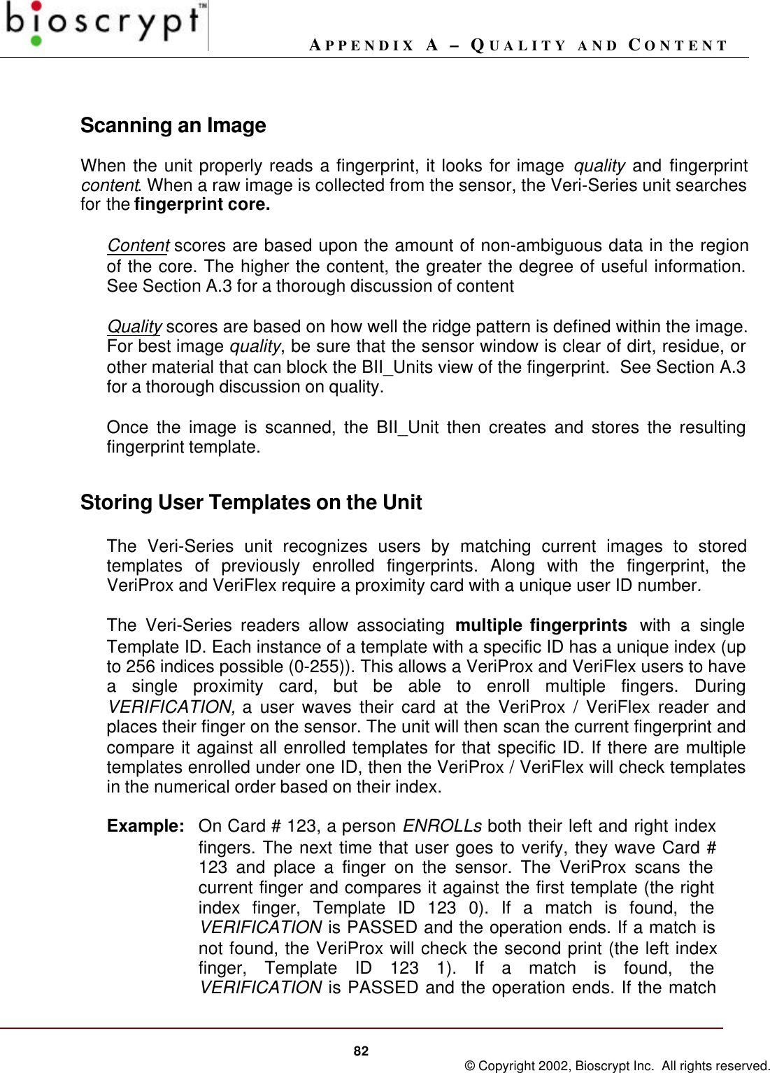
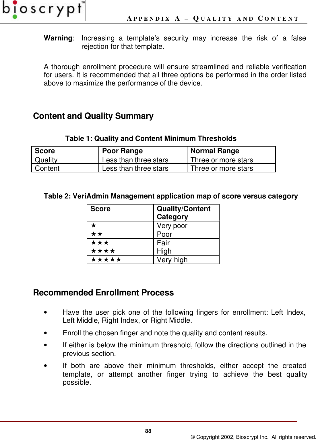
![APPENDIX A – QUALITY AND CONTENT86 © Copyright 2002, Bioscrypt Inc. All rights reserved.QualityThe quality score is based on how well the ridge pattern is defined within thefingerprint image that was enrolled. In other words, quality measures how clearlythe unit imaged the fingerprint. Poor quality enrollments can result in an elevatedrate of false rejection making it difficult for the user to verify reliably.The score is given in stars («) and ranges from zero to five stars, with five beingthe best quality (rarely obtained) and zero being the worst. Quality scores of threestars and higher perform well with the Bioscrypt verification algorithm. In thisrange, the algorithm readily compensates for differences in fingerprint quality. Itstatistically is still true that the larger the quality score the better the performanceof an enrollment.As a general rule of thumb, quality scores less than three stars require interventionon the part of the Enroller or administrative software. Sources of low scoresinclude dry fingers and dirty sensors.If the quality score falls below three stars, Bioscrypt recommends the followingoptions:• Ensure that the sensor and finger are clean.• If the finger and sensor are clean and a dry finger is suspected, try re-enrollingone more time, leaving the finger on the sensor for several seconds prior toenrollment. Frequently finger moisture accumulates over time to provide agood image.• Fingerprint quality can vary among individual fingers for the same person. Tryenrolling an alternate finger to see if the score improves.• Alter the security level for that particular template by decreasing the threshold aminimum of 1 level (e.g., change the value from medium [3] to low [4]). This willoffset the false rejection for that template by making it easier to match. If use ofthat template indicates that raising the threshold one level still produces falserejections, try setting the value to its lowest security (level 5).Warning:Decreasing a template’s security may increase the risk of afalse acceptance for that template.Very LowQualityVery Highquality](https://usermanual.wiki/Bioscrypt/VPROXAH4065.users-manual-2/User-Guide-246647-Page-29.png)
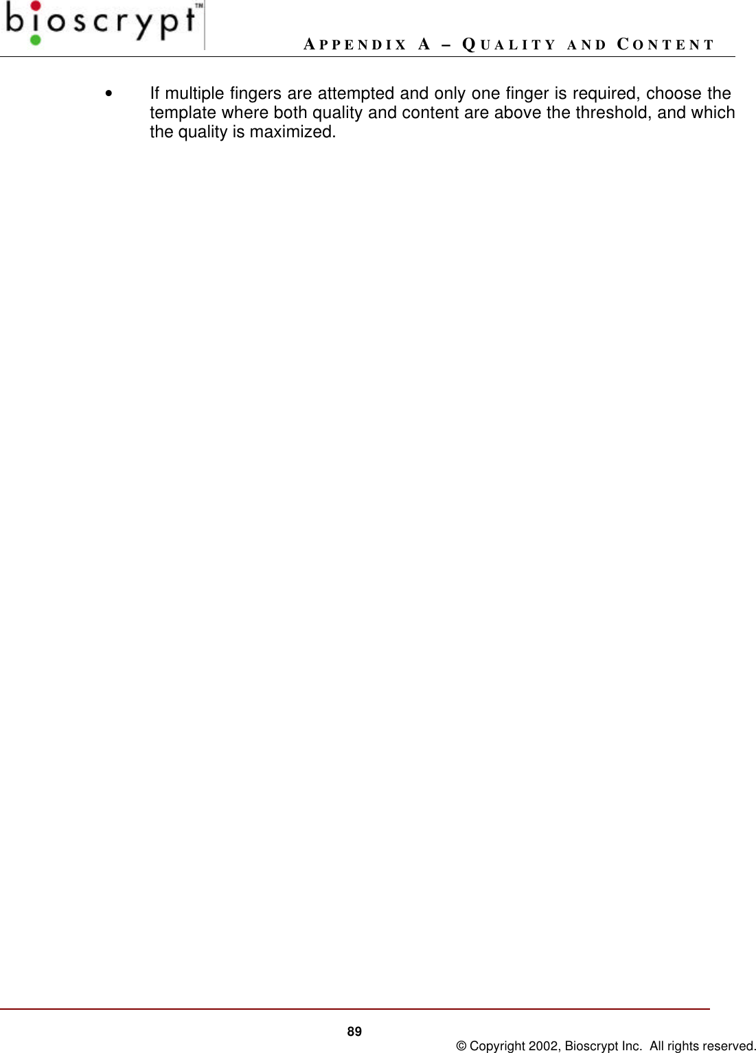
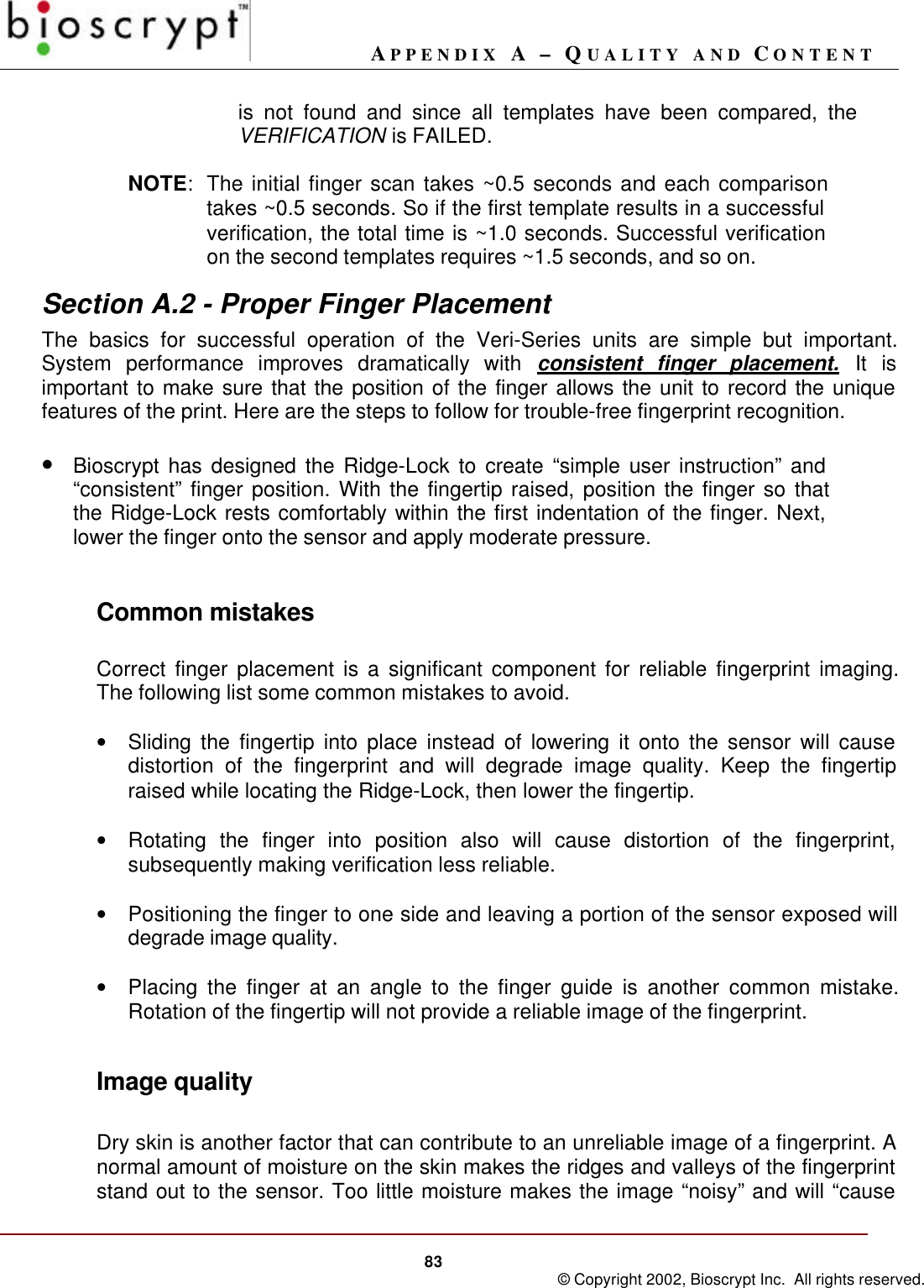
![APPENDIX A – QUALITY AND CONTENT87 © Copyright 2002, Bioscrypt Inc. All rights reserved.A thorough enrollment procedure will ensure streamlined and reliable verificationfor users. It is recommended that all four options be performed in the order listedabove to maximize the performance of the device.ContentThe Content score is based upon the amount of usable information the Veri-Seriesunit sees in the fingerprint. Templates that are characterized by low content scoresmay result in elevated rates of false acceptance.Again, the score is given in stars («) and ranges from zero to five stars, with fivebeing the most content and zero being the least. Content scores of three stars andhigher perform well with the Bioscrypt Algorithm. In this range the algorithm hasenough information to distinguish between different fingerprints with a high level ofaccuracy. Templates with content scores above two stars do not vary in terms ofthe error rates.Content scores less than three stars require intervention on the part of the Enrolleror administrative software. Sources of poor content include improper fingerpositioning and extremely bland fingerprints.If the content score falls below three stars, Bioscrypt recommends the followingoptions:• Try re-enrolling the same finger if finger positioning seems to be the issue(see section A.2). Ensure that the user can comfortably place the finger onthe sensor while maintaining the core region in the image.• Fingerprint content can vary among individual fingers for the same person.Try enrolling an alternate finger to see if the score improves.• Alter the security level for that particular template by increasing thethreshold a minimum of 1 level (e.g., change the value from medium [3] tohigh [2]). This will offset the false acceptance for that template by making itmore difficult to match. If use of that template indicates that raising thethreshold one level still produces false rejections, try setting the value to itshighest security (level 1).Very HighContentLow Content](https://usermanual.wiki/Bioscrypt/VPROXAH4065.users-manual-2/User-Guide-246647-Page-30.png)