Bioscrypt VPROXAH4065 V-Prox, A User Manual VeriSeries UserManual
Bioscrypt, Inc. V-Prox, A VeriSeries UserManual
Contents
- 1. users manual 1
- 2. users manual 2
users manual 2

UNIT PARAMETER SETTINGS
58 © Copyright 2002, Bioscrypt Inc. All rights reserved.
Creating USER DEFINED PASS-THRU Format Options
The user has the ability to add custom defined PASS-THRU formats to the
VeriAdmin software. These will be added to the dropdown list in the BII_UNIT
PARAMETER SETTINGS dialog box. In the installation directory there is a file
called WFORMAT.DAT that contains all displayed Wiegand formats.
WFORMAT.DAT contains both pre-defined formats and PASS-THRU
formats. See below for and example contents of that file. All lines that begin with
‘//’ are ignored. PRE-DEFINED formats follow the format:
WIEGAND <MV1100_Code> <#bits> <text_string(no spaces)>
WARNING: These should NOT be changed or added to unless directed by Bioscrypt
TECHNICAL SUPPORT. Any modifications to this section could cause unreliable
Wiegand communications using PRE-DEFINED formats.
The next section shows the PASS-THRU Formats and follows the format:
WIEGAND_PASS <label> <TOTAL_BITS> <ID_START_BIT> <ID_NUM_BITS>
Where:WIEGAND_PASS is the identification that this is a PASS_THRU format
<label> is the Description shown in the dropdown list (no spaces)
<TOTAL_BITs> is the total number of bits in the entire Wiegand String (maximum is 64)
<ID_START_BIT> is the starting bit of the ID FIELD(where the first bit is 0)
<ID_NUM_BITS> is number of bits in the ID FIELD (must be contiguous)

UNIT PARAMETER SETTINGS
59 © Copyright 2002, Bioscrypt Inc. All rights reserved.
For Example:
Standard 26-bit Wiegand is -- PSSSSSSSSDDDDDDDDDDDDDDDDP
(1 Parity bit, 8 SITE CODE bits, 16 ID bits, 1 Parity)
- 26 total bits
- ID Start Bit is 9 - (where first bit is 0)
- ID Number of Bits is 16
This would be represented as:
WIEGAND_PASS 26-Bit-Pass_Thru 26 9 16
And the text, “26-Bit-Pass_Thru” would be added to the dropdown box. Selection of this option
would show the data in the associated boxes.
As seen below, one special format ( CUSTOM –1 –1 –1 ) is also added. When this is selected,
the user can enter the TOTAL_BITS, ID_START_BITS, and ID_NUM_BITS directly into the
VeriAdmin user interface. These values can then be sent to the BII_UNIT. The values are NOT
saved to the WFORMAT.DAT file however. To add items directly to the file, any standard text
editor will work since WFORMAT.DAT is a text file.
//
// format is: IDENTIFIER MV1100_Code #bits text_string(no spaces)
//
WIEGAND 0 26 Standard
WIEGAND 1 44 Apollo
WIEGAND 2 34 Northern
WIEGAND 3 34 Northern(no_parity)
WIEGAND 4 34 Ademco
WIEGAND 5 35 HID_Corporate
WIEGAND 6 37 HID
//
// format is: IDENTIFIER text_string(no spaces) TOTAL_BITS ID_START_BIT ID_NUM_BITS
// (* note: ID_START_BIT is zero-based *)
//
WIEGAND_PASS 26-Bit-Pass_Thru 26 9 16
WIEGAND_PASS Kantech-XSF 39 22 16
WIEGAND_PASS CUSTOM -1 -1 –1

UNIT PARAMETER SETTINGS
60 © Copyright 2002, Bioscrypt Inc. All rights reserved.
AUX PORT SECURITY
This allows the Administrator to set a password for the AUX port to DISABLE
unauthorized AUX Port communications. The purpose is to prevent unauthorized users
from accessing the AUX port unless the password is supplied to re-ENABLE the port.
In the dialog, the current state is shown. The Administrator would select DISABLE
and supply a numeric password, and press the SET button. The supplied numeric
password should be remembered since it is required to ENABLE the AUX port while
communicating on the AUX port.
Once the AUX port is disabled, no communications are accepted over the AUX
port unless ENABLE PORT option is chosen in 1 of 2 ways.
• If communicating over the HOST PORT
o the ENABLE PORT command will enable AUX port communications and a
password is NOT required. This allows the unit to be reset over the HOST port
if the AUX password is forgotten. VeriAdmin allows this since the network is
considered secure.
• If communicating over the AUX PORT
o The ENABLE PORT command will enable AUX port communications ONLY if
the correct password is supplied. All other commands will return an error
indicated a ‘locked port’ until the port is enabled properly
Bioscrypt recommends that the AUX port be disabled and password
protected
When an Administrator needs to communicate with the device using the AUX Port,
the procedure would be:
• connect to the AUX port,
• use VeriAdmin to bring up the BII_UNIT PARAMETER SETTINGS dialog
• choose ENABLE PORT, supply the correct password, and press SET
All communications would then be allowed. Once all data is gathered, the Administrator
would then disable the AUX port by:
• use VeriAdmin to bring up the BII_UNIT PARAMETER SETTINGS dialog
• choose DISABLE PORT, supply a new password, and press SET
This would once again protect the AUX port from unauthorized use.
BROADCAST PARAMETERS
61 © Copyright 2002, Bioscrypt Inc. All rights reserved.
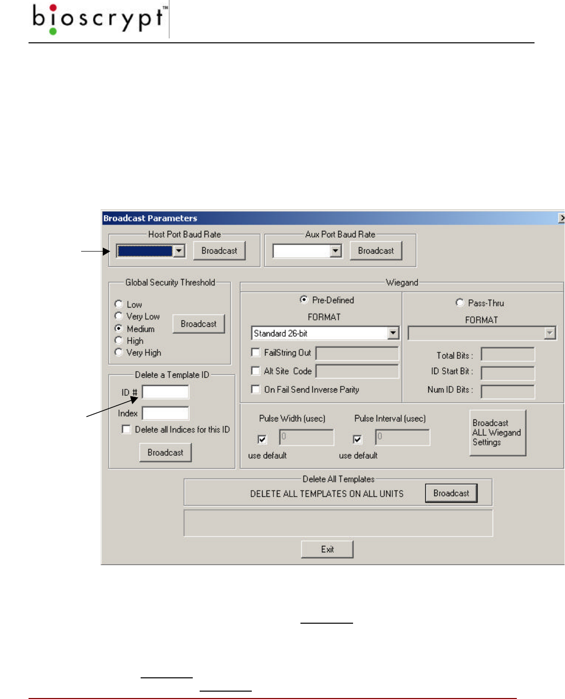
Broadcast Parameters
The Broadcast window allows you to modify settings on all units in a networked
environment at the same time (See Appendix B). Under most circumstances, you
will use this window when communicating over the Host Port (recall that the Aux
Port primarily is for communicating with a single unit). You will note that the
window is similar to the Unit Parameters window.
Figure 21: Broadcast Parameters Window
Note: As with the BII_Unit Parameter Settings window, change one
setting at a time and click the Broadcast button after each change.
For example: if you wish to change the Security Threshold and the
Wiegand Out string: 1) change the threshold; 2) click the
Broadcast button in the security section; 3) change the string; and,
4) click the Broadcast button in that section.
The PC baud
rate will update
automatically.
Enter the ID#,
then either:
enter the
Index#, or check
the Delete all
indices… box
NETWORK STATUS
62 © Copyright 2002, Bioscrypt Inc. All rights reserved.
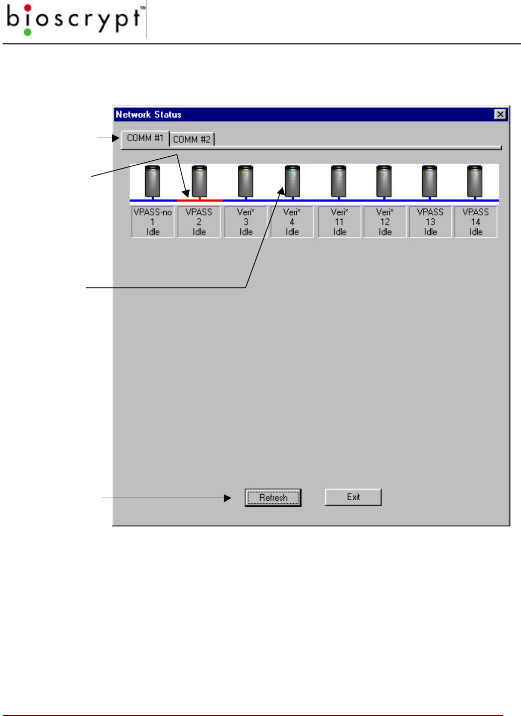
Network Status
The Net Status window displays the condition of all units networked.
Figure 226: Network Status Window
Each unit defined in the UNITIDS.DAT file is represented with a TAB for each defined
Communications Port. 3 lines of text identify:
• The Type of unit (Veri*, V-PASS or V-PASS-no) as defined in UNITIDS.DAT file
• The Network ID
• State (Idle, Busy, No Response)
Comm Port TAB
Pressing
REFRESH will
check all units
on the selected
COMM Port
RED represents
the currently
selected unit
You can click
the mouse
button on each
Icon to make
that UNIT the
currently
selected unit

NETWORK STATUS
63 © Copyright 2002, Bioscrypt Inc. All rights reserved.
The Veri* designates a unit is a VeriProx or VeriFlex. V-PASS designates a V-PASS product
and “V-PASS-no” represents a V-PASS product with Auto Finger Detect turned OFF. A type of
‘MISMATCH’ indicates the UNITIDS.DAT file does not match the actual unit on the network.
ADVANCED ENROLLMENT
64 © Copyright 2002, Bioscrypt Inc. All rights reserved.
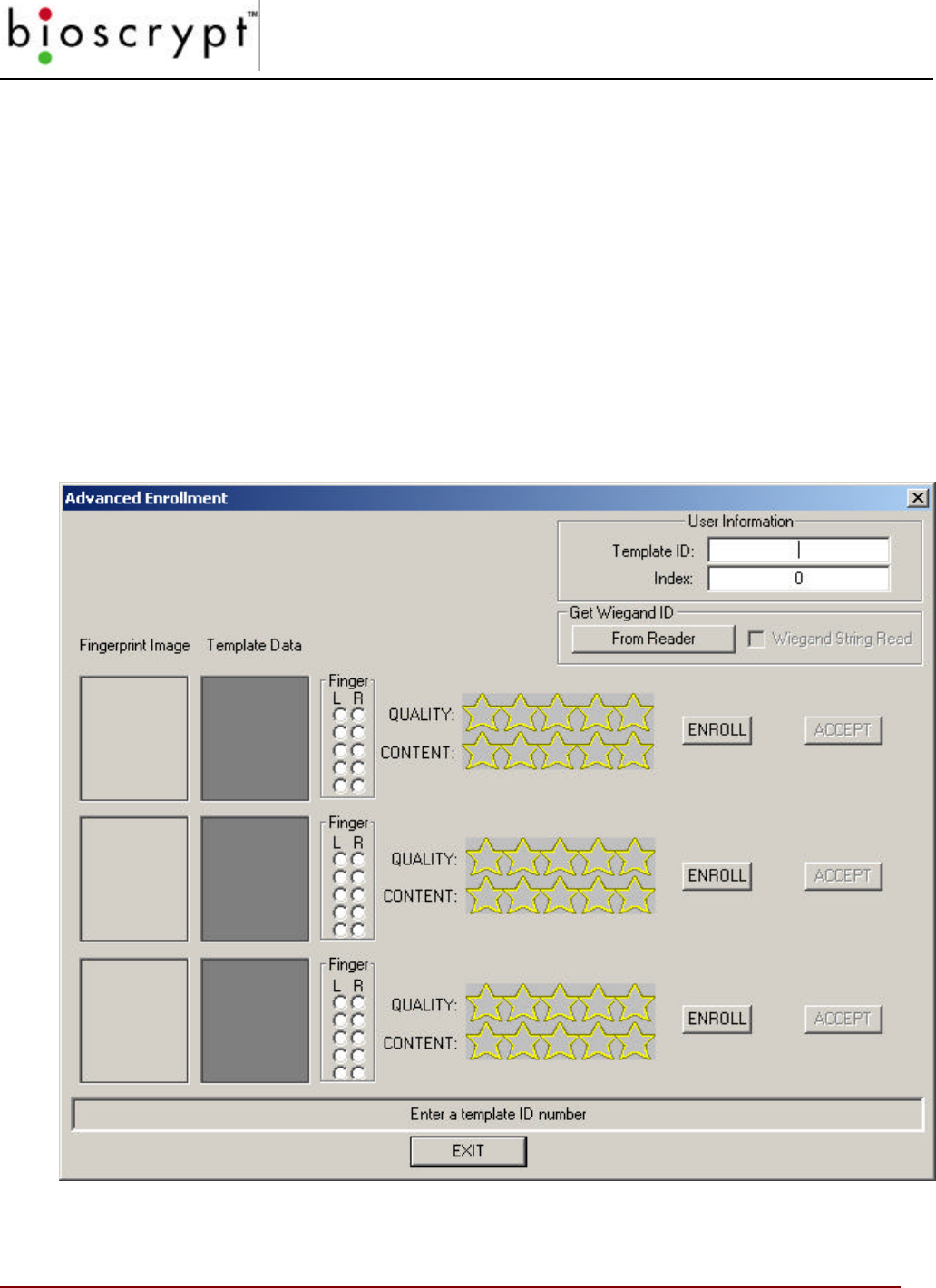
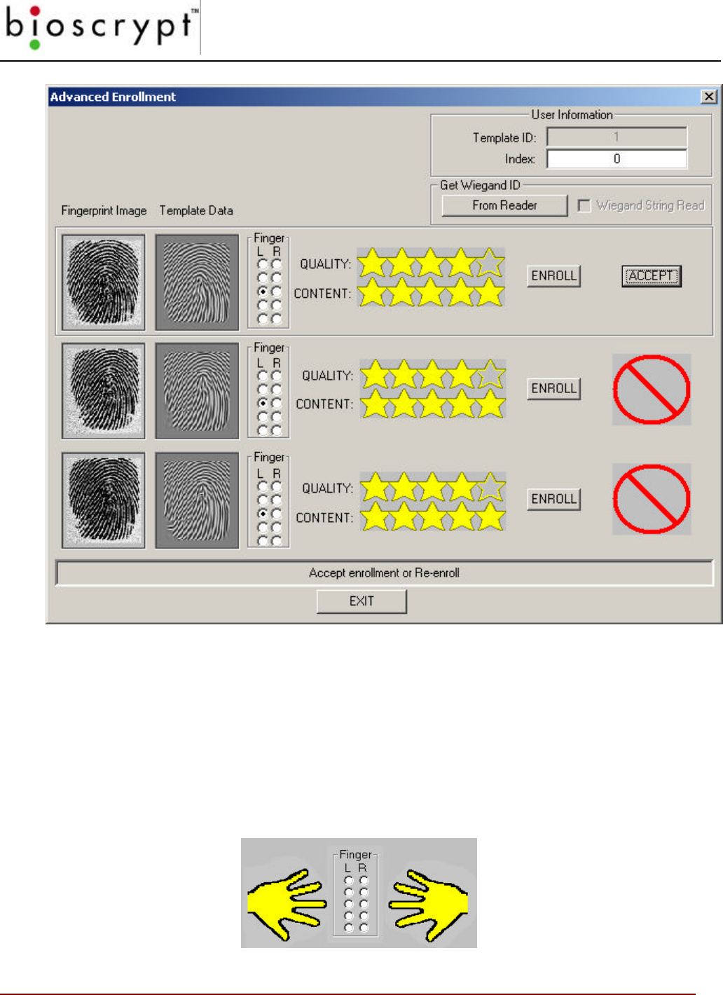
Advanced Enrollment
The Advanced Template Enrollment is the recommended tool for enrolling all
templates. This allows multiple templates to be sampled and the corresponding
template created. Users can sample different finger or multiple enrollments of the
same finger. Each time an enrollment is sampled, the “best” template is identified
between the current 3 samples. Users then have the option of ACCEPTing the
enrollment of their choice. NOTE: No enrollments are saved until 1 of the 3
ACCEPT buttons is pressed.
This tool can be used to train users by demonstrating how proper finger placement
is a critical aspect in obtaining a good enrollment. This tool can also show how
different fingers on the same person can have very different QUALITY and
CONTENT ratings.
Figure 27: The Advanced Enrollment Screen

ADVANCED ENROLLMENT
65 © Copyright 2002, Bioscrypt Inc. All rights reserved.
The Advanced Enrollment process is as follows:
1. In the Template ID field, type in the Template ID (the template ID should be the
proximity card ID number for the VeriProx or if a Wiegand IN device is used. Do not
include a site code designation.) OR Press the FROM READER button and wave the
card in front of the Wiegand INPUT device to read the ID from the card.
2. In the Index field, enter the index of the template.
3. Click any ENROLL button.

ADVANCED ENROLLMENT
66 © Copyright 2002, Bioscrypt Inc. All rights reserved.
ADVANCED ENROLLMENT
67 © Copyright 2002, Bioscrypt Inc. All rights reserved.
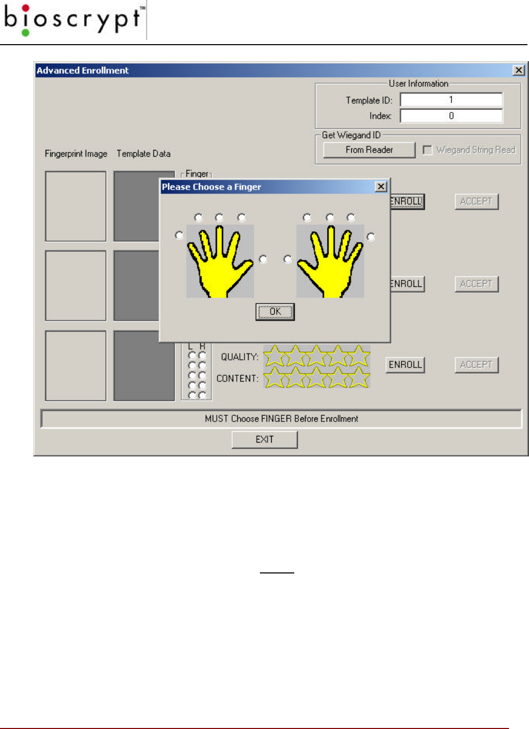
Figure 28: Advanced Enrollment – Finger Selection
4. A pop-up dialog box will allow the User to choose the finger to ENROLL. Choose
which finger by clicking the corresponding checkbox.
5. The light on the current unit will glow amber requesting the enrollee to place a finger
on the sensor. Nestle the Ridgelock into the first joint line on the finger. An image is
scanned and both the image and corresponding template are displayed. The finger
may be removed when the amber light goes out.
6. The Advance Enrollment tool will then choose the best template among the 3 and
indicate which Enrollment should be ACCEPTed.

ADVANCED ENROLLMENT
68 © Copyright 2002, Bioscrypt Inc. All rights reserved.
ADVANCED ENROLLMENT
69 © Copyright 2002, Bioscrypt Inc. All rights reserved.
Figure 29: Advanced Enrollment – Recommended Choice
7. Repeat Steps 3-6 to Enroll additional sample templates. A current template can be
replaced by choosing the finger to be Enrolled and pressing the ENROLL button.
NOTE: Users can indicate which finger by selecting the corresponding checkbox in the
FINGER sub-window. The checkboxes represent the fingers as if both hands where
placed flat on the display with fingertips touching as shown in Figure 26.
ADVANCED ENROLLMENT
70 © Copyright 2002, Bioscrypt Inc. All rights reserved.
Figure 30: Advanced Enrollment – Finger Selection Option
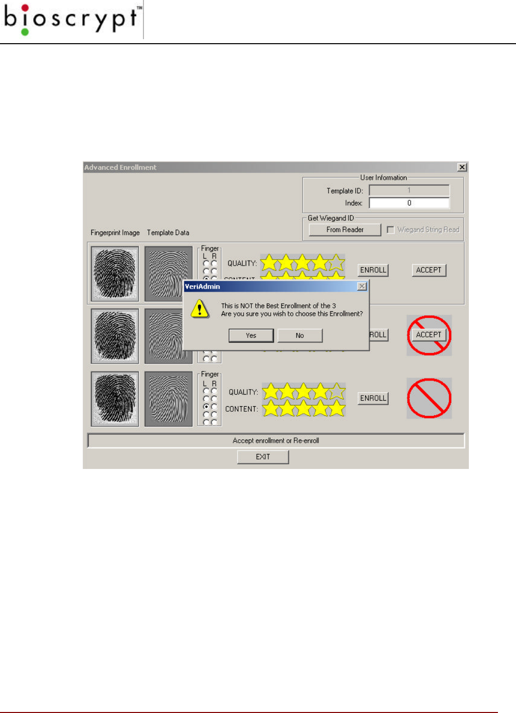
8. Although NOT recommended by Bioscrypt, users have the option of choosing a
different Enrollment other then the one recommended. Simply press the ACCEPT
button even though it is hidden by the red “NO” symbol. A warning message will be
displayed to confirm this un-recommended action is desired.
Figure 31: Advanced Enrollment – OVERRIDE Recommended Choice
9. Once an Enrollment has been selected, the normal EDIT TEMPLATE window appears
so that fields can be verified and additional data added. Here is where the User Type
and Security Threshold can be set. See the section is this manual on EDIT
TEMPLATES for more details on saving the template to either the current unit or the
PC disk.
LED TABLE SETTINGS
71 © Copyright 2002, Bioscrypt Inc. All rights reserved.
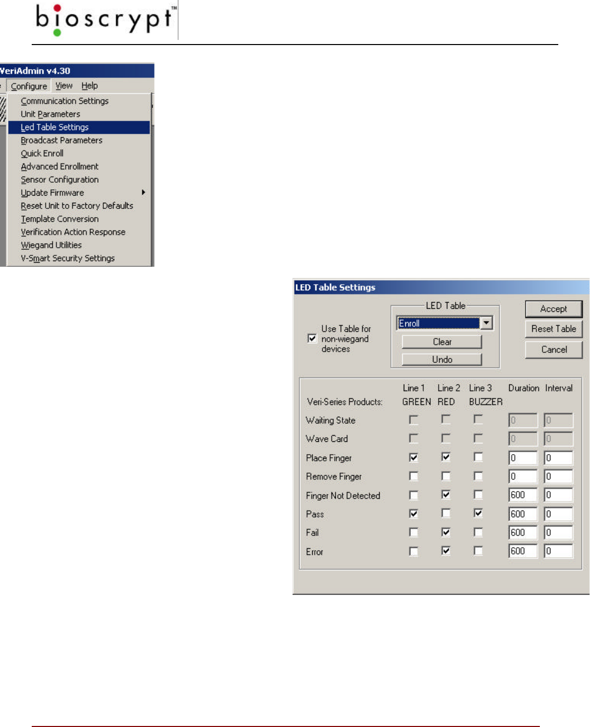
Figure 32: LED Table Settings
LED Table Settings
Choosing the LED Table Settings menu item will allow the user to define
how the reader’s LED will function under specific operations. Selecting
this option will display the dialog shown in figure 30. The dropdown
selection box chooses the function (enroll, verify, idle, etc.) to modify.
Below that is each possible state for the selected operation. Line 1
represents GREEN LED, Line 2 represents RED LED, and Line 3
represents the Buzzer.
In the example shown, the ENROLL
function is chosen. The first two states are
disabled since they have no meaning
for the ENROLL function.
Both Line 1 and Line 2 are chosen to
indicate PLACE FINGER. This will turn
GREEN and RED LEDs on creating a
YELLOW LED.
The REMOVE FINGER operation is
signaled by clearing all LEDs, thus
making the LED turn off.
If a FINGER NOT DETECTED
happens, then the RED LED is shown
for 600 milliseconds.
A PASS is indicated by both turning the
LED GREEN and sounding the
BUZZER for 600 milliseconds.
To indicate a FLASHING LED, choose
the duration and set the INTERVAL
time (1350 is normal).
Figure 33: LED Table Settings
The USE TABLE checkbox indicates whether to use these setting for non-Wiegand
initiated commands (like commands coming from PC). Repeat process of other functions
then press the ACCEPT to transfer to the current unit. If the ACCEPT is not pressed, the
changes are ignored.
SENSOR CONFIGURATION
72 © Copyright 2002, Bioscrypt Inc. All rights reserved.
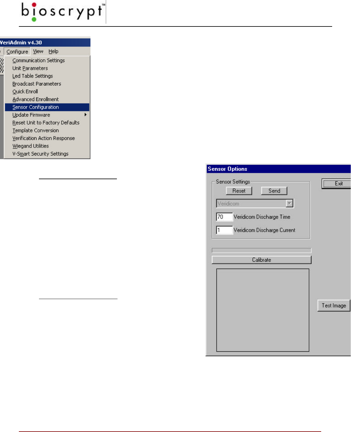
Sensor Configuration
Note: This feature has been disabled in recent versions of
VeriAdmin, including v4.3
Choosing the Sensor Configuration menu item will allow the reader’s
sensor settings to be altered. It is recommended that only advanced
users attempt to modify these settings since they can drastically affect
the fingerprint reader’s performance. Please call Bioscrypt Technical
Support with any questions before attempting modifications.
The Bioscrypt sensor needs to be
calibrated for optimal performance.
For Veridicom Sensors:
To perform this task the user should place their
finger on the sensor of the reader identified by
the current Communication settings. Next, press
the CALIBRATE button and hold the finger
steady until the progress bar completes. The
new values will be displayed and the VeriAdmin
software will ask if you want to see a test image.
With the finger still on the sensor, select YES. An
image will be scanned and displayed. If the
image looks good, choose YES to accept the new
values.
For Authentec Sensors:
To perform this task the user should NOT place
their finger on the sensor of the reader. Press the
CALIBRATE button.
The TEST IMAGE button will scan and display
a fingerprint image.
Figure 34: Sensor Configuration Menu
Figure 35: Sensor Configuration
NOTE: A Network ID of –1 is
NOT valid for these operations
UPDATE FIRMWARE
73 © Copyright 2002, Bioscrypt Inc. All rights reserved.
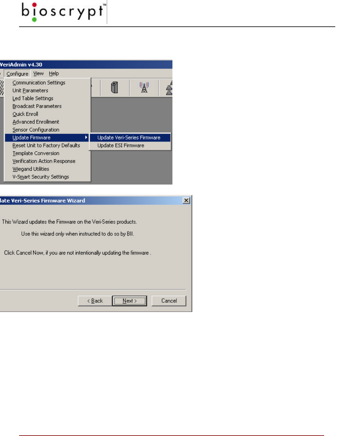
Figure 37: Update Firmware Menu Option
Update Firmware
Choosing the Update Firmware menu item will
allow the reader’s DSP firmware to be field-
updated. Also, for V-Smart units, the external
storage device (ESI) can also be programmed
in the field. It is recommended that only
advanced users attempt to perform this
operation. Please call Bioscrypt Technical
Support with any questions.
Figure 36: Update Firmware Menu
Option
Choosing this option will begin the
Update Firmware Wizard. Follow the
steps and choose the correct firmware
file. This process can take between 1-10
minutes depending on the current baud
rate settings.
NOTE: Before attempting this operation,
make sure the current communication
settings are correct and that the PC and
reader are communicating properly. It is
recommended that the HELP, ABOUT VERIADMIN menu option is used both before and after
this operation to ensure the firmware version changed. Depending on the prior version,
downloading a new firmware version may also cause an extra step to be performed after the
firmware download. If this happens, the user will be given informational messages indicating
the additional steps. Although not necessary, it is recommended that all templates be backed-
up to the PC before a firmware update. If power is disconnected during a firmware update, the
Bioscrypt unit may become inoperable.
Figure 34: Update Firmware
Wizard
RESTORE FACTORY DEFAULTS
74 © Copyright 2002, Bioscrypt Inc. All rights reserved.
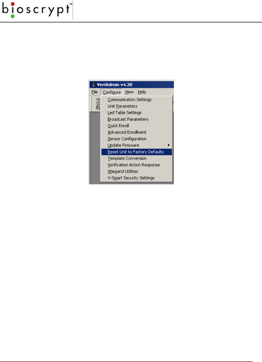
Restore Factory Defaults
Choosing the Restore Factory Defaults menu item will allow the Bioscrypt reader to be
reset to the default firmware setting. It is recommended that only advanced users attempt
to use this operation. Please call Bioscrypt Technical Support with any questions.
Figure 38: Reset BII_Unit to Factory Defaults Menu Option
RESTORE FACTORY DEFAULTS
75 © Copyright 2002, Bioscrypt Inc. All rights reserved.
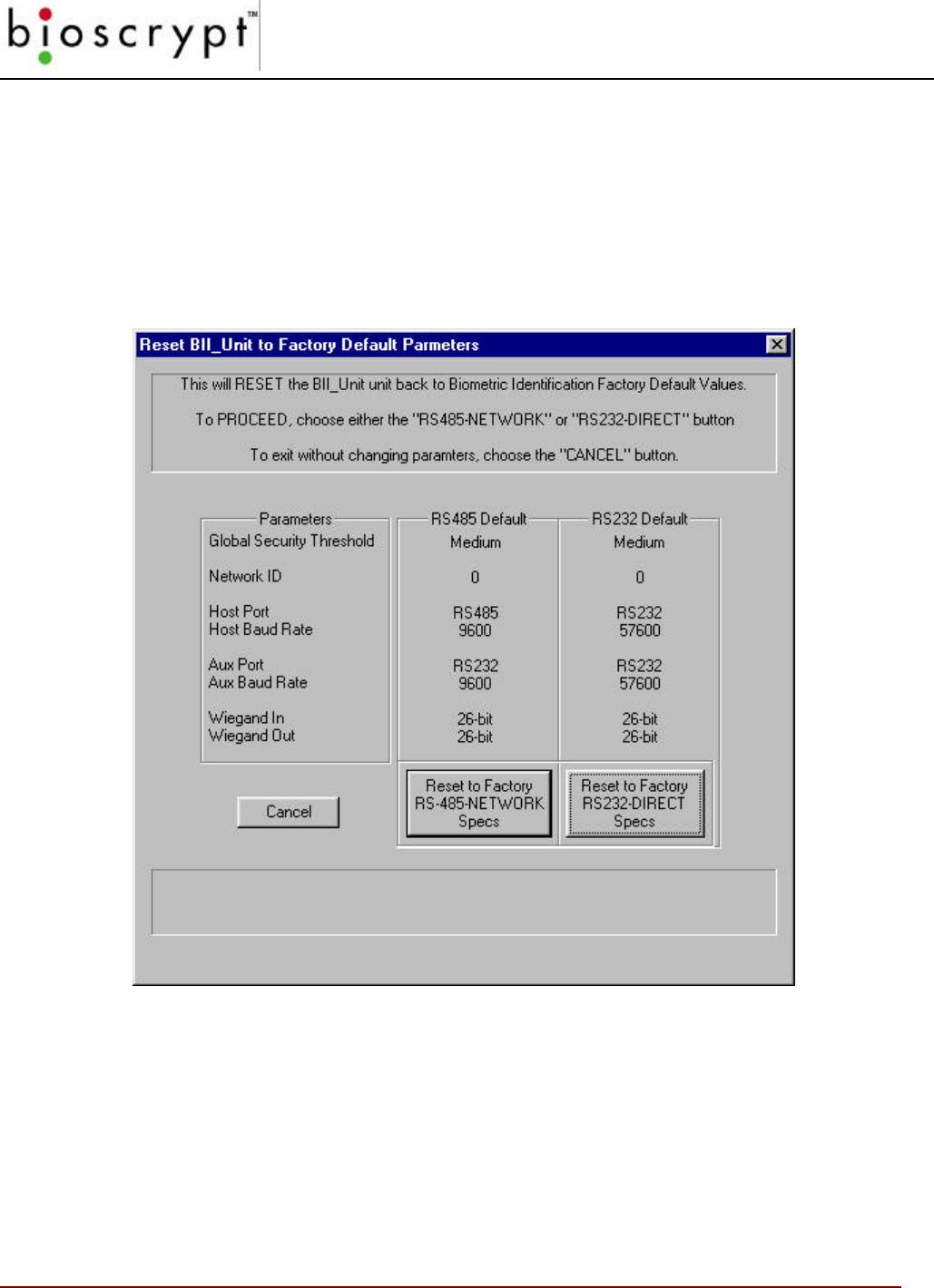
Two options are given: RS-485 Default and RS232. The associated Factory Default settings
are identified for each option. Proper communication must be established with the reader
before this operation can successfully performed.
Press the button of the option desired and each Parameter will be set on the reader.
Figure 39: Reset Parameters
NOTE: A Network ID of –1 is NOT valid for this operation.
TEMPLATE CONVERSION
76 © Copyright 2002, Bioscrypt Inc. All rights reserved.
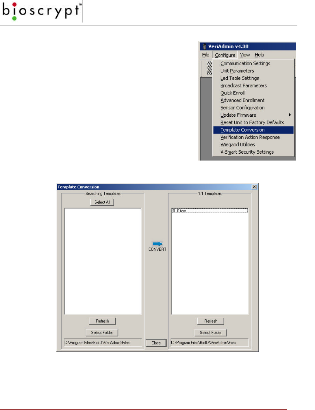
Template Conversion
Choosing the Template Conversion menu item will
allow the user to convert templates stored on the PC
from the larger Searching templates used with the V-
PASS to the smaller 1:1 Verification Templates used
with the VeriProx and VeriFlex (see Appendix C for
details).
It is recommended that only advanced users attempt to
perform this operation. Please call Bioscrypt Technical
Support with any questions.
Figure 40: Template Conversion Menu
Figure 41: Template Conversion Dialog

TEMPLATE CONVERSION
77 © Copyright 2002, Bioscrypt Inc. All rights reserved.
Using the Template Conversion Dialog, users can choose the Source (V-PASS template)
and Destination (VeriProx/VeriFlex template) directories by pressing the appropriate
STORAGE FOLDER button and selecting the desired directory.
Next, highlight the V-PASS Searching templates that you wish to convert (or press the
SEL ALL button to select all appropriate templates in the selected directory).
Pressing the Right Arrow button will convert all selected V-PASS templates to
VeriProx/VeriFlex templates. The names will remain the same, but the extension will
change from “.mtm” to “.tem”.
VERIFICATION ACTION RESPONSE
78 © Copyright 2002, Bioscrypt Inc. All rights reserved.
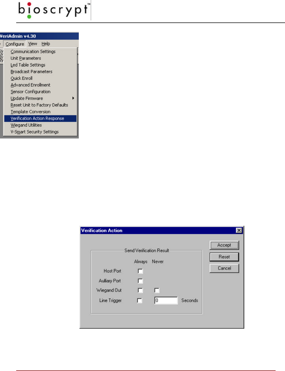
Figure 42: Verification Action Response
Verification Action Response
Choosing the Verification Action Response menu item will allow users to
customize the way the unit responds to a Verification Action.
Under Normal operations, the Veri-Series unit will respond based on
how a Verification Action was initiated. When a Wiegand INPUT
initiates the action, a Wiegand OUTPUT is used to respond. When a
Verification Action is initiated over a communications port by using the
Bioscrypt DLL or low-level commands (described in the MV1100 SDK),
then the response packet is
returned on the same
communication port (either HOST or AUX). This
menu allows the user to select other Verification Responses in addition to the normal
response.
The Line Trigger is a signal line that will trigger for the defined number of seconds on a
successful verification. Although not a true TTL level signal, this trigger could be used to
initiate a relay or other device. The Line Trigger is the GREEN wire on the Veri-Series
pigtail.
It is recommended that only advanced users who are working with the SDK and writing
their own custom software attempt to enable the HOST or AUX ALWAYS operations.
Please call Bioscrypt Technical Support with any questions.
Figure 43: Verification Action Dialog
WIEGAND UTILITIES
79 © Copyright 2002, Bioscrypt Inc. All rights reserved.
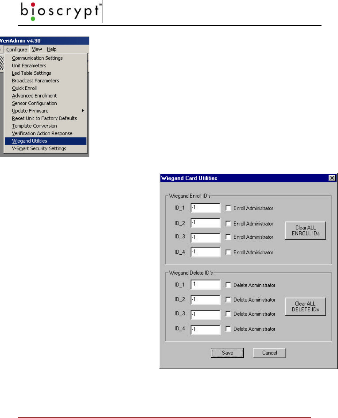
Figure 45: Wiegand Card Utilities Dialog
Wiegand Utilities
(* requires firmware v3.2 or higher)
Choosing the Wiegand Utilities menu item will allow users to define
specific Administrator IDs that will not require a fingerprint to initiate the
ENROLL and DELETE actions.
Under Normal operations, ENROLL and DELETE COMMAND CARDS
require a fingerprint verification to be performed that ensures the correct
person is using the ADMIN card.
The Wiegand Utilities Dialog allows Administrators to create specific IDs
that can initiate the following operations:
Figure 44: Wiegand Utilities
- Create ENROLLMENT
Administrator Command Card
- Enroll User/Card
- Create DELETE Administrator
Command Card
- Delete User/Card
By entering a Card ID in the
appropriate box and pressing the
SAVE key, that ID will be stored in
the VeriSeries Unit memory. When
a card that contains that ID is
presented to the VeriSeries
Product, the appropriate action will
be initiated.
This feature has been added to
allow installers to create ENROLL
and DELETE ADMIN Command
Cards without a PC if the unit has
been properly pre-configured for
specific card IDs by using this
feature. Once these initial cards
have been created, we recommend
deleting the pre-configured IDs with
the CLEAR ALL buttons.

GETTING SERVICE AND SUPPORT
80 © Copyright 2002, Bioscrypt Inc. All rights reserved.
Getting Service and Support
Bioscrypt, Inc. is available to provide information and assistance. Contact
Bioscrypt using methods discussed below.
Before calling, copy down the following version information about your unit:
• Software
• DLL
• Algorithm
• Kernel
• PIC
• ESI (if applicable)
This can be found in the Help menu under the About menu. The ESI version can
be found under the Smart Card Manager in the upper left (V-Smart only).
Technical Support
For assistance with technical matters, contact the Technical Support
Department by sending e-mail to support@bioscrypt.com. To speak directly
with a technician, call (818) 501-3908.
Customer Service and Sales Support
Bioscrypt is here to assist you with your questions. Contact our Customer
Service and Sales support departments by calling (818) 501-3908.
World Wide Web Site
See our World Wide Web site for breaking information, and other services. The
address is www.bioscrypt.com.

APPENDIX A – QUALITY AND CONTENT
81 © Copyright 2002, Bioscrypt Inc. All rights reserved.
Appendix A – Quality and Content
Section A.1 - Basic Biometric Concepts
Biometric Definitions
Enrollment is the operation of scanning a fingerprint, determining the
quality of the fingerprint scan, and storing a good template with associated
data within the memory of the Veri-Series product.
Verification is the operation of presenting the user ID, either by waving a
proximity card or typing the ID into the Verify dialog box, requesting the
user to place their finger on the fingerprint sensor, scanning the finger,
comparing the current scan against stored fingerprint templates for that
user, and then notification of a successful validation or a failure.
Searching is the operation of the user placing their finger on the V-PASS
fingerprint sensor, scanning the finger, comparing the current scan against
ALL stored fingerprint templates for V-PASS unit, and then notification of a
successful validation or a failure. Searching is only possible on a V-PASS.
Fingerprint Template is the term used to describe the data stored on the
VeriProx that mathematically represents the ridge pattern of an enrolled
fingerprint. This data is not the raw image of the fingerprint, but the result of
processing a raw image through our unique algorithmic process, preparing
the data for later comparisons, and compressing the data for maximum
storage. An image of the uncompressed template data does resemble the
raw image, but whereas a raw image is 90K bytes, the compressed
template is only 348 bytes for the VeriProx or VeriFlex and 2352 bytes for
the V-PASS.
Fingerprint Core is the term used to describe distinguishing print
characteristics usually found in the area of the print where the topography
shows the tightest curvature. Although the entire fingerprint has significant
data, the “core” is the most data-intensive area and therefore very
important.
APPENDIX A – QUALITY AND CONTENT
82 © Copyright 2002, Bioscrypt Inc. All rights reserved.
Scanning an Image
When the unit properly reads a fingerprint, it looks for image quality and fingerprint
content. When a raw image is collected from the sensor, the Veri-Series unit searches
for the fingerprint core.
Content scores are based upon the amount of non-ambiguous data in the region
of the core. The higher the content, the greater the degree of useful information.
See Section A.3 for a thorough discussion of content
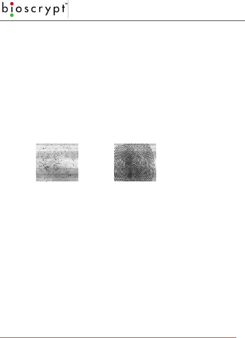
Quality scores are based on how well the ridge pattern is defined within the image.
For best image quality, be sure that the sensor window is clear of dirt, residue, or
other material that can block the BII_Units view of the fingerprint. See Section A.3
for a thorough discussion on quality.
Once the image is scanned, the BII_Unit then creates and stores the resulting
fingerprint template.
Storing User Templates on the Unit
The Veri-Series unit recognizes users by matching current images to stored
templates of previously enrolled fingerprints. Along with the fingerprint, the
VeriProx and VeriFlex require a proximity card with a unique user ID number.
The Veri-Series readers allow associating multiple fingerprints with a single
Template ID. Each instance of a template with a specific ID has a unique index (up
to 256 indices possible (0-255)). This allows a VeriProx and VeriFlex users to have
a single proximity card, but be able to enroll multiple fingers. During
VERIFICATION, a user waves their card at the VeriProx / VeriFlex reader and
places their finger on the sensor. The unit will then scan the current fingerprint and
compare it against all enrolled templates for that specific ID. If there are multiple
templates enrolled under one ID, then the VeriProx / VeriFlex will check templates
in the numerical order based on their index.
Example: On Card # 123, a person ENROLLs both their left and right index
fingers. The next time that user goes to verify, they wave Card #
123 and place a finger on the sensor. The VeriProx scans the
current finger and compares it against the first template (the right
index finger, Template ID 123 0). If a match is found, the
VERIFICATION is PASSED and the operation ends. If a match is
not found, the VeriProx will check the second print (the left index
finger, Template ID 123 1). If a match is found, the
VERIFICATION is PASSED and the operation ends. If the match

APPENDIX A – QUALITY AND CONTENT
83 © Copyright 2002, Bioscrypt Inc. All rights reserved.
is not found and since all templates have been compared, the
VERIFICATION is FAILED.
NOTE: The initial finger scan takes ~0.5 seconds and each comparison
takes ~0.5 seconds. So if the first template results in a successful
verification, the total time is ~1.0 seconds. Successful verification
on the second templates requires ~1.5 seconds, and so on.
Section A.2 - Proper Finger Placement
The basics for successful operation of the Veri-Series units are simple but important.
System performance improves dramatically with consistent finger placement. It is
important to make sure that the position of the finger allows the unit to record the unique
features of the print. Here are the steps to follow for trouble-free fingerprint recognition.
• Bioscrypt has designed the Ridge-Lock to create “simple user instruction” and
“consistent” finger position. With the fingertip raised, position the finger so that
the Ridge-Lock rests comfortably within the first indentation of the finger. Next,
lower the finger onto the sensor and apply moderate pressure.
Common mistakes
Correct finger placement is a significant component for reliable fingerprint imaging.
The following list some common mistakes to avoid.
• Sliding the fingertip into place instead of lowering it onto the sensor will cause
distortion of the fingerprint and will degrade image quality. Keep the fingertip
raised while locating the Ridge-Lock, then lower the fingertip.
• Rotating the finger into position also will cause distortion of the fingerprint,
subsequently making verification less reliable.
• Positioning the finger to one side and leaving a portion of the sensor exposed will
degrade image quality.
• Placing the finger at an angle to the finger guide is another common mistake.
Rotation of the fingertip will not provide a reliable image of the fingerprint.
Image quality
Dry skin is another factor that can contribute to an unreliable image of a fingerprint. A
normal amount of moisture on the skin makes the ridges and valleys of the fingerprint
stand out to the sensor. Too little moisture makes the image “noisy” and will “cause

APPENDIX A – QUALITY AND CONTENT
84 © Copyright 2002, Bioscrypt Inc. All rights reserved.
the Veri-Series unit to reject the image during processing. Lightly moisturizing the
finger will enhance the contrast of the print and provide more reliable verification. The
increased sensitivity of the silicon sensor is dramatically reducing problems in this
area.
Image consistency
Once a user’s fingerprint template has been enrolled, the best performance in the
candidate matching process depends on consistency. Obviously, the user must use
the same finger for ID verification as was used to form the original template. It also is
important to position the finger correctly for each verification, as was done when the
template was enrolled, so the Veri-Series unit “sees” approximately the same
information each time.
APPENDIX A – QUALITY AND CONTENT
85 © Copyright 2002, Bioscrypt Inc. All rights reserved.
Section A.3 - Using Content and Quality during Enrollments
As described in section A.1, Quality and Content scores are returned in the enrollment
process. These scores give an indication of the performance of the template enrolled. To a
large degree, the verification algorithm compensates for deficiencies in image quality and
loss of information content. Nonetheless, knowledge of these parameters and what they
mean helps ensure optimal performance.
False Acceptance and False Rejection
In order to understand the effects of poor image quality and poor information content it
is necessary to understand how to measure performance. Performance of the Veri-
Series unit is presented in terms of False Rejection and False Acceptance.
False Rejection indicates that the unit incorrectly rejected a fingerprint that
corresponds to the person’s template. False Rejections rarely occur and
primarily result from the inability to get a good image of the finger.
False Acceptance indicates that the unit accepted a fingerprint that does
not correspond to the template it was compared against. False
Acceptances also are rare and primarily result when a fingerprint template
is characterized by low information in the enrolled print.
The algorithm on the Veri-Series units has been tuned so that the false acceptance
and false rejection rates are equal at the medium security level (level 3), delivering the
industry leading accuracy. This is known as the Equal Error Rate. Increasing the
security (e.g., changing the security level from 3 to 1) will decrease the chance for
false acceptance at the expense of increased false rejection. Reducing the security
(e.g., changing the security level from 3 to 5) will decrease the chance of a false
rejection at the expense of false acceptance. The table below indicates the expected
error rates at the different security levels.
Security Level False Rejection Rate False Acceptance Rate
Very Low (5) 1 / 10,000 1 / 100
Low (4) 1 / 5000 1 / 200
Medium (3) 1 / 1000 1 / 1000
High (2) 1 / 200 1 / 5000
Very High (1) 1 / 100 1 / 20,000
APPENDIX A – QUALITY AND CONTENT
86 © Copyright 2002, Bioscrypt Inc. All rights reserved.
Quality
The quality score is based on how well the ridge pattern is defined within the
fingerprint image that was enrolled. In other words, quality measures how clearly
the unit imaged the fingerprint. Poor quality enrollments can result in an elevated
rate of false rejection making it difficult for the user to verify reliably.
The score is given in stars («) and ranges from zero to five stars, with five being
the best quality (rarely obtained) and zero being the worst. Quality scores of three
stars and higher perform well with the Bioscrypt verification algorithm. In this
range, the algorithm readily compensates for differences in fingerprint quality. It
statistically is still true that the larger the quality score the better the performance
of an enrollment.
As a general rule of thumb, quality scores less than three stars require intervention
on the part of the Enroller or administrative software. Sources of low scores
include dry fingers and dirty sensors.
If the quality score falls below three stars, Bioscrypt recommends the following
options:
• Ensure that the sensor and finger are clean.
• If the finger and sensor are clean and a dry finger is suspected, try re-enrolling
one more time, leaving the finger on the sensor for several seconds prior to
enrollment. Frequently finger moisture accumulates over time to provide a
good image.
• Fingerprint quality can vary among individual fingers for the same person. Try
enrolling an alternate finger to see if the score improves.
• Alter the security level for that particular template by decreasing the threshold a
minimum of 1 level (e.g., change the value from medium [3] to low [4]). This will
offset the false rejection for that template by making it easier to match. If use of
that template indicates that raising the threshold one level still produces false
rejections, try setting the value to its lowest security (level 5).
Warning:Decreasing a template’s security may increase the risk of a
false acceptance for that template.
Very Low
Quality
Very High
quality
APPENDIX A – QUALITY AND CONTENT
87 © Copyright 2002, Bioscrypt Inc. All rights reserved.
A thorough enrollment procedure will ensure streamlined and reliable verification
for users. It is recommended that all four options be performed in the order listed
above to maximize the performance of the device.
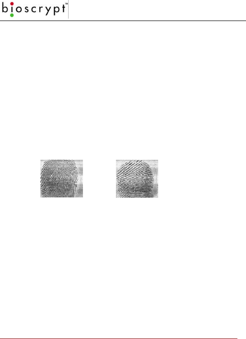
Content
The Content score is based upon the amount of usable information the Veri-Series
unit sees in the fingerprint. Templates that are characterized by low content scores
may result in elevated rates of false acceptance.
Again, the score is given in stars («) and ranges from zero to five stars, with five
being the most content and zero being the least. Content scores of three stars and
higher perform well with the Bioscrypt Algorithm. In this range the algorithm has
enough information to distinguish between different fingerprints with a high level of
accuracy. Templates with content scores above two stars do not vary in terms of
the error rates.
Content scores less than three stars require intervention on the part of the Enroller
or administrative software. Sources of poor content include improper finger
positioning and extremely bland fingerprints.
If the content score falls below three stars, Bioscrypt recommends the following
options:
• Try re-enrolling the same finger if finger positioning seems to be the issue
(see section A.2). Ensure that the user can comfortably place the finger on
the sensor while maintaining the core region in the image.
• Fingerprint content can vary among individual fingers for the same person.
Try enrolling an alternate finger to see if the score improves.
• Alter the security level for that particular template by increasing the
threshold a minimum of 1 level (e.g., change the value from medium [3] to
high [2]). This will offset the false acceptance for that template by making it
more difficult to match. If use of that template indicates that raising the
threshold one level still produces false rejections, try setting the value to its
highest security (level 1).
Very High
Content
Low Content
APPENDIX A – QUALITY AND CONTENT
88 © Copyright 2002, Bioscrypt Inc. All rights reserved.
Warning: Increasing a template’s security may increase the risk of a false
rejection for that template.
A thorough enrollment procedure will ensure streamlined and reliable verification
for users. It is recommended that all three options be performed in the order listed
above to maximize the performance of the device.
Content and Quality Summary
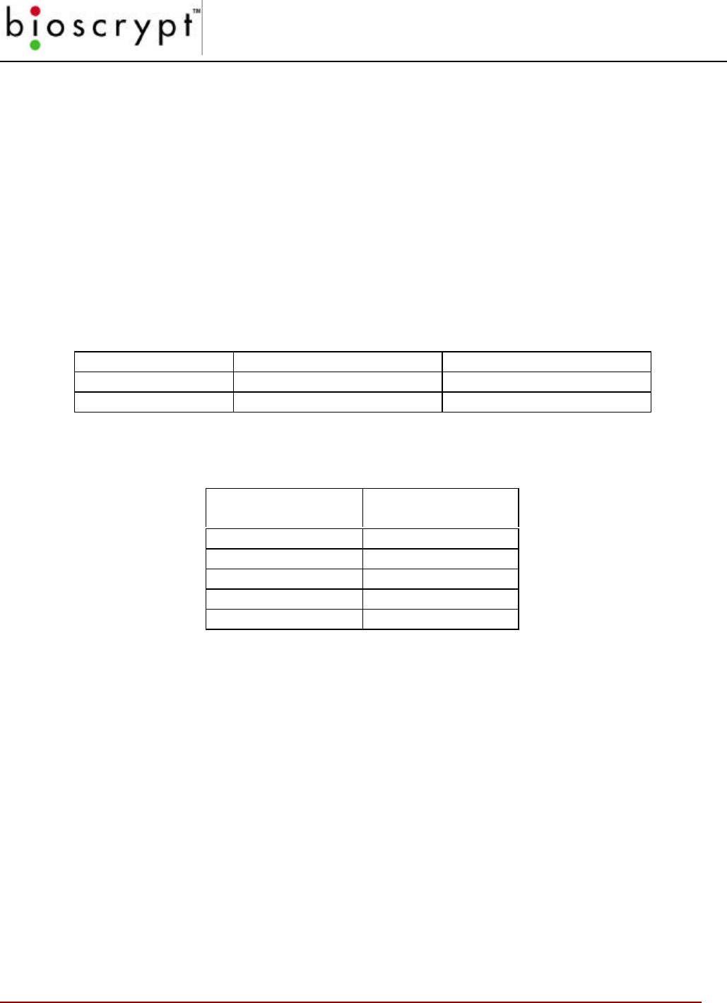
Table 1: Quality and Content Minimum Thresholds
Score Poor Range Normal Range
Quality Less than three stars Three or more stars
Content Less than three stars Three or more stars
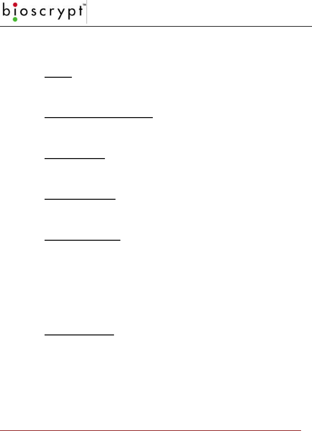
Table 2: VeriAdmin Management application map of score versus category
Score Quality/Content
Category
«Very poor
«« Poor
««« Fair
«««« High
««««« Very high
Recommended Enrollment Process
• Have the user pick one of the following fingers for enrollment: Left Index,
Left Middle, Right Index, or Right Middle.
• Enroll the chosen finger and note the quality and content results.
• If either is below the minimum threshold, follow the directions outlined in the
previous section.
• If both are above their minimum thresholds, either accept the created
template, or attempt another finger trying to achieve the best quality
possible.

APPENDIX A – QUALITY AND CONTENT
89 © Copyright 2002, Bioscrypt Inc. All rights reserved.
• If multiple fingers are attempted and only one finger is required, choose the
template where both quality and content are above the threshold, and which
the quality is maximized.

APPENDIX B – UNDERSTANDING THE
BROADCAST OPTION IN RS-485 BASED NETWORKS
90 © Copyright 2002, Bioscrypt Inc. All rights reserved.
Appendix B – Understanding the BROADCAST option in
RS-485 Based Networks
The BROADCAST feature allows a command to be sent to ALL units connected on the
same PC COMM Port. Using a NETWORK ID of –1 enables “Broadcast Mode”. Although
this is often a very convenient feature, it also has some inherent issues that the user should
be aware of and understand. Bioscrypt recommends that only advance users attempt the
BROADCAST features.
NO REPLIES. When in Broadcast mode, no replies from the receiving unit are possible.
This is because that since all units receive the command at the same time, all units would
then normally reply at the same time. On a RS485 network, it more then one unit is
communicating at the same time, the communications electrically collide and cannot be
understood. This is an inherent shortcoming of the RS485 protocol. This collision will also
happen if 2 or more units are the same NETWORK ID, since they will both respond at the
same time and cause the same problem. When in Broadcast mode, the Bioscrypt readers
are instructed NOT to REPLY.
NO ERROR CHECKING. The Bioscrypt communication protocol has various error
checking methods built into the interface. This error checking requires two-way
communication between the PC and the Bioscrypt reader to ensure that command packets
where received and all data contained. Because NO REPLIES are possible, the error
checking is disabled in Broadcast mode.
This can become an issue when using a network of Bioscrypt readers since the reader itself
cannot process a communication packet during Verification. Although this time is very
short, if a command is received during portions of a Verification the unit would normally
respond with a BUSY error code. However, if in Broadcast mode, no response can be
given and the VeriAdmin will not know that the command was ignored by that particular unit
(even though it would have been accepted by all other units.) Manual verification is often
required to ensure all units successfully received a Broadcast command. An example of
this can be seen in the BROADCAST PC TEMPLATE section. The VeriAdmin Software will
Broadcast the TRANSFER command, but then manually verify that the template was
successfully transferred to each and every unit after the Broadcast command is complete.
Since Broadcast commands cannot have the Bioscrypt reader reply, using a Network ID
has been disabled in Reset to Factory defaults and Sensor Settings.
NOTE: A Broadcast command will be received by all units on the same PC COMM port. If
a network consists of multiple COMM ports, the Broadcast command will have to be sent on
each COMM port in order to reach all units on the network. This is automatically done by
the VeriAdmin Software for BROADCAST PC TEMPLATES and for all commands in the
BROADCAST PARAMETERS window based on the UNITIDS.DAT file. However, this is
not for other commands where the user specifies a Network ID of –1.

APPENDIX C – V-PASS TEMPLATE DIFFERENCES
91 © Copyright 2002, Bioscrypt Inc. All rights reserved.
Appendix C – V-PASS Template Differences
The V-PASS product is similar in size and shape to both the VeriFlex and VeriProx
products. However, it incorporates a very different biometric comparison process. The
VeriFlex and VeriProx perform a 1:1 verification. One finger is compared with one template
to decide if there is a match. A Template ID is mandatory to determine which of the stored
templates to compare with the current live fingerprint image.
The V-PASS performs a “searching” algorithm that will compare the current live fingerprint
image with ALL templates that reside on the V-PASS unit (up to 200 with firmware version
3.0). This is often referred to as 1:many (one to many) or “identification”. Whereas the
VeriProx and VeriFlex are typically used with a proximity card or external device to indicate
a user’s ID, the V-PASS no longer requires this extra form of identification, only the
fingerprint is required.
To perform this quick database search of all enrolled templates, the V-PASS requires a
fingerprint template that is different then the fingerprint templates required for the VeriFlex
and V-Pass. The VeriFlex / VeriProx templates are 348 bytes of data, whereas the V-PASS
template is 2,532 bytes of data.
The V-PASS template contains all the data from a VeriFlex/VeriProx template and more.
Bioscrypt provides a way to generate a 1:1 VeriFlex / VeriProx template from a V_PASS
template. This conversion is available in our SDK for software developers, or as part of the
VeriAdmin Management Software for end-users.
Users should be aware of the following:
1. V-PASS templates are different then VeriFlex / VeriProx templates.
2. V-PASS templates should use the default extension of “.mtm”
3. VeriProx / VeriFlex templates should use the default extension of “.tem”
4. Only a V-PASS can create (“enroll”) a V-PASS template.
5. A V-PASS template CAN BE converted to a VeriFlex / VeriProx template.
6. A VeriProx / VeriFlex template CANNOT be converted to a V-PASS template.
7. Administrators need to be aware of these differences if BOTH products are used.
8. A Veri-Series unit will reject a template if the wrong type is sent. This means that a
VeriProx / VeriFlex will return an error if a V-PASS template is sent to that unit. The
same is true if a V-PASS unit is sent a VeriFlex / VeriProx template.
9. Administrators should use caution when attempting Broadcast commands on a
“Mixed” Network.. Broadcast commands will work, but #8 above will apply. Contact
Bioscrypt Technical Services for more information.

APPENDIX C – V-PASS TEMPLATE DIFFERENCES
92 © Copyright 2002, Bioscrypt Inc. All rights reserved.
For installations using a “Mixed” network where both V-PASS units and VeriFlex / VeriProx /V-
Smart units are used, Bioscrypt recommends the follow guidelines to help manage templates:
1. A PC-based enrollment stations using the VeriAdmin software should be used for
all template enrollments.
2. All enrollments should be done using a V-PASS and stored on the PC.
3. V-PASS templates can be converted to VeriProx / VeriFlex templates using the
VeriAdmin Software (see the Template Conversion section). After this process,
the Administrator will have both a V-PASS compatible template and a VeriProx /
VeriFlex compatible template for each user.
4. Use the Bioscrypt designated extensions of “.tem” for VeriFlex / VeriProx
templates and “.mtm” for V-PASS templates.
Example:
• PC Enrollment station is setup with an attached V-PASS unit and running the
VeriAdmin Management software.
• Using the Advanced Enrollment dialog, the Administrator will enter an ID (ex:
1122) and sample enroll 3 different fingers and chose the best one as indicated
by the software.
• This fingerprint template will be save to the PC (ex: 1122_0.mtm).
• The Administrator will use the Template Conversion utility to create a VeriFlex /
VeriProx template (ex: 1122_0.tem).
• Template 1122_0.mtm will then be transferred to all V-PASS units.
• Template 1122_0.tem will then be transferred to all VeriFlex / VeriProx / V-
Smart units.

APPENDIX D – V-SMART OPERATIONS
93 © Copyright 2002, Bioscrypt Inc. All rights reserved.
Appendix D – V-Smart Operations
The V-Smart product is similar in size and shape to both the VeriFlex and VeriProx
products. However, it incorporates a new method for template management. The V-Smart
incorporates a contactless smart card reader using MIFARE technology. This allows a
user’s template to be written to a smart card during enrollment and then later read from the
smart card during verification. Since the template is stored on the card itself, there is no
need for network-based template management operations typically associated with
biometric installations.
Smart cards used by the V-Smart can now be used by another application. V-Smart
operation uses only the part of the Smart Card defined by the layout, so that other
applications can now use any remaining free sectors.
Contact your Bioscrypt Sales representative when purchasing smart cards to ensure they
will work correctly with the V-Smart.
Administrator’s Note
The Administrator / Enroller needs to understand the different states that the V-Smart
operates to effectively use the unit. The most important aspect to understand is the
difference between HOST and SLAVE mode. HOST mode is the normal operating state of
the V-Smart. In this mode, the unit is actively looking for a smart card with a template on it.
When a card is seen, one or both templates is automatically read and a Verification action is
started. While the Verification action is happening, the V-Smart cannot process other
commands coming over the AUX channel from the PC. The only time this becomes an
issue is when using the VeriAdmin software.
When writing a template to the smart card as part of the enrollment process, it is important
to wait for VeriAdmin to display a message saying, “PLACE SMART CARD CLOSE TO
READER”. If the Administrator places the card before the message, the V-Smart may treat
this as described above, and initiate a Verification action. The V-Smart will then be busy
trying to verify a live image and will not be able to process the Enrollment. You can tell
when this happens because the top LED will turn yellow. If this does happen, simply place
a finger and let the V-Smart complete the Verification attempt. Then press the SAVE TO
SMART CARD button and wait for the “PLACE SMART CARD CLOSE TO READER”
prompt.
NOTE: It is essential that the Administrator read and fully understand the
information presented in Appendix E: Administrator SiteKey Management. Failure to
use the V-Smart in the proper way can make the V-Smart less secure and potentially
unusable if Site Keys are forgotten or compromised.
APPENDIX D – V-SMART OPERATIONS
94 © Copyright 2002, Bioscrypt Inc. All rights reserved.
V-Smart Terminology
V-Smart – Term used to designate the complete hardware product. The V-Smart
actually contains an embedded MV1200 with expanded I/O functionality, an
External Storage Interface (ESI) module and a MIFARE smart card reader.
External Storage Interface (ESI) – This module is internal to the V-Smart and
acts as an interface between the MV1200 and the smart card reader. External
pigtail wires connect the MV1200 and ESI together.
Primary Template – This is the template that resides in the first template slot on
the smart card. When a verification is initiated, this primary template is the first
fingerprint that is used in that verification process.
Secondary Template – This is an optional second template stored on the smart
card. Currently, in the v5.80 (or later) V-Smart firmware, this second template will
also be used in the verification process if the primary template verification fails.
Administrator SiteKey – This is a key (or password) used by the V-Smart to
encrypt data stored on the smart card. This key is stored on the ESI and must
match the key used by the smart card in order for the V-Smart to read the smart
card data. See the next section for further details regarding Administrator Site
Keys.
WARNING! It is extremely important that Administrators do not forget the SiteKey
used. If the SiteKey is forgotten, the administrator will not be able to ENROLL,
DELETE or read templates from the smart card, nor will they be able to CHANGE
the SiteKey.
Site Key Verification – Certain VeriAdmin and V-Smart processes are only
allowed if the Administrator enters the correct Site Key. The SiteKey entered in
VeriAdmin must match the key stored on the V-Smart and the key used to encrypt
the smart card data. See Appendix E for father details.
APPENDIX D – V-SMART OPERATIONS
95 © Copyright 2002, Bioscrypt Inc. All rights reserved.
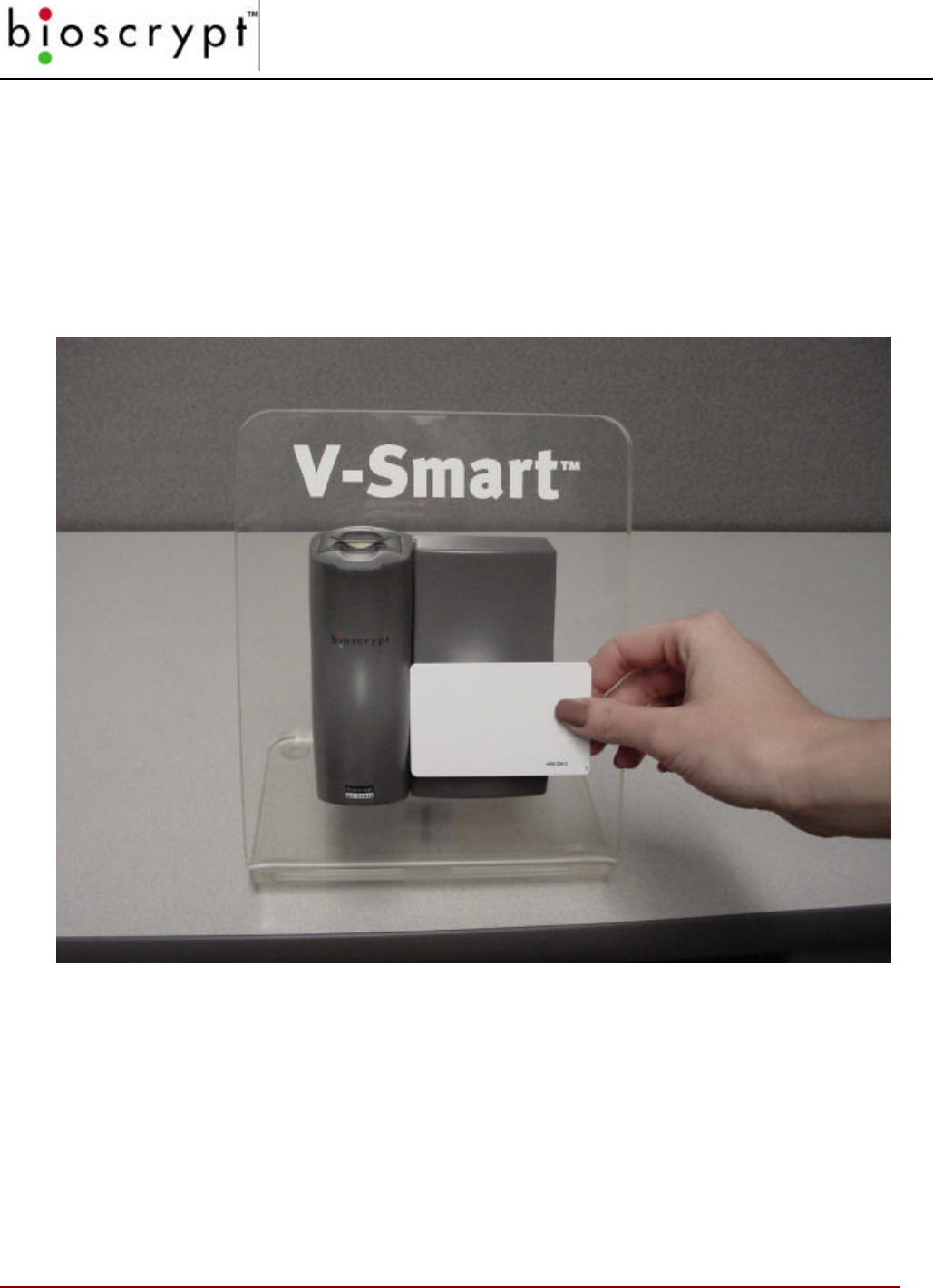
V-Smart Smart Card Placement
The picture below demonstrated the proper placement of the smart card so the V-Smart can
read the data stored on the card or write data to the card.

APPENDIX D – V-SMART OPERATIONS
96 © Copyright 2002, Bioscrypt Inc. All rights reserved.
Section D.1 – HOST Mode versus SLAVE Mode Operation
The V-Smart has two modes of operation that the Administrator needs to be familiar with.
These are HOST mode and SLAVE mode.
HOST MODE
HOST mode is the normal mode of operation and simply means that the V-Smart is waiting
for a smart card to be presented to the unit. When a smart card is “seen”, the card Site Key
(see next Appendix) is compared with the V-Smart’s Site Key. If they match, the template
is read from the card and the V-Smarts attempts a Verification operation. The top LED will
turn amber indicating the user should “PLACE FINGER ON SENSOR”. When a finger
placed, a live image is recorded. When the live image is done recording, the top LED will
go off. At this time, the user can remove their finger. The V-Smart will then compare the
live image against the template read from the smart card. If a successful match made, the
top LED will turn GREEN. A RED LED indicates a failed comparison. Once a Verification
attempt has been made, the card must be moved away from the reader and then brought
close again to re-attempt Verification.
SLAVE MODE
SLAVE mode is when the V-Smart is communicating with the PC. When a serial command
is received by the V-Smart on the AUX communications port, SLAVE mode is automatically
entered. While in SLAVE mode, the V-Smart will NOT make Verification attempts when a
card is “seen”. This makes it easier for Administrators to place the card, near the reader
and perform various operations like enrollments without the unit performing a Verification
just because a card is sensed. The V-Smart will return to HOST mode in one of two ways:
1) a command is sent to the V-Smart telling it to specifically return to HOST mode
2) 180 seconds have passed since the last communication on the AUX port
In VeriAdmin, when you bring up the SMART CARD MANAGER, the V-Smart is put into
SLAVE mode because a STATUS is sent to the ESI as the dialog is brought up. When the
user exits the SMART CARD MANAGER by pressing the OK or CANCEL buttons,
VeriAdmin will instruct the V-Smart to return to HOST mode.
APPENDIX D – V-SMART OPERATIONS
97 © Copyright 2002, Bioscrypt Inc. All rights reserved.
Section D.2 – Transferring a Template to a Smart Card
VeriAdmin version 4.00 adds a new capability to transfer a previously enrolled fingerprint
template to a smart card. The user can either transfer a template from the PC to a smart
card or from the internal memory on the V-Smart to a smart card. To transfer a previously
enrolled template that is currently stored on the PC to a smart card, press the FROM PC à
SMARTCARD button. The user will be allowed to browse to the desired PC template.
Once the template is chosen, the EDIT TEMPLATE dialog is brought up and the template
data is displayed. Pressing the SAVE TO SMART CARD button will then attempt to write
template data to the smart card. This process involves a SiteKey verification window to
appear (see appendix E). Once the proper Site Key is entered, the user is prompted to
APPENDIX D – V-SMART OPERATIONS
98 © Copyright 2002, Bioscrypt Inc. All rights reserved.
place the smart card near the V-Smart. When this is done, the template is then copied to
the smart card.
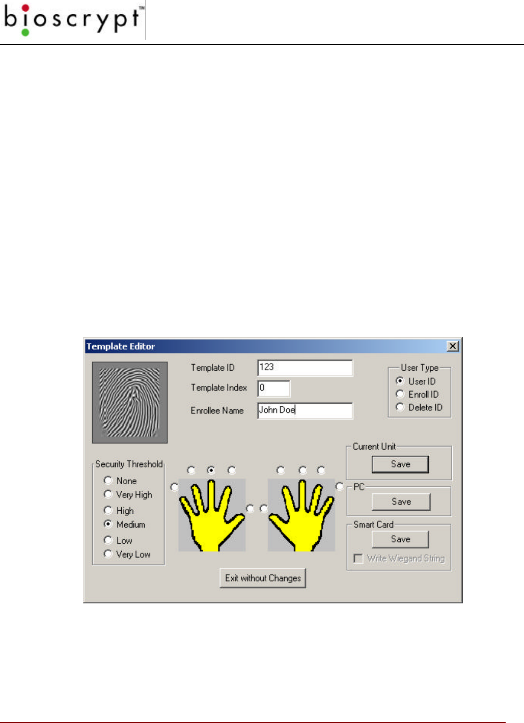
Section D.3 – Enrolling a Template Directly to a Smart Card
Using VeriAdmin, the smart card Enrollment process is very similar to a typical enrollment
procedure as described in the QUICK ENROLL section or in the ADVANCED TEMPLATE
ENROLLMENT section. Once a finger is registered and a template created and accepted,
the EDIT TEMPLATE window is displayed as described in the TEMPLATE MANAGER
section. However, for release v4.0 and above the EDIT TEMPLATE window has been
modified to allow for saving the template directly to a Smart Card. As seen below, options
now exist to save the template to the CURRENT UNIT, the PC, or a SMART CARD. By
pressing the SAVE button under SMART CARD, the V-Smart will attempt to write the
template to a smart card held near the smart card reader. Note that a SiteKey verification is
performed before the data is written to the smart card (see appendix E for details).
APPENDIX D – V-SMART OPERATIONS
99 © Copyright 2002, Bioscrypt Inc. All rights reserved.
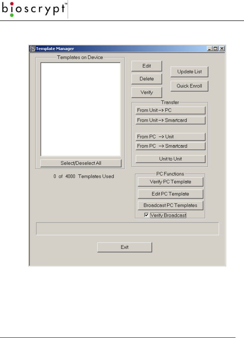
Section D.4 – Using the Smart Card Manager
VeriAdmin version 4.00 adds a new toolbar option (shown above) for accessing the Smart
Card Manager dialog box. Pressing the “SMART” button will bring up a dialog box like the
one shown below.
APPENDIX D – V-SMART OPERATIONS
100 © Copyright 2002, Bioscrypt Inc. All rights reserved.
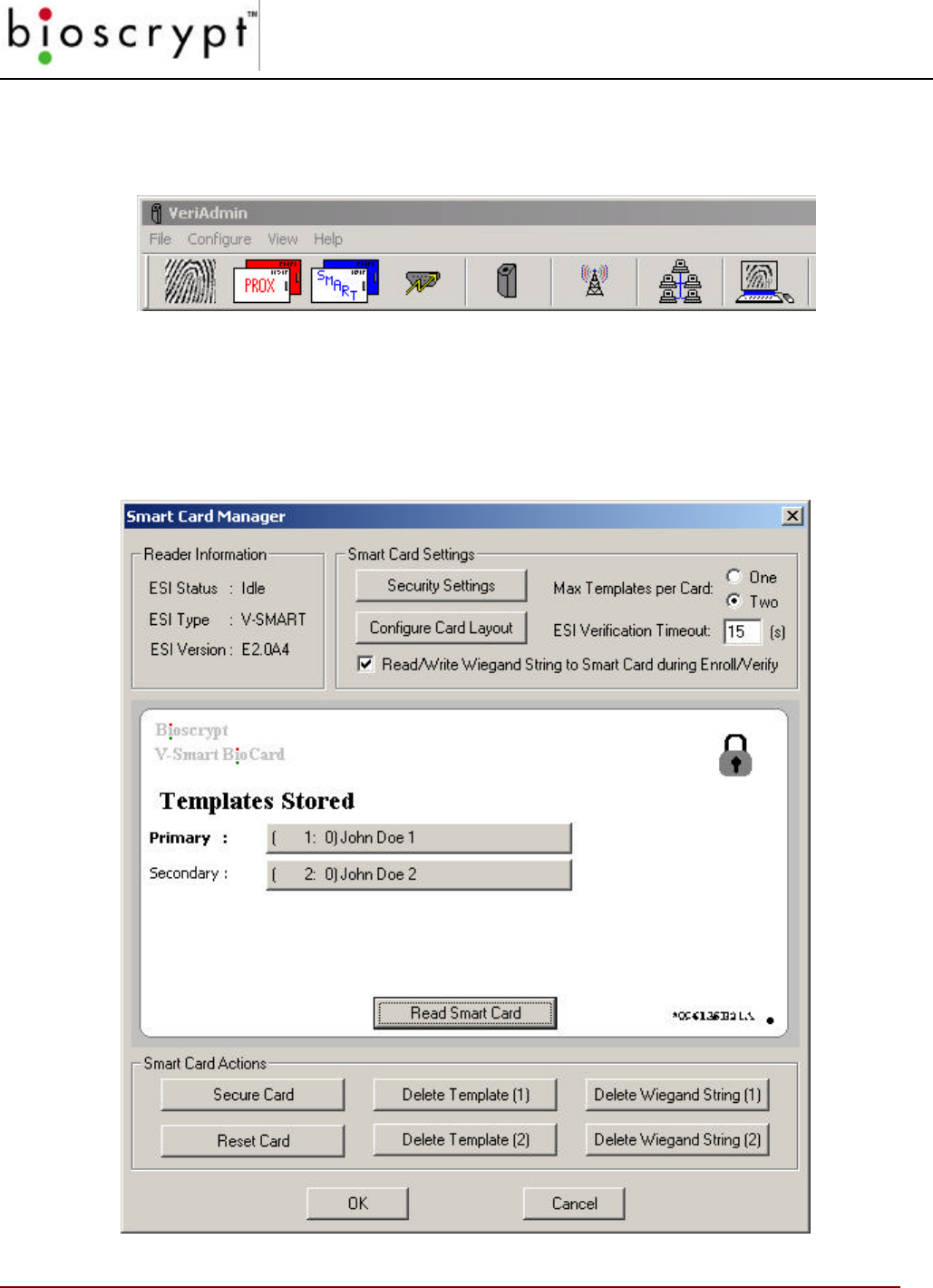
This dialog initially shows the ESI information and a blank card. Pressing the READ
SMART CARD button will instruct the V-Smart to read the template list from the card and
display the list of stored templates. In the example shown, there are two templates. The
display shows the Template ID:INDEX followed by the NAME field from the template. The
upper right hand corner of the card has symbol indicating the card is secured.
Pressing either template button (primary or secondary) will instruct the V-Smart to attempt
to read the full fingerprint template data from the smart card. VeriAdmin will prompt the
user for the Site Key (depending on security settings) and if the Site Key entered matches
the Site Key stored on both the V-Smart and the smart card, the template will be read and
the normal Template Editor window will be displayed.
Note: It is possible to edit a template on the card and change either the ID or the Index,
then save the template back to the card. This is NOT recommended because any Wiegand
data associated with the original template will not be saved with the new template.
The DELETE TEMPLATE (1) button will instruct the V-Smart to erase the primary template
stored on the smart card. VeriAdmin will perform a Site Key verification before allowing the
erase to take place. The DELETE TEMPLATE (2) button will instruct the V-Smart to erase
the secondary template stored on the smart card.
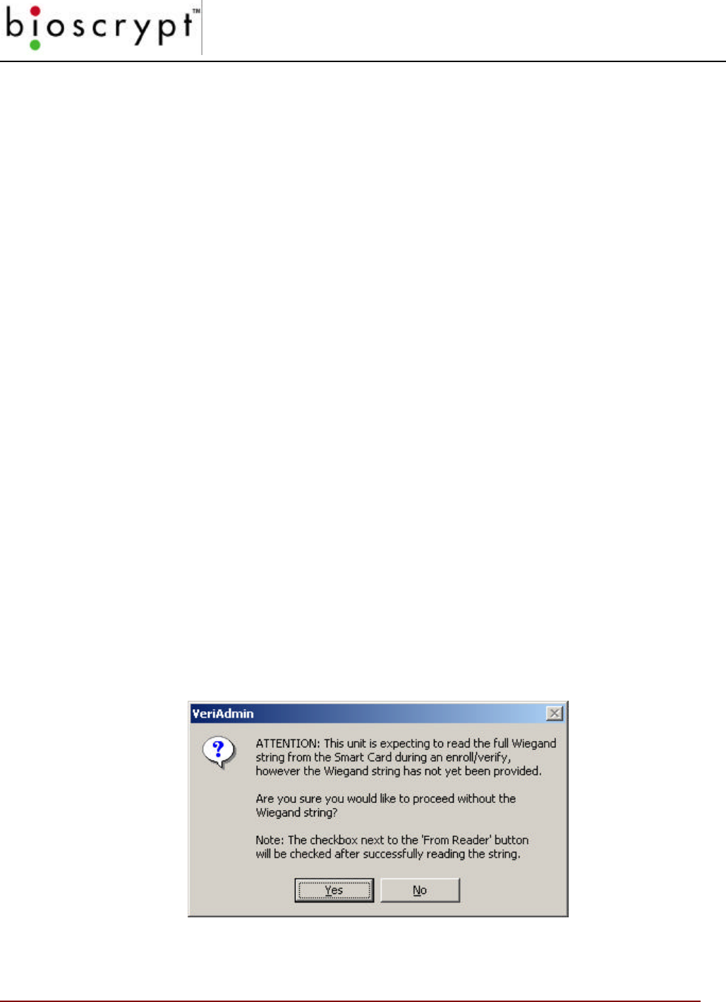
Version 4.2 (and above) of VeriAdmin includes a checkbox for READ/WRITE WIEGAND
STRING TO SMART CARD DURING ENROLL/VERIFY. This is a setting which tells the V-
Smart to attempt to read a Wiegand string from the Smart Card during a verify, and send
this Wiegand string out the Wiegand out lines if successful. This check box also means that
VeriAdmin will attempt to save the Wiegand string onto a Smart Card when enrolling. To do
so, it will require that a Wiegand string be read from an external Wiegand input device (the
FROM READER button during Quick or Advanced Enroll). Once you have read in the
Wiegand string, a check box (WIEGAND STRING READ) next to this button will be
checked. If VeriAdmin has not received the Wiegand string, the following dialog will be
displayed:

APPENDIX D – V-SMART OPERATIONS
101 © Copyright 2002, Bioscrypt Inc. All rights reserved.
Also, when you have this setting checked, VeriAdmin will remind you that it is saving the
Wiegand string when saving to a Smart Card. The WRITE WIEGAND STRING checkbox
below the “Save” button for Smart Cards will be checked.
As of VeriAdmin version 4.3, there is also the ability to delete Wiegand Strings associated
with a template. The DELETE WIEGAND STRING (1) button will prompt the user for a Site
Key and then delete the Wiegand string associated with the Primary Template. The
DELETE WIEGAND STRING (2) will perform the same task for the Secondary Template. It
is possible to use this function even if a Wiegand String has not been associated with a
template, so long as a “User Data” block has been placed in the Smart Card layout (see the
section on Smart Card Layout).
Also new to version 4.3 of VeriAdmin is the ability to secure and un-secure (Reset) smart
cards. The SECURE CARD button will secure a new smart card which has not been
updated with the proper Site Key (i.e., it still has the manufacturer’s default keys). You will
not need to enter the current Site Key to perform this function. Simply press this button and
present the card to the reader. Only the sectors of the smart card being used by the V-
Smart will be secured; all other sectors will remain untouched. Performing this function on a
smart card which has already been secured will have no effect, but is allowed. The RESET
CARD button will allow the user to un-secure a smart card (the reverse process) after
providing the proper Site Key. This will ERASE all V-Smart data on the card, including
templates, Wiegand Strings, and other user data, as defined in the smart card layout and
set the Site Key back to the original manufacturer’s default. This will essentially transform
the card back into a fresh, unused card, with the exception of those sectors not defined in
the layout (sectors used by another application, for example). Currently three
manufacturer’s settings are supported: Gem+ Flow A, Gem+ Flow B, and HID Flow B.
Please refer to the documentation provided by these manufacturers or from whom you
received your smart cards for more information.
At the top of the SMART CARD MANAGER dialog, you will see a radio button to select the
MAX TEMPLATES PER CARD. Currently, this can be set to either one or two templates,
although future cards with more memory may support additional templates. If two
templates option is selected, the Smart Card Layout must have two templates defined.
Otherwise when attempting to save a second template to the card, the user will receive an
“Invalid Smart Card Layout” error. If the maximum is set to only one template, attempting to
save a second template to a card will result in the error message “ESI – Storage Space is
FULL”. The ESI VERIFICATION TIMEOUT is a user definable setting which controls how
long the ESI will wait between verification from one card to the next. When a smart card is
presented, the ESI will read the template(s) and Wiegand data (if available), go into SLAVE
mode, and send the data to the main unit for verification with the live finger image. It will
then wait for a number of seconds (default is 15) before returning to HOST mode, where it
can accept a new card. This is the verification delay.
APPENDIX D – V-SMART OPERATIONS
102 © Copyright 2002, Bioscrypt Inc. All rights reserved.
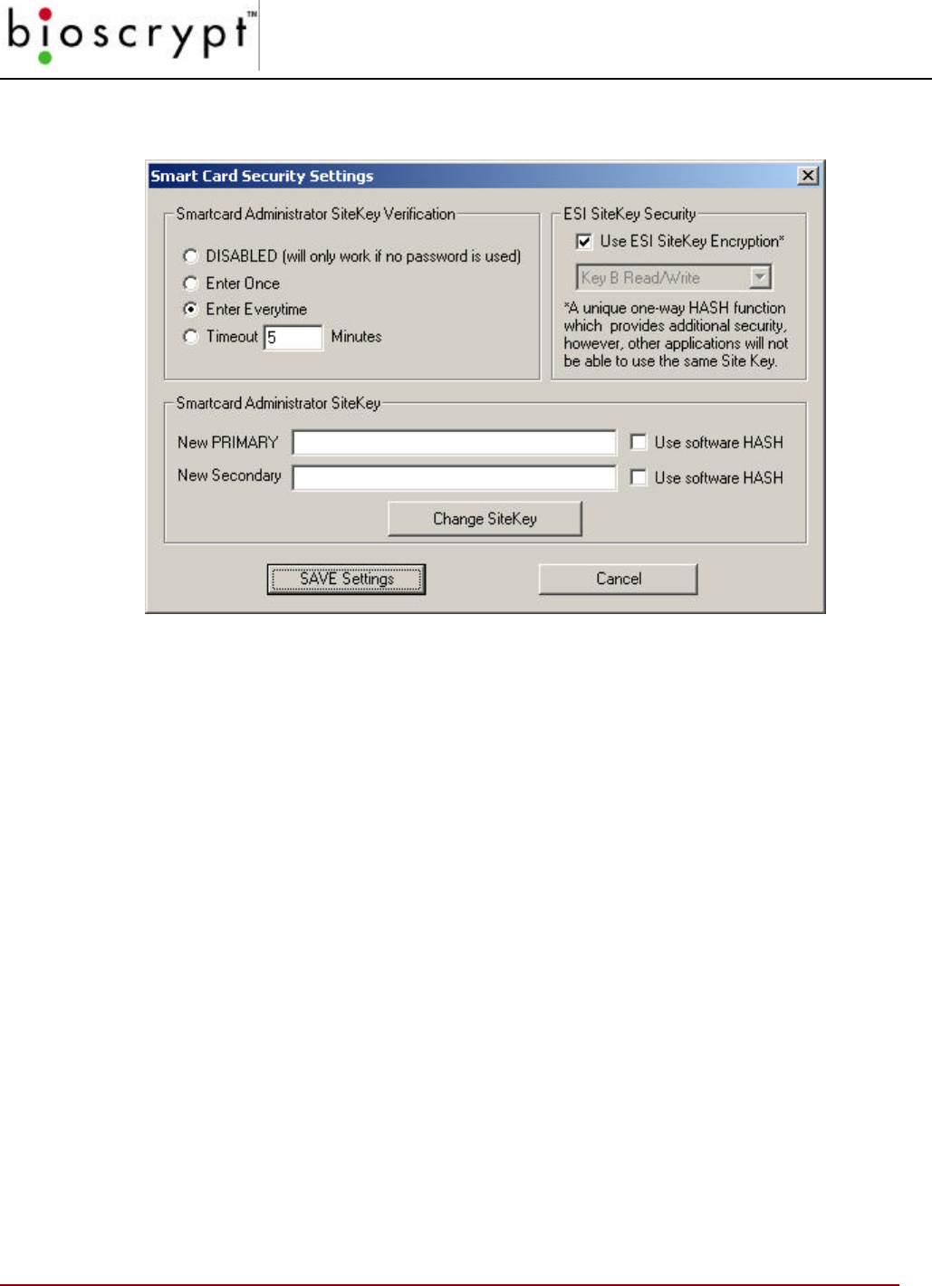
Pressing the SECURITY SETTINGS button will bring up the following dialog box:
This dialog will allow the user to adjust how often the Site Key verification is performed.
The default is EVERYTIME and VeriAdmin will reset to this default setting every time the
application is started. To change, select the desired choice and press the SAVE ADMIN
SETTINGS button. A Site Key verification is performed before the change is accepted.
This dialog also contains two checkboxes to enable the use of a 1-way hashing function on
the Site Key prior to sending to the V-Smart (Use software HASH). This is an extra
security step that will convert a simple text password to a 120-bit encrypted string every
time it is transmitted to the V-Smart. See Appendix E: Administrator SiteKey Management
for precautions related to changing Site Keys and using the hashing function.
The VeriAdmin Security Settings dialog box also allows the Administrator to change the
Primary and Secondary SiteKeys and to chose whether those new keys will be hashed or
not. Pressing the CHANGE SITEKEY button will always perform a Site Key Verification
before changing the current primary and secondary keys regardless of the timeout settings.
A new addition to this dialog is the ESI Site Key Security option. The checkbox USE ESI
SITEKEY ENCRYPTION is used in conjunction with the drop-down box. This deals with
how Site Keys are managed on the smart card itself and there are 3 available settings. The
default setting is use ESI Site Key Encryption with Key B for Read/Write. The other two
available options do not use ESI Site Key Encryption, and are provided for compatibility with
other applications which want to read and/or write data to the smart card. The checkbox
must be unchecked to enable these options. Note that Key A and Key B do not correspond
to PRIMARY and SECONDARY Site Keys; please read the manufacturer’s documentation
for more information. Only advanced users should change this setting!
APPENDIX D – V-SMART OPERATIONS
103 © Copyright 2002, Bioscrypt Inc. All rights reserved.
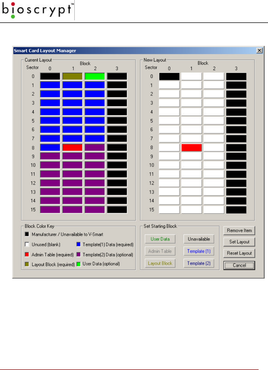
Pressing the CONFIGURE CARD LAYOUT button will bring up the Smart Card Manager
dialog box:
This dialog will allow the user to define a custom layout for all MIFARE compatible smart
cards.
Bioscrypt recommends that only advanced users attempt to configure the smart card
layout. Improper changes made to the layout may render the unit unusable with some
smart cards.
This section should be read completely before attempting to change the default layout provided
by Bioscrypt (as shown on the left above). The Smart Card Layout used by the V-Smart
consists of the following components: A layout block (brown), an Admin block (red), a PRIMARY
template (blue), a SECONDARY template (purple, optional), and User Data (green, optional).

APPENDIX D – V-SMART OPERATIONS
104 © Copyright 2002, Bioscrypt Inc. All rights reserved.
The Smart Card Layout Manager will NOT allow a user to configure a layout which is missing
the Admin block, the Layout Block, or a PRIMARY template. These are the minimum layout
components required to enable normal operation.
The memory structure for MIFARE compatible smart cards consists of 16 sectors (numbered 0
through 15) of 4 blocks each (numbered 0 through 3). Each block contains 16 bytes. The first
block at sector 0, block 0 contains manufacturer information and is not available. Also, the last
block of each sector contains Site Key and access information which secures that sector and is
thus unavailable for application data. Unavailable blocks are shown in VeriAdmin in black and
do not allow layout components to be placed there. This leaves 47 available blocks of 16 bytes
each, for a total of 752 available bytes. The Bioscrypt default layout contains space for two
templates and Wiegand information (stored in the green User Block) and will use all available
space. If space for non-Bioscrypt data is desired, include only the PRIMARY Template
(Template (1)) or do not include a User Block.
Place components on the layout on the right (under the “New Layout” section) by clicking one of
the buttons under the “Set Starting Block” section. You will then see flashing text which
instructs you to select one of the white, unused blocks above. Since the one-to-one templates
used by the V-Smart are 348 bytes, they will require 22 blocks of space (348 bytes / 16 bytes-
per-block = 22 blocks). All other layout components require a single block of space. You will
notice when placing a template on the layout that the blocks will wrap around whatever blocks
are in the way, consuming blocks from top to bottom. Templates may NOT wrap around from
bottom to top, and if there is insufficient space for a template, a warning will pop up and you will
not be able to place the template. If you would like to move a layout component or take if off of
the layout, you must remove it by first clicking on the Remove Item button and then clicking on
the item which is to be removed.
You will notice when you first enter the Smart Card Layout Manager that the Admin Block has
already been placed for you in sector 8, block 1. You may remove it and place it elsewhere,
however it is recommended that the Admin Block be left in this sector. The reason for this is
that the ESI will be able to read cards with a different layout than the one which is defined here
so long as the Admin Block is in this location. This allows for some flexibility with different card
layouts, however Bioscrypt still recommends that each site or facility use the same layout for
each card.
Layout Placement: It is recommended that the Admin Block be left in sector 8, block 1.
Bioscrypt recommends first placing the Layout Block, then the PRIMARY Template, and finally a
User Data block to hold the Wiegand Strings associated with each template. Note: If you do not
place at least ONE User Data block, VeriAdmin will be unable to read or write Wiegand String
data, and you will receive an error during enrollment. As of version 4.3, only TWO User Data
blocks may be placed on the layout. If two are placed, the first will be used for Wiegand data (if
used) and the second will be available for user data. These two blocks may be written to or
read using the Bioscrypt SDK, but not using VeriAdmin. When all other blocks have been
placed and there is sufficient space, place the SECONDARY template. You will not be able to
place Template (2) if you have placed two User Blocks because there will be insufficient space.
Finally, there is a convenient way to make the V-Smart layout wrap around sectors where non-

APPENDIX D – V-SMART OPERATIONS
105 © Copyright 2002, Bioscrypt Inc. All rights reserved.
Bioscrypt data is located (or is planned to go). Select the Unavailable Block button, then hold
down the SHIFT key to place multiple blocks. Do this before placing the other layout items so
that when they are placed they will automatically wrap around those blocks. Click Set Layout to
finalize the layout. You will need to provide the current Site Key. Upon successfully setting the
layout, the Smart Card Layout Manager will close, returning to the Smart Card Manager.
If at any time you would like to RESET the layout back to Bioscrypt defaults, click on the Reset
Layout button and provide the current Site Key. This will set the layout as shown in the screen
shot shown above.
There are some things to keep in mind when changing the Smart Card layout. First, note that
the number of templates defined on the layout should be greater than or equal to the Max
Templates per Card option. In other words, you should NOT define only one template and set
the maximum templates per card to TWO. This will result in an ESI Storage Full error upon
enrollment of a second template. Second, remember that changing the layout after some Smart
Cards have already been created with a different layout may cause those cards not to work
properly with the V-Smart. You will see a flashing or steady red LED on the unit when trying to
verify or you will receive an error in VeriAdmin indicating that the ESI cannot recognize the
layout. Third, it is important to realize that although you may write both Bioscrypt data and non-
Bioscrypt data to a Smart Card, each sector has its own Site Key which unlocks data on that
sector. Data may only be read from or written to a particular block if the proper Site Key for that
sector is provided. The ESI will use the same Site Key for all sectors being used by the V-
Smart, including sectors where only one or two blocks are actually being used. It is
recommended that any non-Bioscrypt data be placed on different sectors so that different keys
may be used for that data. Finally, keep in mind that if a third party application is used to
read/write any of the V-Smart data or the same Site Key is to be used for the entire card, the
ESI Site Key Encryption MUST use one of the un-hashed modes for compatibility. Please refer
to the documentation from the manufacturer from whom you have purchased your Smart Cards.
106 © Copyright 2002, Bioscrypt Inc. All rights reserved.
Section D.5 – Verification Using a Smart Card
After enrolling a template on a smart card, you can then use the card to perform a Verification.
Exit the SMART CARD MANAGER dialog so the V-SMART is placed back into HOST MODE.
Place the smart card near the reader as shown earlier in this section. The Top LED will
indicate:
In our example, the top LED should turn YELLOW, indicating “PLACE FINGER”. Remove the
card, place your finger and hold until the LED goes blank. Once the LED goes blank, you can
remove your finger. The LED will then either turn RED or GREEN indicating a FAIL or a PASS.
Best Performance Practices / Finger placement
The V-Smart unit should be mounted in a position that takes these factors into consideration:
ease of use, at a height that allows for proper finger placement, in line with other switch plates
or fixtures, and in accordance with Americans with Disabilities Act where applicable.
Recommended mounting height is 48-54” from floor to sensor level.
Typically, using either the index or middle finger provides the best performance. We
recommend you do NOT use thumbs or pinkies (little finger), but we do recommend that you
enroll an alternate finger on your other hand (total of 2 fingers enrolled). Please refer to
APPENDIX A for more details about maximize fingerprint performance
Indicator Meaning
RED Not Verified
GREEN Verified / Enrollment Accepted
Indicator Meaning
YELLOW Template READ; Place Finger on Sensor
RED No Template on smart card
FLASHING RED Invalid SiteKey, can not read card data

APPENDIX E – V-SMART ADMINISTRATOR
SITEKEY MANAGEMENT
107 © Copyright 2002, Bioscrypt Inc. All rights reserved.
Appendix E – V-Smart Administrator SiteKey Management
It is essential that the Administrator understand the use of V-Smart SiteKeys and handles
them appropriately. SiteKeys are the mechanism used by the V-Smart and the smart cards
to ensure that only authorized smart cards are used.
In this appendix, the following topics will be covered:
• What is a SiteKey?
• Why do I Need a SiteKey?
• What is the “Default” SiteKey?
• Where is the SiteKey Stored?
• What is the Difference Between PRIMARY and SECONDARY SiteKeys?
• How do I Initially Set a SiteKey for V-Smarts at My Installation?
• How do I Set the SiteKey on Individual Smart Cards?
• How do I Change the SiteKey if I Already Have a User Base of Previously
Created Smart Cards?
• What Happens if I FORGET My SiteKey?
• What Happens if Someone Else Learns My Installation’s SiteKey?
• What is the 1-Way Hashing Function Option in VeriAdmin for SiteKeys?
What is a SiteKey?
A SiteKey is a “password” used by VeriAdmin, the V-Smart and the smart cards. Each of
the 3 must use the same “password” to communicate and transfer information. If the
SiteKey stored in the V-Smart does not match the SiteKey used by the smart card, that V-
Smart will not be able to read or write to that smart card. By checking the SiteKey each
time, the V-Smart ensures that only authorized smart cards are used at a specific
installation. Similar to a computer logon password, if the smart card’s SiteKey does not
match the V-Smart’s SiteKey, that card will not be allowed to be used by that unit.
The V-Smart uses a maximum of 120-bits (15 characters) for the SiteKey.
Typically, the Administrator will set all V-Smart’s at a single installation to the same SiteKey.
Why do I Need a SiteKey?
Each installation must set their own SiteKey to distinguish their V-Smart smart cards from
every other installation of V-Smarts. If SiteKeys are not used, then any V-Smart would
accept smart cards created by any other V-Smart and a site’s installation could easily be
compromised. By using a unique SiteKey at each installation, you ensure that the only
smart cards that are accepted by V-Smarts are your site, are smart cards personally

APPENDIX E – V-SMART ADMINISTRATOR
SITEKEY MANAGEMENT
108 © Copyright 2002, Bioscrypt Inc. All rights reserved.
created at your site. It also ensures that data on the smart cards created at your site can
not be read by anyone that does not know your chosen SiteKey.
What is the “Default” SiteKey?
All V-Smarts are shipped from Bioscrypt with the SiteKey set to an empty string (120 bits of
all zeros). This allows Administrators to use the V-Smart in a non secure mode until they
are ready to set their personal SiteKey and secure the system. When using the Default
SiteKey in non secure mode and VeriAdmin performs a SiteKey Validation, simply do not
enter any key and just press the OK button. After the V-Smart verifies it is using the default
SiteKey and it verifies the smart card is also using the default SiteKey, the operation will be
performed.
Where is the SiteKey Stored?
The SiteKey is stored within the internal memory of the V-Smart and is encrypted and
stored on the smart card itself. The SiteKey is NOT stored within VeriAdmin, they are NOT
stored on the PC, and they can NOT be retrieved from the V-Smart. It is the
responsibility of the Administrator to remember the SiteKey and take measure to
prevent the SiteKey from being forgotten.
What is the Difference Between PRIMARY and SECONDARY
SiteKeys?
The V-Smart can store two SiteKeys. The PRIMARY SiteKey is used in normal operations
and is the SiteKey the Administrator used with performing a SiteKey verification operation
within VeriAdmin. The SECONDARY SiteKey is only used to update older cards when a
new PRIMARY SiteKey is set. See “How do I Change the SiteKey if I Already Have a
User Base of Previously Created Smart Cards?” for further details on how and when to
use the SECONDARY SiteKey.
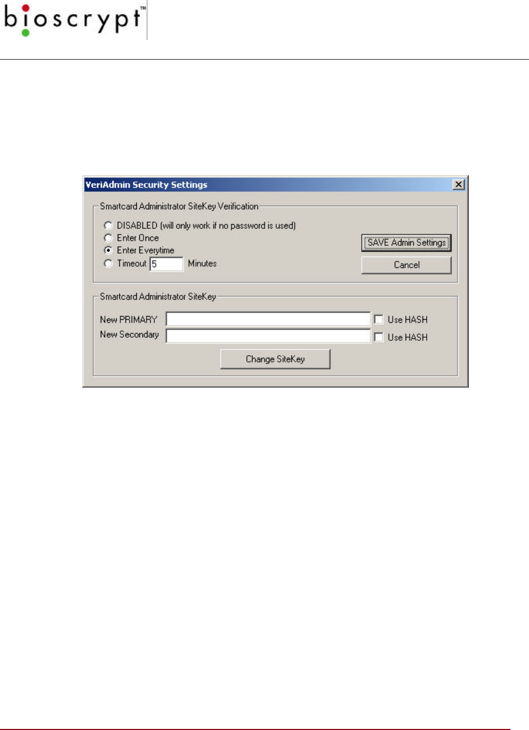
APPENDIX E – V-SMART ADMINISTRATOR
SITEKEY MANAGEMENT
109 © Copyright 2002, Bioscrypt Inc. All rights reserved.
How do I Initially Set a SiteKey for V-Smarts at My Installation?
You will need to set your installation’s SiteKey prior to creating secure user smart cards.
Once you become familiar with V-Smart operations and are comfortable enrolling users, you
should then chose your own SiteKey. The SMART CARD MANAGER section of VeriAdmin
allows the user to create and change SiteKeys.
1) Enter your desired SiteKey in the NEW PRIMARY box
2) Enter the previous SiteKey in the NEW SECONDARY box if you are changing
SiteKeys and you already have a user base of smart cards created with the previous
SiteKey and you want to update those cards to the NEW PRIMARY SiteKey. If there
is not a previous user base of cards that need updated, then enter a “-1” in the
Secondary box to turn off the auto SiteKey update function.
NOTE: DO NOT leave the NEW SECONDARY box blank unless you truly want to
update all Default SiteKey smart cards to the NEW PRIMARY SiteKey. This could
compromise security since any smart card created by any V-Smart using the Default
SiteKey would automatically be updated to the new Primary SiteKey
3) Press the CHANGE SITEKEY button
4) You will be presented the following Warning dialog box
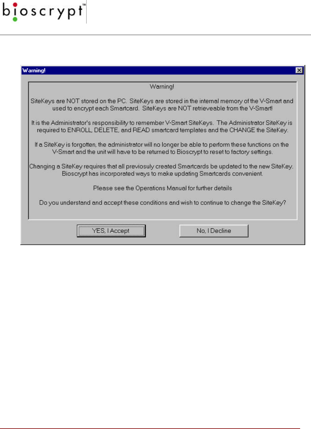
APPENDIX E – V-SMART ADMINISTRATOR
SITEKEY MANAGEMENT
110 © Copyright 2002, Bioscrypt Inc. All rights reserved.
5) Read the information carefully press the YES button if you accept.
6) You will be prompted to enter the CURRENT Primary SiteKey (this will be the Default
SiteKey if this is the first time you are changing the SiteKey)
7) If the CURRENT SiteKey entered is correct, you will be presented with a dialog box
indicating the changes were made.
8) Now all newly created smart cards from this specific V-Smart will use the NEW
PRIMARY SITEKEY and all older smart cards that use the defined SECONDARY
SITEKEY will be updated to the NEW PRIMARY the next time they are used by the
V-Smart.
9) You will need to set the same PRIMARY SITEKEY on all V-Smarts in your
installation in order for the smart cards to work at each V-Smart.

APPENDIX E – V-SMART ADMINISTRATOR
SITEKEY MANAGEMENT
111 © Copyright 2002, Bioscrypt Inc. All rights reserved.
How do I Set the SiteKey on Individual Smart Cards?
The V-Smart will attempt to set the SiteKey on the smart card during the enrollment
process.
• When an attempt is made to store a template on a smart card, the V-Smart will check
the key currently used by the Smart Card. If the V-Smart Primary SiteKey matches
the key on the smart card, the template is written.
• If the above fails, the V-Smart will check if its Secondary SiteKey matches the key on
the smart card. If they match, the key on the smart card is updated to the V-Smart’s
Primary SiteKey and the template is written (this adds ~0.5 seconds to the process).
• If both Primary and Secondary SiteKeys fail, the V-Smart will compare the smart card
key with the standard default MIFARE smart card key. If they match, the key on the
smart card is updated to the V-Smart’s Primary SiteKey and the template is written.
• If all of the above 3 fail, the V-Smart can not read or write to that smart card
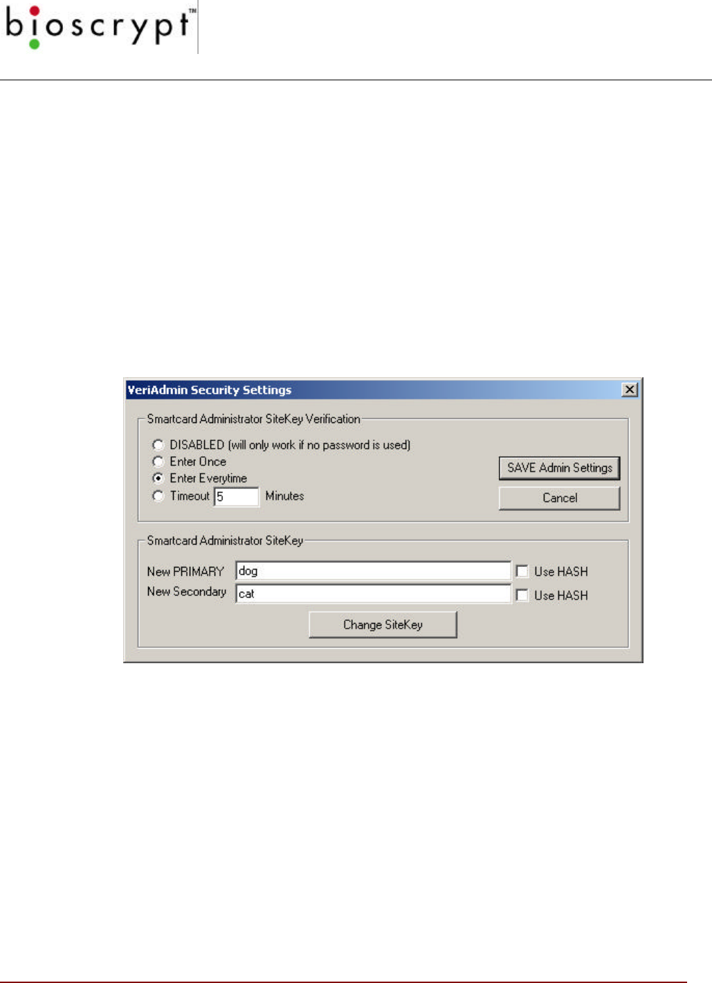
APPENDIX E – V-SMART ADMINISTRATOR
SITEKEY MANAGEMENT
112 © Copyright 2002, Bioscrypt Inc. All rights reserved.
How do I Change the SiteKey if I Already Have a User Base of
Previously Created V-Smart Smart Cards?
Let’s say you initially set the SiteKey during installation. For example, the Primary SiteKey
was set to “cat” and the Secondary was set to “-1” because you have no previous SiteKeys
to update. You then enrolled 100 users and created 100 smart cards. The smart card key
on each of those cards would be “cat”.
Now you want to change the password because the SiteKey of “cat” was compromised
when non-authorized personnel where told the SiteKey and the installation is no longer
completely secure. Let’s say you want to change the SiteKey from “cat” to “dog”.
• In the Smart Card Security Settings window, enter “dog” as the New PRIMARY and
enter “cat” as the New SECONDARY
• Press the CHANGE SITEKEY button and you will again be presented with the
warning that you need to always remember the SiteKey.
• After pressing the ACCEPT button, you will be prompted for the CURRENT
PRIMARY SiteKey. Enter “cat” since that is the currently stored SiteKey on the V-
Smart.
• You should then be presented with a dialog indicating the SiteKey was changed.
Typically, you will need to repeat this “change” process on all V-Smarts at your
installation.
• At this point, all previously created smart cards still contain the previous key of “cat”.
However, when a smart card is presented to the V-Smart it will follow the following
steps:
1. When a card is presented and the V-Smart tries to read the data from the card,
the V-Smart will check the key currently used by the Smart Card. Since the
key on the card is “cat” and the V-Smart Primary key is now “dog”, this key
check will fail.

APPENDIX E – V-SMART ADMINISTRATOR
SITEKEY MANAGEMENT
113 © Copyright 2002, Bioscrypt Inc. All rights reserved.
2. Next, the V-Smart will check if its Secondary SiteKey matches the key on the
smart card. In our example, they do match so the key on the smart card is
changed (updated) to the V-Smart’s Primary SiteKey. This “update” adds ~0.5
seconds to the process, but only happens the first time the older card is
presented. After that, the new Primary is already on the smart card step #1
above will PASS from now on.
If neither the Primary nor the Secondary SiteKey on the V-Smart matches the smart
card’s key, the V-Smart will not be able to use that card. You must use the previous
SiteKey as the SECONDARY SiteKey or all previously created smart cards will be
unusable.
Once the entire user base of cards has been updated to the NEW PRIMARY SiteKey,
you should once again perform the “change SiteKey process”. This time keep the
primary SiteKey the same, but enter a “-1” for the Secondary SiteKey. This will disable
the ‘auto update’ feature and any remaining smart cards with “cat” on them will no longer
work.
What Happens if I FORGET My SiteKey?
DO NOT LET THIS HAPPEN! If an Administrator forgets the Primary SiteKey then all
previously created smart cards will continue to work, but the following will happen:
• They can no longer create new smart cards
• They will not be able to READ templates from current smart cards
• They will not be able to CHANGE the SiteKey on the V-Smarts
• The V-Smarts will have to be returned to Bioscrypt for reprogramming and once
reprogrammed, the previously enrolled smart cards will no longer be usable.
What Happens if Someone Else Learns My Installation’s
SiteKey?
SiteKeys need to be protected just like computer passwords and should not be told to
unauthorized personnel. In the event that the SiteKey has been compromised, follow the
steps defined in the previous “How do I Change the SiteKey if I Already Have a User
Base of Previously Created Smart Cards?” section to change the SiteKey and
automatically update all user base smart cards.

APPENDIX E – V-SMART ADMINISTRATOR
SITEKEY MANAGEMENT
114 © Copyright 2002, Bioscrypt Inc. All rights reserved.
What is the 1-Way Hashing Function Option In VeriAdmin for
SiteKeys?
VeriAdmin allows Administrators to add additional security by optionally performing a 1-
way Hash function on entered SiteKeys. This is DIFFERENT from the ESI SiteKey
Encryption option. This function will take the user-entered password and create an
encrypted 120-bit SiteKey from that password. This encrypted version is then used as
the SiteKey for the V-Smart and smart cards in place of the user-defined password. In
extreme cases, this can make it more difficult for criminals to “sniff” internal networks
and capture passwords during serial communications. DO NOT USE THIS OPTION IF
YOU INTEND TO SHARE SMART CARD DATA WITH OTHER APPLICATIONS!
To the Administrator, this all happens behind the scenes and you never have to
remember anything other then the simple password. You just have to make sure that if
you set a NEW SiteKey with the HASH checkbox selected, then afterwards you need to
also check the “Hash the CURRENT SiteKey” so that each time the SiteKey Verification
process happens, a hashed current SiteKey will be compared with the stored hashed
Primary SiteKey.
The HASH function check box is ignored if the SiteKey textbox is empty (for non secure
V-Smart default key use), or if “-1” is entered the SECONDARY SiteKey text box (for
turning OFF the auto update feature).
PLEASE NOTE:
The HASH function check box has been moved from the Security Settings
Dialog to the Site Key Dialog for VeriAdmin v4.10. Each time the Site Key is
entered, the check box determines whether to HASH the key for the Current Key.

115 © Copyright 2002, Bioscrypt Inc. All rights reserved.
Bioscrypt Contact Information
Technical Support Contact Information:
Telephone : 1-888-982-4643 (toll free)
1-818-501-3908
Email: support@bioscrypt.com
Address Bioscrypt Inc
Technical Support Dept
5000 Van Nuys Blvd, Suite 300
Sherman Oaks, CA, 91403
Corporate & Canadian Office
5450 Explorer Drive, Suite 500
Mississauga, ON, Canada L4W
5M1
T 905 624 7700
F 905 624 7742
www.bioscrypt.com
U.S. Office
5000 Van Nuys Blvd.,
Suite 300
Sherman Oaks, CA 91403
U.S.A.
T 818 501 3908
F 818 461-0843
support@bioscrypt.com