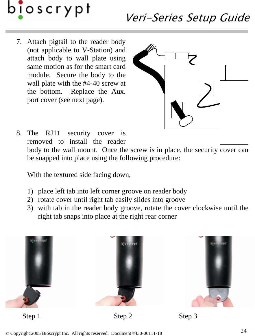
Bioscrypt VSMRTAHR V-Smart, A, H, R RFID Reader User Manual Veri Series Setup Guide
Bioscrypt, Inc. V-Smart, A, H, R RFID Reader Veri Series Setup Guide
UserManual.wiki
>
Bioscrypt
>
VSMRTAHR User Manual
users manual
Navigation menu
Upload a User Manual
Namespaces
Wiki Guide
HTML
PDF
Info
Views
User Manual
Discussion / Help
Navigation


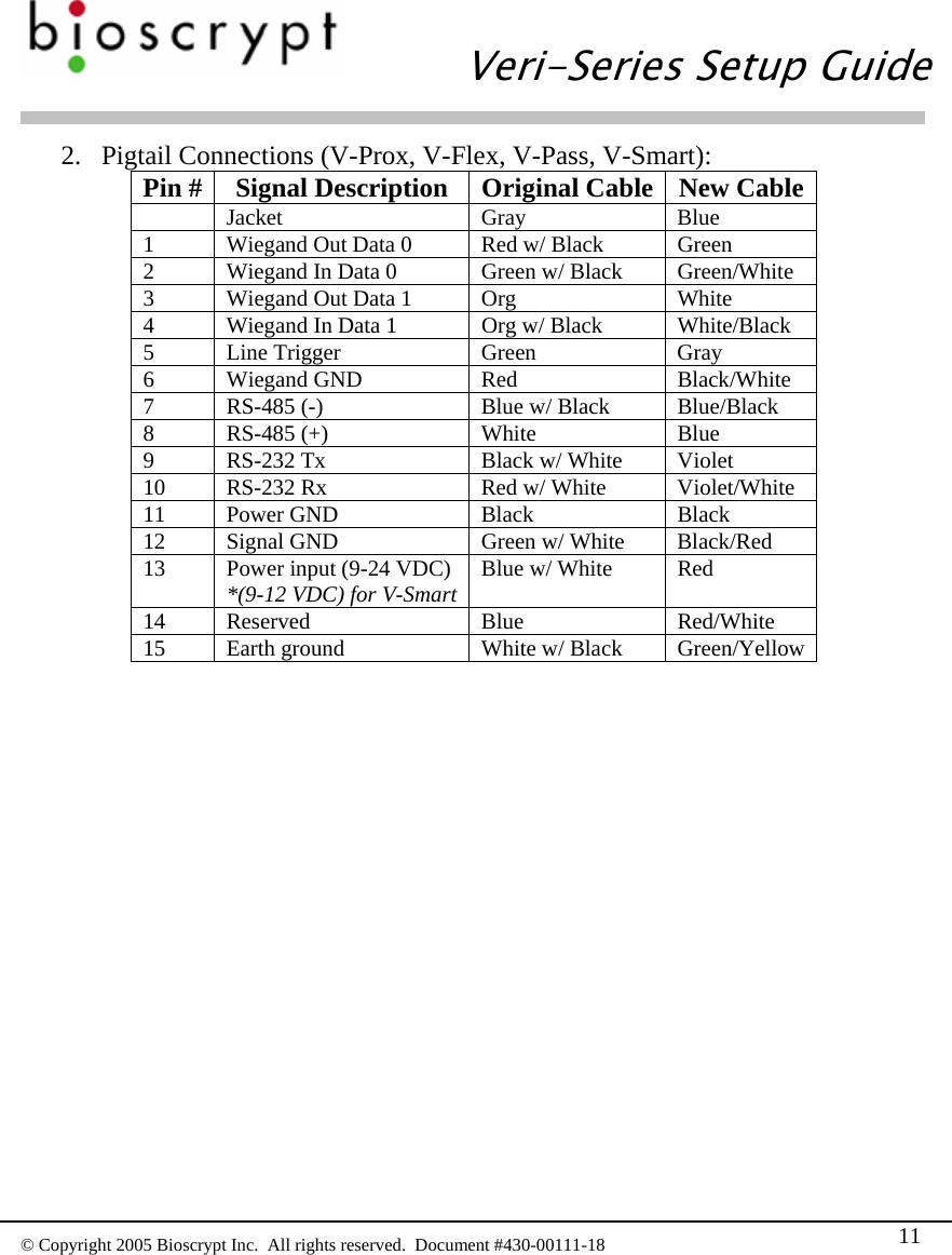
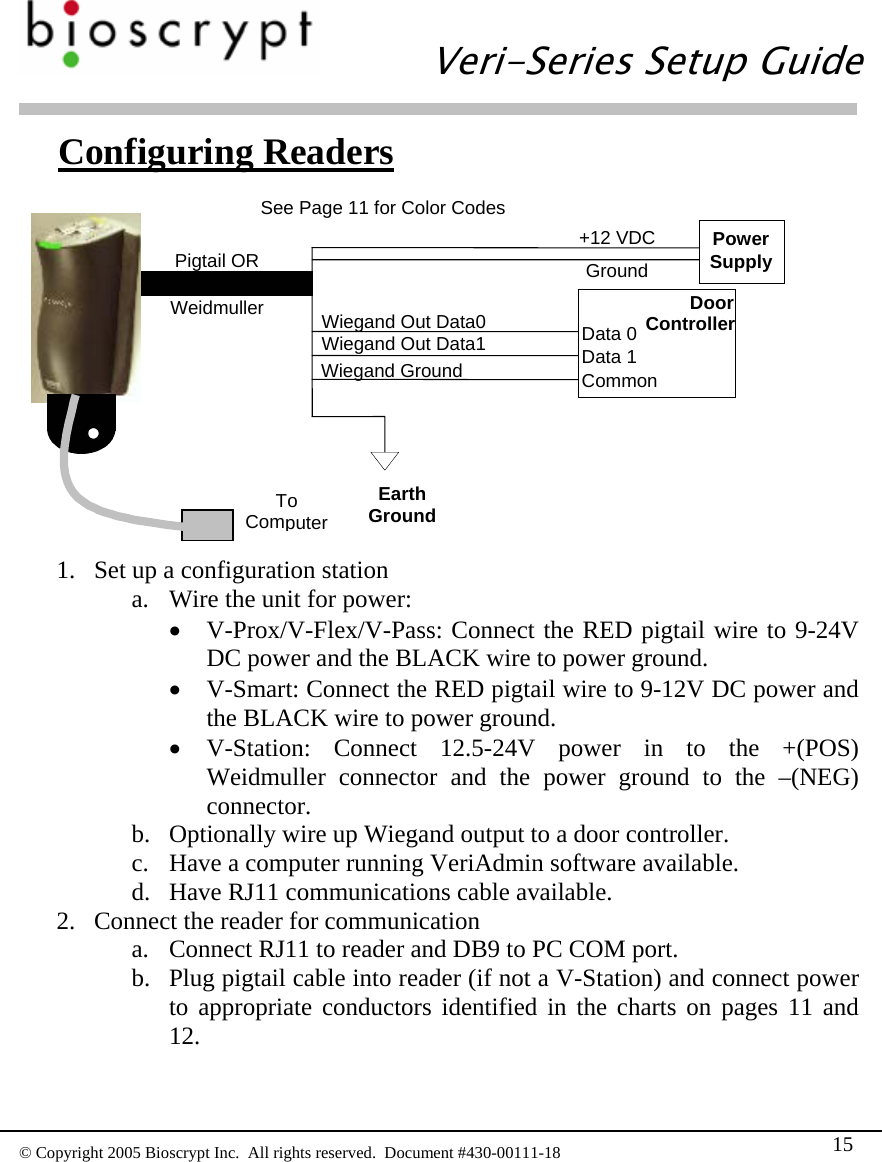
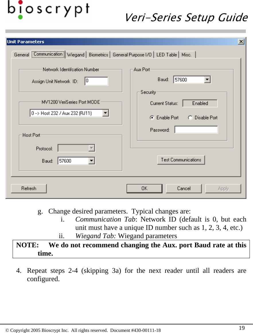
![Veri-Series Setup Guide © Copyright 2005 Bioscrypt Inc. All rights reserved. Document #430-00111-18 12 3. Weidmuller Connections (V-Station only): Group Label Signal Description RS-485 TX(+) Transmit + TX(-) Transmit - RX(+) Receive + RX(-) Receive - GND RS-485 Ground RS-232 GND RS-232 Ground TX Transmit RX Receive Power/Ground +(POS) 12.5 - 24 VDC + -(NEG) 12.5 - 24 VDC - EGND Earth Ground Wiegand IN 0 Data 0 In IN 1 Data 1 In OUT 0 Data 0 Out OUT 1 Data 1 In LED IN LED In LED OUT LED Out GND Wiegand Ground TTL (IN) IN 0 TTL Data 0 In IN 1 TTL Data 1 In TTL (OUT) OUT 0 H TTL Data 0 Out OUT 1 L TTL Data 1 Out GND TTL Ground 4. [RS-485 network only]: Use a daisy chain network design as depicted in the following figure. Do not use a star or other multi-drop configuration.](https://usermanual.wiki/Bioscrypt/VSMRTAHR/User-Guide-693243-Page-41.png)
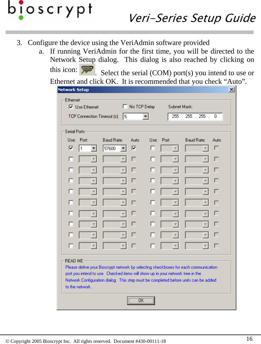
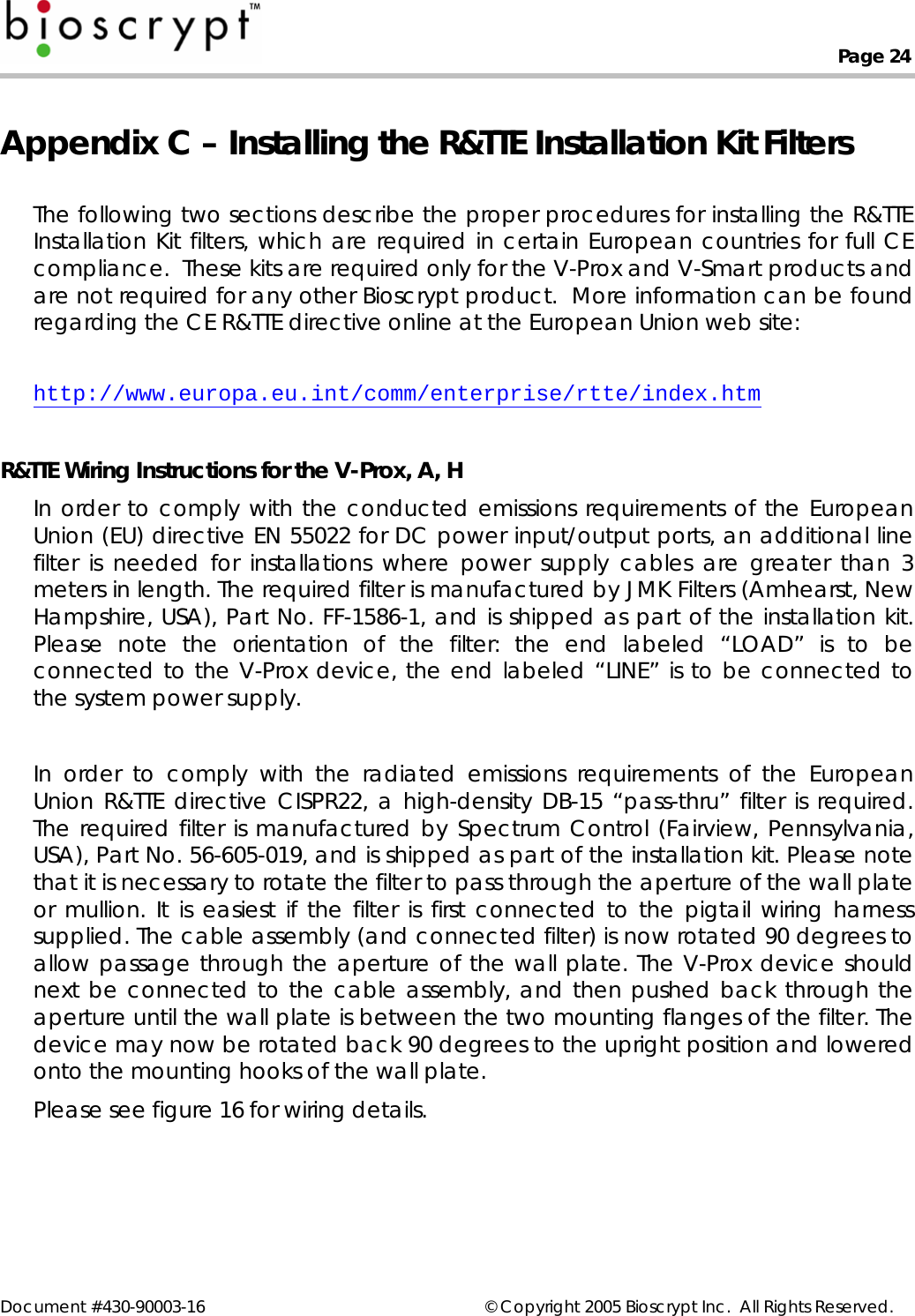
![Veri-Series Setup Guide © Copyright 2005 Bioscrypt Inc. All rights reserved. Document #430-00111-18 13 Use one pair (e.g. blue/white and white/blue) for RS-485 connections. Connect readers identically at each reader (e.g. blue/white on Cat5 to RS-485 (-) on pigtail/Weidmuller Connector and white/blue on Cat5 to RS-485 (+) on pigtail/Weidmuller Connector). Power Supply Unit Unit Unit Unit 3Data0 Data1 Wiegand Gnd. 2RS-232 /RS-485 Converter Cat5 Twisted Pair Computer Door Controller 5. [RS-485 network only]: At converter, jumper TD(A) with RD(A) and TD(B) with RD(B). Connect Blue/white from Cat5 to either of A terminals and White/blue from Cat5 to either of B terminals. Make certain to connect power correctly. RS-232TD(A)TD(B)RD(A)RD(B)+12VDCGNDTwisted Pair. Use Cat5 rated cable RS-485 (+)RS-485 (-)Connect to Earth Ground 6. [RS-485 network only]: RS-485 supports distances up to 4,000 feet (1,200 meters) and/or 31 readers. To extend these limitations, contact Bioscrypt Technical Support. Typically no end-of-line termination is required unless the total run exceeds 2,000 feet. 7. [RS-485 network only]: Set up network using 9600 baud rate. Only increase this data rate after the system is operating properly at 9600.](https://usermanual.wiki/Bioscrypt/VSMRTAHR/User-Guide-693243-Page-42.png)
![Veri-Series Setup Guide © Copyright 2005 Bioscrypt Inc. All rights reserved. Document #430-00111-18 14 8. [Ethernet network only]: Typically a star network topology is used with a network switch or hub, but a bus topology may be used. Be sure to connect all devices using straight-thru (as apposed to cross-over) cables. The exception to this is when connecting a single device directly to the computer Ethernet adaptor. 9. [Ethernet network only]: Up to 254 readers can reside on a single Ethernet bus, although repeaters may be required to boost the signal over longer distances. The V-Station supports 10base-T Ethernet (10 Mbps)*. A 10 Mbps Ethernet network supports distances up to 100 meters (328 ft.) between readers (2,500m with repeaters). Bioscrypt recommends isolating your network of readers from computers (other than the admin PC) and other devices to maximize security. A firewall is highly recommended if the network will include other devices or PCs. For obvious reasons, it is not a good idea to expose your network of readers to the outside world (i.e., the Internet). *Ethernet communication is supported in firmware versions 7.10 and higher. VeriAdmin 5.10 or higher is required for administration over Ethernet.](https://usermanual.wiki/Bioscrypt/VSMRTAHR/User-Guide-693243-Page-43.png)