Bioscrypt VSMRTAHR V-Smart, A, H, R RFID Reader User Manual Veri Series Setup Guide
Bioscrypt, Inc. V-Smart, A, H, R RFID Reader Veri Series Setup Guide
users manual

Page 1
Document #430-90003-16 © Copyright 2005 Bioscrypt Inc. All Rights Reserved.
Appendix A – Notices
The Veri-Series product line has been tested for compliance with all applicable
international standards. The resulting approvals are listed below, and are
additionally printed on the labeling located on the rear panel of the product.
The power supply offered by Bioscrypt is CE and CSA approved and UL listed.
V-Flex FCC, UL 294, CSA, CE
V-Prox FCC, UL 294, CSA, CE
V-Pass FCC, UL 294, CSA, CE
V-Smart FCC, UL 294, CSA, CE
V-Station FCC, UL 294, CSA, CE
FCC Information to Users
This equipment has been tested and found to comply with the limits for a Class A
digital device, pursuant to Part 15 of the FCC Rules. These limits are designed to
provide reasonable protection against harmful interference when the equipment
is operated in a commercial environment. This equipment generates, uses, and
can radiate radio frequency energy and, if not installed and used in accordance
with the instruction manual, may cause harmful interference to radio
communications. Operation of this equipment in a residential area is likely to
cause harmful interference in which case the user will be required to correct the
interference at his own expense.
FCC Class B Digital Device or Peripheral - User’s Notice (for all V-Station models only)
This equipment has been tested and found to comply with the limits for a Class B
digital device, pursuant to Part 15 of the FCC Rules. These limits are designed to
provide reasonable protection against harmful interference in a residential
installation. This equipment generates, uses, and can radiate radio frequency
energy and, if not installed and used in accordance with the instruction manual,
may cause harmful interference to radio communications. However, there is no
guarantee that interference will not occur in a particular installation. If this
equipment does cause harmful interference to radio or television reception, which
can be determined by turning the equipment off and on, the user is encouraged
to try to correct the interference by one of more of the following measures:
• Reorient or relocate the receiving antenna

Page 2
Document #430-90003-16 © Copyright 2005 Bioscrypt Inc. All Rights Reserved.
• Increase the separation between the equipment and receiver
• Connect the equipment into an outlet on a circuit different from that to which
the receiver is connected
• Consult the dealer or an experienced radio/TV technician for help
CE Information to Users
All Veri-Series devices have the CE mark, for compliance with CISPR22 /EN 55022
requirements. For European Union (EU) countries, V-Prox, V-Smart, and V-Station
(models V-Station A, P, V-Station A, G, and V-Station A, H) are compliant with CE
under the R&TTE Directive, related to the radio transceivers that are part of their
design. More information can be found regarding the CE R&TTE directive online
at the European Union web site:
http://www.europa.eu.int/comm/enterprise/rtte/index.htm
The V-Prox and V-Smart are compliant with this directive if, and only if, the user
installs the Bioscrypt specified R&TTE Installation Kit (Bioscrypt part number 832-
00103-00). This filter kit should be included with any V-Prox or V-Smart product if it
was shipped to a country within the EU.
The R&TTE Installation Kit consists of two filters: a line filter used to minimize
conducted emissions from power supply lead lengths greater than 3 meters and a
DB-15 “Pass-Thru” filter used to minimize radiated emissions.
Line Filter: Manufacturer: JMK Filters
Amhearst, New Hampshire
USA, 03031
www.JMKFilters.com
Part Number: FF-1586-1
Pass-Thru Filter: Manufacturer: Spectrum Control
Fairview, Pennsylvania
USA, 16415
www.SpectrumControl.com
Part Number: 56-605-019

Page 3
Document #430-90003-16 © Copyright 2005 Bioscrypt Inc. All Rights Reserved.
If the filters were not included with the product or if they are desired separately,
they may be ordered from Bioscrypt (part number 832-00103-00) or the distributor
from which the product was purchased. Please see Appendix C for details on
proper installation of these filters.
NOTE: The installation of these filters is mandatory for the registered CE mark, and
associated R&TTE directive compliance to be valid within the European Union.
Failure to do so will render the CE mark and consequent right to operate the
equipment null and void.
Warning to Users
Warning: Changes or modifications not expressly approved by Bioscrypt Inc.
could void the user’s authority to operate the equipment.
V-Prox, A, H Information for Users*
The V-Prox, A, H includes a HID contact-less proximity reader. This device has the
following characteristics:
Transmit Frequency: 125 KHz
Excite Frequency: 125 KHz
V-Smart, A Information for Users
The V-Smart, A includes a contact-less smart card reader (GemEasyLink680SL). This
is a radio-transceiver with the following characteristics:
Operating Frequency Range: 13.553-13.567 MHz
RF Power Rating: 0.0 Watts
RF Output Impedance: 50 Ohms
V-Smart, A, H Information for Users
The V-Smart, A, H includes a contact-less smart card reader (HID iCLASS™ OEM
100/RS232). This is a radio-transceiver with the following characteristics:
Operating Frequency Range: 13.553-13.567 MHz
RF Power Rating: 0.0 Watts
RF Output Impedance: 50 Ohms

Page 4
Document #430-90003-16 © Copyright 2005 Bioscrypt Inc. All Rights Reserved.
V-Station, A, G Information for Users
The V-Station, A, G includes a contact-less smart card reader (GemEasyLink680SL).
This is a radio-transceiver with the following characteristics:
Operating Frequency Range: 13.553-13.567 MHz
RF Power Rating: 0.0 Watts
RF Output Impedance: 50 Ohms
V-Station, A, H Information for Users
The V-Station, A, H includes a contact-less smart card reader (HID iCLASS™ OEM
100/RS232). This is a radio-transceiver with the following characteristics:
Operating Frequency Range: 13.553-13.567 MHz
RF Power Rating: 0.0 Watts
RF Output Impedance: 50 Ohms
V-Station, A, P Information for Users*
The V-Station, A, P includes a HID contact-less proximity reader. This device has
the following characteristics:
Transmit Frequency: 125 KHz
Excite Frequency: 125 KHz
*Warning to Users
Within the European Community, use of the 125 kHz band is not
harmonized. Therefore this product requires notification to the National
Regulatory Body and requires product registration for a particular
country. If you intend to move this device within the EU, please contact your
distributor first in order to check if this device is approved for use in that particular
country.

Page 5
Document #430-90003-16 © Copyright 2005 Bioscrypt Inc. All Rights Reserved.
Appendix B – European Certification Documentation
This appendix contains data related to the Veri-Series product line regarding the
test procedures and Declarations of Conformity as required under the R&TTE
directive by the European Union for all devices containing radio transmitters. The
following Bioscrypt products contain radio transmitters:
Name Model Number
V-Prox V-Prox, A, H
V-Smart / MIFARE V-Smart, A
V-Smart / iCLASS V-Smart, A, H
V-Station / Prox V-Station, A, P
V-Station / MIFARE V-Station, A, G
V-Station / iCLASS V-Station, A, H
Hereby, Bioscrypt, declares that the V-Prox, V-Smart/MIFARE, and V-Smart/iCLASS
are in compliance with the essential requirements and other relevant provisions of
Directive 1999/5/EC.
Restrictions of Use
Bioscrypt has notified the following EU countries and gained approval to sell the -
Prox, V-Smart/MIFARE, and V-Smart/iCLASS products:
• Belgium
• France
• Germany
• Nederland
• Spain
There are no restrictions of use for any of these products within those countries.
V-Station/Prox, V-Station/MIFARE, and V-Station/iCLASS individual country
approval is pending. For latest product approval status and updates, please refer
to the Bioscrypt web page at:
http://www.bioscrypt.com
Declaration of Conformity
For each product, Declarations of Conformity are listed on the following pages for:
• R&TTE Directive 1999/5/EC
• EMC Directive 89/336/EEC
• Low Voltage Safety Directive 73/23/EEC
Page 6
Document #430-90003-16 © Copyright 2005 Bioscrypt Inc. All Rights Reserved.
DECLARATION OF CONFORMITY
FOR THE R&TTE DIRECTIVE 1999/5/EC
Manufacturer’s Name/Address: Bioscrypt Inc.
Address: 505 Cochrane Drive
Markham Ontario
Canada, L3R 8E3
Contact Person: Mr. Shiraz Kapadia, Vice President of Operations
Phone #: 905-940-7784
Fax #: 905-940-7642
Email Address: shiraz.kapadia@bioscrypt.com
Equipment Type: Radio Communications Equipment
Product Name: V-Prox, A
Model No.: V-Prox, A, H
RF Output Power: -6.9 dBuA/m 10 meters
Transmitter Operating Frequency
Range:
125 kHz
Emission Designation: 5K7N0N
Duty Cycle: 18.8%
Year of manufacture: 2003
Country Of Manufacture: Canada
The above product has been
tested by UltraTech Engineering
Labs Inc., and found to comply
with:
European Telecommunications Standards Institute (ETSI)
EN 300 330-1 V1.3.1 (2001-06) & EN 300 330-2 V1.1.1 (2001-06)
Radio Equipment and Systems; Short Range Devices (SRD);
Technical Characteristics and Test Methods for Radio Equipment
in the Frequency Range 9 kHz to 25 MHz and Inductive Loop
Systems in the Frequency Range 9 kHz to 30 MHz, Parts 1 and 2.
Test Laboratories: UltraTech EMC Labs Inc.
3000 Bristol Circle
Oakville, Ontario, Canada, L6H 6G4
I, the undersigned, hereby declare that the equipment as tested is representative within manufacturing tolerance to un
i
Manufacturer Legal Representative in Europe
Shiraz Kapadia Neil McDonald
Vice President, Operations Director of Sales, EMEA
Markham, ON, Canada High Wycombe, England
September 9, 2003 November 25, 2002
Page 7
Document #430-90003-16 © Copyright 2005 Bioscrypt Inc. All Rights Reserved.
DECLARATION OF CONFORMITY
FOR THE EMC DIRECTIVE 89/336/EEC
Manufacturer’s Name/Address: Bioscrypt Inc.
Address: 505 Cochrane Drive
Markham Ontario
Canada, L3R 8E3
Contact Person: Mr. Shiraz Kapadia, Vice President of Operations
Phone #: 905-940-7784
Fax #: 905-940-7642
Email Address: shiraz.kapadia@bioscrypt.com
Equipment Type: Radio Communications Equipment
Product Name: V-Prox, A
Model No.: V-Prox, A, H
RF Output Power: -6.9 dBuA/m 10 meters
Transmitter Operating Frequency
Range:
125 kHz
Emission Designation: 5K7N0N
Duty Cycle: 18.8%
Year of manufacture: 2003
Country Of Manufacture: Canada
The above product has been
tested by
UltraTech Engineering Labs Inc.,
and found to comply with:
European Telecommunications Standards
Institute (ETSI)
EN 301 489-1 V1.4.1 (2002-04) & EN 301 489-3 V1.4.1 (2002-08) –
Electromagnetic Compatibility and Spectrum Matters (ERM);
Electromagnetic Compatibility (EMC) Standard for Radio Equipment
and Services, Parts 1 and 3.
Test Laboratories: UltraTech EMC Labs Inc.
3000 Bristol Circle
Oakville, Ontario, Canada, L6H 6G4
I, the undersigned, hereby declare that the equipment as tested is representative within manufacturing tolerance to units
.
Manufacturer Legal Representative in Europe
Shiraz Kapadia Neil McDonald
Vice President, Operations Director of Sales, EMEA
Markham, ON, Canada High Wycombe, England
September 9, 2003 November 25, 2002
Page 8
Document #430-90003-16 © Copyright 2005 Bioscrypt Inc. All Rights Reserved.
DECLARATION OF CONFORMITY
FOR THE LOW VOLTAGE SAFETY DIRECTIVE 73/23/EEC
Manufacturer’s Name/Address: Bioscrypt Inc.
Address: 505 Cochrane Drive
Markham Ontario
Canada, L3R 8E3
Contact Person: Mr. Shiraz Kapadia, Vice President of Operations
Phone #: 905-940-7784
Fax #: 905-940-7642
Email Address: shiraz.kapadia@bioscrypt.com
Equipment Type: Radio Communications Equipment
Product Name: V-Prox, A
Model No.: V-Prox, A, H
RF Output Power: -6.9 dBuA/m 10 meters
Transmitter Operating Frequency
Range:
125 kHz
Emission Designation: 5K7N0N
Duty Cycle: 18.8%
Year of manufacture: 2003
Country Of Manufacture: Canada
The above product has been
tested by
UltraTech Engineering Labs Inc.,
and found to comply with:
EN 60215:1996 +A1:1996 - Safety Requirements for Radio
Transmitting Equipment
Test Laboratories: UltraTech EMC Labs Inc.
3000 Bristol Circle
Oakville, Ontario, Canada, L6H 6G4
I, the undersigned, hereby declare that the equipment as tested is representative within manufacturing tolerance to units
.
Manufacturer Legal Representative in Europe
Shiraz Kapadia Neil McDonald
Vice President, Operations Director of Sales, EMEA
Markham, ON, Canada High Wycombe, England
September 9, 2003 November 25, 2002

Page 9
Document #430-90003-16 © Copyright 2005 Bioscrypt Inc. All Rights Reserved.
DECLARATION OF CONFORMITY
FOR THE R&TTE DIRECTIVE 1999/5/EC
Manufacturer’s Name/Address: Bioscrypt Inc.
Address: 505 Cochrane Drive
Markham Ontario
Canada, L3R 8E3
Contact Person: Mr. Shiraz Kapadia, Vice President of Operations
Phone #: 905-940-7784
Fax #: 905-940-7642
Email Address: shiraz.kapadia@bioscrypt.com
Equipment Type: Radio Communications Equipment
Product Name: V-Smart
Model No.: V-Smart, A
RF Output Power: -19.3 dBuA/m 10 meters
Transmitter & Receiver Operating
Frequency Range:
13.553-13.567 MHz
Emission Designation: 3K0D1D
Duty Cycle: 100%
Year of manufacture: 2003
Country Of Manufacture: Canada
The above product has been
tested by UltraTech Engineering
Labs Inc.,
and found to comply with:
European Telecommunications Standards Institute (ETSI)
EN 300 330-1 V1.3.1 (2001-06) & EN 300 330-2 V1.1.1 (2001-06)
Radio Equipment and Systems; Short Range Devices (SRD);
Technical Characteristics and Test Methods for Radio Equipment
in the Frequency Range 9 kHz to 25 MHz and Inductive Loop
Systems in the Frequency Range 9 kHz to 30 MHz, Parts 1 and 2.
Test Laboratories: UltraTech EMC Labs Inc.
3000 Bristol Circle
Oakville, Ontario, Canada, L6H 6G4
I, the undersigned, hereby declare that the equipment as tested is representative within manufacturing tolerance to units.
Manufacturer Legal Representative in Europe
Shiraz Kapadia Neil McDonald
Vice President, Operations Director of Sales, EMEA
Markham, ON, Canada High Wycombe, England
September 9, 2003 November 25, 2002

Page 10
Document #430-90003-16 © Copyright 2005 Bioscrypt Inc. All Rights Reserved.
DECLARATION OF CONFORMITY
FOR THE EMC DIRECTIVE 89/336/EEC
Manufacturer’s Name/Address: Bioscrypt Inc.
Address: 505 Cochrane Drive
Markham Ontario
Canada, L3R 8E3
Contact Person: Mr. Shiraz Kapadia, Vice President of Operations
Phone #: 905-940-7784
Fax #: 905-940-7642
Email Address: shiraz.kapadia@bioscrypt.com
Equipment Type: Radio Communications Equipment
Product Name: V-Smart
Model No.: V-Smart, A
RF Output Power: -19.3 dBuA/m 10 meters
Transmitter & Receiver Operating
Frequency Range:
13.553-13.567 MHz
Emission Designation: 3K0D1D
Duty Cycle: 100%
Year of manufacture: 2003
Country Of Manufacture: Canada
The above product has been
tested by
UltraTech Engineering Labs Inc.,
and found to comply with:
European Telecommunications Standards
Institute (ETSI)
EN 301 489-1 V1.4.1 (2002-04) & EN 301 489-3 V1.4.1 (2002-08) –
Electromagnetic Compatibility and Spectrum Matters (ERM);
Electromagnetic Compatibility (EMC) Standard for Radio Equipment
and Services, Parts 1 and 3.
Test Laboratories: UltraTech EMC Labs Inc.
3000 Bristol Circle
Oakville, Ontario, Canada, L6H 6G4
I, the undersigned, hereby declare that the equipment as tested is representative within manufacturing tolerance to units.
Manufacturer Legal Representative in Europe
Shiraz Kapadia Neil McDonald
Vice President, Operations Director of Sales, EMEA
Markham, ON, Canada High Wycombe, England
September 9, 2003 November 25, 2002

Page 11
Document #430-90003-16 © Copyright 2005 Bioscrypt Inc. All Rights Reserved.
DECLARATION OF CONFORMITY
FOR THE LOW VOLTAGE SAFETY DIRECTIVE 73/23/EEC
Manufacturer’s Name/Address: Bioscrypt Inc.
Address: 505 Cochrane Drive
Markham Ontario
Canada, L3R 8E3
Contact Person: Mr. Shiraz Kapadia, Vice President of Operations
Phone #: 905-940-7784
Fax #: 905-940-7642
Email Address: shiraz.kapadia@bioscrypt.com
Equipment Type: Radio Communications Equipment
Product Name: V-Smart
Model No.: V-Smart, A
RF Output Power: -19.3 dBuA/m 10 meters
Transmitter & Receiver Operating
Frequency Range:
13.553-13.567 MHz
Emission Designation: 3K0D1D
Duty Cycle: 100%
Year of manufacture: 2003
Country Of Manufacture: Canada
The above product has been
tested by UltraTech Engineering
Labs Inc., and found to comply
with:
EN 60215:1996 +A1:1996 - Safety Requirements for Radio
Transmitting Equipment
Test Laboratories: UltraTech EMC Labs Inc.
3000 Bristol Circle
Oakville, Ontario, Canada, L6H 6G4
I, the undersigned, hereby declare that the equipment as tested is representative within manufacturing tolerance to units.
Manufacturer Legal Representative in Europe
Shiraz Kapadia Neil McDonald
Vice President, Operations Director of Sales, EMEA
Markham, ON, Canada High Wycombe, England
September 9, 2003 November 25, 2002

Page 12
Document #430-90003-16 © Copyright 2005 Bioscrypt Inc. All Rights Reserved.
DECLARATION OF CONFORMITY
FOR THE R&TTE DIRECTIVE 1999/5/EC
Manufacturer’s Name/Address: Bioscrypt Inc.
Address: 505 Cochrane Drive
Markham Ontario
Canada, L3R 8E3
Contact Person: Mr. Shiraz Kapadia, Vice President of Operations
Phone #: 905-940-7784
Fax #: 905-940-7642
Email Address: shiraz.kapadia@bioscrypt.com
Equipment Type: Radio Communications Equipment
Product Name: V-Smart
Model No.: V-Smart, A, H
RF Output Power: 4.6 dBuA/m 10 meters
Transmitter & Receiver Operating
Frequency Range:
13.553-13.567 MHz
Emission Designation: 3K0D1D
Duty Cycle: 100%
Year of manufacture: 2003
Country Of Manufacture: Canada
The above product has been
tested by UltraTech Engineering
Labs Inc., and found to comply
with:
European Telecommunications Standards Institute (ETSI)
EN 300 330-1 V1.3.1 (2001-06) & EN 300 330-2 V1.1.1 (2001-06)
Radio Equipment and Systems; Short Range Devices (SRD);
Technical Characteristics and Test Methods for Radio Equipment
in the Frequency Range 9 kHz to 25 MHz and Inductive Loop
Systems in the Frequency Range 9 kHz to 30 MHz, Parts 1 and 2.
Test Laboratories: UltraTech EMC Labs Inc.
3000 Bristol Circle
Oakville, Ontario, Canada, L6H 6G4
I, the undersigned, hereby declare that the equipment as tested is representative within manufacturing tolerance to units.
Manufacturer Legal Representative in Europe
Shiraz Kapadia Neil McDonald
Vice President, Operations Director of Sales, EMEA
Markham, ON, Canada High Wycombe, England
September 9, 2003 November 25, 2002

Page 13
Document #430-90003-16 © Copyright 2005 Bioscrypt Inc. All Rights Reserved.
DECLARATION OF CONFORMITY
FOR THE EMC DIRECTIVE 89/336/EEC
Manufacturer’s Name/Address: Bioscrypt Inc.
Address: 505 Cochrane Drive
Markham Ontario
Canada, L3R 8E3
Contact Person: Mr. Shiraz Kapadia, Vice President of Operations
Phone #: 905-940-7784
Fax #: 905-940-7642
Email Address: shiraz.kapadia@bioscrypt.com
Equipment Type: Radio Communications Equipment
Product Name: V-Smart
Model No.: V-Smart, A, H
RF Output Power: 4.6 dBuA/m 10 meters
Transmitter & Receiver Operating
Frequency Range:
13.553-15.567 MHz
Emission Designation: 3K0D1D
Duty Cycle: 100%
Year of manufacture: 2003
Country Of Manufacture: Canada
The above product has been
tested by UltraTech Engineering
Labs Inc., and found to comply
with:
European Telecommunications Standards
Institute (ETSI)
EN 301 489-1 V1.4.1 (2002-04) & EN 301 489-3 V1.4.1 (2002-08) –
Electromagnetic Compatibility and Spectrum Matters (ERM);
Electromagnetic Compatibility (EMC) Standard for Radio Equipment
and Services, Parts 1 and 3.
Test Laboratories: UltraTech EMC Labs Inc.
3000 Bristol Circle
Oakville, Ontario, Canada, L6H 6G4
I, the undersigned, hereby declare that the equipment as tested is representative within manufacturing tolerance to units.
Manufacturer Legal Representative in Europe
Shiraz Kapadia Neil McDonald
Vice President, Operations Director of Sales, EMEA
Markham, ON, Canada High Wycombe, England
September 9, 2003 November 25, 2002
Page 14
Document #430-90003-16 © Copyright 2005 Bioscrypt Inc. All Rights Reserved.
DECLARATION OF CONFORMITY
FOR THE LOW VOLTAGE SAFETY DIRECTIVE 73/23/EEC
Manufacturer’s Name/Address: Bioscrypt Inc.
Address: 505 Cochrane Drive
Markham Ontario
Canada, L3R 8E3
Contact Person: Mr. Shiraz Kapadia, Vice President of Operations
Phone #: 905-940-7784
Fax #: 905-940-7642
Email Address: shiraz.kapadia@bioscrypt.com
Equipment Type: Radio Communications Equipment
Product Name: V-Smart
Model No.: V-Smart, A, H
RF Output Power: 4.6 dBuA/m 10 meters
Transmitter & Receiver Operating
Frequency Range:
13.553-13.567 MHz
Emission Designation: 3K0D1D
Duty Cycle: 100%
Year of manufacture: 2003
Country Of Manufacture: Canada
The above product has been
tested by UltraTech Engineering
Labs Inc., and found to comply
with:
EN 60215:1996 +A1:1996 - Safety Requirements for Radio
Transmitting Equipment
Test Laboratories: UltraTech EMC Labs Inc.
3000 Bristol Circle
Oakville, Ontario, Canada, L6H 6G4
I, the undersigned, hereby declare that the equipment as tested is representative within manufacturing tolerance to units.
Manufacturer Legal Representative in Europe
Shiraz Kapadia Neil McDonald
Vice President, Operations Director of Sales, EMEA
Markham, ON, Canada High Wycombe, England
September 9, 2003 November 25, 2002

Page 15
Document #430-90003-16 © Copyright 2005 Bioscrypt Inc. All Rights Reserved.
DECLARATION OF CONFORMITY
FOR THE R&TTE DIRECTIVE 1999/5/EC
Manufacturer’s Name/Address: Bioscrypt Inc.
Address: 505 Cochrane Drive
Markham Ontario
Canada, L3R 8E3
Contact Person: Mr. Shiraz Kapadia, Vice President of Operations
Phone #: 905-940-7784
Fax #: 905-940-7642
Email Address: shiraz.kapadia@bioscrypt.com
Equipment Type: Radio Communications Equipment
Product Name: V-Station
Model No.: V-Station, A, P
RF Output Power: 3.2 dBuA/m 10 meters
Transmitter Operating Frequency
Range:
120.45– 129.45 kHz
Emission Designation: 4K6N0N
Duty Cycle: 19.9%
Year of manufacture: 2003
Country Of Manufacture: Canada
The above product has been
tested by UltraTech Engineering
Labs Inc., and found to comply
with:
European Telecommunications Standards Institute (ETSI)
EN 300 330-1 V1.3.1 (2001-06) & EN 300 330-2 V1.1.1 (2001-06)
Radio Equipment and Systems; Short Range Devices (SRD);
Technical Characteristics and Test Methods for Radio Equipment
in the Frequency Range 9 kHz to 25 MHz and Inductive Loop
Systems in the Frequency Range 9 kHz to 30 MHz, Parts 1 and 2.
Test Laboratories: UltraTech EMC Labs Inc.
3000 Bristol Circle
Oakville, Ontario, Canada, L6H 6G4
I, the undersigned, hereby declare that the equipment as tested is representative within manufacturing tolerance to units.
Manufacturer Legal Representative in Europe
Shiraz Kapadia Neil McDonald
Vice President, Operations Director of Sales, EMEA
Markham, ON, Canada High Wycombe, England
September 9, 2003 January 6, 2003

Page 16
Document #430-90003-16 © Copyright 2005 Bioscrypt Inc. All Rights Reserved.
DECLARATION OF CONFORMITY
FOR THE EMC DIRECTIVE 89/336/EEC
Manufacturer’s Name/Address: Bioscrypt Inc.
Address: 505 Cochrane Drive
Markham Ontario
Canada, L3R 8E3
Contact Person: Mr. Shiraz Kapadia, Vice President of Operations
Phone #: 905-940-7784
Fax #: 905-940-7642
Email Address: shiraz.kapadia@bioscrypt.com
Equipment Type: Radio Communications Equipment
Product Name: V-Station
Model No.: V-Station, A, P
RF Output Power: 3.2 dBuA/m 10 meters
Transmitter Operating Frequency
Range:
120.45– 129.45 kHz
Emission Designation: 4K6N0N
Duty Cycle: 19.9%
Year of manufacture: 2003
Country Of Manufacture: Canada
The above product has been
tested by
UltraTech Engineering Labs Inc.,
and found to comply with:
European Telecommunications Standards
Institute (ETSI)
EN 301 489-1 V1.4.1 (2002-04) & EN 301 489-3 V1.4.1 (2002-08) –
Electromagnetic Compatibility and Spectrum Matters (ERM);
Electromagnetic Compatibility (EMC) Standard for Radio Equipment
and Services, Parts 1 and 3.
Test Laboratories: UltraTech EMC Labs Inc.
3000 Bristol Circle
Oakville, Ontario, Canada, L6H 6G4
I, the undersigned, hereby declare that the equipment as tested is representative within manufacturing tolerance to units.
Manufacturer Legal Representative in Europe
Shiraz Kapadia Neil McDonald
Vice President, Operations Director of Sales, EMEA
Markham, ON, Canada High Wycombe, England
September 9, 2003 January 6, 2003

Page 17
Document #430-90003-16 © Copyright 2005 Bioscrypt Inc. All Rights Reserved.
DECLARATION OF CONFORMITY
FOR THE LOW VOLTAGE SAFETY DIRECTIVE 73/23/EEC
Manufacturer’s Name/Address: Bioscrypt Inc.
Address: 505 Cochrane Drive
Markham Ontario
Canada, L3R 8E3
Contact Person: Mr. Shiraz Kapadia, Vice President of Operations
Phone #: 905-940-7784
Fax #: 905-940-7642
Email Address: shiraz.kapadia@bioscrypt.com
Equipment Type: Radio Communications Equipment
Product Name: V-Station
Model No.: V-Station, A, P
RF Output Power: 3.2 dBuA/m 10 meters
Transmitter Operating Frequency
Range:
120.45– 129.45 kHz
Emission Designation: 4K6N0N
Duty Cycle: 19.9%
Year of manufacture: 2003
Country Of Manufacture: Canada
The above product has been
tested by
UltraTech Engineering Labs Inc.,
and found to comply with:
EN 60215:1996 +A1:1996 - Safety Requirements for Radio
Transmitting Equipment
Test Laboratories: UltraTech EMC Labs Inc.
3000 Bristol Circle
Oakville, Ontario, Canada, L6H 6G4
I, the undersigned, hereby declare that the equipment as tested is representative within manufacturing tolerance to units.
Manufacturer Legal Representative in Europe
Shiraz Kapadia Neil McDonald
Vice President, Operations Director of Sales, EMEA
Markham, ON, Canada High Wycombe, England
September 9, 2003 January 6, 2003

Page 18
Document #430-90003-16 © Copyright 2005 Bioscrypt Inc. All Rights Reserved.
DECLARATION OF CONFORMITY
FOR THE R&TTE DIRECTIVE 1999/5/EC
Manufacturer’s Name/Address: Bioscrypt Inc.
Address: 505 Cochrane Drive
Markham Ontario
Canada, L3R 8E3
Contact Person: Mr. Shiraz Kapadia, Vice President of Operations
Phone #: 905-940-7784
Fax #: 905-940-7642
Email Address: shiraz.kapadia@bioscrypt.com
Equipment Type: Radio Communications Equipment
Product Name: V-Station
Model No.: V-Station, A,G
RF Output Power: -10.6 dBuA/m 10 meters
Transmitter & Receiver Operating
Frequency Range:
13.553-13.567 MHz
Emission Designation: 421K3D1D
Duty Cycle: 100%
Year of manufacture: 2003
Country Of Manufacture: Canada
The above product has been
tested by UltraTech Engineering
Labs Inc.,
and found to comply with:
European Telecommunications Standards Institute (ETSI)
EN 300 330-1 V1.3.1 (2001-06) & EN 300 330-2 V1.1.1 (2001-06)
Radio Equipment and Systems; Short Range Devices (SRD);
Technical Characteristics and Test Methods for Radio Equipment
in the Frequency Range 9 kHz to 25 MHz and Inductive Loop
Systems in the Frequency Range 9 kHz to 30 MHz, Parts 1 and 2.
Test Laboratories: UltraTech EMC Labs Inc.
3000 Bristol Circle
Oakville, Ontario, Canada, L6H 6G4
I, the undersigned, hereby declare that the equipment as tested is representative within manufacturing tolerance to units.
Manufacturer Legal Representative in Europe
Shiraz Kapadia Neil McDonald
Vice President, Operations Director of Sales, EMEA
Markham, ON, Canada High Wycombe, England
September 9, 2003 January 6, 2003

Page 19
Document #430-90003-16 © Copyright 2005 Bioscrypt Inc. All Rights Reserved.
DECLARATION OF CONFORMITY
FOR THE EMC DIRECTIVE 89/336/EEC
Manufacturer’s Name/Address: Bioscrypt Inc.
Address: 505 Cochrane Drive
Markham Ontario
Canada, L3R 8E3
Contact Person: Mr. Shiraz Kapadia, Vice President of Operations
Phone #: 905-940-7784
Fax #: 905-940-7642
Email Address: shiraz.kapadia@bioscrypt.com
Equipment Type: Radio Communications Equipment
Product Name: V-Station
Model No.: V-Station, A, G
RF Output Power: -10.6 dBuA/m 10 meters
Transmitter & Receiver Operating
Frequency Range:
13.553-13.567 MHz
Emission Designation: 421K3D1D
Duty Cycle: 100%
Year of manufacture: 2003
Country Of Manufacture: Canada
The above product has been
tested by
UltraTech Engineering Labs Inc.,
and found to comply with:
European Telecommunications Standards
Institute (ETSI)
EN 301 489-1 V1.4.1 (2002-04) & EN 301 489-3 V1.4.1 (2002-08) –
Electromagnetic Compatibility and Spectrum Matters (ERM);
Electromagnetic Compatibility (EMC) Standard for Radio Equipment
and Services, Parts 1 and 3.
Test Laboratories: UltraTech EMC Labs Inc.
3000 Bristol Circle
Oakville, Ontario, Canada, L6H 6G4
I, the undersigned, hereby declare that the equipment as tested is representative within manufacturing tolerance to units.
Manufacturer Legal Representative in Europe
Shiraz Kapadia Neil McDonald
Vice President, Operations Director of Sales, EMEA
Markham, ON, Canada High Wycombe, England
September 9, 2003 January 6, 2003

Page 20
Document #430-90003-16 © Copyright 2005 Bioscrypt Inc. All Rights Reserved.
DECLARATION OF CONFORMITY
FOR THE LOW VOLTAGE SAFETY DIRECTIVE 73/23/EEC
Manufacturer’s Name/Address: Bioscrypt Inc.
Address: 505 Cochrane Drive
Markham Ontario
Canada, L3R 8E3
Contact Person: Mr. Shiraz Kapadia, Vice President of Operations
Phone #: 905-940-7784
Fax #: 905-940-7642
Email Address: shiraz.kapadia@bioscrypt.com
Equipment Type: Radio Communications Equipment
Product Name: V-Station
Model No.: V-Station, A, G
RF Output Power: -10.6 dBuA/m 10 meters
Transmitter & Receiver Operating
Frequency Range:
13.553-13.567 MHz
Emission Designation: 421K3D1D
Duty Cycle: 100%
Year of manufacture: 2003
Country Of Manufacture: Canada
The above product has been
tested by UltraTech Engineering
Labs Inc., and found to comply
with:
EN 60215:1996 +A1:1996 - Safety Requirements for Radio
Transmitting Equipment
Test Laboratories: UltraTech EMC Labs Inc.
3000 Bristol Circle
Oakville, Ontario, Canada, L6H 6G4
I, the undersigned, hereby declare that the equipment as tested is representative within manufacturing tolerance to units.
Manufacturer Legal Representative in Europe
Shiraz Kapadia Neil McDonald
Vice President, Operations Director of Sales, EMEA
Markham, ON, Canada High Wycombe, England
September 9, 2003 January 6, 2003

Page 21
Document #430-90003-16 © Copyright 2005 Bioscrypt Inc. All Rights Reserved.
DECLARATION OF CONFORMITY
FOR THE R&TTE DIRECTIVE 1999/5/EC
Manufacturer’s Name/Address: Bioscrypt Inc.
Address: 505 Cochrane Drive
Markham Ontario
Canada, L3R 8E3
Contact Person: Mr. Shiraz Kapadia, Vice President of Operations
Phone #: 905-940-7784
Fax #: 905-940-7642
Email Address: shiraz.kapadia@bioscrypt.com
Equipment Type: Radio Communications Equipment
Product Name: V-Station
Model No.: V-Station, A, H
RF Output Power: -6.4 dBuA/m 10 meters
Transmitter & Receiver Operating
Frequency Range:
13.553-13.567 MHz
Emission Designation: 20K0D1D
Duty Cycle: 100%
Year of manufacture: 2003
Country Of Manufacture: Canada
The above product has been
tested by UltraTech Engineering
Labs Inc., and found to comply
with:
European Telecommunications Standards Institute (ETSI)
EN 300 330-1 V1.3.1 (2001-06) & EN 300 330-2 V1.1.1 (2001-06)
Radio Equipment and Systems; Short Range Devices (SRD);
Technical Characteristics and Test Methods for Radio Equipment
in the Frequency Range 9 kHz to 25 MHz and Inductive Loop
Systems in the Frequency Range 9 kHz to 30 MHz, Parts 1 and 2.
Test Laboratories: UltraTech EMC Labs Inc.
3000 Bristol Circle
Oakville, Ontario, Canada, L6H 6G4
I, the undersigned, hereby declare that the equipment as tested is representative within manufacturing tolerance to units.
Manufacturer Legal Representative in Europe
Shiraz Kapadia Neil McDonald
Vice President, Operations Director of Sales, EMEA
Markham, ON, Canada High Wycombe, England
September 9, 2003 January 6, 2003

Page 22
Document #430-90003-16 © Copyright 2005 Bioscrypt Inc. All Rights Reserved.
DECLARATION OF CONFORMITY
FOR THE EMC DIRECTIVE 89/336/EEC
Manufacturer’s Name/Address: Bioscrypt Inc.
Address: 505 Cochrane Drive
Markham Ontario
Canada, L3R 8E3
Contact Person: Mr. Shiraz Kapadia, Vice President of Operations
Phone #: 905-940-7784
Fax #: 905-940-7642
Email Address: shiraz.kapadia@bioscrypt.com
Equipment Type: Radio Communications Equipment
Product Name: V-Station
Model No.: V-Station, A, H
RF Output Power: -6.4 dBuA/m 10 meters
Transmitter & Receiver Operating
Frequency Range:
13.553-13.567 MHz
Emission Designation: 20K0D1D
Duty Cycle: 100%
Year of manufacture: 2003
Country Of Manufacture: Canada
The above product has been
tested by
UltraTech Engineering Labs Inc.,
and found to comply with:
European Telecommunications Standards
Institute (ETSI)
EN 301 489-1 V1.4.1 (2002-04) & EN 301 489-3 V1.4.1 (2002-08) –
Electromagnetic Compatibility and Spectrum Matters (ERM);
Electromagnetic Compatibility (EMC) Standard for Radio Equipment
and Services, Parts 1 and 3.
Test Laboratories: UltraTech EMC Labs Inc.
3000 Bristol Circle
Oakville, Ontario, Canada, L6H 6G4
I, the undersigned, hereby declare that the equipment as tested is representative within manufacturing tolerance to units.
Manufacturer Legal Representative in Europe
Shiraz Kapadia Neil McDonald
Vice President, Operations Director of Sales, EMEA
Markham, ON, Canada High Wycombe, England
September 9, 2003 January 6, 2003

Page 23
Document #430-90003-16 © Copyright 2005 Bioscrypt Inc. All Rights Reserved.
DECLARATION OF CONFORMITY
FOR THE LOW VOLTAGE SAFETY DIRECTIVE 73/23/EEC
Manufacturer’s Name/Address: Bioscrypt Inc.
Address: 505 Cochrane Drive
Markham Ontario
Canada, L3R 8E3
Contact Person: Mr. Shiraz Kapadia, Vice President of Operations
Phone #: 905-940-7784
Fax #: 905-940-7642
Email Address: shiraz.kapadia@bioscrypt.com
Equipment Type: Radio Communications Equipment
Product Name: V-Station
Model No.: V-Station, A, H
RF Output Power: -6.4 dBuA/m 10 meters
Transmitter & Receiver Operating
Frequency Range:
13.553-13.567 MHz
Emission Designation: 20K0D1D
Duty Cycle: 100%
Year of manufacture: 2003
Country Of Manufacture: Canada
The above product has been
tested by UltraTech Engineering
Labs Inc., and found to comply
with:
EN 60215:1996 +A1:1996 - Safety Requirements for Radio
Transmitting Equipment
Test Laboratories: UltraTech EMC Labs Inc.
3000 Bristol Circle
Oakville, Ontario, Canada, L6H 6G4
I, the undersigned, hereby declare that the equipment as tested is representative within manufacturing tolerance to units.
Manufacturer Legal Representative in Europe
Shiraz Kapadia Neil McDonald
Vice President, Operations Director of Sales, EMEA
Markham, ON, Canada High Wycombe, England
September 9, 2003 January 6, 2003

Page 24
Document #430-90003-16 © Copyright 2005 Bioscrypt Inc. All Rights Reserved.
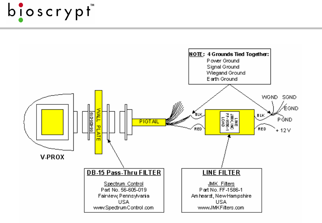
Appendix C – Installing the R&TTE Installation Kit Filters
The following two sections describe the proper procedures for installing the R&TTE
Installation Kit filters, which are required in certain European countries for full CE
compliance. These kits are required only for the V-Prox and V-Smart products and
are not required for any other Bioscrypt product. More information can be found
regarding the CE R&TTE directive online at the European Union web site:
http://www.europa.eu.int/comm/enterprise/rtte/index.htm
R&TTE Wiring Instructions for the V-Prox, A, H
In order to comply with the conducted emissions requirements of the European
Union (EU) directive EN 55022 for DC power input/output ports, an additional line
filter is needed for installations where power supply cables are greater than 3
meters in length. The required filter is manufactured by JMK Filters (Amhearst, New
Hampshire, USA), Part No. FF-1586-1, and is shipped as part of the installation kit.
Please note the orientation of the filter: the end labeled “LOAD” is to be
connected to the V-Prox device, the end labeled “LINE” is to be connected to
the system power supply.
In order to comply with the radiated emissions requirements of the European
Union R&TTE directive CISPR22, a high-density DB-15 “pass-thru” filter is required.
The required filter is manufactured by Spectrum Control (Fairview, Pennsylvania,
USA), Part No. 56-605-019, and is shipped as part of the installation kit. Please note
that it is necessary to rotate the filter to pass through the aperture of the wall plate
or mullion. It is easiest if the filter is first connected to the pigtail wiring harness
supplied. The cable assembly (and connected filter) is now rotated 90 degrees to
allow passage through the aperture of the wall plate. The V-Prox device should
next be connected to the cable assembly, and then pushed back through the
aperture until the wall plate is between the two mounting flanges of the filter. The
device may now be rotated back 90 degrees to the upright position and lowered
onto the mounting hooks of the wall plate.
Please see figure 16 for wiring details.
Page 25
Document #430-90003-16 © Copyright 2005 Bioscrypt Inc. All Rights Reserved.
Figure 16: V-Prox R&TTE Installation Kit Wiring Diagram
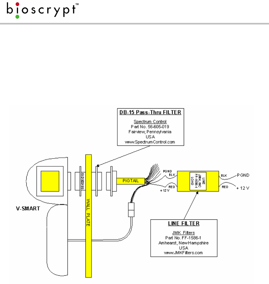
R&TTE Wiring Instructions for the V-Smart, A and V-Smart, A, H
In order to comply with the conducted emissions requirements of the European
Community directive EN 55022 for DC power input/output ports, an additional line
filter is needed for installations where power supply cables are greater than 3
meters in length. The required filter is manufactured by JMK Filters (Amhearst, New
Hampshire, USA), Part No. FF-1586-1, and is shipped as part of the installation kit.
Please note the orientation of the filter: the end labeled “LOAD” is to be
connected to the V-Smart device, the end labeled “LINE” is to be connected to
the system power supply.
In order to comply with the radiated emissions requirements of the European
Community R&TTE directive CISPR22, a high-density DB-15 “pass-thru” filter is
required. The required filter is manufactured by Spectrum Control (Fairview,
Pennsylvania, USA), Part No. 56-605-019, and is shipped as part of the installation
kit. Please note that it is necessary to rotate the filter to pass through the aperture
of the wall plate or mullion. It is easiest if the filter is first connected to the pigtail
wiring harness supplied. The cable assembly (and connected filter) is now rotated
90 degrees to allow passage through the aperture of the wall plate. The V-Smart
device should next be connected to the cable assembly, and then pushed back
Page 26
Document #430-90003-16 © Copyright 2005 Bioscrypt Inc. All Rights Reserved.
through the aperture until the wall plate is between the two mounting flanges of
the filter. The device may now be rotated back 90 degrees to the upright position
and lowered onto the mounting hooks of the wall plate.
Please see figure 17 for wiring details.
Figure 17: V-Smart R&TTE Installation Kit Wiring Diagram

Page 27
Document #430-90003-16 © Copyright 2005 Bioscrypt Inc. All Rights Reserved.
References
(1) B & B Electronics offers an Application Note on RS-485 devices, system
configuration, and termination.
B & B Electronics
707 Dayton Road
P.O. Box 1040
Ottawa, IL 61350
(815)433-5100
http://www.bb-elec.com
(2) Robust Data Comm provides services and a vast amount of information at
their WWW site.
Robust Data Comm, Inc.
St. Paul, MN 55112
(612)628-0533
http://www.robustdc.com
(3) The Specification is formally named TIA/EIA-485-A and can be purchased
from Global Engineering Documents:
http://global.ihs.com
(4) National Semiconductor provides a number of Application Notes:
http://www.national.com/an/AN/
(5) Belden Wire and Cable Company offers a variety of cables suitable for RS-
485 use and has a number of technical papers:
http://www.belden.com

Page 28
Document #430-90003-16 © Copyright 2005 Bioscrypt Inc. All Rights Reserved.
(6) Alpha Wire Company offers a variety of cables suitable for RS-485 use and
has a number of technical papers:
http://www.alphawire.com
(7) Cisco Systems, Inc., provides a comprehensive guide to Ethernet 802.x
standards and implementation issues:
http://www.cisco.com/univercd/cc/td/doc/cisintwk/ito_doc/ethernet.htm
(8) Charles Spurgeon provides an excellent online Ethernet resource:
http://www.ethermanage.com/ethernet/ethernet.html
(9) The CE R&TTE directive is outlined on the EU website at:
http://www.europa.eu.int/comm/enterprise/rtte/index.htm

Page 29
Document #430-90003-16 © Copyright 2005 Bioscrypt Inc. All Rights Reserved.
Bioscrypt Contact Information
Technical Support Contact Information:
Telephone: 866.304.7180 (toll free)
818.304.7180 (direct)
Fax: 818.304.7187
Email: support@bioscrypt.com
Web: http://www.bioscrypt.com
Hours: 5:30A – 5:00P PST (Monday – Friday)
Address: Bioscrypt Inc
Technical Support Dept
5805 Sepulveda Blvd, Suite 750
Van Nuys, CA, 91411
Corporate & Canadian Office
505 Cochrane Dr.
Markham, ON, Canada L3R 8E3
T 905 940 7750
F 905 940 7642
www.bioscrypt.com
U.S. Office
5805 Sepulveda Blvd., Suite 750
Van Nuys, CA 91411
T 818 304 7150
F 818 461-0843
U.K. Office
35 Jackson Court, Hazlemere
High Wycombe, Buckinghamshire
England HP15 7TZ
T +44 (0) 1494 814 404
F +44 (0) 1494 815 513
Veri-Series Setup Guide
© Copyright 2005 Bioscrypt Inc. All rights reserved. Document #430-00111-18 1
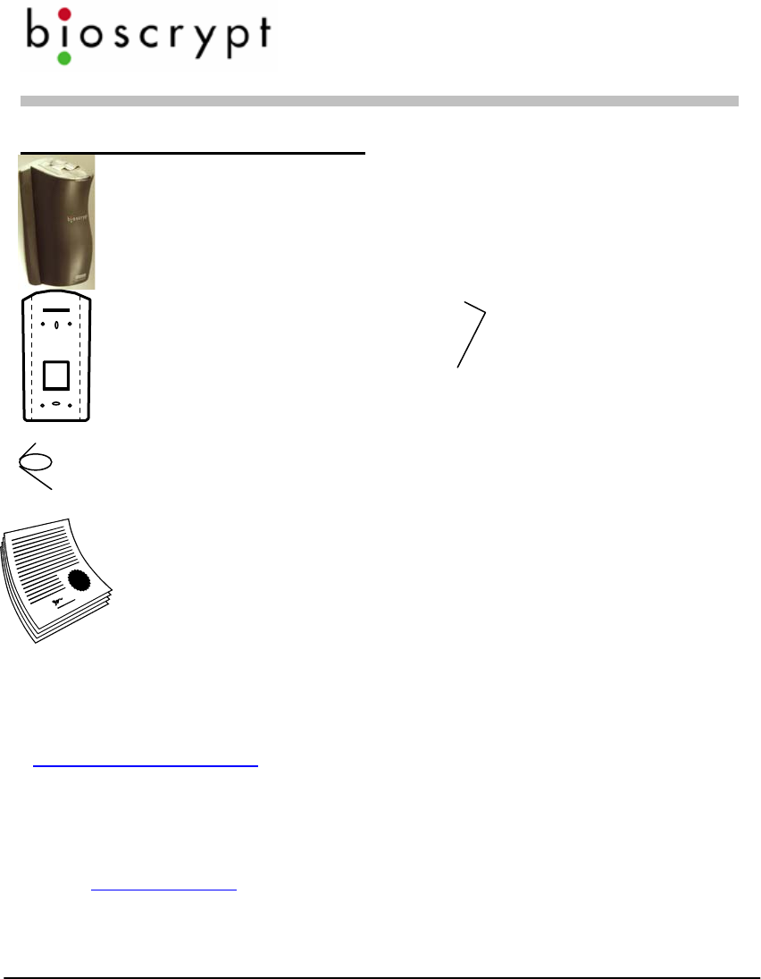
Checklist For Unpacking
Veri-Series reader
(V-Smart and V-Station differ
from picture shown)
Wall mounting plate /
Mullion mounting plate
(V-Smart and V-Station differ
from picture shown )
Tools
1/8” security hex key
Pigtail cable
(not included for V-Station)
Documentation
Veri-Series Setup Guide
Hardware
(4) #6-32 screws
(4) #6 self-tapping
screws
(4) #4-8 wall anchors
(14) crimps
(1) plastic Aux port
door
(2) #4-40 screws
Documentation provided with your new fingerprint reader is installed onto your
computer when you install the VeriAdmin software (also available online at
http://www.bioscrypt.com). To view the documentation you can use Windows
Explorer (available from the Start Menu under Programs) to navigate to
C:\Program Files\Bioscrypt\VeriAdmin\Docs or another location that you defined
during the installation procedure. The documentation is provided in Adobe®
Acrobat® format (PDF). The Adobe Acrobat reader is available on the CD or on-
line at www.adobe.com.
Veri-Series Setup Guide
© Copyright 2005 Bioscrypt Inc. All rights reserved. Document #430-00111-18 2
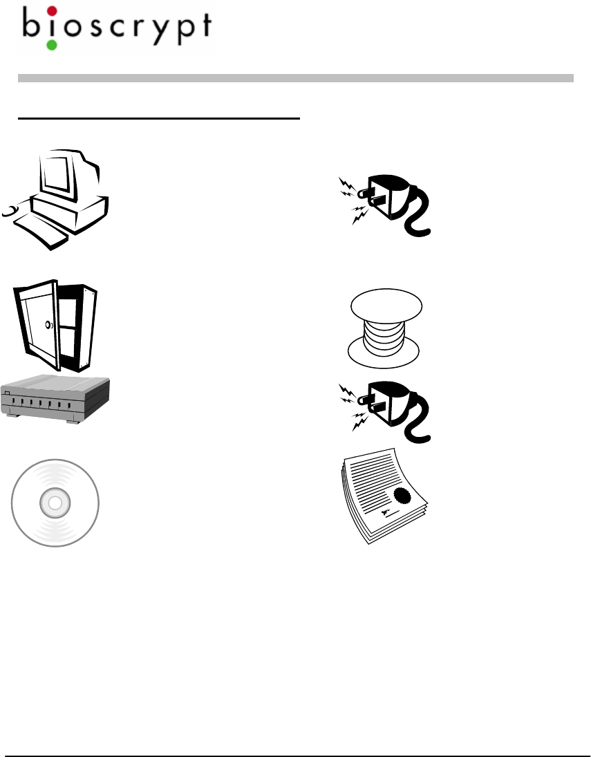
Other required equipment
PC (optional for V-Station)
One available COM port
(or Ethernet card)
Windows 98, ME, NT4,
2000, or XP
486-compatible
16 MB RAM
30 MB disk space
Power supply
Door controller
Networking cable
RS-232/RS-485 Converter
P/S for converter
CD with VeriAdmin
software and documentation
User Documentation
(included on
VeriAdmin CD)

Veri-Series Setup Guide
© Copyright 2005 Bioscrypt Inc. All rights reserved. Document #430-00111-18 3
Introduction
The Veri-Series Setup Guide provides you with general information on
installing your fingerprint reader and using the reader and associated software.
This document is not a substitute for the more comprehensive documentation
provided with your reader and available on the CD-ROM or installed on your
computer with the VeriAdmin software. Please refer to the Veri-Series
Installation Guide and the Veri-Series Operations Manual for additional
information. If there are any questions about information in this guide or in the
more comprehensive documentation please contact Bioscrypt Technical
Support using the contact information located in the Warranty and Returns
section of this document.
Please see the Release Announcement document on the CD-ROM for the latest
updates to this and other documentation.
Veri-Series Setup Guide
© Copyright 2005 Bioscrypt Inc. All rights reserved. Document #430-00111-18 4
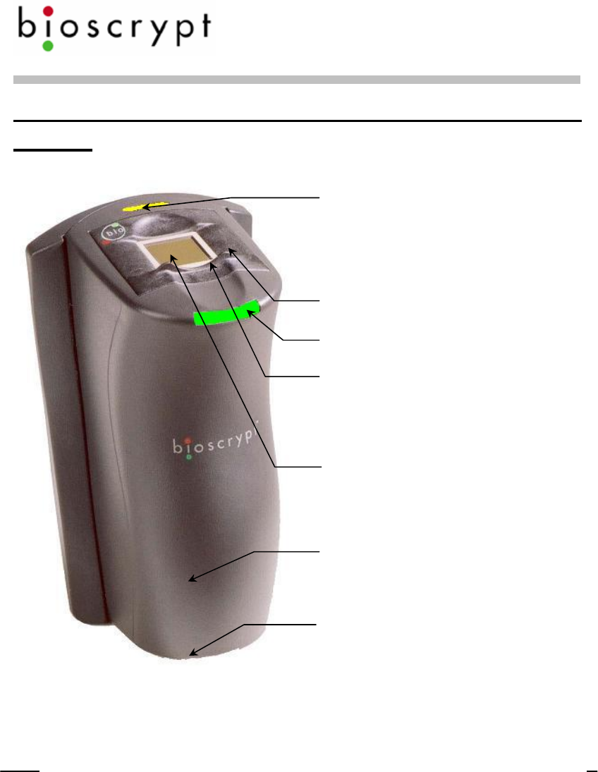
Learning More About Your New Fingerprint
Reader
Pass/Fail Indicator
Amber – place finger
Off – remove finger
Green – Pass
Red – Fail
Power Indicator
Conductive Plastic Mask
RidgeLock™ to aid in
consistent finger placement
Fingerprint Sensor
ABS Plastic Body
Aux. Port
Internally, your fingerprint reader is powered by hardware and software developed
b
y Bioscrypt. The “bioscrypt on board™” logo signifies that Bioscrypt's biometric
technology has been integrated into this product. It provides the assurance that
Bioscrypt's high standards of biometric quality and security reside within the
product.
Veri-Series Setup Guide
© Copyright 2005 Bioscrypt Inc. All rights reserved. Document #430-00111-18 5
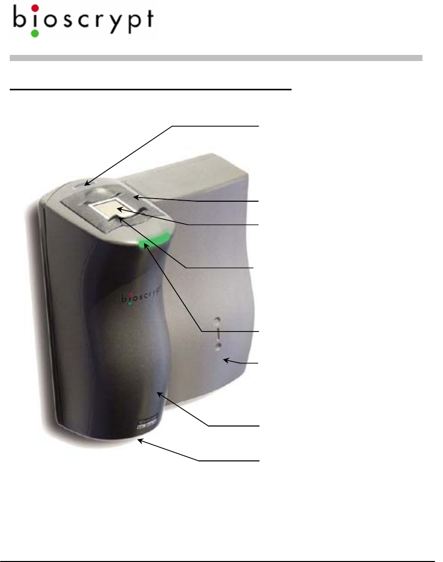
The V-Smart™ Fingerprint Reader
Pass/Fail Indicator
Amber – place finger
Off – remove finger
Green – Pass
Red – Fail
Conductive Plastic Mask
Fingerprint Sensor
RidgeLock™ to aid in consistent
finger placement
Power Indicator
MIFARE® or
iCLASS™ smart card
reader
ABS Plastic Body
Aux. Port
Veri-Series Setup Guide
© Copyright 2005 Bioscrypt Inc. All rights reserved. Document #430-00111-18 6
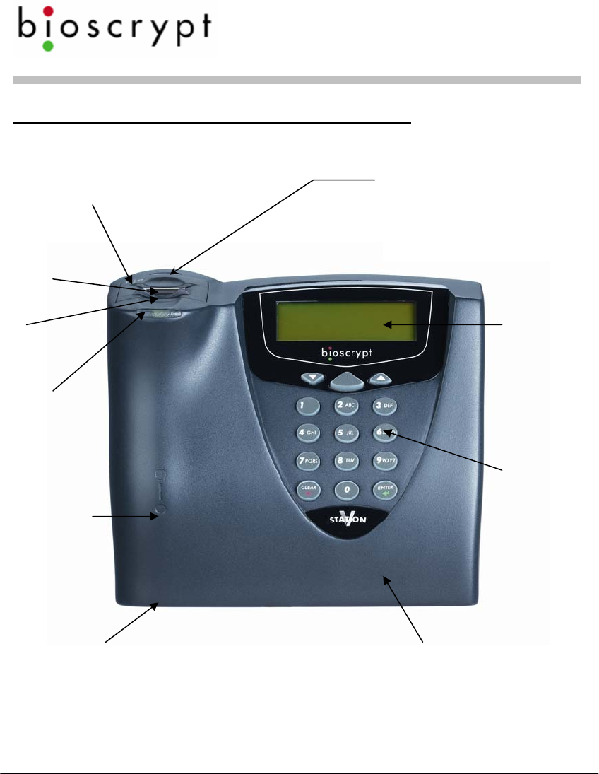
The V-Station™ Fingerprint Reader
Pass/Fail Indicator
Amber – place finger
Off – remove finger
Green – Pass
Red – Fail
Conductive Plastic
Fingerprint
Sensor
RidgeLock™
Power
Indicator
LCD Backlit
Display
Illuminated
Keypad
Some models:
MIFARE® or
iCLASS™ smart
card reader or
HID Proximity
reader
Aux. Port ABS Plastic Body

Veri-Series Setup Guide
© Copyright 2005 Bioscrypt Inc. All rights reserved. Document #430-00111-18 7
The Veri-Series Product Line
The Veri-Series fingerprint readers are used in access control and other related
fields. There are a variety of features common to the various products, but
there are differences as well, as described below. For more on the operational
differences between the products please see Basic Operation on page 29.
Common Features
The various products in the Veri-Series line have some features in common
such as both RS-232 and RS-485 serial communications protocol support
for connection to a PC, Wiegand input and output protocol support for
connection to access control equipment, a wide power input range (9-24
Volts DC) except for the V-Smart (9-12 Volts DC) and V-Station (12.5-24
Volts DC), and a requirement for earth ground connection to dissipate static
electricity (ESD).
Product Specific Differences
V-Prox™: The V-Prox has a built-in HID proximity card reader that negates
the need for external Wiegand input, and provides one-to-one fingerprint
authentication. The V-Prox is capable of storing up to 4000 fingerprint
templates (a “template” is a mathematical model of the fingerprint that is
generated during enrollment). The device can be mounted on door Mullion
or single-gang electrical box.
V-Flex™: The V-Flex has all the capabilities and features of the V-Prox
described above except that there is no built-in HID proximity card reader.
Therefore the V-Flex requires an external Wiegand input signal. The V-
Flex is designed for retrofit applications and for applications where a card
technology other than HID is desired.
V-Pass™: The V-Pass provides one-to-many fingerprint identification for
small user populations (the system is optimized for user populations up to
100, but can be used for populations up to 200). The V-Pass provides
fingerprint only identification – no cards or PINs are required to use the

Veri-Series Setup Guide
© Copyright 2005 Bioscrypt Inc. All rights reserved. Document #430-00111-18 8
system. The V-Pass is also small enough to be mounted on a door mullion
or a single-gang electrical box.
V-Smart™: The V-Smart supports one-to-one fingerprint authentication by
means of an industry standard MIFARE®-compatible or iCLASS™
contactless smart card reader. The fingerprint template is stored on the
smart card, not on the reader, so the user population is unlimited – simply
issue a smart card to each employee.
V-Station™: The newest addition to the Veri-Series product line, the V-
Station contains a backlit LCD display and keypad, enabling template
management and unit configuration directly from the unit; a PC is not
required. Variations of this product are offered with an HID proximity card
reader, a Smartcard reader (MIFARE or iCLASS), or as a searching unit.
Also, this is the first product to offer Ethernet support. It is probably the
most versatile product in the Veri-Series.
MIFARE® is a registered trademark of Philips Semiconductors
iCLASS™ is a trademark of HID Corporation
Veri-Series Setup Guide
© Copyright 2005 Bioscrypt Inc. All rights reserved. Document #430-00111-18 9
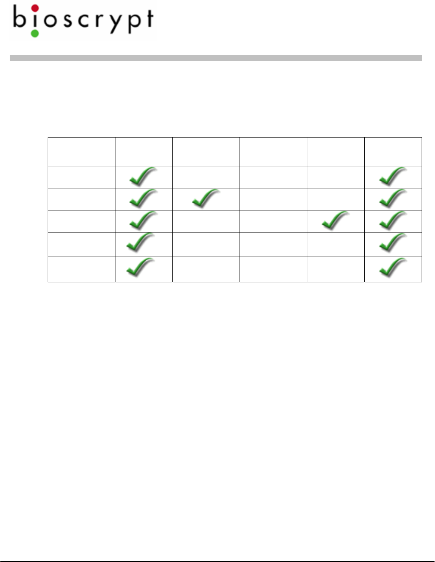
Required Connections
The following table shows required and optional connections to the various
products.
Product Power
Input Wiegand
Input Wiegand
Output Serial
Comm. Earth
Ground
V-Prox *** **
V-Flex *** **
V-Pass ***
V-Smart * ***
V-Station * *** **
* The power input on V-Smart is 9-12 VDC and 12.5-24VDC on V-Station instead of 9-24
VDC on the other products.
** RS-485 communication is typically used for template distribution to multiple units.
*** Wiegand output is typically used to send the user information (ID number and facility
code from card) to an access control panel, but this connection is not strictly required.
Veri-Series Setup Guide
© Copyright 2005 Bioscrypt Inc. All rights reserved. Document #430-00111-18 10
Preparing Wiring
1. Wiring connections to be made:
Wiegand – should be 18-22 AWG (10-7 MWG) wire, between 3 and 6
conductors depending on which signals will be carried, shielded cable is
recommended, and typically the conductors are made of stranded wire.
Minimum connections: Data0, Data1, Wiegand Ground
RS-485 – use category 5 shielded cable.
Ethernet – use category 5 shielded cable
Power – should be 18 – 22 AWG (10 – 7 MWG) wire, 2 conductors.
Earth Ground – use a single wire with heaviest gauge reasonable.
Warning: Do not use Power Ground as a substitute for Earth Ground.
Veri-Series Setup Guide
© Copyright 2005 Bioscrypt Inc. All rights reserved. Document #430-00111-18 11
2. Pigtail Connections (V-Prox, V-Flex, V-Pass, V-Smart):
Pin # Signal Description Original Cable New Cable
Jacket Gray Blue
1 Wiegand Out Data 0 Red w/ Black Green
2 Wiegand In Data 0 Green w/ Black Green/White
3 Wiegand Out Data 1 Org White
4 Wiegand In Data 1 Org w/ Black White/Black
5 Line Trigger Green Gray
6 Wiegand GND Red Black/White
7 RS-485 (-) Blue w/ Black Blue/Black
8 RS-485 (+) White Blue
9 RS-232 Tx Black w/ White Violet
10 RS-232 Rx Red w/ White Violet/White
11 Power GND Black Black
12 Signal GND Green w/ White Black/Red
13 Power input (9-24 VDC)
*(9-12 VDC) for V-Smart Blue w/ White Red
14 Reserved Blue Red/White
15 Earth ground White w/ Black Green/Yellow
Veri-Series Setup Guide
© Copyright 2005 Bioscrypt Inc. All rights reserved. Document #430-00111-18 12
3. Weidmuller Connections (V-Station only):
Group Label Signal Description
RS-485 TX(+) Transmit +
TX(-) Transmit -
RX(+) Receive +
RX(-) Receive -
GND RS-485 Ground
RS-232 GND RS-232 Ground
TX Transmit
RX Receive
Power/Ground +(POS) 12.5 - 24 VDC +
-(NEG) 12.5 - 24 VDC -
EGND Earth Ground
Wiegand IN 0 Data 0 In
IN 1 Data 1 In
OUT 0 Data 0 Out
OUT 1 Data 1 In
LED IN LED In
LED OUT LED Out
GND Wiegand Ground
TTL (IN) IN 0 TTL Data 0 In
IN 1 TTL Data 1 In
TTL (OUT) OUT 0 H TTL Data 0 Out
OUT 1 L TTL Data 1 Out
GND TTL Ground
4. [RS-485 network only]: Use a daisy chain network design as depicted in the
following figure. Do not use a star or other multi-drop configuration.
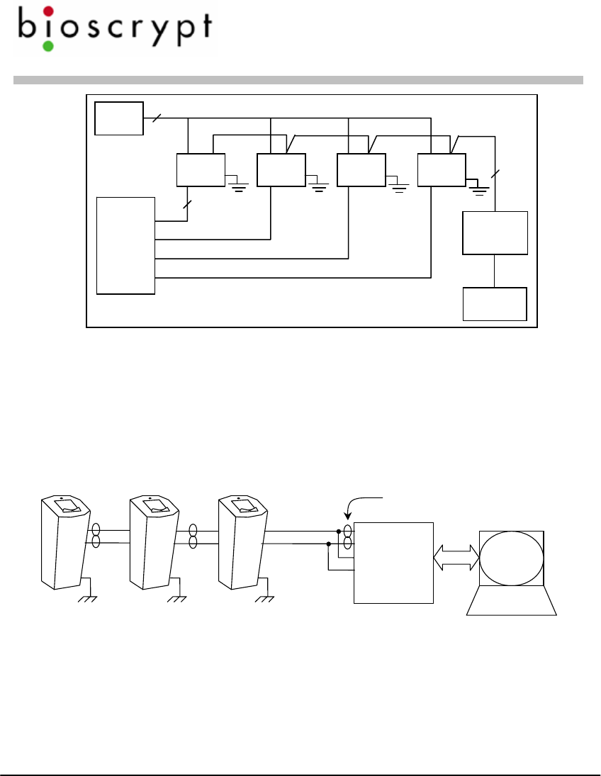
Veri-Series Setup Guide
© Copyright 2005 Bioscrypt Inc. All rights reserved. Document #430-00111-18 13
Use one pair (e.g. blue/white and white/blue) for RS-485 connections.
Connect readers identically at each reader (e.g. blue/white on Cat5 to RS-
485 (-) on pigtail/Weidmuller Connector and white/blue on Cat5 to RS-485
(+) on pigtail/Weidmuller Connector).
Power
Supply
Unit Unit Unit Unit
3Data0
Data1
Wiegand Gnd.
2
RS-232
/RS-485
Converter
Cat5
Twisted
Pair
Computer
Door
Controller
5. [RS-485 network only]: At converter, jumper TD(A) with RD(A) and
TD(B) with RD(B). Connect Blue/white from Cat5 to either of A terminals
and White/blue from Cat5 to either of B terminals. Make certain to connect
power correctly.
RS-232
TD(A)
TD(B)
RD(A)
RD(B)
+12VDC
GND
Twisted Pair.
Use Cat5 rated cable
RS-485 (+)
RS-485 (-)
Connect to
Earth Ground
6. [RS-485 network only]: RS-485 supports distances up to 4,000 feet (1,200
meters) and/or 31 readers. To extend these limitations, contact Bioscrypt
Technical Support. Typically no end-of-line termination is required unless
the total run exceeds 2,000 feet.
7. [RS-485 network only]: Set up network using 9600 baud rate. Only
increase this data rate after the system is operating properly at 9600.

Veri-Series Setup Guide
© Copyright 2005 Bioscrypt Inc. All rights reserved. Document #430-00111-18 14
8. [Ethernet network only]: Typically a star network topology is used with a
network switch or hub, but a bus topology may be used. Be sure to connect
all devices using straight-thru (as apposed to cross-over) cables. The
exception to this is when connecting a single device directly to the
computer Ethernet adaptor.
9. [Ethernet network only]: Up to 254 readers can reside on a single Ethernet
bus, although repeaters may be required to boost the signal over longer
distances. The V-Station supports 10base-T Ethernet (10 Mbps)*. A 10
Mbps Ethernet network supports distances up to 100 meters (328 ft.)
between readers (2,500m with repeaters). Bioscrypt recommends isolating
your network of readers from computers (other than the admin PC) and
other devices to maximize security. A firewall is highly recommended if
the network will include other devices or PCs. For obvious reasons, it is not
a good idea to expose your network of readers to the outside world (i.e., the
Internet).
*Ethernet communication is supported in firmware versions 7.10 and higher.
VeriAdmin 5.10 or higher is required for administration over Ethernet.
Veri-Series Setup Guide
© Copyright 2005 Bioscrypt Inc. All rights reserved. Document #430-00111-18 15
Configuring Readers
See Page 11 for Color Codes
1. Set up a configuration station
a. Wire the unit for power:
• V-Prox/V-Flex/V-Pass: Connect the RED pigtail wire to 9-24V
DC power and the BLACK wire to power ground.
• V-Smart: Connect the RED pigtail wire to 9-12V DC power and
the BLACK wire to power ground.
• V-Station: Connect 12.5-24V power in to the +(POS)
Weidmuller connector and the power ground to the –(NEG)
connector.
b. Optionally wire up Wiegand output to a door controller.
c. Have a computer running VeriAdmin software available.
d. Have RJ11 communications cable available.
2. Connect the reader for communication
a. Connect RJ11 to reader and DB9 to PC COM port.
b. Plug pigtail cable into reader (if not a V-Station) and connect power
to appropriate conductors identified in the charts on pages 11 and
12.
Wiegand Ground
Wiegand Out Data1
Wiegand Out Data0
Power
Supply
+12 VDC
Pigtail OR Ground
Door
Controller
Data 0
Data 1
Common
Earth
Ground
Weidmuller
To
Com
p
ute
r
Veri-Series Setup Guide
© Copyright 2005 Bioscrypt Inc. All rights reserved. Document #430-00111-18 16
3. Configure the device using the VeriAdmin software provided
a. If running VeriAdmin for the first time, you will be directed to the
Network Setup dialog. This dialog is also reached by clicking on
this icon: . Select the serial (COM) port(s) you intend to use or
Ethernet and click OK. It is recommended that you check “Auto”.
Veri-Series Setup Guide
© Copyright 2005 Bioscrypt Inc. All rights reserved. Document #430-00111-18 17
b. This will bring you to the Network Configuration Manager dialog.
First click on the Comm port or Ethernet within the network tree
which you have connected the unit to (the or icon). Then
click on the “Add Unit” button (lower left).
Veri-Series Setup Guide
© Copyright 2005 Bioscrypt Inc. All rights reserved. Document #430-00111-18 18
c. VeriAdmin should establish communication with the unit. The Unit
Status field should indicate ONLINE, you may hear the unit beep,
and other fields on the right side should populate. If you are
connecting via Ethernet, you must first assign the unit an IP address
from the unit’s keypad and then type in the address under Ethernet
Settings and click the Refresh button.
d. If VeriAdmin shows NOT RESPONDING, check the connections
and then press the Refresh button to try again.
e. You may assign the unit a name (default is “New Bioscrypt Unit”) if
desired.
f. The network tree shown on the left will show a small icon
representing the current unit , just below the icon under the
port you selected. Double-click on this icon to open the Unit
Parameters dialog.
Veri-Series Setup Guide
© Copyright 2005 Bioscrypt Inc. All rights reserved. Document #430-00111-18 19
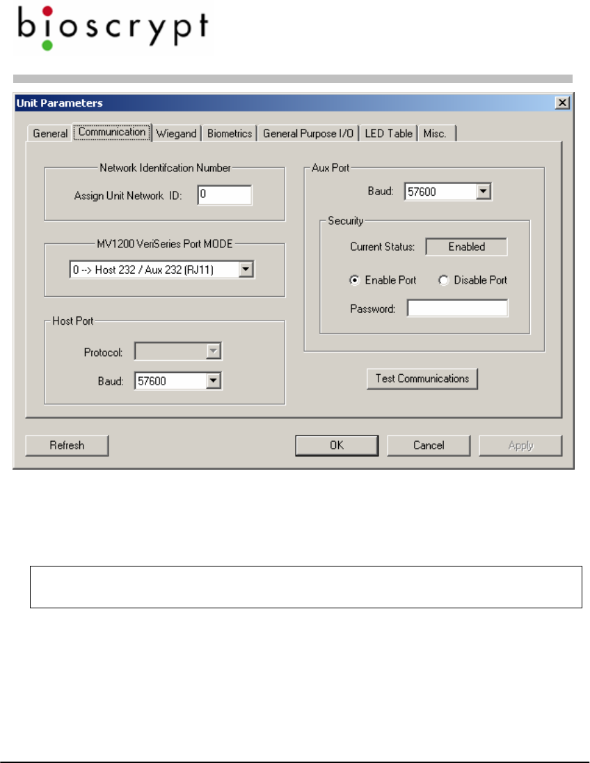
g. Change desired parameters. Typical changes are:
i. Communication Tab: Network ID (default is 0, but each
unit must have a unique ID number such as 1, 2, 3, 4, etc.)
ii. Wiegand Tab: Wiegand parameters
NOTE: We do not recommend changing the Aux. port Baud rate at this
time.
4. Repeat steps 2-4 (skipping 3a) for the next reader until all readers are
configured.

Veri-Series Setup Guide
© Copyright 2005 Bioscrypt Inc. All rights reserved. Document #430-00111-18 20
5. If placing units on a RS-485 network, you will also need to set up the
computer for RS-485 communications.
a. Connect the RS-232/RS-485 converter to the PC’s COM port (must
support Send Data – a means of automatically sensing data sent
from the RS-232 port – we suggest the B&B Electronics, www.bb-
elec.com, model 485TBLED or equivalent).
b. Run category 5 rated cable from the converter to the first reader in
the daisy chain.
6. V-Smart considerations
a. The V-Smart does not require an RS-485 network. There is no need
to distribute templates because the templates are carried by the users
in the cards.
b. One security aspect of the V-Smart is that a site key is used to
secure the information on the smart card. If a card is presented to
the V-Smart it uses the programmed site key to unlock the data from
the card. The V-Smart is shipped with a default site key (a blank
field). If the programmed site key does not unlock the data from the
card, the user cannot verify their fingerprint. This provides system
administrators with a means to further protect their facilities from
unauthorized access.
c. If the system administrator wants to periodically change the site key
(to further minimize the risk of compromised or lost cards), then this
can be done through an RS-485 network or by making the
appropriate changes to the reader through the Aux port.

Veri-Series Setup Guide
© Copyright 2005 Bioscrypt Inc. All rights reserved. Document #430-00111-18 21
7. V-Station considerations
a. The V-Station does not require configuration via a PC. Nearly all
configuration options can be set using the menus on the unit.
However, it may be more convenient to administer the device from
the PC due to the limited size of the LCD screen.
b. To distribute templates to other V-Stations, you will need to place
all V-Stations on a network and administer them via the PC.
Alternatively, templates can be stored on the PC and transferred to
each V-Station separately, via the Host, Aux, or Ethernet ports.
c. To access some advanced features such as the transaction log, you
will need to communicate with the V-Station from the PC.
d. Connecting to a V-Station via Ethernet should be done by a network
administrator or one familiar with TCP/IP operations. The V-
Station should be assigned an appropriate IP address or be set to use
DHCP*. Caution should be exercised when manually assigning IP
addresses: it should be appropriate for the given network and should
not conflict with other devices or PCs on the network. Bioscrypt
recommends isolating all V-Stations on a closed Ethernet network,
both for security reasons and to avoid conflicts with other
computers and devices on the network.
* DHCP may not be available in some firmware versions.
Veri-Series Setup Guide
© Copyright 2005 Bioscrypt Inc. All rights reserved. Document #430-00111-18 22
Mounting Readers On The Wall
1. The readers come disassembled, however, if your reader has previously been
assembled then disassemble the reader body and smart card module (for V-
Smart only) from the wall plate.
a. On V-Smart remove security screw securing smart card module
b. For products other than V-Station, remove security screw securing
the Aux. port cover, and remove the Aux. port cover by twisting (see
graphics on page 25).
c. Remove #4-40 screw securing reader body to wall plate.
d. Remove smart card module (on V-Smart only) and reader body by
sliding up and pulling away from the wall plate.
e. Keep screws and Aux. port cover for re-assembling the device.
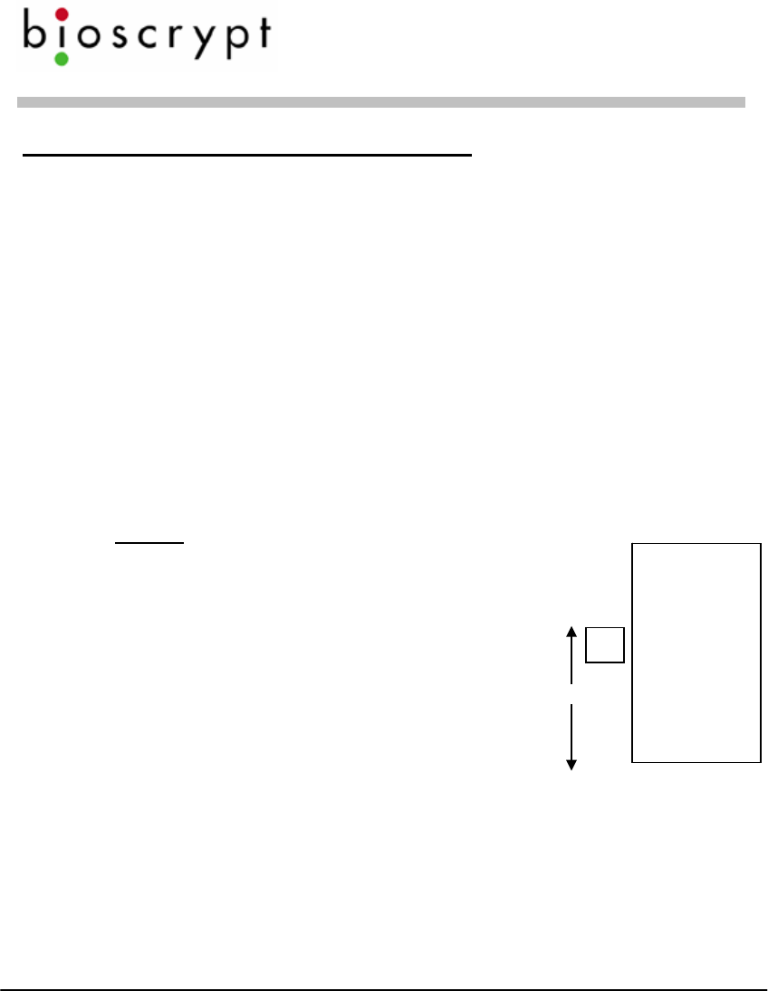
2. Define a location. A good location will have these qualities:
a. Comfortable height for finger placement
NOTE: If readers need to be mounted above
54” or below 48”, please contact Bioscrypt for
available accessories to properly readjust the
angle of the reader for optimal finger
placement. Mounting a reader above or below
the recommended height will not be
ergonomic for the user and will not promote
good finger placement on the sensor. 48” – 54”
b. ADA considerations
c. Provide clearance above and below for
access
d. The access hole in the wall for wiring should be less than 1 ½ inches
wide so that wall plate will cover it. It should be less than 1 ½
inches tall if mounting into dry wall so that there is enough material
to hold the anchor. The recommended size is 1 inch wide by 1 1/8
inches tall to match the opening in the wall plate.
e. For V-Smart, the access hole in the wall for wiring should be less
than 4 ½ inches wide so that wall plate will cover it. It should be

Veri-Series Setup Guide
© Copyright 2005 Bioscrypt Inc. All rights reserved. Document #430-00111-18 23
less than 2 ½ inches tall if mounting into dry wall so that there is
enough material to hold the anchor. The recommended size is 3 ½
inches wide by 2 ½ inches tall.
f. For V-Station, the rear of the unit will protrude past the wall plate
and into the wall approximately 1 inch (depending on the
Weidmuller connectors attached). The access hole must be exactly
the size of the hole in the wall plate (136mm (~5 3/8”) wide by
69mm (~2 ¾”) tall). It may be helpful to trace the edges of the hole
in the wall plate in pencil before cutting.
g. Please see pages 26 – 28 for templates for the single-gang and
double-gang mounting plates. These templates are dimensioned in
millimeters (mm).
3. Make pigtail (or Weidmuller for V-Station) wiring connections to power,
Wiegand or other connections prior to mounting wall plate.
4. For the V-Smart, feed pigtail cable from Smart Card Module through hole
in wall plate from the front and connect to pigtail cable already wired in
wall cutout.
5. For the V-Smart, connect Smart Card Module to wall plate. Line up four
tabs, push forward and then down. Secure smart card module with the
security screw at the bottom.
6. Feed main pigtail DB15 connector (not applicable to V-Station) through
wall plate from the back and proceed to mount wall plate:
a. Optionally mount to a gang box using #6-32 screws provided.
b. Optionally mount on wall.
i. Use 4 outer mounting points (6 for V-Station).
ii. Up to #6 screws can be accepted (screws and drywall anchors
are provided).
c. Use template provided to mark holes.
Veri-Series Setup Guide
© Copyright 2005 Bioscrypt Inc. All rights reserved. Document #430-00111-18 24
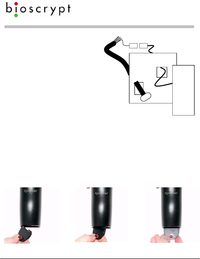
7. Attach pigtail to the reader body
(not applicable to V-Station) and
attach body to wall plate using
same motion as for the smart card
module. Secure the body to the
wall plate with the #4-40 screw at
the bottom. Replace the Aux.
port cover (see next page).
8. The RJ11 security cover is
removed to install the reader
body to the wall mount. Once the screw is in place, the security cover can
be snapped into place using the following procedure:
With the textured side facing down,
1) place left tab into left corner groove on reader body
2) rotate cover until right tab easily slides into groove
3) with tab in the reader body groove, rotate the cover clockwise until the
right tab snaps into place at the right rear corner
Step 1 Step 2 Step 3

Veri-Series Setup Guide
© Copyright 2005 Bioscrypt Inc. All rights reserved. Document #430-00111-18 25
4) Finally, fold the cover up and secure it using the supplied security screw
and special Allen wrench.
The following pages show the dimensions of the wall mounting plates for the
smaller Veri-Series readers (V-Prox, V-Flex, V-Pass), the V-Smart, and the V-
Station. The diagrams are not to scale however full-scale drawings can be
found in the Veri-Series Installation Guide.
Veri-Series Setup Guide
© Copyright 2005 Bioscrypt Inc. All rights reserved. Document #430-00111-18 26
5/32”
ø
1 1/8”
(
28
5 5/16”
(
135 mm
)
3 ¼”
(82 mm)
1”
(25
1 1/8”
(28 mm)
11/16”
(
17 mm
)
1 ¼”
(32 mm)
2 ¾”
(7 )0 mm
2 5/8”
(6 )7 mm
Mounting Template for V-Prox / V-Flex / V-Pass (not to scale)
Veri-Series Setup Guide
© Copyright 2005 Bioscrypt Inc. All rights reserved. Document #430-00111-18 27
Mounting Template for V-Smart (MIFARE and iCLASS) (not to scale)
Veri-Series Setup Guide
© Copyright 2005 Bioscrypt Inc. All rights reserved. Document #430-00111-18 28
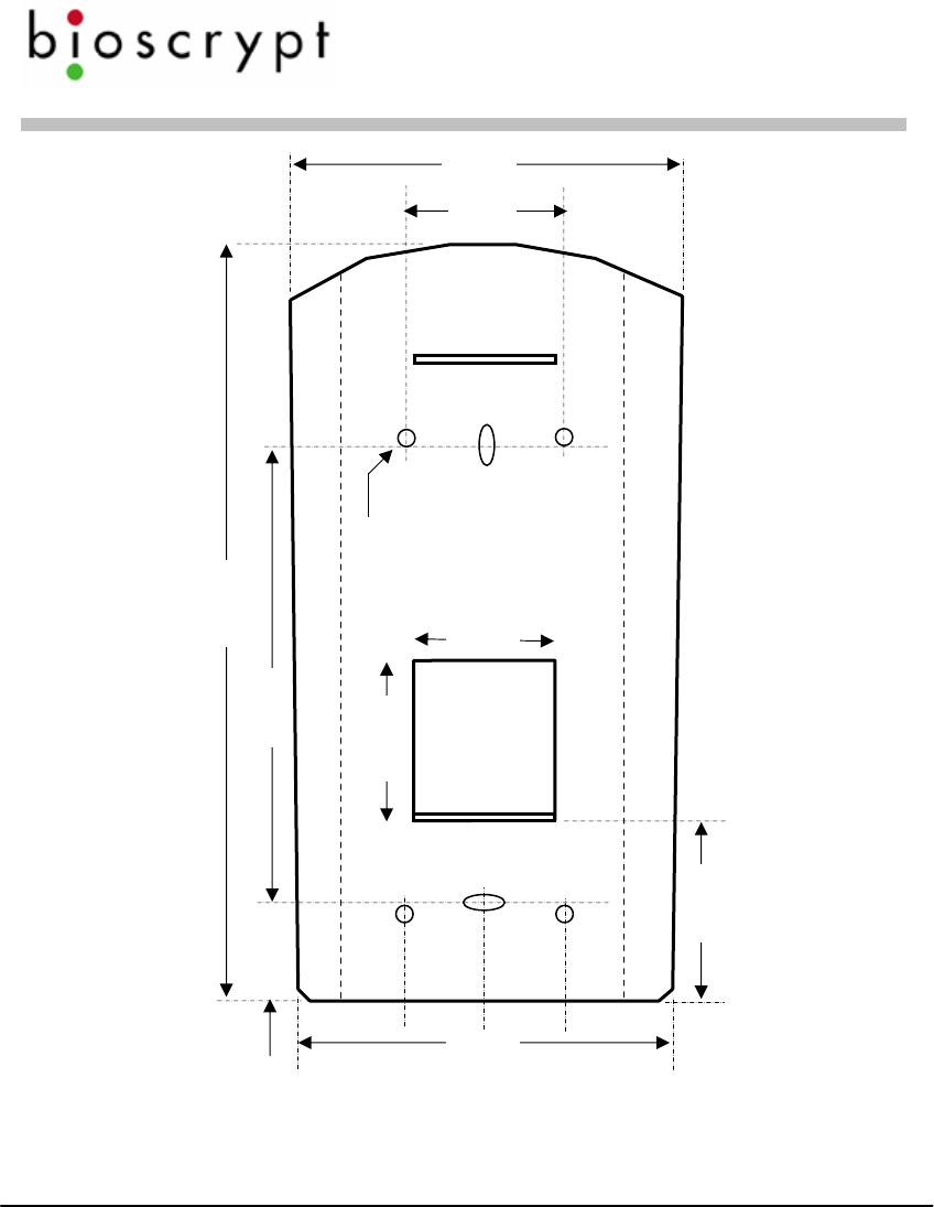
Mounting template for V-Station (all models) (not to scale)
Veri-Series Setup Guide
© Copyright 2005 Bioscrypt Inc. All rights reserved. Document #430-00111-18 29
Basic Operation
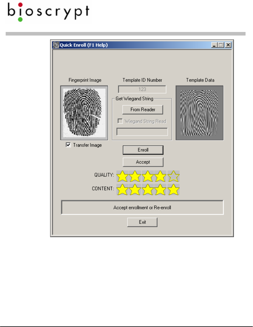
1. Use VeriAdmin software to enroll a new fingerprint:
Enrollment is the process of generating data
that the reader will store and use to later verify
your identity.
a. Make sure that the correct unit is identified on the main toolbar
dropdown.
b. Go to the Template Manager screen.
c. Click on Quick Enroll.
d. Enter an ID number. This can be the number of the user card (prox,
bar code, magnetic stripe, or other technology) or some other
number such as when using the V-Pass or V-Smart.
e. Click on the Enroll button – User must place their finger on the
sensor when the light turns amber and leave their finger on sensor
until the light goes out. Use the RidgeLock during enrollment to
obtain a finger placement consistent with what would be expected
during Verification. The ridge should comfortably fit in the first
crease of the finger. Do not use thumbs for enrollment or
verification.
f. The enrollment will be scored in
terms of Content and Quality on
a scale of 0-5 stars. Bioscrypt
recommends a minimum score of
3 stars for quality and 2 stars for
content. If enrollment scores for
Content and Quality are
acceptable, then click on Accept.
Quality is a measure of how
clearly the fingerprint is shown
in the image.
Content measures how unique
(i.e., curvy) the captured pattern
is.
Veri-Series Setup Guide
© Copyright 2005 Bioscrypt Inc. All rights reserved. Document #430-00111-18 30
g. Fill in desired information and decide where the template will be
stored (either on PC, the unit used to enroll, or a smart card). Click
on the appropriate “Save” button.
h. If templates are saved to the PC or the unit and are to be distributed
to other readers, then this can be done using the Template Manager
functions. In the case of V-Smart, the template is stored on the
smart card and does not need to be distributed.
Veri-Series Setup Guide
© Copyright 2005 Bioscrypt Inc. All rights reserved. Document #430-00111-18 31
2. Using the keypad to enroll a new fingerprint (V-Station only):
a. From the idle screen (showing ”Bioscrypt” with the date and time),
press 0-0-0 (three zeroes) and . You will be warned about no
admin ID.
b. You are now in the V-Station menu system. From here you may
traverse the menus using the and buttons, the button
to enter a menu, and the button to back out to the previous
menu.
c. Enter the Template Admin menu, then the Enroll (Add) User menu.
Enter an enroll ID between 1 and 4294967294.
d. Place your finger on the sensor when the amber LED turns on,
making sure to use the RidgeLock.
e. After retrieving the live fingerprint, you will be shown the content
and quality in stars (asterisks) (5 is the best). Bioscrypt
recommends at least 3 stars for quality and 2 for content. To accept
the enrollment, press 1. To reject it, press 2. To re-try enrollment,
press 3.
f. Choose the finger enrolled, 0 - 9 (0 = left pinky, 9 = right pinky).
You may press if you don’t want to specify a finger.
g. Choose whether the finger should be a Duress finger or not (0 = No,
1 = Yes, or simply for No).
h. Choose the security level, 0 – 6 (0 = none, 1 = very high, 2 = high,
… 5 = very low, 6 = Password Only). You may press for the
default (3).
i. Choose the admin level 0 – 2 (0 = user, 1 = enroller, 2 = full admin).
You may press for the default (user).
j. Enter a password for the template, if desired, or for none.
k. If the unit is a V-Station MIFARE or V-Station iCLASS, the next
menu will ask if you would like to save the template to the unit (1)
Veri-Series Setup Guide
© Copyright 2005 Bioscrypt Inc. All rights reserved. Document #430-00111-18 32
or to a smart card (2). If saving to a smart card, you will need to
enter the current site key (it must be numeric, and is set using
VeriAdmin) and then present an appropriate fresh or blank smart
card.
l. Finally, you may elect to enroll an alternate finger with the same ID.
Press 1 for yes or 2 for no
3. Verification is as simple as:
Verification is the process of comparing a live
fingerprint scan to the fingerprint data stored
during enrollment.
a. Present the card to reader (unless using a V-Pass in which case, skip
to b) or enter your ID number at the keypad if using a V-Station
(when in idle mode).
b. When the light turns yellow place the finger on sensor in same
position as when it was enrolled and hold. Use the RidgeLock to
position your fingerprint on the sensor. This will help to generate
consistent finger placement. The ridge should fit comfortably in the
first crease of your finger.
c. When the light turns off, remove the finger and the door lock will
release if the verification was successful (reader will indicate green
for success or red for failure).
4. Cleaning and care of the sensor
The fingerprint sensor is a solid-state device designed to provide years
of trouble-free service. Although there is little to do in terms of
maintenance, a few basics in caring for the sensor will help to ensure a
high level of performance over the life of the sensor.
Oily deposits from your finger accumulate on the surface of the
fingerprint sensor after repeated use. These deposits can degrade the

Veri-Series Setup Guide
© Copyright 2005 Bioscrypt Inc. All rights reserved. Document #430-00111-18 33
performance of the system. Cleaning can be done regularly but is only
required when a significant amount of residue builds up on the sensor.
To clean the sensor, use a clean, soft cloth dipped in isopropyl (rubbing)
alcohol. Use a sweeping motion to remove deposits from the sensor.
Do not use a soiled cloth or any abrasive brushes, pads or detergents.

Veri-Series Setup Guide
© Copyright 2005 Bioscrypt Inc. All rights reserved. Document #430-00111-18 34
Disclaimer
The instructions in this document have been carefully checked for accuracy and
are presumed to be reliable. Bioscrypt, Inc. and its writers assume no
responsibility for inaccuracies and reserve the right to modify and revise this
document without notice.
It is always our goal at Bioscrypt, Inc. to supply accurate and reliable
documentation. If you discover a discrepancy in this document, please e-mail
your comments to support@bioscrypt.com, or contact Bioscrypt Technical
Support at the telephone number listed below.
No part of this publication may be placed in a retrieval system, transmitted, or
reproduced in any way, including, but not limited to, photograph, photocopy,
computer disk or other record, without prior agreement and written permission
from:
Bioscrypt Inc.
5805 Sepulveda Blvd.
Suite 750
Van Nuys, CA 91411
Phone 818.304.7150
Toll Free 888.982.4643
http://www.bioscrypt.com

Veri-Series Setup Guide
© Copyright 2005 Bioscrypt Inc. All rights reserved. Document #430-00111-18 35
Bioscrypt One Year Limited Warranty Policy
Bioscrypt warrants to the original consumer purchaser (“Customer”) that new
Bioscrypt products will be free from defects in material and workmanship for
one year from the date the product was shipped from Bioscrypt. For
replacement products the warranty on the replacement unit is the remainder of
the warranty on the original product or ninety (90) days, whichever is longer.
The Customer is responsible for making any claims for shipment damage
(evident or concealed) with the freight carrier. Bioscrypt must be notified
within thirty days of shipment of incorrect materials.
If a defect is discovered, Bioscrypt's sole obligation shall be to repair or replace
the Bioscrypt product(s) at its sole discretion at no charge, provided it is
returned to Bioscrypt during the warranty period and is shipped freight and
insurance prepaid. Merchandise must be properly packaged to prevent damage
during shipping. Before returning a Bioscrypt product, contact Bioscrypt
Technical Service to obtain a Return Material Authorization (RMA) number.
No product may be returned whether in warranty or out of warranty without
first obtaining approval from Bioscrypt. The model number, invoice number,
and serial number may be required for warranty service.
This warranty shall not apply to any product or any part of a product, which in
the judgment of Bioscrypt, has been subjected to misuse, negligence, alteration,
accident, improper maintenance, or damage by excessive physical or electrical
stresses. Tampering, such as opening the housing of a biometric reader or
replacing parts will void this warranty. The warranty is void if the serial
number of the Bioscrypt product has been defaced, altered, or removed or if the
product has been modified. Repair and replacement parts will be furnished on
an exchange basis and may be either reconditioned or new. All replaced parts
or products become the property of Bioscrypt. This warranty may also be
voided for failure to comply with Bioscrypt’s return policy.
The warranty is not applicable to:
• Abnormal wear and tear

Veri-Series Setup Guide
© Copyright 2005 Bioscrypt Inc. All rights reserved. Document #430-00111-18 36
• Damage caused during installation
• Damage caused by the equipment or system with which the biometric reader is
used
• Damage caused by modification or repairs not made or authorized by Bioscrypt
• Damage caused by improper packaging
• Damage caused by lack of ESD protection
• Merchandise that is determined to be stolen
All Veri-Series units have an operating temperature range of 0°-60° Celsius
(32°-140° Fahrenheit). In addition, the Veri-Series product line has a relative
humidity operating range of 0-95% non-condensing. Any device used outside
that temperature or humidity range requires an enclosure with thermal or
humidity control that can maintain a consistent environment within the stated
operating ranges.
The newest Bioscrypt Veri-Series products are designed to be weather resistant
but no sensor technology exists today that can work in all weather
environments. If a Bioscrypt Veri-Series product is not used in a completely
indoor environment, then a protective enclosure is required to shield the unit
from moisture, dust, other contaminants and temperatures outside the stated
operating range. Product failures resulting from exposure to these conditions
are not covered under the product warranty.
For outdoor installations, Bioscrypt does offer an enclosure to protect the
device from exposure to moisture, dust, other contaminants and temperatures
outside stated operating range. To maintain the Bioscrypt warranty, the Veri-
Series unit must be installed in a Bioscrypt certified outdoor enclosure. When
used properly, this enclosure will protect Veri-Series devices in most
environments, but not all. The Customer is responsible for determining
whether the offered enclosure will appropriately shield Veri-Series devices in
their specific installation. Product failures resulting from exposure to moisture,
dust, other contaminants and temperatures outside stated operating range, even
if an enclosure is used, are not covered under the product warranty.

Veri-Series Setup Guide
© Copyright 2005 Bioscrypt Inc. All rights reserved. Document #430-00111-18 37
This warranty is exclusive and in lieu of all others, whether oral or written,
expressed or implied. Bioscrypt specifically disclaims any and all implied
warranties, including without limitation, warranties of merchantability and
fitness for any particular purpose. No Bioscrypt dealer, agent, or employee is
authorized to make any modification, extension or addition to this warranty.

Veri-Series Setup Guide
© Copyright 2005 Bioscrypt Inc. All rights reserved. Document #430-00111-18 38
Bioscrypt Return Policy and Procedures
Bioscrypt must be notified within thirty days of the date that a defect is
discovered. Bioscrypt will then issue a Return Material Authorization (RMA)
number which the Customer must include with all correspondence and display
on the outside of the shipping container when returning the product. Any
products returned later than 30 days after issuance of an RMA may be subject
to review as to whether the authorization to return is still warranted.
All Bioscrypt products must be shipped freight and insurance prepaid, in the
original shipping container or equivalent. A written description of the defect
together with a copy of the invoice and the name of the Dealer who sold the
Bioscrypt product must be shipped with the product. All defects must be
reproducible at Bioscrypt’s location to qualify for this limited warranty.
For shipping addresses and return authorization contact Bioscrypt Technical
Support. Warranty repairs do not re-initiate the warranty period. For repaired
or replaced products the warranty on the replacement unit is the remainder of
the warranty on the original product or 90 days, whichever is longer.
Bioscrypt will return a repaired or replacement product via ground freight and
insurance prepaid. If the Customer desires an airfreight or other expedited
return shipping method, then they must agree to pay for the expedited shipping.
Returned products that are found to be free of defects may be subject to a
$150.00 handling fee and will be returned at the Customer’s expense.

Veri-Series Setup Guide
© Copyright 2005 Bioscrypt Inc. All rights reserved. Document #430-00111-18 39
Carefully read the following regarding billable repairs:
By shipping product to Bioscrypt using the RMA provided by the Technical
Support Department, you are agreeing to the following terms:
For all non-warranty repairs or billable repairs, the customer will be responsible
for charges associated with parts, labor and shipping/freight to and from the
Bioscrypt repair facility. Once the product is evaluated/inspected by a repair
technician, Bioscrypt will provide the customer with an estimate of the
aforementioned charges.
If any discrepancies arise between the final cost and the initial estimate, the
customer will be notified.
The customer shall approve any estimate for non-warranty repairs or billable
repairs and shall pay the estimated charges before the equipment is repaired. In
the event the customer fails to either: (a) pay the estimated charges within 60
days of such estimate; or (b) arrange for return of the un-repaired equipment to
the customer at customer’s cost, Bioscrypt will consider the equipment
abandoned and will dispose of the equipment.

Veri-Series Setup Guide
© Copyright 2005 Bioscrypt Inc. All rights reserved. Document #430-00111-18 40
30 Day Return for Credit
Bioscrypt is a leading biometric company, specializing in fingerprint and
verification systems. We are confident that customers will be pleased with
Bioscrypt products. However, if you are not, and you purchased your
merchandise directly from Bioscrypt, new products can be returned for credit
within the first 30 days under the following conditions:
• You have received an RMA from Bioscrypt Technical Support and the item
is returned in accordance with the Bioscrypt Return Policy and Procedures.
• Return Items are accompanied by proof of purchase.
• All original materials (accessories, manuals, CDs) are returned with the
item.
• The item is in re-sellable condition. If there are any questions regarding re-
sellable condition Bioscrypt will have the final decision as to whether an
item can be returned or exchanged.
If you did not purchase your product directly from Bioscrypt Inc, please contact
your retailer for their return policy.

Veri-Series Setup Guide
© Copyright 2005 Bioscrypt Inc. All rights reserved. Document #430-00111-18 41
Notices
The Veri-Series line of products has been tested for compliance with all
applicable international standards. The resulting approvals are listed below,
and are additionally printed on the labeling located on the rear panel of the
product.
The power supply offered by Bioscrypt is CE and CSA approved and UL listed.
V-Flex FCC, UL 294, CSA, CE
V-Prox FCC, UL 294, CSA, CE
V-Pass FCC, UL 294, CSA, CE
V-Smart FCC, UL 294, CSA, CE
V-Station FCC, UL 294, CSA, CE
For more information on approvals, notices, and declarations of conformance
for all Veri-Series products, please see Appendix A and B within the Veri-
Series Installation Guide. Important FCC, CE, and R&TTE information is
listed there.

Veri-Series Setup Guide
© Copyright 2005 Bioscrypt Inc. All rights reserved. Document #430-00111-18 42
Technical Support Contact Information:
Telephone: 866.304.7180 (toll free)
818.304.7180
Fax: 818.304.7187
Email: support@bioscrypt.com
Web: http://www.bioscrypt.com
Hours: 5:30A – 5:00P PST (Monday – Friday)
Address Bioscrypt Inc.
Technical Support Department
5805 Sepulveda Blvd., Suite 750
Van Nuys, CA 91411

Veri-Series Setup Guide
© Copyright 2005 Bioscrypt Inc. All rights reserved. Document #430-00111-18 43
For your records
Model:
Serial Numbers:
Installer/Reseller:
Installation Date:
Notes:
Corporate & Canadian Office
505 Cochrane Dr.
Markham, ON, Canada L3R 8E3
T 905 940 7750
F 905 940 7642
www.bioscrypt.com
U.S. Office
5805 Sepulveda Blvd., Suite 750
Van Nuys, CA 91411
T 818 304 7150
F 818 461-0843
U.K. Office
35 Jackson Court, Hazlemere
High Wycombe, Buckinghamshire
England HP15 7TZ
T +44 (0) 1494 814 404
F +44 (0) 1494 815 513