Biostar A780L3L Owners Manual A78LC M3S_111003
2014-07-31
: Biostar Biostar-A780L3L-Owners-Manual biostar-a780l3l-owners-manual biostar pdf
Open the PDF directly: View PDF ![]() .
.
Page Count: 49

A780L3L Setup Manual
FCC Information and Copyright
This equipment has been tested and found to comply with the limits of a Class
B digital device, pursuant to Part 15 of the FCC Rules. These limits are designed
to provide reasonable protection against harmful interference in a residential
installation. This equipment generates, uses, and can radiate radio frequency
energy and, if not installed and used in accordance with the instructions, may
cause harmful interference to radio communications. There is no guarantee
that interference will not occur in a particular installation.
The vendor makes no representations or warranties with respect to the
contents here and specially disclaims any implied warranties of merchantability
or fitness for any purpose. Further the vendor reserves the right to revise this
publication and to make changes to the contents here without obligation to
notify any party beforehand.
Duplication of this publication, in part or in whole, is not allowed without first
obtaining the vendor’s approval in writing.
The content of this user’s manual is subject to be changed without notice and
we will not be responsible for any mistakes found in this user’s manual. All the
brand and product names are trademarks of their respective companies.

Table of Contents
Chapter 1: Introduction ........................................ 1
1.1 Before You Start ................................................................................ 1
1.2 Package Checklist............................................................................. 1
1.3 Motherboard Features...................................................................... 2
1.4 Rear Panel Connectors ..................................................................... 3
1.5 Motherboard Layout......................................................................... 4
Chapter 2: Hardware Installation .......................... 5
2.1 Installing Central Processing Unit (CPU)....................................... 5
2.2 FAN Headers...................................................................................... 7
2.3 Installing System Memory................................................................ 8
2.4 Connectors and Slots ....................................................................... 10
Chapter 3: Headers & Jumpers Setup ................... 13
3.1 How to Setup Jumpers .................................................................... 13
3.2 Detail Settings.................................................................................. 13
Chapter 4: RAID Functions .................................. 18
4.1 Operating System............................................................................ 18
4.2 Raid Arrays ...................................................................................... 18
4.3 How RAID Works............................................................................. 18
Chapter 5: Useful Help ........................................ 21
5.1 Driver Installation Note.................................................................. 21
5.2 Software ............................................................................................ 22
5.3 Extra Information............................................................................ 26
5.4 Troubleshooting............................................................................... 28
Appendix: SPEC In Other Languages ................... 30
German.................................................................................................................. 30
French .................................................................................................................... 32
Italian..................................................................................................................... 34
Spanish ................................................................................................................... 36
Portuguese ............................................................................................................ 38
Polish...................................................................................................................... 40
Russian ................................................................................................................... 42
Arabic..................................................................................................................... 44
Japanese ................................................................................................................ 46

A780L3L
1
CHAPTER 1: INTRODUCTION
1.1 BEFORE YOU START
Thank you for choosing our product. Before you start installing the
motherboard, please make sure you follow the instructions below:
Prepare a dry and stable working environment with
sufficient lighting.
Always disconnect the computer from power outlet
before operation.
Before you take the motherboard out from anti-static
bag, ground yourself properly by touching any safely
grounded appliance, or use grounded wrist strap to
remove the static charge.
Avoid touching the components on motherboard or the
rear side of the board unless necessary. Hold the board
on the edge, do not try to bend or flex the board.
Do not leave any unfastened small parts inside the
case after installation. Loose parts will cause short
circuits which may damage the equipment.
Keep the computer from dangerous area, such as heat
source, humid air and water.
1.2 PACKAGE CHECKLIST
HDD Cable X 1 (optional)
Serial ATA Cable X 2
Rear I/O Panel for ATX Case X 1
Installation Guide X 1
Fully Setup Driver CD X 1 (full version manual files inside)
FDD Cable X 1 (optional)
USB 2.0 Cable X1 (optional)
S/PDIF out Cable X 1 (optional)
Serial ATA Power Cable X 1 (optional)
Note: The package contents may be different due to area or your motherboard version.

Motherboard Manual
2
1.3 MOTHERBOARD FEATURES
SPEC
CPU
Socket AM3
AMD Sempron / Athlon II / Phenom II
processors
(Maximum Watt: 95W)
AMD 64 Architecture enables 32 and 64 bit
computing
Supports Hyper Transport 3.0
FSB Support HyperTransport 3.0
Supports up to 3.2 GT/s Bandwidth
Chipset AMD RS780L
AMD SB710
Super I/O
ITE 8721
Provides the most commonly used leg acy
Super I/O functionality
Low Pin Count Interface
Environment Control in it iatives
H/W Monitor
ITE's "Smart Guardian" function
Main
Memory
DDR3 DIMM Slots x 2
Max Memory Capacity 8GB
Each DIMM supports 512MB/
1GB/2GB/4GB DDR3
Dual Channel Mode DDR3 memory modu le
Supports DDR3 800 / 1066 / 1333
Registered DIMM and ECC DIMM is not supported
Graphics Integrated in AMD RS780L Chipset Max Shared V ideo Memory is 512 MB
DVI/HDCP support
IDE Integr ated IDE Contro lle r Ultra DMA 33 / 66 / 100 / 133 Bus Master Mode
supports PIO Mode 0~4,
SATA II Integrated Serial ATA Controller Data transfer rates up to 3 Gb/s
SATA Version 2.0 specificat ion co mp liant
LAN Realtek RTL 8103EL 10 / 100 Mb/s auto negotiation
Half / Full duplex capability
Sound ALC662 5.1 channels audio out
High Definition Audio
PCI Express Gen2 x16 slot x1 Supports PCI-E Gen2 x16 expansion cards
Slots PCI slot x2 Supports PCI expansion cards
Floppy Connector x1 Each connector supports 2 Floppy drives
IDE Connector x1 Each connector supports 2 IDE devices
SATA Connector x4 Each connector supports 1 SATA device
Front Panel Connector x1 Supports front panel facilities
On Board
Connectors
Front Audio Connector x1 Supports front panel audio function
A780L3L
3
SPEC
S/PDIF out Connector x1 Supports digital audio out function
CPU Fan Header x1 CPU Fan power supply (with Smart Fan function)
System Fan Header x1 System Fan Power supply
CMOS clear Header x1 Restore CMOS data to factory default
USB Connector x2 Each connector supports 2 front panel USB ports
Power Connector (24pin) x1 Connects to Power supply
Power Connector (4pin) x1 Connects to Power supply
Printer Port Connector x1 Each connector supports 1 Printer port
Serial Port Connector x1 Connects to RS-232 Port
Back Panel
I/O
PS/2 Keyboard x1
PS/2 Mouse x1
DVI port x1
VGA port x1
LAN port x1
USB Port x4
Audio Jack x3
Connects to PS/2 Keyboard
Connects to PS/2 Mouse
Connect to DVI-D monitor
Connect to D-SUB monitor
Connect to RJ-45 Ethernet cable
Connect to USB devices
Provide Audio-In/Out and microphone connection
Board Size 182 mm(W) x 235 mm(L)
Special
Features RAID 0 / 1 / 1+0 support
OS Support Windows XP / Vista / 7 Biostar reserves the right to add or remove support
for any OS With or without notice.
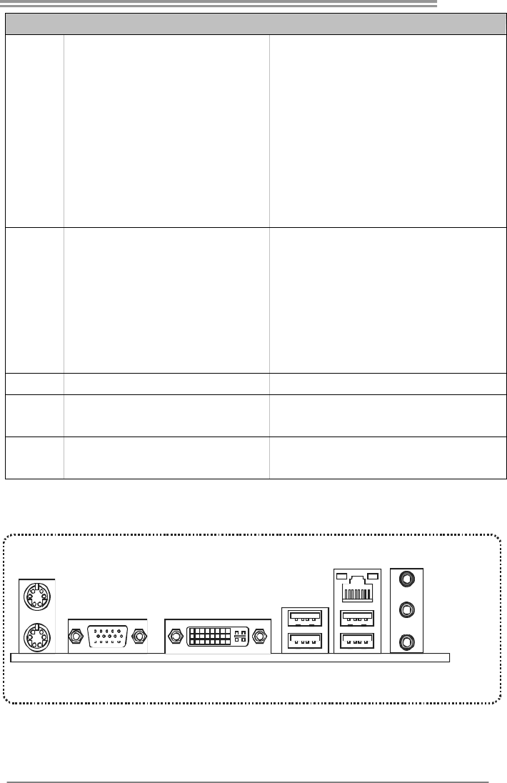
1.4 REAR PANEL CONNECTORS
PS/2
Mou se
PS/2
Keyboard
USBX2USBX2
LAN
VGA
Line In/
Surround
Line Out
Mic In 1/
Bass/ Center
DVI-D
Motherboard Manual
4
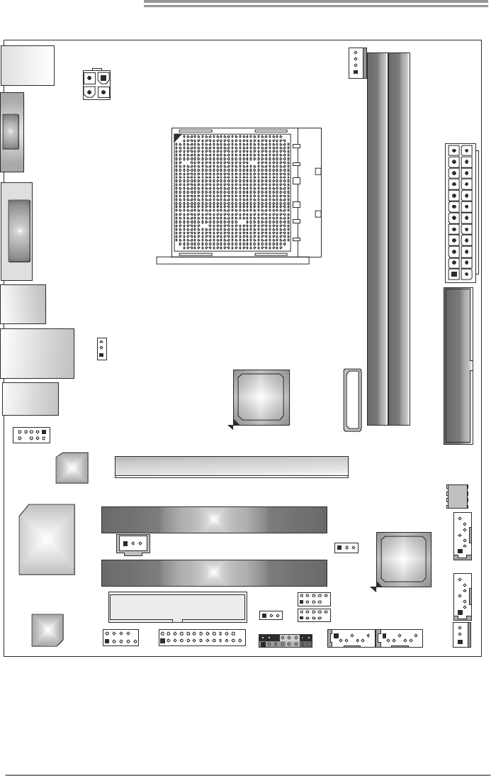
1.5 MOTHERBOARD LAYOUT
KBMS1
USB1
RJ45USB1
VGA1 DVI1
AUDIO1
JUSBV1
F_AUDIO1
LAN
Super
I/O
Codec
PEX16_1
PCI1
PCI2
FDD1
JUSBV2
J_PRINT1J_COM1 PANEL1
F_USB2
F_USB1
SATA1 SATA2
SYS_FAN1
SATA3
SATA4
BIOS
IDE1
ATXPWR 1
D3_A1DR
DB1DR3_
CPU_FAN1
BATTERY
ATXPWR 2
AMD
RS780L
AMD
SB710
JCMOS1
JSPDIFOUT1
Socket AM3
Note: represents the 1■st pin.
A780L3L
5
CHAPTER 2: HARDWARE INSTALLATION
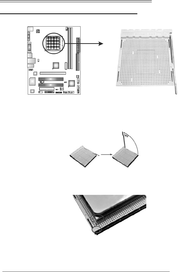
2.1 INSTALLING CENTRAL PROCESSING UNIT (CPU)
Step 1: Pull the lever toward direction A from the socket and then raise the
lever up to a 90-degree angle.
Step 2: Look for the white triangle on socket, and the gold triangle on
CPU should point towards this white triangle. The CPU will fit only
in the correct orientation.
Motherboard Manual
6
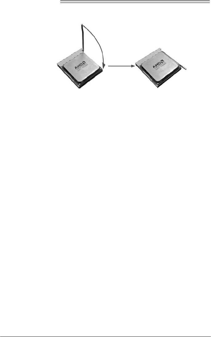
Step 3: Hold the CPU down firmly, and then close the lever toward direct
B to complete the installation.
Step 4: Put the CPU Fan on the CPU and buckle it. Connect the CPU
FAN power cable to the CPU_FAN1. This completes the
installation.
A780L3L
7
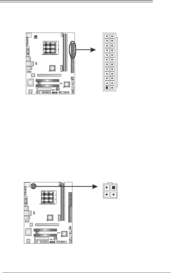
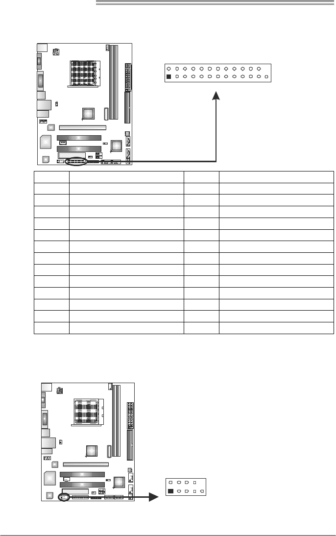
2.2 FAN HEADERS
These fan headers support cooling-fans built in the computer. The fan
cable and connector may be different due to the fan manufacturer.
Connect the fan cable to the connector while matching the black wire to
pin#1.
CPU_FAN1: CPU Fan Header
Pin
Assignment
1 Ground
2 +12V
3 FAN RPM rate
sense
1
4
4 Smart Fan
Control (By Fan)
SYS_FAN1: System Fan Header
Pin
Assignment
1 Ground
2 +12V
1
3
3 FAN RPM rate
sense
Note:
The CPU_FAN1 supports 4-pin head connector. The SYS_FAN1 supports 3-pin head
connector. When connecting with wires onto connectors, please note that the red wire is
the positive and should be connected to pin#2, and the black wire is Ground and should
be connected to GND.
Motherboard Manual
8
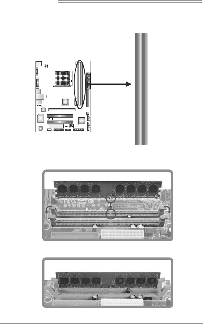
2.3 INSTALLING SYSTEM MEMORY
A. Memory Modules
DB1DR3_
D3_A1DR
1. Unlock a DIMM slot by pressing the retaining clips outward. Align a
DIMM on the slot such that the notch on the DIMM matches the
break on the Slot.
2. Insert the DIMM vertically and firmly into the slot until the retaining
chip snap back in place and the DIMM is properly seated.

A780L3L
9
B. Memory Capacity
DIMM Socket
Location DDR3 Module Total Mem ory
Size
DDR3_A1 512MB/1GB/2GB/4GB
DDR3_B1 512MB/1GB/2GB/4GB
Max is 8GB.
C. Dual Channel Memory installation
Please refer to the following requirements to activate Dual Channel function:
Install memory module of the same density in pairs, shown in the table
Dual Channel Status DDR3_A1 DDR3_B1
Disabled X O
Disabled O X
Enabled O O
(O means memory installed, X means memory not installed.)
The DRAM bus width of the memory module must be the same (x8 or
x16)
Motherboard Manual
10
2.4 CONNECTORS AND SLOTS
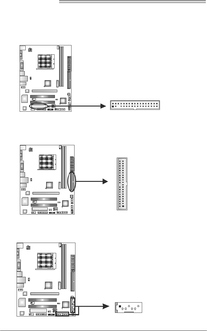
FDD1: Floppy Disk Connector
The motherboard provides a standard floppy disk connector that supports 360K,
720K, 1.2M, 1.44M and 2.88M floppy disk types.
133
234
IDE1: Hard Disk Connector
The motherboard has a 32-bit Enhanced PCI IDE Controller that provides PIO
Mode 0~4, Bus Master, and Ultra DMA 33/66/100/133 functionality.
21
3940
SATA1~SATA4: Serial ATA Connectors
The motherboard has a PCI to SATA Controller with 4channels SATA interface, it
satisfies the SATA 2.0 spec and with transfer rate of 3Gb/s.
Pin Assignment
1 Ground
2 TX+
3 TX-
4 Ground
5 RX-
6 RX+
74
1
SATA1 SATA2
SATA4
SATA3
7 Ground
A780L3L
11
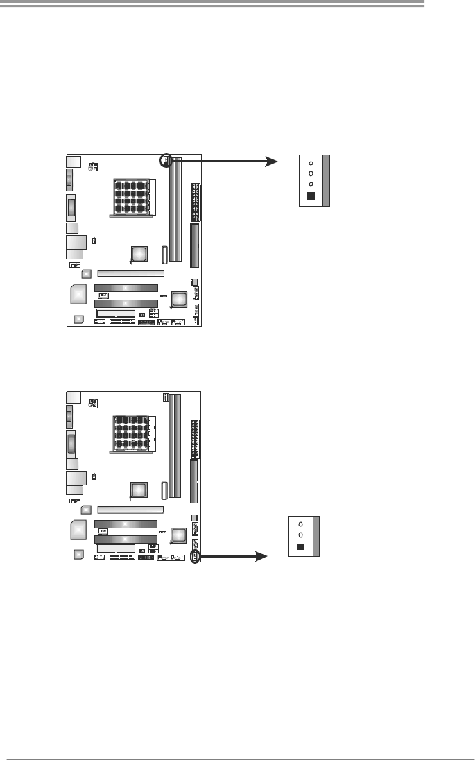
ATXPWR1: ATX Power Source Connector
This connector allows user to connect 24-pin power connector on the ATX
power supply.
1
12
13
24
Pin Assignment Pin Assignment
13 +3.3V 1 +3.3V
14 -12V 2 +3.3V
15 Ground 3 Ground
16 PS_ON 4 +5V
17 Ground 5 Ground
18 Ground 6 +5V
19 Ground 7 Ground
20 NC 8 PW_OK
21 +5V 9 Standby Voltage+5V
22 +5V 10 +12V
23 +5V 11 +12V
24 Ground 12 +3.3V
ATXPWR2: ATX Power Source Connector
Connecting this connector provides +12V to CPU power circuit.
Pin
Assignment
1 +12V
2 +12V
3 Ground
34
12
4 Ground
Note:
Before you power on the system, please make sure that both ATXPWR1 and ATXPWR2
connectors have been plugged-in.
Motherboard Manual
12
PEX16_1: PCI-Express Gen2 x16 Slot
- PCI-Express 2.0 compliant.
- Maximum theoretical realized bandwidth of 8GB/s simultaneously per
direction, for an aggregate of 16GB/s totally.
- PCI-Express supports a raw bit-rate of 5.0Gb/s on the data pins.
- 2X bandwidth over the PCI-Express 1.1 architecture.
PEX16_1
PCI1~PCI2: Peripheral Component Interconnect Slots
This motherboard is equipped with 2 standard PCI slots. PCI stands for
Peripheral Component Interconnect, and it is a bus standard for expansion
cards. This PCI slot is designated as 32 bits.
PCI1
PCI2
A780L3L
13
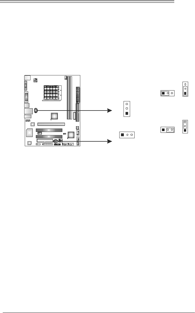
CHAPTER 3: HEADERS & JUMPERS SETUP
3.1 HOW TO SETUP JUMPERS
The illustration shows how to set up jumpers. When the jumper cap is
placed on pins, the jumper is “close”, if not, that means the jumper is
“open”.
Pin opened Pin closed Pin1-2 closed
3.2 DETAIL SETTINGS
PANEL1: Front Panel Header
This 16-pin connector includes Power-on, Reset, HDD LED, Power LED, and
speaker connection. It allows user to connect the PC case’s front panel switch
functions.
18
16
PW R_ LED
On/Off
RST
HLED
SPK
++
+
9
-
-
Pin Assignment Function Pin Assignment Function
1 +5V 9 N/A
2 N/A 10 N/A N/A
3 N/A 11 N/A N/A
4 Speaker
Speaker
Connector
12 Power LED (+)
5 HDD LED (+) 13 Power LED (+)
6 HDD LED (-)
Hard drive
LED 14 Power LED (-)
Power LED
7 Ground 15 Power button
8 Reset control Reset button 16 Ground Power-on button
Motherboard Manual
14
F_USB1/F_USB2: Headers for USB 2.0 Ports at Front Panel
These headers allow user to connect additional USB cable on the PC front panel,
and also can be connected with internal USB devices, like USB card reader.
Pin
Assignment
1 +5V (fused)
2 +5V (fused)
3 USB-
4 USB-
5 USB+
6 USB+
7 Ground
8 Ground
9 NC
19
210
FUSB_1
FUSB_2
10 Key
JCMOS1: Clear CMOS Header
Placing the jumper on pin2-3 allows user to restore the BIOS safe setting and
the CMOS data.lPease carefully follow the procedures to avoid damaging the
motherboard.
13
Pin 1-2 Close:
Normal Operation (default).
13
13
Pin 2-3 Close:
Clear CMOS data.
Clear CMOS Procedures:※
1. Remove AC power line.
2. Set the jumper to “Pin 2-3 close”.
3. Wait for five seconds.
4. Set the jumper to “Pin 1-2 close”.
5. Power on the AC.
6. Reset your desired password or clear the CMOS data.
A780L3L
15
F_AUDIO1: Front Panel Audio Header
This header allows user to connect the front audio output cable with the PC front
panel. This header allows only HD audio front panel connector; AC’97 connector
is not acceptable.
Pin
Assignment
1 Mic Left in
2 Ground
3 Mic Right in
4 GPIO
5 Right line in
6 Jack Sense
7 Front Sense
8 Key
9 Left line in
19
210
10 Jack Sense
JSPDIFOUT1: Digital Audio-out Connector
This connector allows user to connect the PCI bracket SPDIF output header.
Pin
Assignment
1 +5V
2 SPDIF_OUT
13
3 Ground
Motherboard Manual
16
J_PRINT1: Printer Port Connector
This header allows you to connector printer on the PC.
125
226
Pin Assignment Pin Assignment
1 -Strobe 14 Ground
2 -ALF 15 Data 6
3 Data 0 16 Ground
4 -Error 17 Data 7
5 Data 1 18 Ground
6 -Init 19 -ACK
7 Data 2 20 Ground
8 -Scltin 21 Busy
9 Data 3 22 Ground
10 Ground 23 PE
11 Data 4 24 Ground
12 Ground 25 SCLT
13 Data 5 26 Key
J_COM1: Serial port Connector
The motherboard has a Serial Port Connector for connecting RS-232 Port.
Pin
Assignment
1 Carrier detect
2 Received data
3 Transmitted data
4 Data terminal ready
5 Signal ground
6 Data set ready
7 Request to send
8 Clear to send
9 Ring indicator
1
210
9
10 NC
A780L3L
17
JUSBV1/JUSBV2: Power Source Headers for USB Ports
Pin 1-2 Close:
JUSBV1: +5V for USB ports at USB1/RJ45USB1.
JUSBV2: +5V for USB ports at front panel (F_USB1/F_USB2).
Pin 2-3 Close:
JUSBV1: +5V STB for USB ports at USB1/RJ45USB1.
JUSBV2: +5V STB for USB ports at front panel (F_USB1/F_USB2).
13
3
1
Pin 1-2 close
13
3
1
JUSBV2
JUSBV1
13
3
1
Pin 2-3 close
Motherboard Manual
18
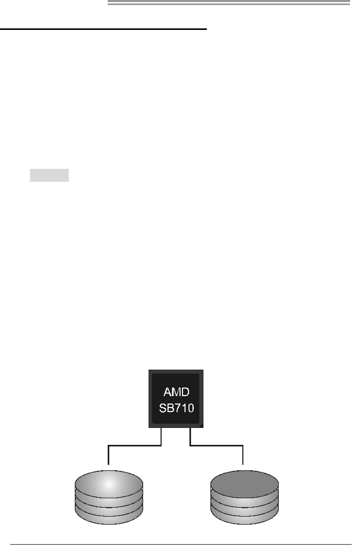
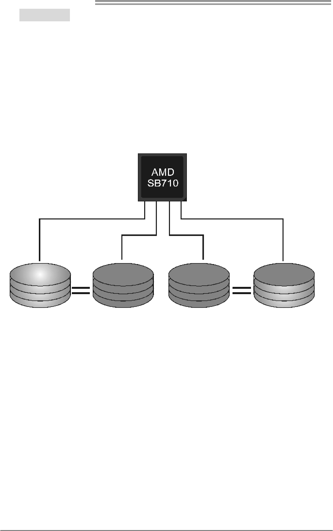
CHAPTER 4: RAID FUNCTIONS
4.1 OPERATING SYSTEM
z Supports Windows XP , Windows Vista, and Windows 7.
4.2 RAID ARRAYS
RAID supports the following types of RAID arrays:
RAID 0: RAID 0 defines a disk striping scheme that improves disk read and write times for
many applications.
RAID 1: RAID 1 defines techniques for mirroring data.
RAID 1+0: RAID 1+0 combines the techniques used in RAID 0 and RAID 1.
4.3 HOW RAID WORKS
RAID 0:
The controller “stripes” data across multiple drives in a RAID 0 array system. It breaks
up a large file into smaller blocks and performs disk reads and writes across multiple
drives in parallel. The size of each block is determined by the stripe size parameter,
which you set during the creation of the RAID set based on the system environment.
This technique reduces overall disk access time and offers high bandwidth.
Features and Benefits
- Drives: Minimum 1, and maximum is up to 6 or 8. Depending on the
platform.
- Uses: Intended for non-critical data requiring high data throughput, or any
environment that does not require fault tolerance.
- Benefits: provides increased data throughput, especially for large files.
No capacity loss penalty for parity.
- Drawbacks: Does not deliver any fault tolerance. If any drive in the array
fails, all data is lost.
- Fault Tolerance: No.
Block 1
Block 3
Block 5
Block 2
Block 4
Block 6
A780L3L
19
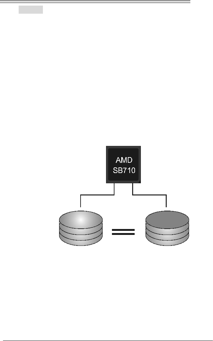
RAID 1:
Every read and write is actually carried out in parallel across 2 disk drives in a RAID 1
array system. The mirrored (backup) copy of the data can reside on the same disk or on
a second redundant drive in the array. RAID 1 provides a hot-standby copy of data if
the active volume or drive is corrupted or becomes unavailable because of a hardware
failure.
RAID techniques can be applied for high-availability solutions, or as a form of
automatic backup that eliminates tedious manual backups to more expensive and less
reliable media.
Features and Benefits
- Drives: Minimum 2, and maximum is 2.
- Uses: RAID 1 is ideal for small databases or any other application that
requires fault tolerance and minimal capacity.
- Benefits: Provides 100% data redundancy. Should one drive fail, the
controller switches to the other drive.
- Drawbacks: Requires 2 drives for the storage space of one drive.
Performance is impaired during drive rebuilds.
- Fault Tolerance: Yes.
Block 1
Block 2
Block 3
Block 1
Block 2
Block 3
Motherboard Manual
20
RAID 1+0:
RAID 1 drives can be stripped using RAID 0 techniques. Resulting in a RAID 1+0
solution for improved resiliency, performance and rebuild performance.
Features and Benefits
- Drives: Minimum 4, and maximum is 6 or 8, depending on the platform.
- Benefits: Optimizes for both fault tolerance and performance, allowing for
automatic redundancy. May be simultaneously used with other RAID
levels in an array, and allows for spare disks.
- Drawbacks: Requires twice the available disk space for data redundancy,
the same as RAID level 1.
- Fault Tolerance: Yes.
Block 1
Block 3
Block 5
Block 2
Block 4
Block 6
Block 1
Block 3
Block 5
Block 2
Block 4
Block 6
A780L3L
21
CHAPTER 5: USEFUL HELP
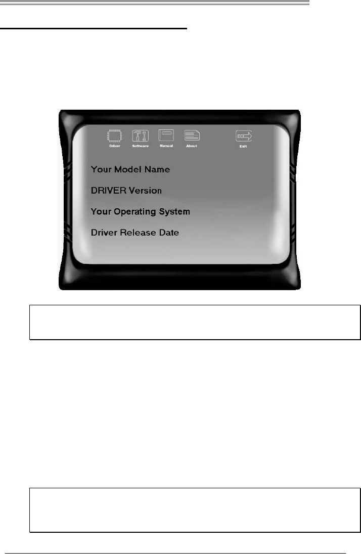
5.1 DRIVER INSTALLATION NOTE
After you installed your operating system, please insert the Fully Setup
Driver CD into your optical drive and install the driver for better system
performance.
You will see the following window after you insert the CD
The setup guide will auto detect your motherboard and operating system.
Note:
If this window didn’t show up after you insert the Driver CD, please use file browser to
locate and execute the file SETUP.EXE under your optical drive.
A. Driver Installation
To install the driver, please click on the Driver icon. The setup guide will
list the compatible driver for your motherboard and operating system.
Click on each device driver to launch the installation program.
B. Software Installation
To install the software, please click on the Software icon. The setup guide
will list the software available for your system, click on each software title
to launch the installation program.
C. Manual
Aside from the paperback manual, we also provide manual in the Driver
CD. Click on the Manual icon to browse for available manual.
Note:
You will need Acrobat Reader to open the manual file. Please download the latest version
of Acrobat Reader software from
http://www.adobe.com/products/acrobat/readstep2.html
Motherboard Manual
22
5.2 SOFTWARE
Installing Software
1. Insert the Setup CD to the optical drive. The drivers installation program
would appear if the Autorun function has been enabled.
2. Select Software Installation, and then click on the respective software
title.
3. Follow the on-screen instructions to complete the installation.
Launching Software
After the installation process, you will see the software icon “eHOT Line” /
“BIOS Update” appears on the desktop. Double-click the icon to launch the
utility.
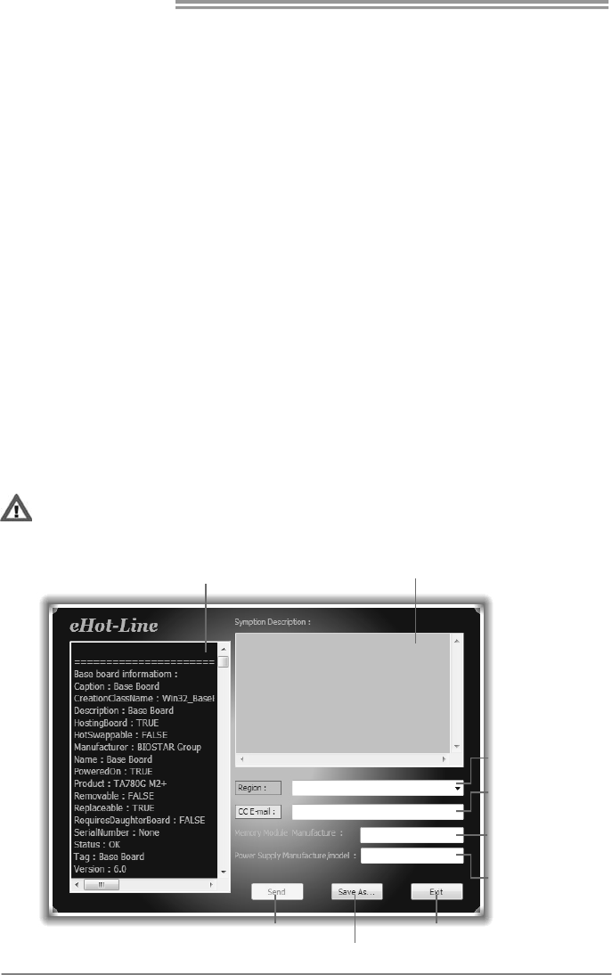
eHot-Line (Optional)
eHot-Line is a convenient utility that helps you to contact with our
Tech-Support system. This utility will collect the system information which is
useful for analyzing the problem you may have encountered, and then send
these information to our tech-support department to help you fix the problem.
Before you use this utility, please set Outlook Express as your default e-mail client application program.
This block will show
the information which
would be collected in
the mail.
Provide the e-mail
address that you would
like to send the copy to.
Provide the name of
the pow e r suppl y
manufacturer and the
model no.
Send the mail out.
Save these in for ma tion to a .txt fil
e
Exit this dialog.
Select your area or
the area close to you.
*
Prov id e the na me of
the memory module
manufacturer.
*
Describe condition
of your system.
*
*
repr es ents impo r t ant
information that you
must provide. Without
this information, you may
not be able to send out
the mail.
A780L3L
23
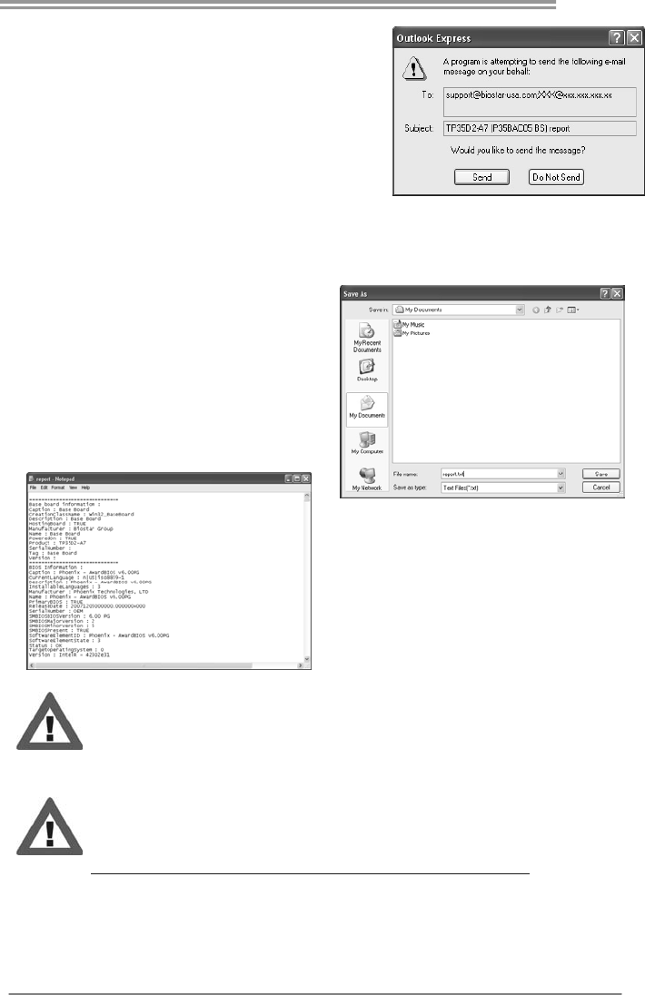
After filling up this information, click “Send”
to send the mail out. A warning dialog would
appear asking for your confirmation; click
“Send” to confirm or “Do Not Send” to cancel.
If you want to save this information to a .txt file, click “Save As…” and then you
will see a saving dialog appears asking you to enter file name.
Enter the file name and then click
“Save”. Your system information
will be saved to a .txt file.
Open the saved .txt file, you will see
your system information including
motherboard/BIOS/CPU/video/
device/OS information. This
information is also concluded in the
sent mail.
We will not share customer’s data with any other third parties,
so please feel free to provide your system information while using
eHot-Line service.
If you are not using Outlook Express as your default e-mail client
application, you may need to save the system information to a .txt file
and send the file to our tech support with other e-mail application.
Go to the following web
http://www.biostar.com.tw/app/en-us/about/contact.php for getting
our contact information.
Motherboard Manual
24
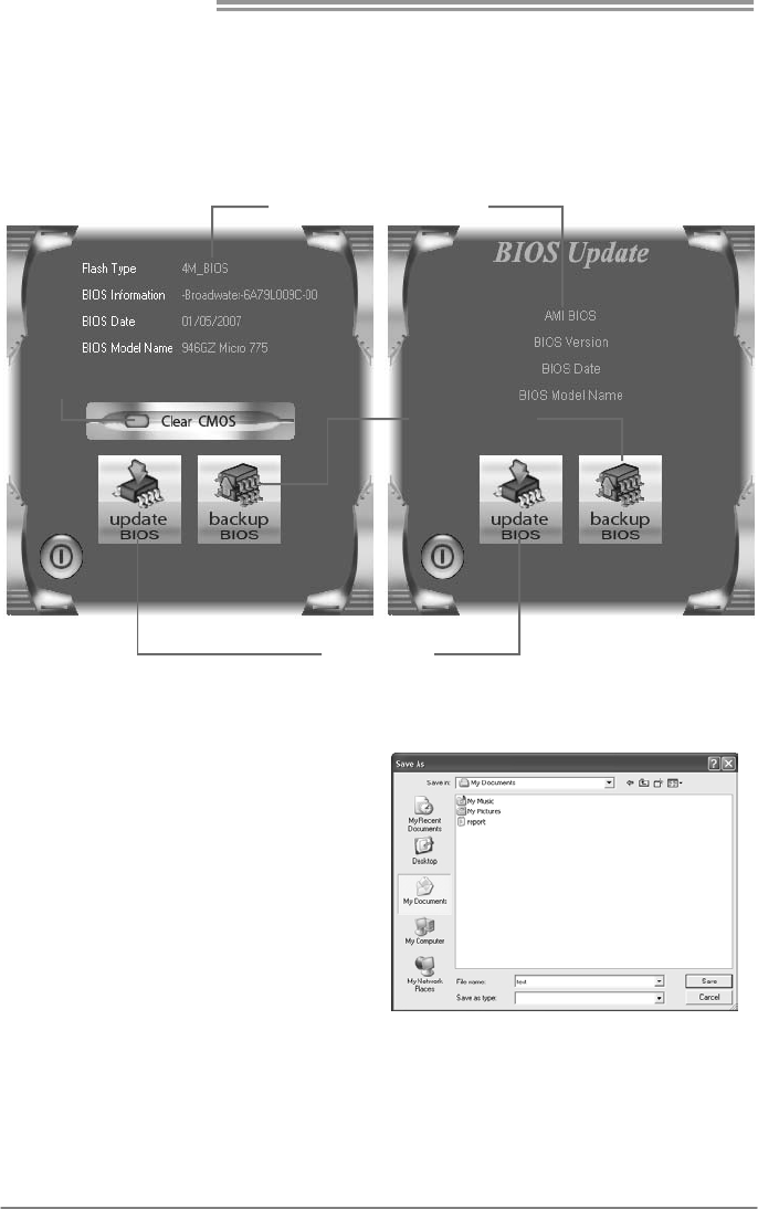
BIOS Update
BIOS Update is a convenient utility which allows you to update your
motherboard BIOS under Windows system.
Update BIOS
with a BIOS file
Clear CMOS function
(Only for AWARD BIOS)
Show current BIOS information
Save current BIOS
to a .bin file
AWARD BIOS AMI BIOS
<Backup BIOS>
Once click on this button, the saving
dialog will show. Choose the
position to save file and enter file
name. (We recommend that the file
name should be English/number
and no longer than 7 characters.)
Then click Save.
A780L3L
25
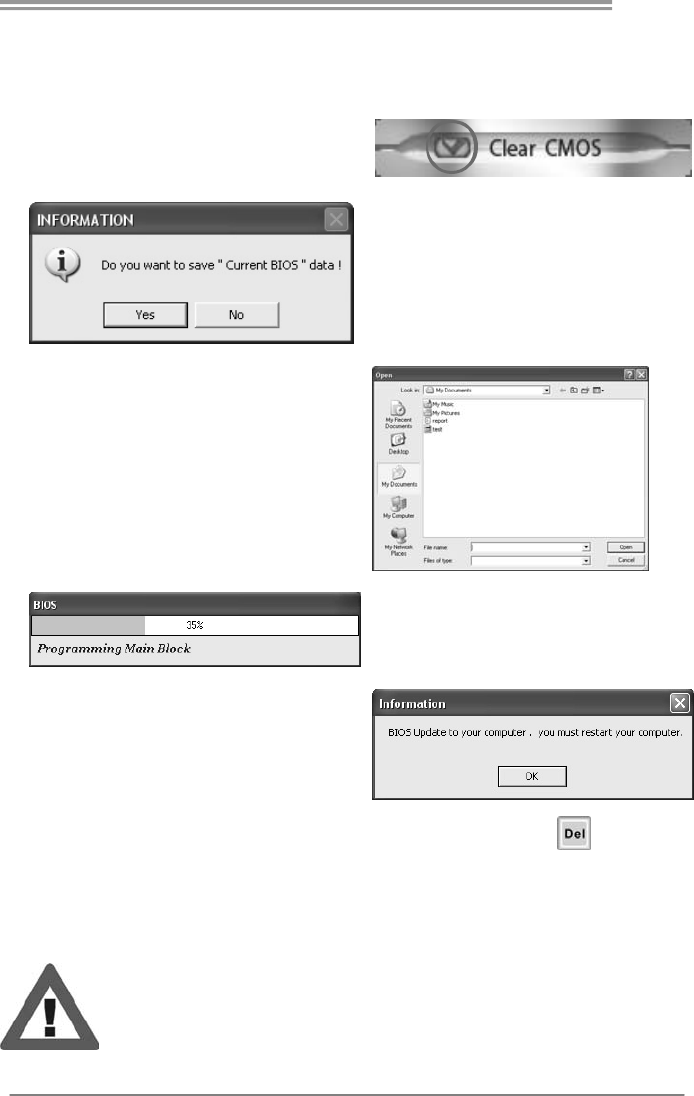
<Update BIOS>
Before doing this, please download the proper BIOS file from the website.
For AWARD BIOS, update BIOS procedure
should be run with Clear CMOS function, so
please check on Clear CMOS first.
Then click Update BIOS button, a
dialog will show for asking you backup
current BIOS. Click Yes for BIOS
backup and refer to the Backup BIOS
procedure; or click No to skip this
procedure.
After the BIOS Backup procedure, the
open dialog will show for requesting the
BIOS file which is going to be updated.
Please choose the proper BIOS file for
updating, then click on Open.
The utility will update BIOS with the
proper BIOS file, and this process may
take minutes. Please do not open any
other applications during this process.
After the BIOS Update process, click on
OK to restart the system.
While the system boots up and the full screen logo shows, press <Delete>
key to enter BIOS setup.
In the BIOS setup, use the Load Optimized Defaults function and then Save and
Exit Setup to exit BIOS setup. BIOS Update is completed.
All the information and content above about the software are subject to be changed
without notice. For better performance, the software is being continuously updated.
The information and pictures described above are for your reference only. The actual
information and settings on board may be slightly different from this manual.

Motherboard Manual
26
5.3 EXTRA INFORMATION
CPU Overheated
If the system shutdown automatically after power on system for
seconds, that means the CPU protection function has been activated.
When the CPU is over heated, the motherboard will shutdown
automatically to avoid a damage of the CPU, and the system may not
power on again.
In this case, please double check:
1. The CPU cooler surface is placed evenly with the CPU surface.
2. CPU fan is rotated normally.
3. CPU fan speed is fulfilling with the CPU speed.
After confirmed, please follow steps below to relief the CPU protection
function.
1. Remove the power cord from power supply for seconds.
2. Wait for seconds.
3. Plug in the power cord and boot up the system.
Or you can:
1. Clear the CMOS data.
(See “Close CMOS Header: JCMOS1” section)
2. Wait for seconds.
3. Power on the system again.
A780L3L
27
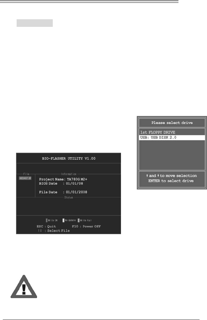
BIO-Flasher
BIO-Flasher is a BIOS flashing utility providing you an easy and simple way to
update your BIOS via USB pen drive or floppy disk.
The BIO-Flasher is built in the BIOS chip. To enter the utility, press <F12>
during the Power-On Self Tests (POST) procedure while booting up.
Updating BIOS with BIO-Flasher
1. Go to the website to download the latest BIOS file for the motherboard.
2. Then, save the BIOS file into a USB pen drive or a floppy disk.
3. Insert the USB pen drive or the floppy disk that contains the BIOS file to the
USB port or the floppy disk drive.
4. Power on or reset the computer and then
press <F12> during the POST process.
A select dialog as the picture on the right
appears.
Select the device contains the BIOS file and
press <Enter> to enter the utility.
5. The utility will show the BIOS
files and their respective
information. Select the proper
BIOS file and press <Enter>
then <Y> to perform the BIOS
update process.
6. After the update process, the utility will ask you to reboot the system.
Press <Y> to proceed. BIOS update completes.
z This utility only allows storage device with FAT32/16 format and single
partition.
z Shutting down or resetting the system while updating the BIOS will lead to
system boot failure.
Motherboard Manual
28
5.4 TROUBLESHOOTING
Probable Solution
1. There is no power in the system.
Power LED does not shine; the
fan of the power supply does not
work
2. Indicator light on keyboard does
not shine.
1. Make sure power cable is
securely plugged in.
2. Replace cable.
3. Contact technical support.
System is inoperative. Keyboard lights
are on, power indicator lights are lit,
and hard drives are running.
Using even pressure on both ends of
the DIMM, press down firmly until the
module snaps into place.
System does not boot from a hard disk
drive, but can be booted from optical
drive.
1. Check cable running from disk to
disk controller board. Make sure
both ends are securely plugged
in; check the drive type in the
standard CMOS setup.
2. Backing up the hard drive is
extremely important. All hard
disks are capable of breaking
down at any time.
System only boots from an optical
drive. Hard disks can be read,
applications can be used, but system
fails to boot from a hard disk.
1. Back up data and applications
files.
2. Reformat the hard drive.
Re-install applications and data
using backup disks.
Screen message shows “Invalid
Configuration” or “CMOS Failure.”
Review system’s equipment. Make sure
correct information is in setup.
System cannot boot after user installs a
second hard drive.
1. Set master/slave jumpers
correctly.
2. Run SETUP program and select
correct drive types. Call the drive
manufacturers for compatibility
with other drives.

A780L3L
29
This page is intentionally left blank.

Motherboard Manual
30
APPENDIX: SPEC IN OTHER LANGUAGES
GERMAN
Spezif ikationen
CPU
Sockel AM3
AMD Sempron / Athlon II / Phenom II
Prozessoren
(Maximales Watt: 95W)
Die AMD 64-Architektur unterstützt eine 32-Bit- und
64-Bit-Datenverarbeitung
Unterstützt Hyper Transport 3.0
FSB Unterstützt HyperTransport 3.0 mit einer
Bandbreite von bis zu 3.2 GT/s
Chipsatz AMD RS780L
AMD SB710
Super E/A
ITE8721
Biet et die h äufig verwendeten alten Super
E/A-Funktionen.
Low Pin Count-Schnittstelle
Umgebungskontrolle,
Hardware-Überwachung
"Smart Guardian"-Funktion von ITE
Arbeitsspeich
er
DDR3 DIMM-Steckplätze x 2
Max. 8GB Arbeitsspeicher
Jeder DIMM unterstützt 512MB/
1GB/2GB/4GB DDR3.
Dual-Kanal DDR3 Speichermodul
Unterstützt DDR3 800 / 1066 / 1333
registrierte DIMMs. ECC DIMMs werden nicht
unterstützt.
Grafik Integrierter AMD RS780L-Chipsatz
Max. 512MB gemeinsam benutzter Videospeicher
Unterstützt DVI/HDCP
IDE Integ riert er IDE-Controller
Ultra DMA 33 / 66 / 100 / 133 Bus Master- Modus
Unterstützt PIO-Modus 0~4,
SATA Integrierter Serial ATA-Controller
Datentransferrate bis zu 3 Gb/s
Konform mit der SATA-Spezifikation Version 2.0.
LAN Realtek RTL 8103EL
10 / 100 Mb/s Auto-Negotiation
Halb-/ Vollduplex-Funktion
HD
Audio-Unters
tützung
ALC662
5.1-Kanal-Audioausgabe
Unterstützt High-Definition Audio
PCI Express Gen2 x16 Steckplatz x1
Steckplätze
PCI-Steckplatz x2

A780L3L
31
Spezif ikationen
Diskettenlaufwerkanschluss x1 Jeder Anschluss unterstützt 2 Diskettenlaufwerke
IDE-Anschluss x1 Jeder Anschluss unterstützt 2 IDE-Laufwerke
SATA-Anschluss x4 Jeder Anschluss unterstützt 1 SATA-Laufwerk
Fronttafelanschluss x1 Unterstützt die Fronttafelfunktionen
Front-Audioanschluss x1 Unterstützt die Fronttafel-Audioanschlussfunktion
S/PDIF Ausgangsanschluss x1 Unterstützt die digitale Audioausgabefunktion
CPU-Lüfter-Sockel x1
CPU-Lüfterstromversorgungsanschluss (mit Smart
Fan-Fun ktio n )
System-Lüfter-Sockel x1 System-Lüfter-Stromversorgungsanschluss
"CMOS löschen"-Sockel x1
USB-Anschluss x2
Jeder Anschluss unterstützt 2
Fronttafel-USB-Anschlüsse
Stromanschluss (24-polig) x1
Stromanschluss (4-polig ) x1
Druckeranschluss Anschluss x1 Jeder Anschluss unterstützt 1 Druckeranschluss
Onboard-Ans
chluss
Serieller Anschluss x1
Rückseiten-E
/A
PS/2-Tastatur x1
PS/2- Maus x1
VGA-Anschluss x1
LAN-Anschluss x1
USB-Anschluss x4
Audioanschluss x3
DVI-Anschluss x1
Platinengröß
e
182 mm (B) X 235 mm (L)
Sonderfunkti
onen
Unterstützt RAID 0 / 1 / 1+0
OS-Unterstü
tzung Windows XP / Vista / 7
Biostar behält sich das Recht vor, ohne Ankündigung
die Unterstützung für ein Betriebssystem
hinzuzufügen oder zu entfernen.

Motherboard Manual
32
FRENCH
SPEC
UC
Sockel AM3
Processeurs AMD Sempron / Athlon II /
Phenom II
(Watt maximum : 95W)
L'architecture AMD 64 permet le calcul 32 et 64 bits
Prend en charge Hyper Transport 3.0
Bus frontal Prend en charge Hyper Transport 3.0
jusqu'à une bande passante de 3.2 GT/s
Chipset AMD RS780L
AMD SB710
Super E/S
ITE 8721
Fournit la fonctionnalité de Super E/S
patrimoniales la plus utilisée.
Interface à faib le co mpte de b roches
Initiatives de contrôle environnementales,
Mon iteur d e mat ér iel
Fonction "Gardien intelligent" de l'ITE
Mémoire
principale
Fentes DDR3 DIMM x 2
Capacité mémo ire max imale de 8 Go
Chaque DIMM prend en charge des DDR3
de 512Mo/1Go/2Go/4Go
Module d e mémo ire DDR3 à mod e à double voie
Prend en charge la DDR3 800 / 1066 / 1333
Les DIMM à registres et DIMM avec code correcteurs
d'erreurs ne sont pas prises en charge
Graphiques Integré dans la chipset AMD RS780L Mémoire vidéo partagée maximale de 512 Mo
Prise en charge DVI/HDCP
IDE Contrôleur IDE intégré Mode principale de Bus Ultra DMA 33 / 66 / 100 / 133
Prend en charge le mode PIO 0~4,
SATA
Contrôleur Serial ATA
int égr é
Taux de transfert jusqu'à 3 Go/s.
Conforme à la spéc if icat ion SATA Vers ion 2.0
LAN Realtek RTL 8103EL 10 / 100 Mb/s négociation automatique
Half / Full duplex capability
Prise en
charge
audio HD
ALC662 Sortie aud io à 5.1 voies
Prise en charge de l'audio haut e définition
Fente PCI Express Gen2 x16 x1
Fentes
Fente PCI x2
Connecteur de disquette x1 Chaque connector prend en charg e 2 lecteurs de
disquettes
Connecteur
embarqué
Connecteur IDE x1 Chaque connecteur prend en charge 2 périphériques
IDE

A780L3L
33
SPEC
Connecteur SATA x4 Chaque connecteur prend en charg e 1 périphérique
SATA
Connecteur du panneau avant x1 Prend en charge les équipements du panneau avant
Connecteur Audio du panneau avant x1 Prend en charge la fonction audio du panneau avant
Connecteur de sortie S/PDIF x1 Prend en charge la fonction de sortie audio numérique
Embase de ventilateur UC x1 Alimentation électrique du ventilateur UC (avec
fonction de ventilateur intelligent)
Embase de ventilateur système x1 Alimentation électrique du ventilateur système
Embase d'effacement CMOS x1
Connecteur USB x2 Chaque connecteur prend en charge 2 ports USB de
panneau avant
Connecteur d'aliment ation x1
(24 broches)
Connecteur d'aliment ation x1
(4 broch es)
Connecteur de Port d'imprimante x1 Chaque connector prend en charge 1 Port
d'imprimante
Connecteur de Port série x1
E/S du
panneau
arrière
Clavier PS/2 x1
Souris PS/2 x1
Port VGA x1
Port LAN x1
Port USB x4
Fiche audio x3
Port DVI x1
Dimension
s de la
cart e
182 mm (l) X 235 mm (H)
Fonctionnal
ités
spéciales
Prise en charge RAID 0 / 1 / 1+0
Support SE
Windows XP / Vista / 7 Biostar se réserve le droit d'ajouter ou de supprimer le
support de SE avec ou sans préavis.

Motherboard Manual
34
ITALIAN
SPECIFICA
CPU
Sockel AM3
Processori AMD Sempron / Athlon II /
Phenom II
(Watt massimo: 95W)
L’architettura AMD 64 abilita la co mputazione 32
e 64 bit
Supporto di Hyper Transport 3.0
FSB Supporto di HyperTransport 3.0 fino a
3.2 GT/s di larghezza di banda
Chipset AMD RS780L
AMD SB710
Super I/O
ITE 8721
Fornisce le funzionalità legacy Super
I/O usate più comunemente.
Interfaccia LPC (Low Pin Count)
Funzioni di controllo dell’ambiente:
Monitoraggio hardware
Funzione "Smart Guardian" di ITE
Memoria
principale
Alloggi DIMM DDR3 x 2
Capacità massima della memoria 8GB
Ciascun DIMM supporta DDR3
512MB/1GB/2GB/4GB
Modulo di memoria DDR3 a canale doppio
Supporto di DDR3 800 / 1066 / 1333
DIMM registrati e DIMM ECC non sono supportati
Grafica Integrata nel Chipset AMD RS780L La memoria video condivisa massima è di 512 MB
Supporto DVI/HDCP
IDE Controller IDE integrato
Modalità Bus Master Ultra DMA 33 / 66 / 100 /
133
Supporto modalità PIO Mode 0-4
SATA Controller Serial ATA integrato Velocità di trasferimento dei dati fino a 3 Gb/s.
Compatibile specifiche SATA Versione 2.0.
LAN Realtek RTL 8103EL Negoziazione automatica 10 / 100 Mb/s
Capacità Half / Full Duplex
Supporto
audio HD ALC662 Uscita audio 5.1 canali
Supporto audio High-Definition (HD)
Alloggio PCI Express Gen2 x16 x1
Alloggi Alloggio PC I x2
Connettore floppy x1 Ciascun connettore supporta 2 unità Floppy
Connettore IDE x1 Ciascun connettore supporta 2 unità IDE
Connettore SATA x4 Ciascun connettore supporta 1 unità SATA
Connettori
su scheda
Connettore pannello frontale x1 Supporta i servizi del pannello frontale

A780L3L
35
SPECIFICA
Connettore audio frontale x1 Supporta la funzione audio pannello frontale
Connettore output S/PDIF x1 Supporta la funzione d’output audio digitale
Collettore ventolina CPU x1 Alimentazione ventolina CPU (con funzione Smart
Fan)
Collettore ventolina sistema x1 Alimentazione ventolina di sistema
Collettore cance llaz ione CMOS x1
Connettore USB x2 Ciascun connettore supporta 2 porte USB
pannello frontale
Connettore alimentazione x1
(24 pin)
Connettore alimentazione x1
(4 pin)
Connettore Porta stampante x1 Ciascun connettore supporta 1 Porta stampante
Connettore Porta seriale x1
I/O
pannello
posteriore
Tas t iera PS /2 x1
Mouse PS/2 x1
Porta VGA x1
Porta LAN x1
Porta USB x4
Connettore audio x3
Porta DVI x1
Dimension
i scheda
182 mm (larghezza) x 235 mm
(altezza)
Caratterist
iche
speciali
Supporto RAID 0 / 1 / 1+0
Sistemi
operativi
supportati
Windows XP / Vista / 7
Biostar si riserva il diritto di aggiungere o
rimuovere il supporto di qualsiasi sistema
operativo senza preavviso.

Motherboard Manual
36
SPANISH
Especificación
CPU
Conector AM3
Procesadores AMD Sempron / Athlon II /
Phenom II
(Vatio máx imo: 95W)
La arquitectura AMD 64 permite el procesado de 32 y
64 bits
Soporta las tecnologías Hyper Transport 3.0
FSB Admite HyperTransport 3.0 con un ancho
de banda de hasta 3.2 GT/s
Conjunto
de chips
AMD RS780L
AMD SB710
Súper E/S
ITE 8721
Le ofrece las funcionalidades heredadas
de uso más común Súper E/S.
Interfaz de cuenta Low Pin
In ic iat ivas de control d e entorno,
Monitor hardware
Función "Guardia inteligente" de ITE
Memoria
principal
Ranuras DIMM DDR3 x 2
Capacidad máxima de memoria de 8GB
Cada DIMM admite DDR de
512MB/1GB/2GB/4GB
Módulo de memoria DDR3 de canal Doble
Admite DDR3 de 800 / 1066 / 1333
No admite DIMM registrados o DIMM compatibles con
ECC
Gráficos Integrados en el conjunto de chips AMD
RS780L
Memoria máxima de vídeo compartida de 512 MB
Admite DVI/HDCP
IDE Controlador IDE integrado Modo bus maestro Ultra DMA 33 / 66 / 100 / 133
Soporte los Modos PIO 0~4,
SATA Controlador ATA Serie Integrado Tasas de transferencia de hasta 3 Gb/s.
Compat ib le con la versión SATA 2.0.
Red Local Realtek RTL 8103EL Negociación de 10 / 100 Mb/s
Funciones Half / Full dúplex
Soporte de
sonido HD ALC662 Salida de sonido de 5.1 canales
Soporte de sonido Alta Definición
Ranura PCI Express Gen2 x16 X1
Ranuras Ranura PCI X2
Conector disco flexible X1 Cada conector soporta 2 unidades de disco flexible
Conector IDE X1 Cada conector soporta 2 dispositivos IDE
Conector SATA X4 Cada conector soporta 1 dispositivos SATA
Conector de p anel f rontal X1 Soporta instalaciones en el p anel frontal
Conectores
en placa
Conector de sonido frontal X1 Soporta funciones de sonido en el panel frontal

A780L3L
37
Especificación
Conector de salida S/PDIF X1 Soporta función de salida de sonido digital
Cabecera de ventilador de CPU X1 Fuente de alimentación de ventilador de CPU (con
función Smart Fan)
Cabecera de ventilador de sistema X1 Fuente de alimentación de ventilador de sistema
Cabecera de borrado de CMOS X1
Conector USB X2 Cada conector soporta 2 puertos USB frontales
Conector de alimentación X1
(24 patillas)
Conector de alimentación X1
(4 patillas)
Conector Puerto de impresora X1 Cada conector soporta 1 Puerto de impresora
Conector Puerto serie X1
Panel
trasero de
E/S
Tec l ado PS /2 X 1
Ratón PS/2 X1
Puerto VGA X1
Puerto de red local X1
Puerto USB X4
Conector de sonido X3
Puerto DVI X1
Ta maño d e
la placa 182 mm. (A) X 235 Mm. (H)
Funciones
especiales Admite RAID 0 / 1 / 1+0
Soporte de
sistema
operativo
Windows XP / Vista / 7 Biostar se reserva el derecho de añadir o retirar el
soporte de cualquier SO con o sin aviso previo.

Motherboard Manual
38
PORTUGUESE
ESPECIFICAÇÕES
CPU
Sockel AM3
Processadores AMD Sempron / Athlon II /
Pheno m II
(Watt máximo: 95W)
A arquitectura A MD 64 permite uma co mputação de
32 e 64 bits
Suporta as tecnolog ias Hyper Transport 3.0
FSB Suporta a tecnologia HyperTransport 3.0
com uma largura de banda até 3.2 GT/s
Chipset AMD RS780L
AMD SB710
Especificaç
ão Super
I/O
ITE 8721
Proporciona as funcionalidades mais
utilizadas em termos da especificação
Super I/O.
Interface LPC (Low Pin Count).
In ic iat ivas para contro lo do ambiente
Monitorização do hardware
Função "Smart Guardian" da ITE
Memória
principal
Ranhuras DIMM DDR3 x 2
Capacidade máx ima d e memória: 8GB
Cada módulo DIMM suporta uma
memória DDR3 de 512MB/
1GB/2GB/4GB
Módulo de memória DDR3 de canal duplo
Suporta módulos DDR3 800 / 1066 / 1333
Os módulos DIMM registados e os DIMM ECC não são
suportados
Placa
gráfica Integrada no chipset AMD RS780L Memória de vídeo máxima partilhada: 512 MB
Suporta as funções DVI/HDCP
IDE Controlador IDE integrado Modo Bus master Ultra DMA 33 / 66 / 100 / 133
Suporta o modo PIO 0~4,
SATA Controlador Serial ATA integrado Velocidades de transmissão de dados até 3 Gb/s.
Compatibilidade com a especificação SATA versão 2.0.
LAN Realtek RTL 8103EL Auto negociação de 10 / 100 Mb/s
Capacidade semi/full-duplex
Suporte
para áudio
de alta
definição
ALC662 Saída de áudio de 5.1 canais
Suporta a especificação High-Definition Audio
Ranhura PCI Express Gen2 x16 x1
Ranhuras Ranhura PCI x2
Conector da unidade de disquetes x1 Cada conector suporta 2 unidades de disquetes
Conector IDE x1 Cada conector suporta 2 dispositivos IDE
Conector SATA x4 Cada conector suporta 1 dispositivo SATA
Conectores
na placa
Conector do painel frontal x1 Para suporte de várias funções no painel frontal

A780L3L
39
ESPECIFICAÇÕES
Conector de áudio frontal x1 Suporta a função de áudio no painel frontal
Conector de saíd a S/PD IF x1 Suporta a saída de áudio digital
Conector da ventoinha da CPU x1 Alimentação da ventoinha da CPU (com a função
Smart Fan)
Conector da ventoinha do sistema x1 Alimentação da ventoinha do sistema
Conector para limpeza do CMOS x1
Conector USB x2 Cada conector suporta 2 portas USB no painel frontal
Conector de alimentação x1
(24 pinos)
Conector de alimentação x1
(4 p inos)
Conector da para impressora x1 Cada conector suporta 1 Porta para impressora
Conector da Porta série x1
Entradas/S
aídas no
painel
traseiro
Tec l ado PS /2 x 1
Rato PS/2 x1
Porta VGA x1
Porta LAN x1
Porta USB x4
Tomada de áudio x3
Porta DVI x1
Tamanho
da placa 182 mm (L) X 235 mm (A)
Característi
cas
especiais
Suporta as funções RAID 0 / 1 / 1+0
Sistemas
operativos
suportados
Windows XP / Vista / 7
A Biostar reserva-se o direito de adicionar ou remover
suporte para qualquer sistema operativo com ou sem
av iso prévio.

Motherboard Manual
40
POLISH
SPEC
Procesor
Sockel AM3
AMD Sempron / Athlon II / Phenom II
Procesory
(Maksymalny Watt: 95W)
Architektura AMD 64 umożliwia przetwarzanie 32 i 64
bitowe
Obsługa Hyper Transport 3.0
FSB Obsługa HyperTransport 3.0 o szerokości
pasma do 3.2 GT/s
Chipset AMD RS780L
AMD SB710
Pamięć
główna
Gniazda DDR3 DIMM x 2
Maks. wielkość pamięci 8GB
Każde gniazdo DIMM obsługuje moduły
512MB/1GB/2GB/4GB DDR3
Modu ł pamięci DDR3 z trybem podwójnego kanału
Obsługa DDR3 800 / 1066 / 1333
Brak obsługi R egistered DIMM oraz ECC DIMM
Super I/O
ITE 8721
Zapewnia najbardziej powszechne
funkcje Super I/O.
Interfejs Low Pin Count
Funkcje kontroli warunków pracy,
Mon itor H/W
Funkcja ITE "Smart Guard ian"
Grafika Zintegrowana w chipsecie AMD RS780L
Maks. wielkość współdz ielon ej pamięci video wynosi
512 MB
Obsługa DVI/HDCP
IDE Zintegrowany kontroler IDE Ultra DMA 33 / 66 / 100 / 133 Tryb Bus Master
obsługa PIO tryb 0~4,
SATA Zintegrowany kontroler Serial ATA Transfer danych do 3 Gb/s.
Zgodność ze specyfikacją SATA w wersji 2.0.
LAN Realtek RTL 8103EL 10 / 100 Mb/s z automatyczną negocjacją szybkości
Działan ie w trybie połowicznego/pełnego dupleksu
Obsługa
audio HD ALC662 5.1 kanałowe wyjście audio
Obsługa High-Defin ition Aud io
Gniazdo PCI Express Gen2 x16 x1
Gniazda Gniazdo PCI x2
Złącze napędu dyskietek x1 Każde złącze obsługuje 2 napędy dyskietek
Złącze IDE x1 Każde złącze obs ługuje 2 urządzenia IDE
Złącze SATA x4 Każde złącze obs ługuje 1 urządzenie SATA
Złącza
wbudowan
e
Złącze panela przedniego x1 Obsługa elementów panela przedniego

A780L3L
41
SPEC
Przednie złącze audio x1 Obsługa funkcji audio na panelu przednim
Złącze wyjścia S/PDIF x1 Obsługa funkcji cyfrowego wyjścia audio
Złącze główkowe wentylatora procesora
x1 Zasilanie wentylatora procesora (z funkcją Smart Fan)
Złącze głó wkowe wentylatora
systemowego x1 Zasilanie wentylatora systemowego
Złącze głó wkowe kasowania CMOS x1
Złącze USB x2 Każde złącze obs ługuje 2 porty USB na panelu
przednim
Złącze zasilania (24 pinowe) x1
Złącze zas ilania (4 p ino we) x1
Złącze Port drukarki x1 Każde złącze obsługuje 1 Port drukarki
Złącze Port szeregowy x1
Back Panel
I/O
Klawiatura PS/2 x1
Mysz PS /2 x 1
Port VGA x1
Port LAN x1
Port USB x4
Gniazdo audio x3
Port DVI x1
Wymiary
płyty 182 mm (S) X 235 mm (W)
Funkcje
specjalne Obsługa RAID 0 / 1 / 1+0
Obsluga
systemu
operacyjne
go
Windows XP / Vista / 7
Biostar zastrzega sobie prawo dodawania lub
odwoływania obsług i dowo ln ego systemu
operacyjnego bez powiado mienia.

Motherboard Manual
42
RUSSIAN
СПЕЦ
CPU
(централь
ный
процессор
)
Гнездо AM3
Процессоры AMD Sempron / Athlon II /
Phenom II
(Максимал ьн ый ватт: 95W)
Архитектур а AMD 64 разрешать обработка данных
на 32 и 64 бит
Поддержка Hyp er Transport 3.0
FSB Поддержка HyperTransport 3.0 с
пропускной способностью до 3.2 GT/s
Набор
микросхем
AMD RS780L
AMD SB710
Основная
память
Слоты DDR3 DIMM x 2
Максимальная ёмкость памяти 8ГБ
Каждый модуль DIMM поддерживает
512МБ /1ГБ/2ГБ/4ГБ DDR3
Модуль памяти с двухканальным режимом DDR3
Поддержка DDR3 800 / 1066 / 1333
Не поддерживает зарегистрированные модули
DIMM and ECC DIMM
Super I/O
ITE 8721
Обеспечивает наиболее используемые
действующие фун кц иональны е
возможности Super I/O.
Интерфейс с низким количеством выводов
Инициативы по охране окружающей среды,
Аппаратный монитор
Функция ITE "Smart Guardian" (Интеллектуальная
защита)
Графика Встроенная в набор микросхем AMD
RS780L
Максимальная совместно используемая вид ео
память составляет 512 МБ
Поддержка DVI/HDCP
IDE Встроенное устройство управл ения
встроенными интерфейсами устройств
Режим "хозяина" шины Ultra DMA 33 / 66 / 100 / 133
Поддержка режима PIO 0~4,
SATA Встроенное последоват ельное
устройство управления ATA
скорость передачи данных до 3 гигабит/с.
Соответствие спецификации SATA версия 2.0.
Локальная
сеть Realtek RTL 8103EL Автоматическое согласование 10 / 100 Мб /с
Частичная / полная дуплексная способность
Звуко вая
поддержка
жесткого
диска
ALC662 Звуко вая поддержка High-Def inition
5.1канальный звуковой выход
Слот PCI Express Gen2 x16 x1
Слоты Слот PCI x2
Разъём НГМД x1
Каждый разъём поддерживает 2 накопителя на
гибких магнитных дисках
Разъём IDE x1 Каждый разъём поддерживает 2 встроенных
интерфейса накопителей
Встроенны
й разъём
Разъём SATA x4 Каждый разъём поддерживает 1 устройство SATA

A780L3L
43
СПЕЦ
Разъём на лицевой панели x1 Поддержка устройств на лицевой панели
Входной звуковой разъём x1 Поддержка звуко вых функций на лицевой панели
Разъём вывода для S/PDIF x1 Поддержка вывода цифровой звуковой фун кц ии
Контактирующее приспособление
вентил ятора центрального
процессора x1
Источник питания для вентилятора центрального
процессора (с фун кцией интеллектуального
вентил ятора)
Контактирующее приспособление
вентил ятора системы x1
Источник питания для вентилятора системы
Открытое контактирующее
приспособление CMOS x1
USB-разъём x2
Каждый разъём поддерживает 2 USB-порта на
лицевой панели
Разъем питания (24 вывод) x1
Разъем питания (4 вывод) x1
Разъём Порт подключения
принтера x1
Каждый разъём поддерживает 1 Порт подключения
принтера
Разъём Последовательный порт x1
Задняя
панель
средств
ввода-выв
ода
Клавиатура PS/2 x1
Мышь PS/2 x1
Порт VGA x1
Порт LAN x1
USB-порт x4
Гнездо для подключения
наушнико в x3
Порт DVI x1
Размер
панели 182 мм (Ш) X 235 мм (В)
Специальн
ые
техническ
ие
характери
стики
Поддержка RAID 0 / 1 / 1+0
Поддержк
а OS Windows XP / Vista / 7
Biostar сохраняет за собой право добавлять или
удалять средства обеспечения для OS с или без
предварительного уведомления.

Motherboard Manual
44
ARABIC
تﺎﻔﺻاﻮﻤﻟا
ﺔﻴﻨﻘﺗ ﻦﻜﻤﺗAMD 64 ﺔﻋﺮﺴﺑ ﺔﻴﺑﻮﺳﺎﺤﻟا تﺎﻴﻠﻤﻌﻟا ءاﺮﺟإ 32 و64 ﺖﺑ
ﺔﻴﻨﻘﺗ ﻢﻋﺪﺗHyper Transport و 3.0
ﺲﺒﻘﻡAM3
تﺎﺠﻟﺎﻌﻡAMD Sempron / Athlon II
Phenom II
(طاو ىﻮﺼﻗ: 95و)
ةﺪﺡو ﺔﺠﻟﺎﻌﻤﻟا
ﺔیﺰآﺮﻤﻟا
ﺔﻴﻨﻘﺗ ﻢﻋﺪﺗHyperTransport ی ددﺮﺘﺑ ﻰﻟإ ﻞﺼ3.0 3.2 GT/s
ﻞﻗﺎﻨﻟا ﻲﻣﺎﻣﻷا ﻲﺒﻥﺎﺠﻟا
AMD RS780L
AMD SB710
ﺔﻋﻮﻤﺠﻡ ﺢﺋاﺮﺸﻟا
ﺔﻴﻨﻘﺗ ﻢﻋﺪﺗLow Pin Count Interface
ﺔﺌﻴﺒﻟا ﻲﻓ ﻢﻜﺤﺘﻟا ﻞﺋﺎﺳو:
ةﺰﻬﺟﻷا ﺔﻟﺎﺡ ﺔﻓﺮﻌﻤﻟ ﺐﻗاﺮﻡ
ﺔﻔﻴﻇو"Smart Guard ian" ﻦﻡ ITE
ITE 8721
ﺔﻔﻴﻇو ﺮﻓﻮﺗSuper I/O ًﺎ ﻡ ا ﺪ ﺨ ﺘﺳ ا ﺮﺜآﻷا .
Super I/O
ةﺮآاذ ةﺪﺡوDDR3 ﻘﻟا ﺔﺟودﺰﻡةﺎﻨ
عﻮﻥ ﻦﻡ ةﺮآاﺬﻟا ﻢﻋﺪﺗDDR3 تﺎﻌﺳ 800 / 1066 / 1333ﺖیﺎﺑ ﺎﺠﻴﻡ
ةﺮآاﺬﻟا ﻖﺋﺎﻗر ﻢﻋﺪﺗ ﻻDIMM ﻊﻡ ﻖﻓاﻮﺘﺗ ﻻ ﻲﺘﻟا ﻚﻠﺗو ECC
ﺔﺤﺘﻓDDR3 DIMM دﺪﻋ2
ىﻮﺼﻗ ةﺮآاذ ﺔﻌﺳ8 ﺖیﺎﺑ ﺎﺠﻴﺟ
ﺔﺤﺘﻓ ﻞآ ﻢﻋﺪﺗDIMM عﻮﻥ ﻦﻡ ةﺮآاذ ﻢﻋﺪﺗ DDR3 ﺔﻌﺳ /512 ﺖیﺎﺑ ﺎﺠﻴﻡ
و1/و 2/و 4 ﺎﺠﻴﺟﺖیﺎﺑ
ةﺮآاﺬﻟا ﺔﻴﺴﻴﺋﺮﻟا
ﻰﺼﻗأ ﺔﻌﺳ ةﺮآاﺬﻟ ﻮیﺪﻴﻔﻟا ﺔآﺮﺘﺸﻤﻟا 512 ﺎﺠﻴﻡ ﺖیﺎﺑ
ﺔﻴﻨﻘﺗ ﻢﻋﺪﺗDVI/HDCP
ﻖﺋﺎﻗر ﻲﻓ ﺔﺠﻡﺪﻡ AMD RS780L
ﺔﻗﺎﻄﺑ تﺎﻡﻮﺳﺮﻟا
ﺔﻴﻨﻘﺘﺑ ﻞﻗﺎﻥUltra DMA 33 / 66 / 100 / 133ﻲﺴﻴﺋر ﻊﺿو
ﻊﺿو ﻢﻋدPIO Mode 0~4
ﻢﻜﺤﺘﻡIDE ﻞﻡﺎﻜﺘﻡ ﺬﻔﻨﻡ IDE
ﻞﻘﻥ ﻥﺎﻴﺒﻟاتﺎ تﺎﻋﺮﺴﺑ ﻞﺼﺗ ﻰﻟإ 3 ﺖﺑﺎﺠﻴﺟ/ﺔﻴﻥﺎﺙ.
ﺔﻘﺑﺎﻄﻡ تﺎﻔﺹاﻮﻤﻟ SATA راﺪﺹﻹا 2.0.
ﻢﻜﺤﺘﻡ Serial ATA ﻞﻡﺎﻜﺘﻡ
SATA
ﻲﺋﺎﻘﻠﺗ ضوﺎﻔﺗ10/100 ﺖیﺎﺑ ﺎﺠﻴﻡ /ﺔﻴﻥﺎﺙ
ﺔﻴﻥﺎﻜﻡإ ﻞﻘﻨﻟا جودﺰﻤﻟا ﻞﻡﺎﻜ ﻟا/ﻲﻔﺼﻨﻟا
Realtek RTL 8103EL
ﺔﻜﺒﺵ ﺔﻴﻠﺥاد
5.1 تاﻮﻨﻗ جﺮﺨﻟ تﻮﺼﻟا
ﻒیﺮﻌﺘﻟا ﻲﻟﺎﻋ تﻮﺼﻟا ﺔﻴﻨﻘﺗ ﻢﻋﺪﺗﻦﻡ
ALC662
ﻢﻋد تﻮﺼﻟا ﻲﻟﺎﻋ
ﻒیﺮﻌﺘﻟا
ﺔﺤﺘﻓx16 PCI Express Gen2 دﺪﻋ1
ﺔﺤﺘﻓPCI دﺪﻋ2
تﺎﺤﺘﻔﻟا
ﺔﻥﺮﻤﻟا صاﺮﻗﻸﻟ ﻦﻴآﺮﺤﻡ ﻢﻋﺪی
ﺔﻥﺮﻡ صاﺮﻗأ كﺮﺤﻡ ﺬﻔﻨﻡ دﺪﻋ1
ةﺰﻬﺟأ ﻦﻡ ﻦﻴﻨﺙا ﺬﻔﻨﻡ ﻞآ ﻢﻋﺪیIDE
ﺬﻔﻨﻡIDE دﺪﻋ1
ةﺰﻬﺟأ ﻦﻡ ﺪﺡاو ﺬﻔﻨﻡ ﻞآ ﻢﻋﺪیSATA
ﺬﻔﻨﻡ SATA دﺪﻋ4
ﺬﻓﺎﻨﻤﻟا ﻰﻠﻋ ﺢﻄﺳ
ﺔﺡﻮﻠﻟا
A780L3L
45
تﺎﻔﺻاﻮﻤﻟا
ﺔﻴﻡﺎﻡﻷا ﺔﺡﻮﻠﻟا تاﺰﻴﻬﺠﺗ ﻢﻋﺪی
ﺔﻴﻡﺎﻡﻷا ﺔﺡﻮﻠﻟا ﺬﻔﻨﻡ دﺪﻋ1
ﺔﻴﻡﺎﻡﻷا ﺔﺡﻮﻠﻟﺎﺑ تﻮﺼﻟا ﺔﻔﻴﻇو ﻢﻋﺪی
ﻲﻡﺎﻡﻷا تﻮﺼﻟا ﺬﻔﻨﻡ دﺪﻋ1
ﻢﻋﺪﻳ ﺔﻔ ﻴﻇو جﺮﺧ تﻮﺼﻟا ﻲﻤﻗﺮﻟا
جﺮﺥ ﺬﻔﻨﻡS/PDIF دﺪﻋ1
ﺔﻔﻴﻇو ﻊﻡ ﺔﺠﻟﺎﻌﻤﻟا ةﺪﺡو ﺔﺡوﺮﻤﻟ ﺔﻗﺎﻄﻟا ﻞﻴﺹﻮﺘﻟSmart Fan
ﻟا ةﺪﺡو ﺔﺡوﺮﻡ ﺔﻠﺹوﺔیﺰآﺮﻤﻟا ﺔﺠﻟﺎﻌﻤ دﺪﻋ1
مﺎﻈﻨﻟا ﺔﺡوﺮﻤﻟ ﺔﻗﺎﻄﻟا ﻞﻴﺹﻮﺘﻟ
مﺎﻈﻨﻟا ﺔﺡوﺮﻡ ﺔﻠﺹو دﺪﻋ1
ﺢﺴﻡ ﺔﻠﺹوCMOS دﺪﻋ1
ﻲﺘﺤﺘﻓ ﺬﻔﻨﻡ ﻞآ ﻢﻋﺪیUSBﺔﻴﻡﺎﻡﻷا ﺔﺡﻮﻠﻟﺎﺑ
ﺬﻔﻨﻡUSB دﺪﻋ2
ﺔﻗﺎﻄﻟا ﻞﻴﺹﻮﺗ ﺬﻔﻨﻡ)24سﻮﺑد( دﺪﻋ1
ﺔﻗﺎﻄﻟا ﻞﻴﺹﻮﺗ ﺬﻔﻨﻡ)4سﻮﺑد( دﺪﻋ1
ﺔﻌﺑﺎﻃ ﺬﻔﻨﻡ دﺪﻋ1
ﺬﻔﻨﻡﻲﻠﺴﻠﺴﺗ دﺪﻋ1
ﺢﻴﺗﺎﻔﻡ ﺔﺡﻮﻟPS/2 دﺪﻋ1
سوﺎﻡ PS/2 دﺪﻋ1
ﺬﻔﻨﻡVGA دﺪﻋ1
ﺔﻴﻠﺤﻡ لﺎﺼﺗا ﺔﻜﺒﺵ ﺬﻔﻨﻡ دﺪﻋ1
ﺬﻓﺎﻨﻡUSB دﺪﻋ4
تﻮﺹ ﺲﺒﻘﻡ ﺪﻋ3
ﺬﻓﺎﻨﻡDVI دﺪﻋ1
ﺬﻓﺎﻨﻡ ﻞﺥد/جﺮﺥ
ﺔﺡﻮﻠﻟا ﺔﻴﻔﻠﺨﻟا
182 ﻢﻡ)ضﺮﻋ (X 235 ﻢﻡ)عﺎﻔﺗرا( ﻢﺠﺡ ﺔﺡﻮﻠﻟا
ﺔﻴﻨﻘﺗ ﻢﻋﺪﺗRAID 0 / 1 / 1+0
ﺎﺥ ﺎیاﺰﻡ ﺔﺹ
ﻆﻔﺘﺤﺗBiostar وأ رﺎﻄﺥﺈﺑ ﻞﻴﻐﺸﺗ مﺎﻈﻥ يﻷ ﻢﻋﺪﻟا ﺔﻟازإ وأ ﺔﻓﺎﺿإ ﻲﻓ ﺎﻬﻘﺤﺑ
رﺎﻄﺥإ نوﺪﺑ.
Windows XP / Vista / 7
ﻢﻋد ﺔﻤﻈﻥأ ﻞﻴﻐﺸﺘﻟا

Motherboard Manual
46
JAPANESE
仕様
CPU
Sockel AM3
AMD Sempron / Athlon II / Phenom II プロセッ
サ
(最高のワット: 95W)
AMD 64アーキテクチャでは、32ビットと64ビット計算が可
能です
ハイパートランスポート3.0とクールアンドクワイアットを
サポートします
FSB 3.2 GT/sのバンド幅までハイパートランスポ
ート3.0をサポートします
チップセッ
ト
AMD RS780L
AMD SB710
メインメモ
リ
DDR3 DIMMスロット x 2
最大メモリ容量8GB
各DIMMは 512MB/1GB/2GB/4GB DDR3
をサポート
デュアル チャンネルモードDDR3メモリモジュール
DDR3 800 / 1066 / 1333 をサポート
登録済みDIMMとECC DIMMはサポートされません
Super I/O
ITE 8721
もっとも一般に使用されるレガシーSuper I/O
機能を採用しています。
低ピンカウントインターフェイス
環境コントロールイニシアチブ、
H/Wモニター
ITEの「スマートガーディアン」機能
グラフィッ
クス AMD RS780Lチップセットに統合 最大の共有ビデオメモリは512MBです
DVI/HDCPのサポート
IDE 統合IDEコントローラ Ultra DMA 33 / 66 / 100 / 133バスマスタモード
PIO Mode 0~4のサポート、
SATA 統合シリアルATA コントローラ 最高3Gb/秒のデータ転送速度
SATAバージョン2.0仕様に準拠。
LAN Realtek RTL 8103EL 10 / 100 Mb/秒のオートネゴシエーション
半/全二重機能
HDオーディ
オのサポー
ト
ALC662 5.1チャンネルオーディオアウト
ハイデフィニションオーディオのサポート
PCI Express Gen2 x16スロット x1
スロット PCIスロット x2
フロッピーコネクタ x1 各コネクタは2つのフロッピードライブをサポートします
IDE コネクタ x1 各コネクタは2つのIDE デバイスをサポートします
オンボード
コネクタ
SATAコネクタ x4 各コネクタは1つのSATAデバイスをサポートします
A780L3L
47
仕様
フロントパネルコネクタ x1 フロントパネル機能をサポートします
フロントオーディオコネクタ x1 フロントパネルオーディオ機能をサポートします
S/PDIFアウトコネクタ x1 デジタルオーディオアウト機能をサポートします
CPUファンヘッダ x1 CPUファン電源装置(スマートファン機能を搭載)
システムファンヘッダ x1 システムファン電源装置
CMOSクリアヘッダ x1
USBコネクタ x2
各コネクタは2つのフロントパネルUSBポートをサポートし
ます
電源コネクタ(24ピン) x1
電源コネクタ(4ピン) x1
プリンタポートコネクタ x1 各コネクタは1つのプリンタポートをサポートします
シリアルポートコネクタ x1
背面パネル
I/O
PS/2キーボード x1
PS/2マウス x1
VGAポート x1
LANポート x1
USBポート x4
オーディオジャック x3
DVIポート x1
ボードサイ
ズ 182 mm (幅) X 235 mm (高さ)
特殊機能 RAID 0 / 1 / 1+0 のサポート
OSサポート Windows XP / Vista / 7 Biostarは事前のサポートなしにOSサポートを追加または削
除する権利を留保します。
2011/10/03
