Biostar Hi Fi H77S Owners Manual IZ77G AHT & IH77G AHT_130423
2014-07-31
: Biostar Biostar-Hi-Fi-H77S-Owners-Manual biostar-hi-fi-h77s-owners-manual biostar pdf
Open the PDF directly: View PDF ![]() .
.
Page Count: 69

Hi-Fi Z77S/Hi-Fi H77S Setup Manual
FCC Information and Copyright
This equipment has been tested and found to comply with the limits of a Class
B digital device, pursuant to Part 15 of the FCC Rules. These limits are designed
to provide reasonable protection against harmful interference in a residential
installation. This equipment generates, uses, and can radiate radio frequency
energy and, if not installed and used in accordance with the instructions, may
cause harmful interference to radio communications. There is no guarantee
that interference will not occur in a particular installation.
The vendor makes no representations or warranties with respect to the
contents here and specially disclaims any implied warranties of merchantability
or fitness for any purpose. Further the vendor reserves the right to revise this
publication and to make changes to the contents here without obligation to
notify any party beforehand.
Duplication of this publication, in part or in whole, is not allowed without first
obtaining the vendor’s approval in writing.
The content of this user’s manual is subject to be changed without notice and
we will not be responsible for any mistakes found in this user’s manual. All the
brand and product names are trademarks of their respective companies.
Dichiarazione di conformità
sintetica
Ai sensi dell’art. 2 comma 3 del D.M.
275 del 30/10/2002
Si dichiara che questo prodotto è
conforme alle normative vigenti e
soddisfa i requisiti essenziali richiesti
dalle direttive
2004/108/CE, 2006/95/CE e
1999/05/CE
quando ad esso applicabili
Short Declaration of conformity
We declare this product is complying
with the laws in force and meeting all
the essential requirements as specified
by the directives
2004/108/CE, 2006/95/CE and
1999/05/CE
whenever these laws may be applied

Table of Contents
Chapter 1: Introduction.......................................... 1
1.1 Before You Start.........................................................................................1
1.2 Package Checklist .....................................................................................1
1.3 Motherboard Features..............................................................................2
1.4 Rear Panel Connectors..............................................................................4
1.5 Motherboard Layout.................................................................................5
Chapter 2: Hardware Installation ........................... 6
2.1 Installing Central Processing Unit (CPU) ...............................................6
2.2 FAN Headers..............................................................................................8
2.3 Installing System Memory ........................................................................9
2.4 Connectors and Slots................................................................................11
Chapter 3: Headers & Jumpers Setup ................... 15
3.1 How to Setup Jumpers ............................................................................15
3.2 Detail Settings..........................................................................................15
Chapter 4: RAID / AHCI Functions ....................... 20
4.1 Operating System....................................................................................20
4.2 Raid Arrays ..............................................................................................21
4.3 How RAID Works.....................................................................................22
4.4 Intel Smart Response Technology..........................................................26
Chapter 5: UEFI BIOS & Software ........................ 27
5.1 UEFI BIOS..................................................................................................27
5.2 Software....................................................................................................30
5.3 BIOS Update.............................................................................................39
Chapter 6: Useful Help ......................................... 44
6.1 Driver Installation Note..........................................................................44
6.2 Extra Information....................................................................................45
6.3 AMI BIOS Post Code ................................................................................46
6.4 Troubleshooting.......................................................................................48
Appendix: SPEC In Other Languages .................... 50
German .................................................................................................................50
French....................................................................................................................52
Italian ....................................................................................................................54
Spanish ..................................................................................................................56
Portuguese............................................................................................................58
Polish .....................................................................................................................60
Russian ..................................................................................................................62
Arabic ....................................................................................................................64
Japanese................................................................................................................66

Hi-Fi Z77S/Hi-Fi H77S
1
CHAPTER 1: INTRODUCTION
1.1 BEFORE YOU START
Thank you for choosing our product. Before you start installing the
motherboard, please make sure you follow the instructions below:
Prepare a dry and stable working environment with
sufficient lighting.
Always disconnect the computer from power outlet
before operation.
Before you take the motherboard out from anti-static
bag, ground yourself properly by touching any safely
grounded appliance, or use grounded wrist strap to
remove the static charge.
Avoid touching the components on motherboard or the
rear side of the board unless necessary. Hold the board
on the edge, do not try to bend or flex the board.
Do not leave any unfastened small parts inside the
case after installation. Loose parts will cause short
circuits which may damage the equipment.
Keep the computer from dangerous area, such as heat
source, humid air and water.
The operating temperatures of the computer should be
0 to 45 degrees Celsius.
1.2 PACKAGE CHECKLIST
Serial ATA Cable x4
Rear I/O Panel for ATX Case x1
User’s Manual x1
Fully Setup Driver DVD x1
Note: The package contents may be different due to area or your motherboard version.

Motherboard Manual
2
1.3 MOTHERBOARD FEATURES
SPEC
CPU
Socket 1155
Intel Core i7 / i5 / i3 / Pentium / Celeron
processor (TDP: 95W)
Supports Execute Disable Bit / Enhanced Intel
SpeedStep® / Intel Architecture-64 / Extended
Memory 64 Technology / Virtualization Technology /
Hyper Threading
Chipset Intel Z77 (Hi-Fi Z77S), Intel H77 (Hi-Fi H77S)
Super I/O
IT8728F
Provides the most commonly used legacy
Super I/O functionality.
Low Pin Count Interface
Environment Control initiatives,
Hardware Monitor Controller
Fan Speed Controller
ITE's "Smart Guardian" function
Main
Memory
DDR3 DIMM Slots x 4
Max Memory Capacity 32GB
Each DIMM supports 512MB/
1GB/2GB/4GB/8GB DDR3
Dual Channel Mode DDR3 memory module
Supports DDR3 1066 / 1333 / 1600
Supports DDR3(OC) 1800/2000/2200/2400/2600
Supports DDR3(OC) 1866/2133 (for Hi-Fi Z77S)
Registered DIMM and ECC DIMM is not supported
SATA 2 & 3 Integrated Serial ATA Controller
Data transfer rates up to 3.0 Gb/s / 6.0 Gb/s.
SATA Version 2.0 / 3.0 specification compliant
RAID 0,1,5,10, SRT support
LAN Realtek RTL 8111F
10 / 100 Mb/s / 1Gb/s auto negotiation
Half / Full duplex capability
Sound
Codec ALC892
7.1 channels audio out
High Definition Audio, Biostar Hi-Fi
USB3.0 Z77/ H77 Data transfer rates up to 600 MB/s
PCI slot x2 Supports PCI expansion cards
PCI Express Gen3 x 16 slot x1 Supports PCI-E Gen3 x16 expansion card
PCI Express Gen2 x 16 slot(x4) x1 Supports PCI-E Gen2 x16 expansion card
Slots
PCI Express Gen2 x 1 slot x2 Supports PCI-E Gen2 x1 expansion cards

Hi-Fi Z77S/Hi-Fi H77S
3
SPEC
SATA3 Connector x2 Each connector supports 1 SATA3 devices
SATA2 Connector x4 Each connector supports 1 SATA2 devices
Front Panel Connector x1 Supports front panel facilities
Front Audio Connector x1 Supports front panel audio function
CPU Fan Header x1 CPU Fan power supply (with Smart Fan function)
System Fan Header x2 System Fan Power supply
Clear CMOS Header x1 Restore CMOS data to factory default
USB2.0 Connector x2 Each connector supports 2 front panel USB2.0 ports
USB3.0 Connector x1 Each connector supports 2 front panel USB3.0 ports
Consumer IR Connector x1 Supports infrared function
Serial Port Connector x1 Connects to RS-232 Port
S/PDIF out Connector x1 Supports digital audio out function
Power Connector (24pin) x1 Connects to Power supply
On Board
Connectors
Power Connector (8pin) x1 Connects to Power supply
Back Panel
I/O
PS/2 Keyboard/ Mouse x1
HDMI Port x1
VGA Port x1
DVI Port x1
LAN port x1
USB2.0 Port x4
USB3.0 Port x2
Audio Jack x6
Connects to PS/2 Keyboard/ Mouse
Connects to HDMI cable
Connect to D-SUB monitor
Connect to DVI monitor
Connect to RJ-45 ethernet cable
Connect to USB2.0 devices
Connect to USB3.0 devices
Provide Audio-In/Out and Mic. connection
Board Size 220 (W) x 305 (L) mm ATX
OS Support Windows XP / Vista / 7 / 8
Biostar reserves the right to add or remove support
for any OS with or without notice

Motherboard Manual
4
1.4 REAR PANEL CONNECTORS
Note1: HDMI, DVI-D & VGA ports only work with an Intel integrated Graphics Processor
Note2: USB3.0 ports (only supported by Windows 7/8) are backward compatible with
USB2.0/USB1.X devices.
Note3: Maximum resolution:
HDMI: 1920 x 1200 @60Hz, compliant with HDMI 1.4a
DVI: 1920 x 1200 @60Hz
VGA: 2048 x 1536 @75Hz
Note4: This motherboard supports dual video output:
Display Devices VGA DVI-D HDMI
VGA X O O
DVI-D O X O
HDMI O O X
Hi-Fi Z77S/Hi-Fi H77S
5
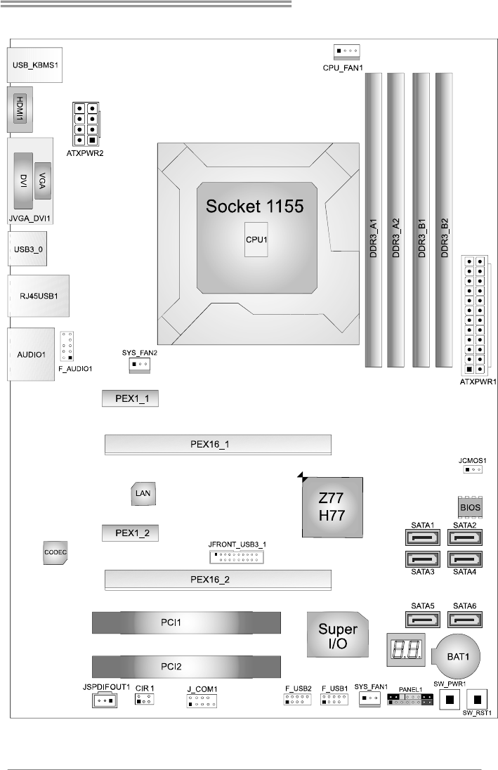
1.5 MOTHERBOARD LAYOUT
Note: ■ represents the 1st pin.
Motherboard Manual
6
CHAPTER 2: HARDWARE INSTALLATION
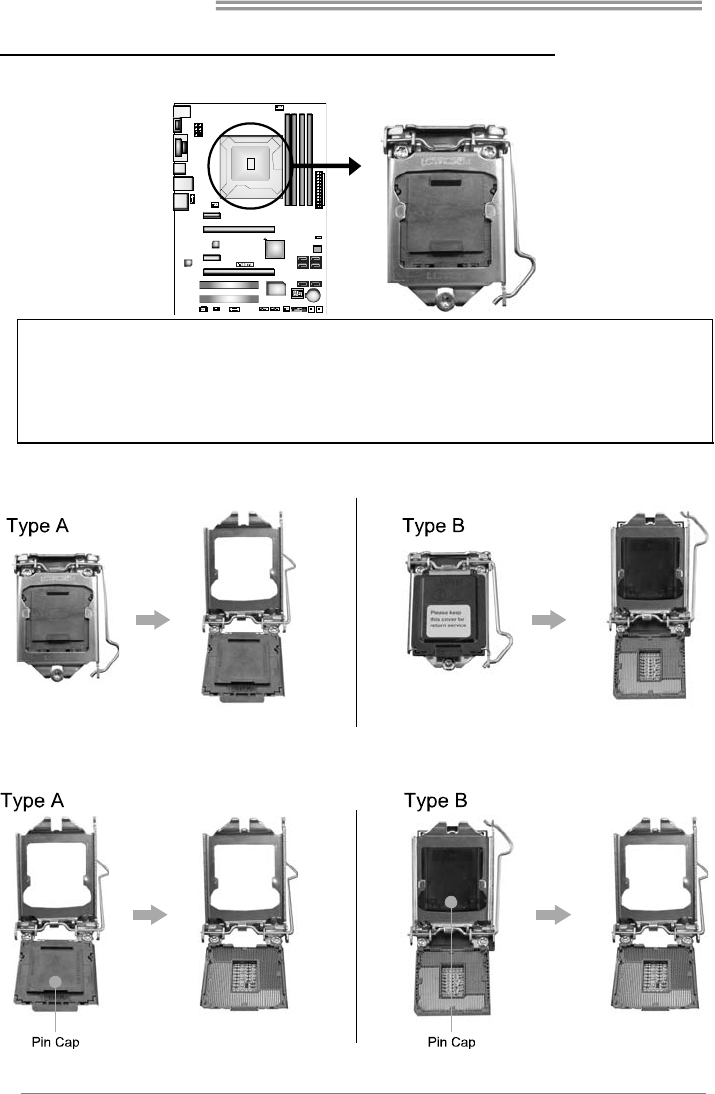
2.1 INSTALLING CENTRAL PROCESSING UNIT (CPU)
Notice:
1. Remove Pin Cap before installation, and make good preservation for future use. When the
CPU is removed, cover the Pin Cap on the empty socket to ensure pin legs won’t be
damaged.
2. The motherboard might equip with two different types of pin cap. Please refer below
instruction to remove the pin cap.
Step 1: Pull the socket locking lever out from the socket and then raise
the lever up.
Step 2: Remove the Pin Cap.
Hi-Fi Z77S/Hi-Fi H77S
7
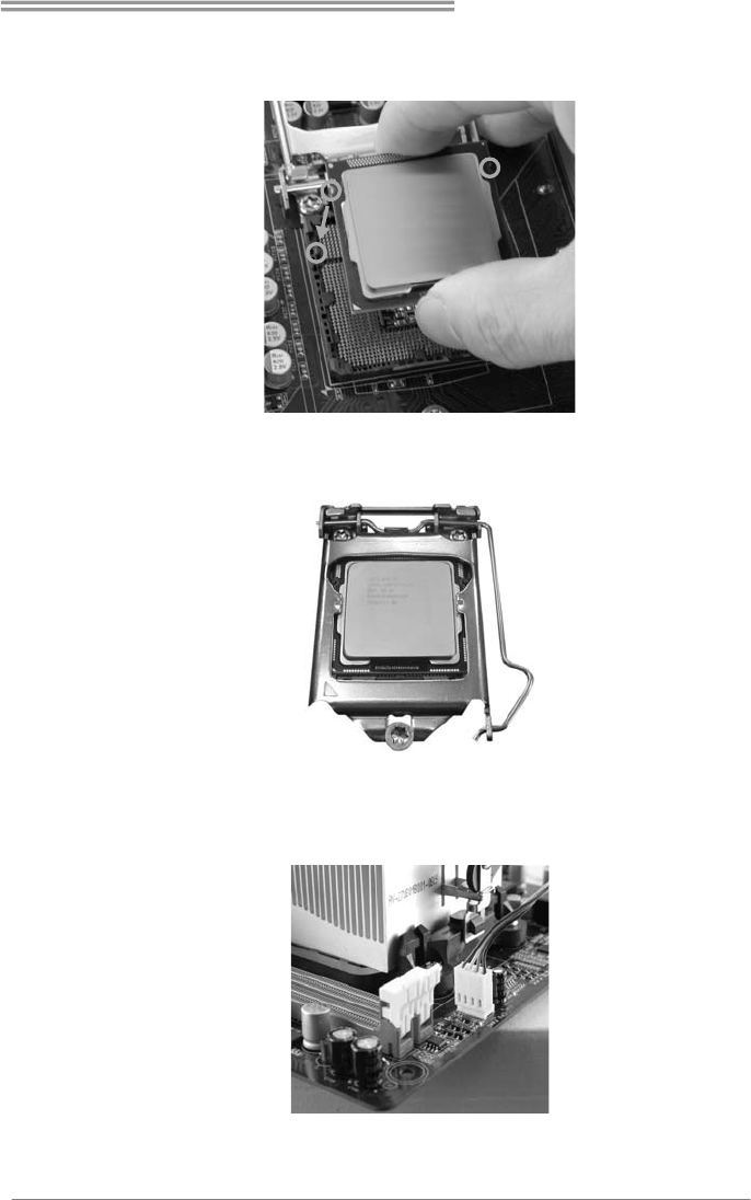
Step 3: Hold processor with your thumb and index fingers, oriented as
shown. Align the notches with the socket. Lower the processor
straight down without tilting or sliding the processor in the socket.
Step 4: Hold the CPU down firmly, and then lower the lever to locked
position to complete the installation.
Step 5: Put the CPU Fan and heatsink assembly on the CPU and buckle it
on the retention frame. Connect the CPU FAN power cable into
the CPU_FAN1 to complete the installation.
Motherboard Manual
8
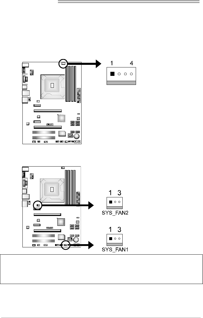
2.2 FAN HEADERS
These fan headers support cooling-fans built in the computer. The fan
cable and connector may be different according to the fan manufacturer.
Connect the fan cable to the connector while matching the black wire to
pin#1.
CPU_FAN1: CPU Fan Header
Pin Assignment
1 Ground
2 +12V
3 FAN RPM rate sense
4 Smart Fan Control
SYS_FAN1/SYS_FAN2: System Fan Headers
Pin
Assignment
1 Ground
2 +12V
3 FAN RPM rate sense
Note:
The SYS_FAN1/SYS_FAN2 support 3-pin head connectors; the CPU_FAN1 supports 4-pin head
connector. When connecting with wires onto connectors, please note that the red wire is the
positive and should be connected to pin#2, and the black wire is Ground and should be
connected to GND.
Hi-Fi Z77S/Hi-Fi H77S
9
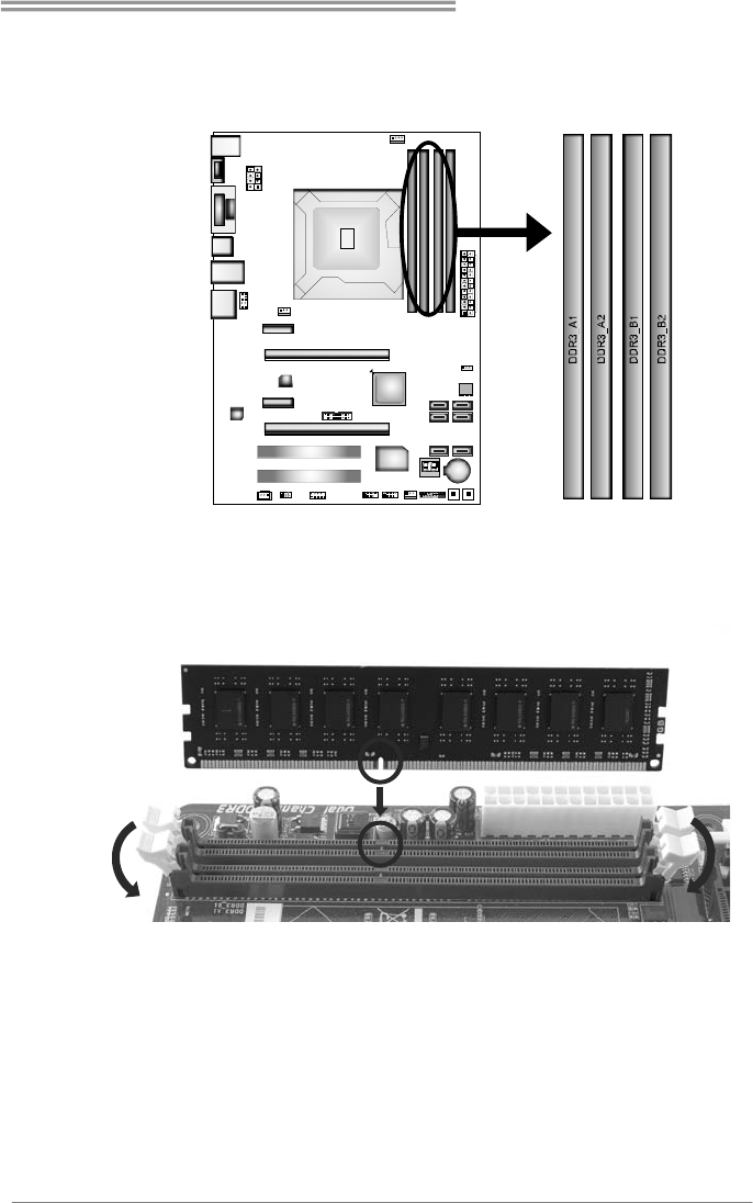
2.3 INSTALLING SYSTEM MEMORY
A. Memory Modules
1. Unlock a DIMM slot by pressing the retaining clips outward. Align a
DIMM on the slot such that the notch on the DIMM matches the
break on the Slot.
Motherboard Manual
10
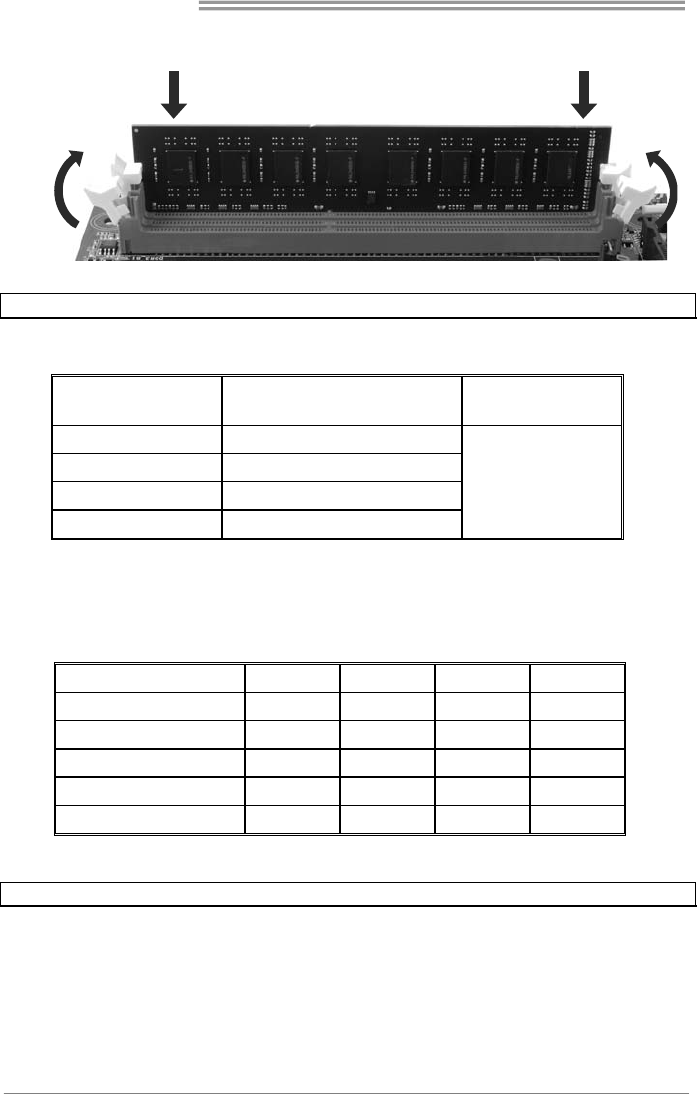
2. Insert the DIMM vertically and firmly into the slot until the retaining
chip snap back in place and the DIMM is properly seated.
Note: If the DIMM does not go in smoothly, do not force it. Pull it all the way out and try again.
B. Memory Capacity
DIMM Socket
Location DDR3 Module Total Memory
Size
DDR3_A1 512MB/1GB/2GB/4GB/8GB
DDR3_A2 512MB/1GB/2GB/4GB/8GB
DDR3_B1 512MB/1GB/2GB/4GB/8GB
DDR3_B2 512MB/1GB/2GB/4GB/8GB
Max is 32GB.
C. Dual Channel Memory Installation
Please refer to the following requirements to activate Dual Channel function:
Install memory module of the same density in pairs, shown in the table.
Dual Channel Status DDR3_A1 DDR3_A2 DDR3_B1 DDR3_B2
Enabled O X O X
Enabled X O X O
Enabled O O O O
Enabled O X X O
Enabled X O O X
(O means memory installed, X means memory not installed.)
Note: The DRAM bus width of the memory module must be the same (x8 or x16)
Hi-Fi Z77S/Hi-Fi H77S
11
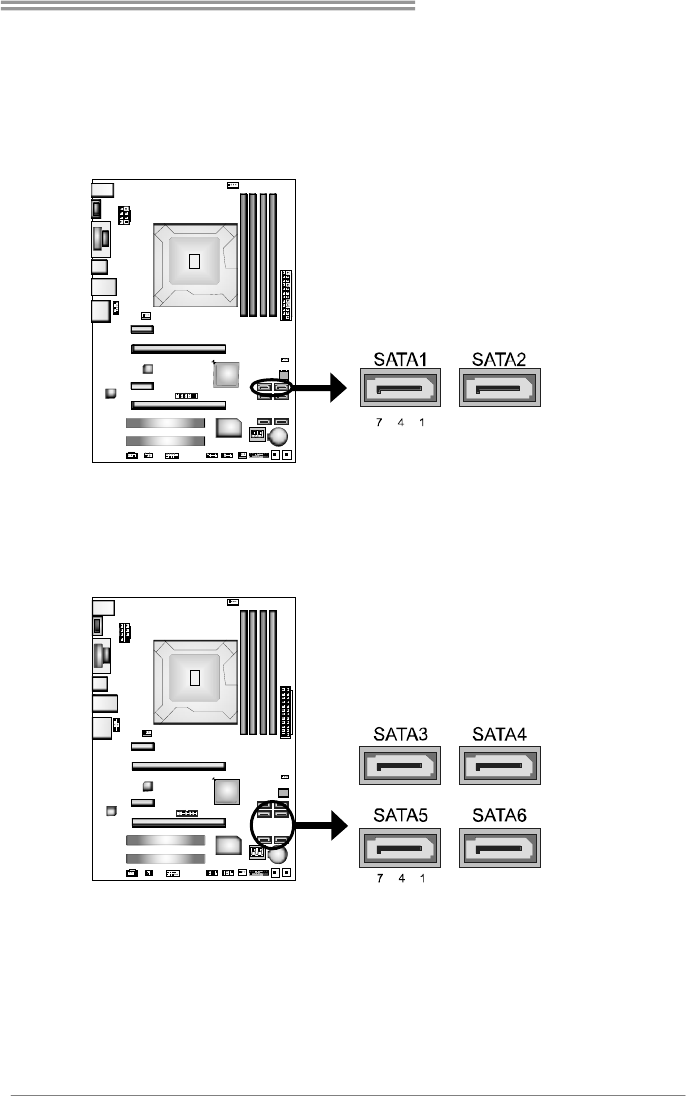
2.4 CONNECTORS AND SLOTS
SATA1/SATA2: Serial ATA3.0 Connectors
These connectors connect to SATA hard disk drives via SATA cables.
Those satisfy the SATA 3.0 spec and with transfer rate of 6.0Gb/s.
Pin
Assignment
1 Ground
2 TX+
3 TX-
4 Ground
5 RX-
6 RX+
7 Ground
SATA3 ~ 6: Serial ATA2.0 Connectors
These connectors connect to SATA hard disk drives via SATA cables.
Those satisfy the SATA 2.0 spec and with transfer rate of 3.0Gb/s.
Pin
Assignment
1 Ground
2 TX+
3 TX-
4 Ground
5 RX-
6 RX+
7 Ground
Motherboard Manual
12
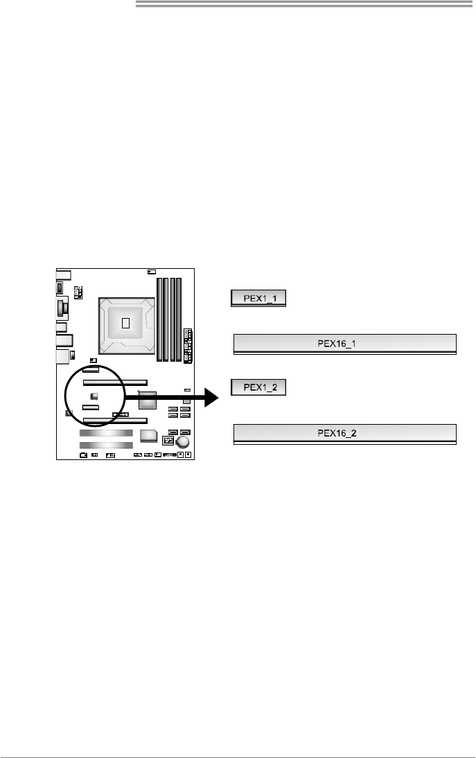
PEX16_1: PCI-Express Gen3 x16 (x16) Slot
- PCI-Express 3.0 compliant.
- Maximum theoretical realized bandwidth of 16GB/s simultaneously per
direction, for an aggregate of 32GB/s totally.
- PCI-E 3.0 is supported by Core i7-3xxx / i5-3xxx CPU.
PEX16_2: PCI-Express Gen2 x4 Slot
- PCI-Express 2.0 compliant.
- Maximum theoretical realized bandwidth of 2GB/s simultaneously per
direction, for an aggregate of 4GB/s totally.
PEX1_1/PEX1_2: PCI-Express Gen2 x1 Slot
- PCI-Express 2.0 compliant.
- Data transfer bandwidth up to 500MB/s per direction; 1GB/s in total.
Hi-Fi Z77S/Hi-Fi H77S
13
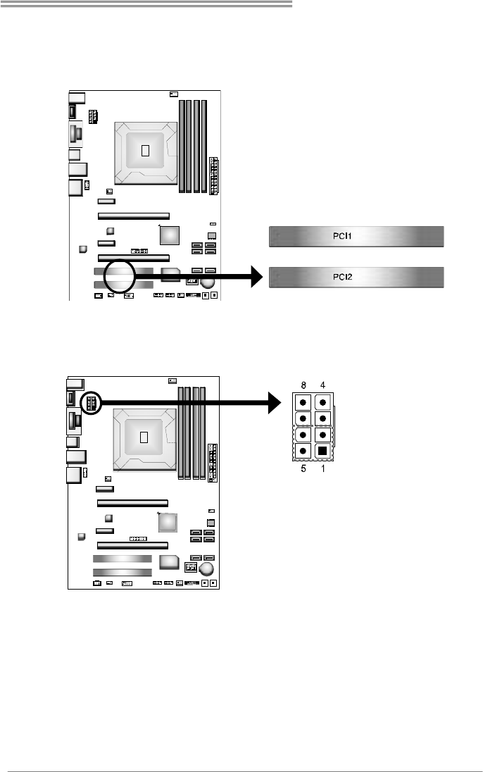
PCI1/PCI2: Peripheral Component Interconnect Slots
This motherboard is equipped with 2 standard PCI slots. PCI stands for
Peripheral Component Interconnect, and it is a bus standard for expansion
cards. This PCI slot is designated as 32 bits.
ATXPWR2: ATX Power Source Connectors
These connectors provide +12V to CPU power circuit. If the CPU power plug is
4-pin, please plug it into Pin 1-2-5-6 of ATXPWR2.
Pin
Assignment
1 +12V
2 +12V
3 +12V
4 +12V
5 Ground
6 Ground
7 Ground
8 Ground
Motherboard Manual
14
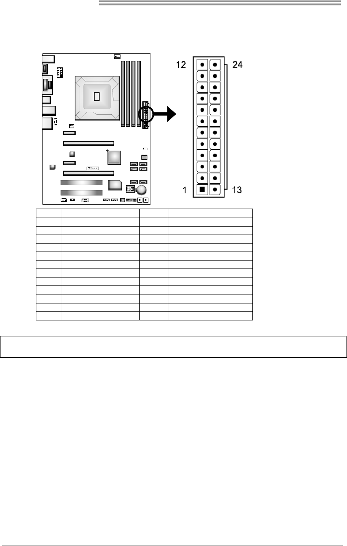
ATXPWR1: ATX Power Source Connector
This connector allows user to connect 24-pin power connector on the ATX
power supply.
Pin Assignment Pin Assignment
13 +3.3V 1 +3.3V
14 -12V 2 +3.3V
15 Ground 3 Ground
16 PS_ON 4 +5V
17 Ground 5 Ground
18 Ground 6 +5V
19 Ground 7 Ground
20 NC 8 PW_OK
21 +5V 9 Standby Voltage+5V
22 +5V 10 +12V
23 +5V 11 +12V
24 Ground 12 +3.3V
Note: Before you power on the system, please make sure that ATXPWR1 and ATXPWR2
connectors have been well plugged-in.
Hi-Fi Z77S/Hi-Fi H77S
15
CHAPTER 3: HEADERS & JUMPERS SETUP
3.1 HOW TO SETUP JUMPERS
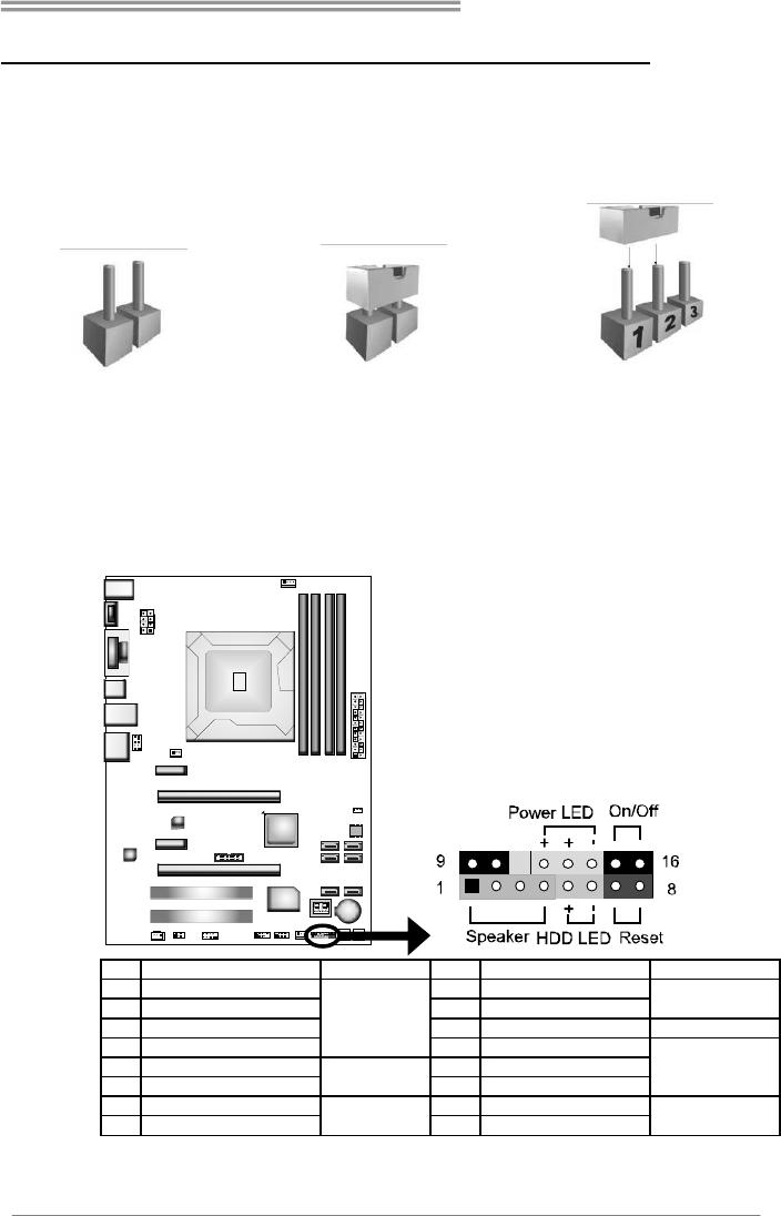
The illustration shows how to set up jumpers. When the jumper cap is
placed on pins, the jumper is “close”, if not, that means the jumper is
“open”.
Pin opened Pin closed Pin1-2 closed
3.2 DETAIL SETTINGS
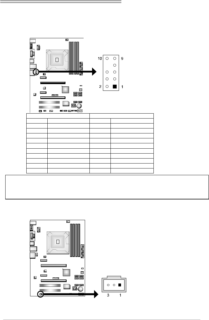
PANEL1: Front Panel Header
This 16-pin connector includes Power-on, Reset, HDD LED, Power LED, and
speaker connection. It allows user to connect the PC case’s front panel switch
functions.
Pin Assignment Function Pin Assignment Function
1 +5V 9 N/A
2N/A 10N/A
N/A
3 N/A 11 N/A N/A
4 Speaker
Speaker
Connector
12 Power LED (+)
5 HDD LED (+) 13 Power LED (+)
6 HDD LED (-)
Hard drive
LED 14 Power LED (-)
Power LED
7 Ground 15 Power button
8 Reset control Reset button 16 Ground Power-on button
Motherboard Manual
16
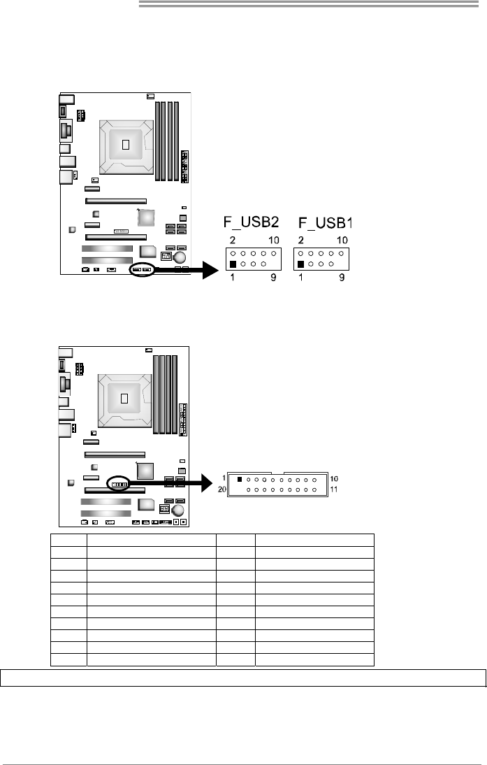
F_USB1/F_USB2: Headers for USB 2.0 Ports at Front Panel
These headers allow user to connect additional USB cable on the PC front panel,
and also can be connected with internal USB devices, like USB card reader.
Pin
Assignment
1 +5V (fused)
2 +5V (fused)
3 USB-
4 USB-
5 USB+
6 USB+
7 Ground
8 Ground
9 Key
10 NC
JFRONT_USB3_1: Header for USB 3.0 Ports at Front Panel
This header allows user to connect additional USB cable on the PC front panel,
and also can be connected with internal USB devices, like USB card reader.
Pin Assignment Pin Assignment
1 VBUS0 11 D2+
2 SSRX1- 12 D2-
3 SSRX1+ 13 Ground
4 Ground 14 SSTX2+
5 SSTX1- 15 SSTX2-
6 SSTX1+ 16 Ground
7 Ground 17 SSRX2+
8 D1- 18 SSRX2-
9 D1+ 19 VBUS1
10 ID 20 Key
Note: USB3.0 is only supported by Windows 7/8.
Hi-Fi Z77S/Hi-Fi H77S
17
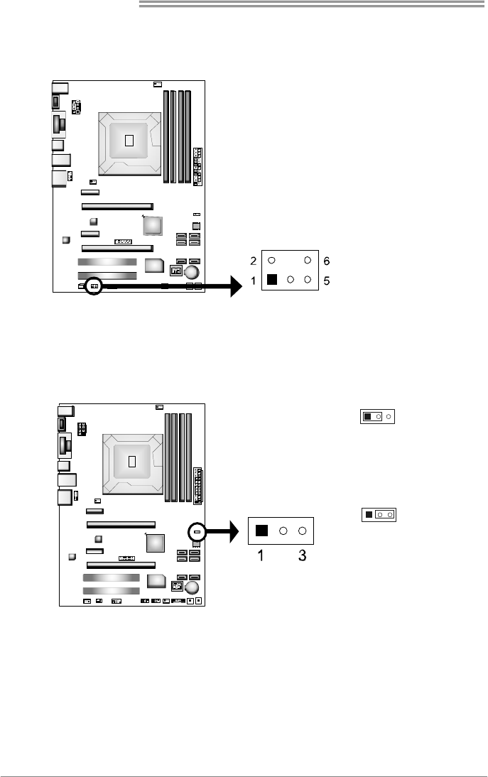
F_AUDIO1: Front Panel Audio Header
This header allows user to connect the front audio output cable with the PC front
panel. This header supports HD and AC’97 audio front panel connector.
HD Audio AC’97
Pin Assignment Pin Assignment
1 Mic Left in 1 Mic In
2 Ground 2 Ground
3 Mic Right in 3 Mic Power
4 GPIO 4 Audio Power
5 Right line in 5 RT Line Out
6 Jack Sense 6 RT Line Out
7 Front Sense 7 Reserved
8 Key 8 Key
9 Left line in 9 LFT Line Out
10 Jack Sense 10 LFT Line Out
Note1: It is recommended that you connect a high-definition front panel audio module to this
connector to avail of the motherboard's high definition audio capability.
Note2: Please try to disable the "Front Panel Jack Detection" if you want to use an AC'97 front
audio output cable. The function can be found via O.S. Audio Utility.
JSPDIFOUT1: Digital Audio-out Connector
This connector allows user to connect the PCI bracket SPDIF output header.
Pin
Assignment
1+5V
2 SPDIF_OUT
3 Ground
Motherboard Manual
18
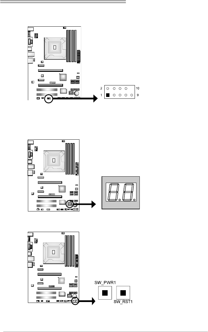
CIR1: Consumer IR Connector
This header is for infrared remote control and communication.
Pin Assignment
1 IrDA serial input
2 Ground
3 Ground
4 Key
5 IrDA serial output
6 IR Power
JCMOS1: Clear CMOS Header
Placing the jumper on pin2-3 allows user to restore the BIOS safe setting and
the CMOS data. Please carefully follow the procedures to avoid damaging the
motherboard.
13
Pin 1-2 Close:
Normal Operation (default).
13
Pin 2-3 Close:
Clear CMOS data.
※ Clear CMOS Procedures:
1. Remove AC power line.
2. Set the jumper to “Pin 2-3 close”.
3. Wait for five seconds.
4. Set the jumper to “Pin 1-2 close”.
5. Power on the AC.
6. Reset your desired password or clear the CMOS data.
Hi-Fi Z77S/Hi-Fi H77S
19
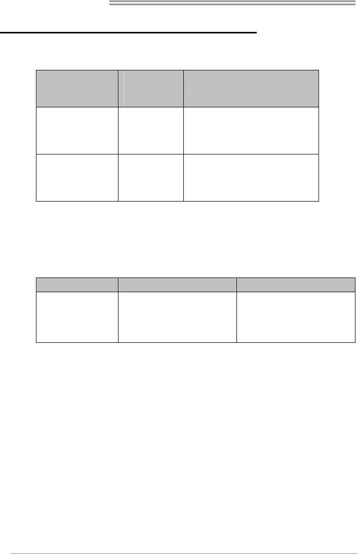
J_COM1: Serial Port Connector
The motherboard has a Serial Port Connector for connecting RS-232 Port.
Pin
Assignment
1 Carrier detect
2 Received data
3 Transmitted data
4 Data terminal ready
5 Signal ground
6 Data set ready
7 Request to send
8 Clear to send
9 Ring indicator
10 NC
BIOS POST Code/CPU Temperature Indicator
This indicator will show POST code while booting. After the booting sequence,
it will show current CPU temperature. Please refer to Chapter 6.3 for all the
BIOS POST codes.
On-Board Buttons
There are 2 on-board buttons.
SW_RST1: Reset button.
SW_PWR1: Power Switch button.
Motherboard Manual
20
CHAPTER 4: RAID / AHCI FUNCTIONS
4.1 OPERATING SYSTEM
CHIP
SATA
Controller
Configuration
Supporting OS
Intel Z77/H77
SATA1/SATA2/
SATA3/SATA4/
SATA5/SATA6
AHCI Windows XP SP2 (32 and 64 bit)
Windows Vista SP2 (32 and 64 bit)
Windows 7/8 (32 and 64 bit)
Intel Z77/H77
SATA1/SATA2/
SATA3/SATA4/
SATA5/SATA6
RAID Windows XP SP2 (32 and 64 bit)
Windows Vista SP2 (32 and 64 bit)
Windows 7/8 (32 and 64 bit)
The 'F6 Method'+ to enable RAID / AHCI Driver when installing Windows XP
1. Before you start Windows installation, copy the proper files for the Windows
version on USB floppy.
Windows XP 32 Windows XP 64
SATA1/SATA2/
SATA3/SATA4/
SATA5/SATA6
AHCI/RAID Driver
Path
x:\Driver\Chipset\Intel\SATA\
7\F6flpy32\Driver\
x:\Driver\Chipset\Intel\SATA\
7\F6flpy64\Driver\
2. When the operating system installation starts, follow Windows indication by
pressing F6 to load the driver.
Hi-Fi Z77S/Hi-Fi H77S
21
Enable RAID / AHCI Driver when installing Windows 8/7/Vista
1. Before you start Windows installation, copy the proper files for the Windows
version to any USB storage.
Windows 7/
Vista 32
Windows 7/
Vista 64
Windows 8 32 Windows 8 64
SATA1/SATA2/
SATA3/SATA4/
SATA5/SATA6
AHCI/RAID
Driver Path
x:\Driver\Chipse
t\Intel\SATA\7\
F6flpy32\Driver\
x:\Driver\Chipse
t\Intel\SATA\7\
F6flpy64\Driver\
x:\Driver\Chipse
t\Intel\SATA\
Win8\F6flpy32\
Driver\
x:\Driver\Chipse
t\Intel\SATA\
Win8\F6flpy64\
Driver\
2. Follow Windows 7 / Vista indication to load the driver in the installation process.
4.2 RAID ARRAYS
CONNECTOR BY CHIP SPEED Support
SATA1/SATA2 Intel Z77/H77 6 Gb/s. RAID 0 / 1 / 5 / 10
SATA3/SATA4/SATA5/SATA6 Intel Z77/H77 3 Gb/s. RAID 0 / 1 / 5 / 10
RAID supports the following types of RAID arrays:
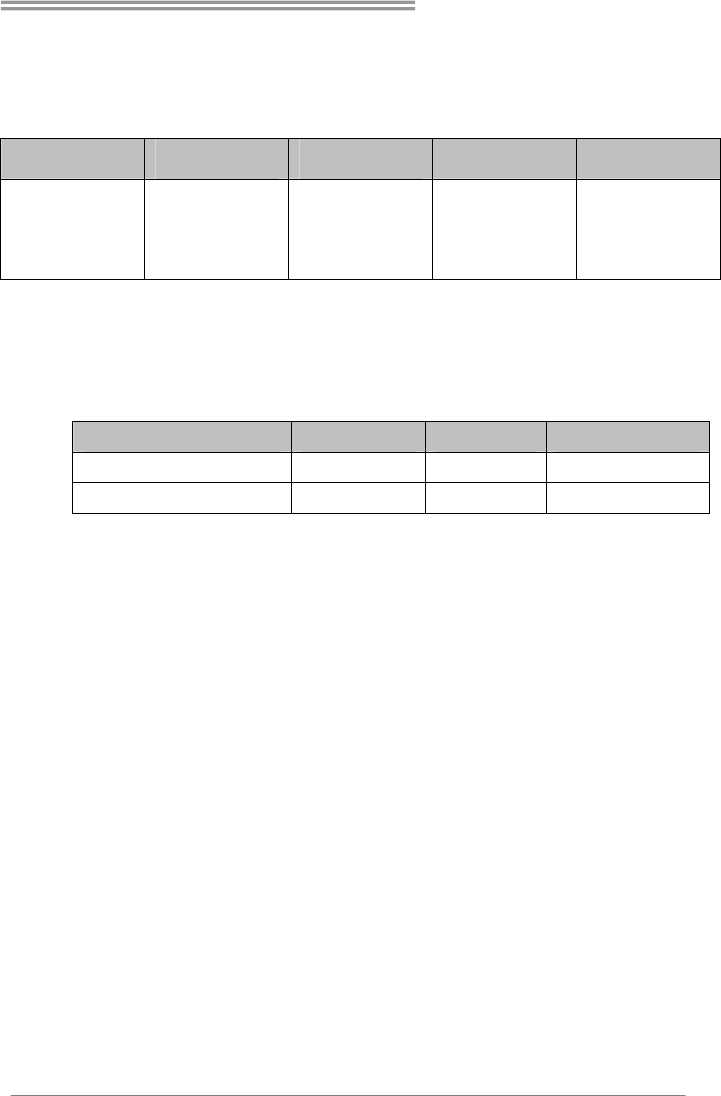
RAID 0: RAID 0 defines a disk striping scheme that improves disk read and write
times for many applications.
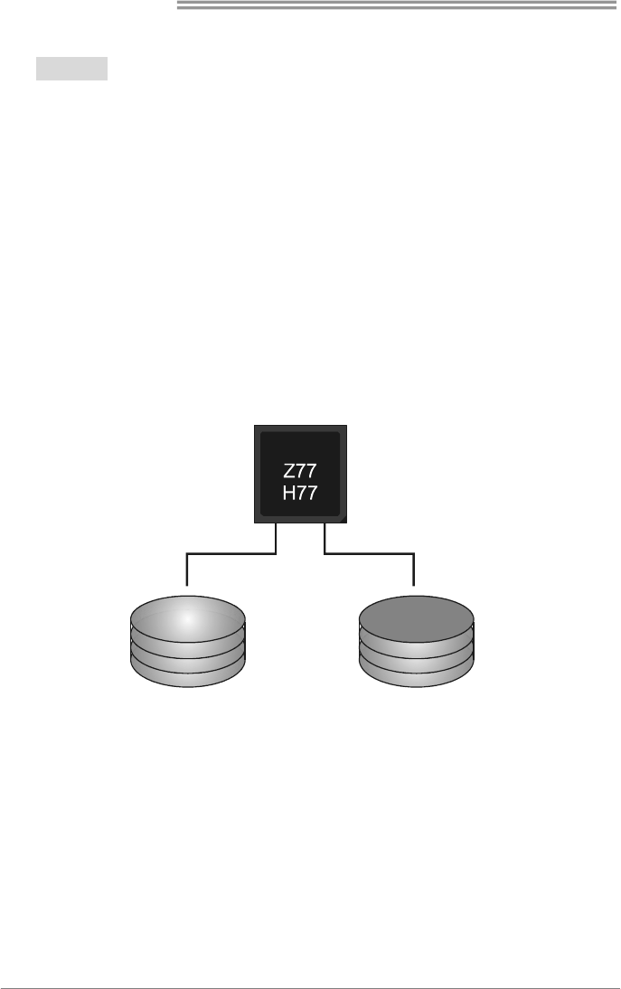
RAID 1: RAID 1 defines techniques for mirroring data.
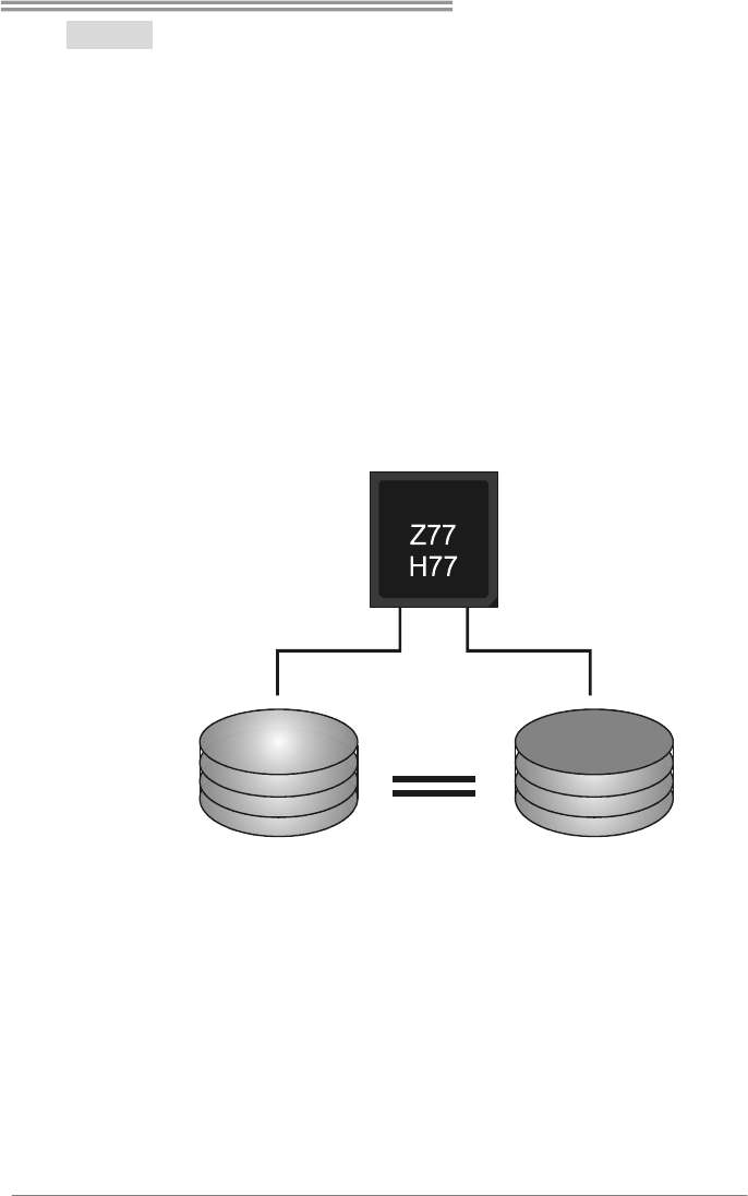
RAID 10: RAID 10 combines the techniques used in RAID 0 and RAID 1.
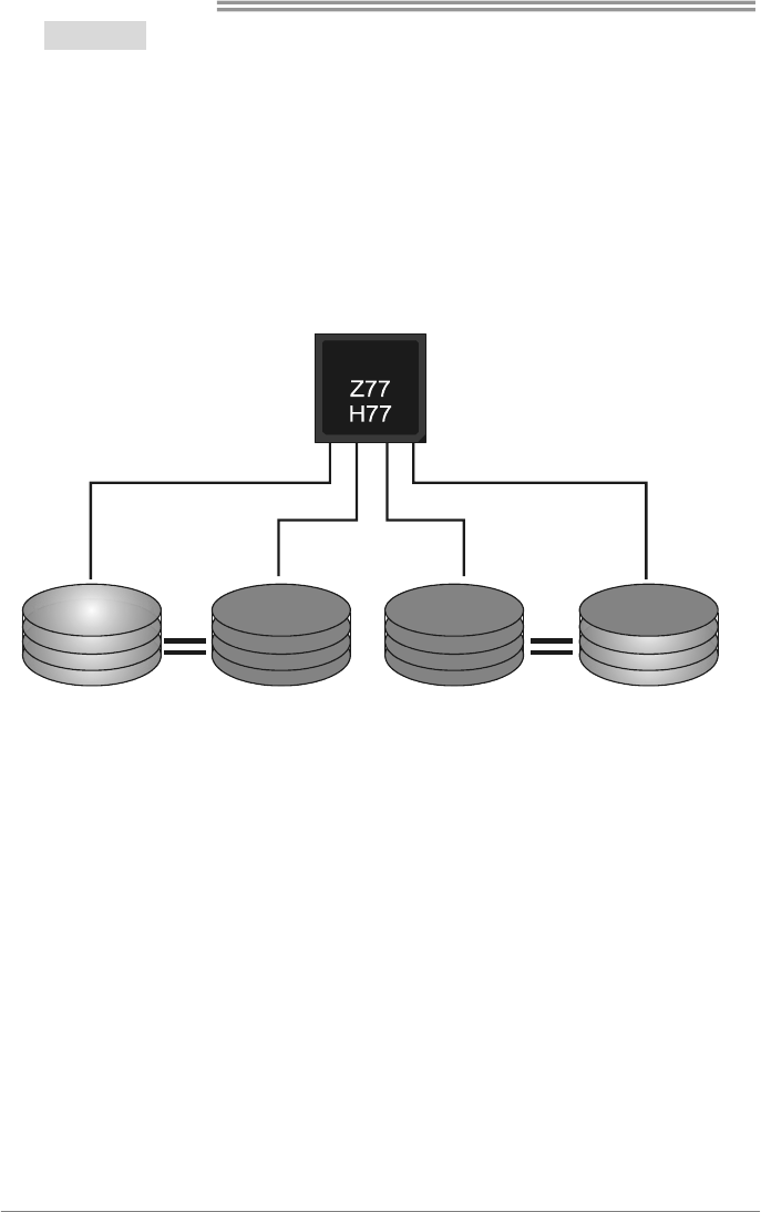
RAID 5: RAID 5 provides fault tolerance and better utilization of disk capacity.
Motherboard Manual
22
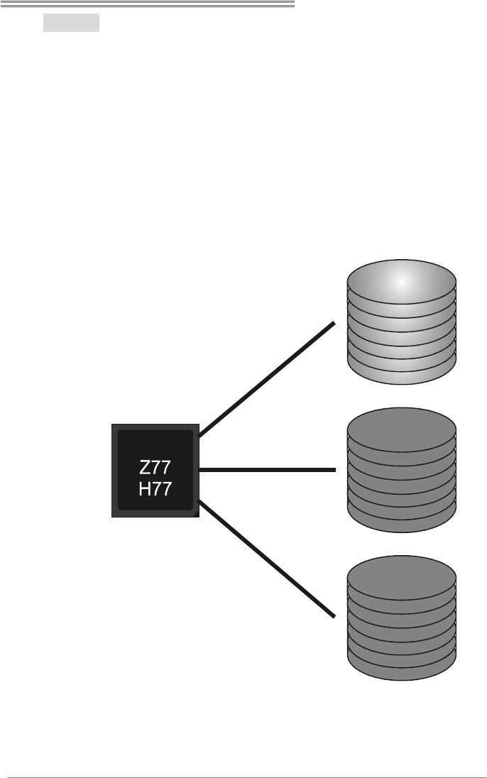
4.3 HOW RAID WORKS
RAID 0:
The controller “stripes” data across multiple drives in a RAID 0 array system. It breaks
up a large file into smaller blocks and performs disk reads and writes across multiple
drives in parallel. The size of each block is determined by the stripe size parameter,
which you set during the creation of the RAID set based on the system environment. This
technique reduces overall disk access time and offers high bandwidth.
Features and Benefits
Drives: Minimum 2, and maximum is up to 6 or 8. Depending on the
platform.
Uses: Intended for non-critical data requiring high data throughput, or any
environment that does not require fault tolerance.
Benefits: provides increased data throughput, especially for large files. No
capacity loss penalty for parity.
Drawbacks: Does not deliver any fault tolerance. If any drive in the array
fails, all data is lost.
Fault Tolerance: No.
Total Capacity: (Minimal. HDD Capacity) x (Connected HDDs Amount)
Block 1
Block 3
Block 5
Block 2
Block 4
Block 6
Hi-Fi Z77S/Hi-Fi H77S
23
RAID 1:
Every read and write is actually carried out in parallel across 2 disk drives in a RAID 1
array system. The mirrored (backup) copy of the data can reside on the same disk or on a
second redundant drive in the array. RAID 1 provides a hot-standby copy of data if the
active volume or drive is corrupted or becomes unavailable because of a hardware failure.
RAID techniques can be applied for high-availability solutions, or as a form of automatic
backup that eliminates tedious manual backups to more expensive and less reliable
media.
Features and Benefits
Drives: Minimum 2, and maximum is 2.
Uses: RAID 1 is ideal for small databases or any other application that
requires fault tolerance and minimal capacity.
Benefits: Provides 100% data redundancy. Should one drive fail, the
controller switches to the other drive.
Drawbacks: Requires 2 drives for the storage space of one drive.
Performance is impaired during drive rebuilds.
Fault Tolerance: Yes.
Block 1
Block 2
Block 3
Block 1
Block 2
Block 3
Motherboard Manual
24
RAID 10:
RAID 1 drives can be stripped using RAID 0 techniques. Resulting in a RAID 10
solution for improved resiliency, performance and rebuild performance.
Features and Benefits
Drives: Minimum 4, and maximum is 6 or 8, depending on the platform.
Benefits: Optimizes for both fault tolerance and performance, allowing for
automatic redundancy. May be simultaneously used with other RAID levels
in an array, and allows for spare disks.
Drawbacks: Requires twice the available disk space for data redundancy,
the same as RAID level 1.
Fault Tolerance: Yes.
Block 1
Block 3
Block 5
Block 2
Block 4
Block 6
Block 1
Block 3
Block 5
Block 2
Block 4
Block 6
Hi-Fi Z77S/Hi-Fi H77S
25
RAID 5:
RAID 5 stripes both data and parity information across three or more drives. It writes
data and parity blocks across all the drives in the array. Fault tolerance is maintained by
ensuring that the parity information for any given block of data is placed on a different
drive from those used to store the data itself.
Features and Benefits
Drives: Minimum 3.
Uses: RAID 5 is recommended for transaction processing and general
purpose service.
Benefits: An ideal combination of good performance, good fault tolerance,
and high capacity and storage efficiency.
Drawbacks: Individual block data transfer rate same as a single disk. Write
performance can be CPU intensive.
Fault Tolerance: Yes.
Disk 1
DATA 3
PARITY
DATA 7
DATA 1
DATA 9
PARITY
Disk 2
PARITY
DATA 5
DATA 8
DATA 2
PARITY
DATA 11
Disk 3
DATA 4
DATA 6
PARITY
PARITY
DATA 10
DATA 12

Motherboard Manual
26
4.4 INTEL SMART RESPONSE TECHNOLOGY
With Intel(R) Smart Response Technology, the performance of RAID with an Intel
SSD drive can be improved better.
Installing Smart Response Technology
1. Install RAID drives (RAID 0, 1, 5) and an Intel SSD.
2. Activate RAID mode from BIOS, and install operating system.
3. Insert the Setup DVD to the optical drive, and Install all drivers (including
Intel(R) Smart Response Technology Driver). After all processes finish,
reboot the system.
4. Intel(R) SRT service icon will show in notification area. Double click it to
open the main windows.
5. Select “Accelerate” page, and make sure the status of accelerated device
has been enabled accelerated.
Hi-Fi Z77S/Hi-Fi H77S
27
CHAPTER 5: UEFI BIOS & SOFTWARE
5.1 UEFI
BIOS
UEFI BIOS Features
Overclocking Navigator Engine (O.N.E.)
Self Recovery System (S.R.S)
Smart Fan Function
BIO-Flasher: Update UEFI BIOS file from USB Flash Drive
!! WARNING!!
For better system performance, the UEFI BIOS firmware is being continuously updated. The UEFI
BIOS information described below in this manual is for your reference only and the actual UEFI
BIOS information and settings on board may be different from this manual. For further
information of setting up the UEFI BIOS, please refer to the UEFI BIOS Manual in the Setup DVD.
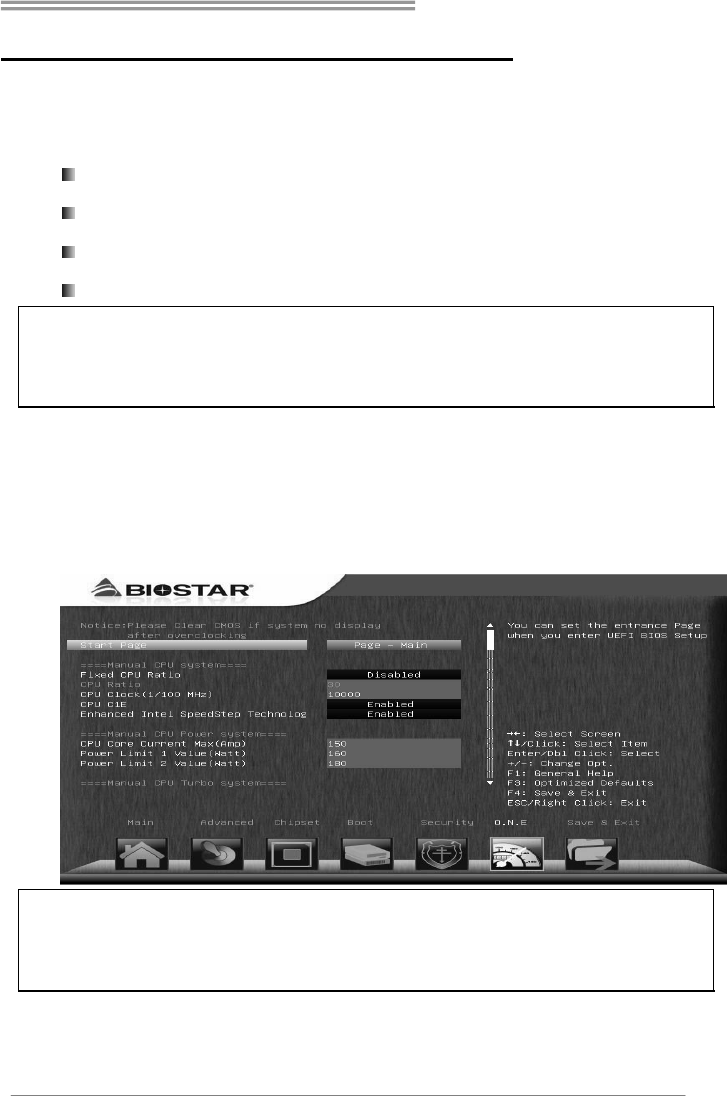
A. Overclocking Navigator Engine (O.N.E.)
O.N.E provides 4 systems allowing users to customize personal overclock
settings: Manual CPU System, Manual Memory System, Manual PWM
System, and Manual Voltage System.
Note1: Not all types of CPU perform above overclock setting ideally; the difference will be based
on the selected CPU model.
Note2: Overclock is an optional process, but not a “must-do” process; it is not recommended for
inexperienced users. Therefore, we will not be responsible for any hardware damage which may
be caused by overclocking. We also would not guarantee any overclocking performance.
Motherboard Manual
28
B. Self Recovery System (S.R.S.)
This function can’t be seen under UEFI BIOS setup, and is always on whenever
the system starts up.
However, it can prevent system hang-up due to inappropriate overclock
actions.
When the system hangs up, S.R.S. will automatically log in the default UEFI
BIOS setting, and all overclock settings will be re-configured.
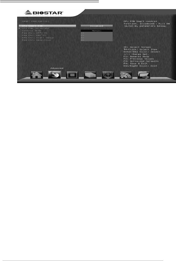
C. Smart Fan Function
Smart Fan Function is under “Smart Fan Control” in “Advanced Menu”.
This is a brilliant feature to control CPU/System Temperature vs. Fan speed.
When enabling Smart Fan function, Fan speed is controlled automatically by
CPU/System temperature.
This function will protect CPU/System from overheat problem and maintain the
system temperature at a safe level.
↓
Hi-Fi Z77S/Hi-Fi H77S
29
CPU Smart FAN
This item allows you to control the CPU Smart Fan function.
CPU FAN Calibrate
Press [ENTER] to calibrate CPU FAN.
Control Mode
This item provides several operation modes of the fan.
Fan Ctrl OFF(℃)
When CPU temperature is lower than this value, the CPU fan will keep
lowest RPM. The range is from 0~50, with an interval of 1.
Fan Ctrl On(℃)
When CPU temperature is higher than this value, the CPU fan controller
will turn on. The range is from 0~70, with an interval of 1.
Fan Ctrl Start Value
This item sets CPU FAN Start Speed Value. The range is from 0~255, with
an interval of 1.
Fan Ctrl Sensitive
The bigger the numeral is, the higher the FAN speed is. The range is from
1~255, with an interval of 1.
Motherboard Manual
30
5.2 SOFTWARE
Installing Software
1. Insert the Setup DVD to the optical drive. The driver installation program
would appear if the Auto-run function has been enabled.
2. Select Software Installation, and then click on the respective software
title.
3. Follow the on-screen instructions to complete the installation.
Launching Software
After the installation process is completed, you will see the software icon
showing on the desktop. Double-click the icon to launch it.
Due to the H77 chipset limitation, the most overclocking functions will
not be available for Hi-Fi H77S motherboard.
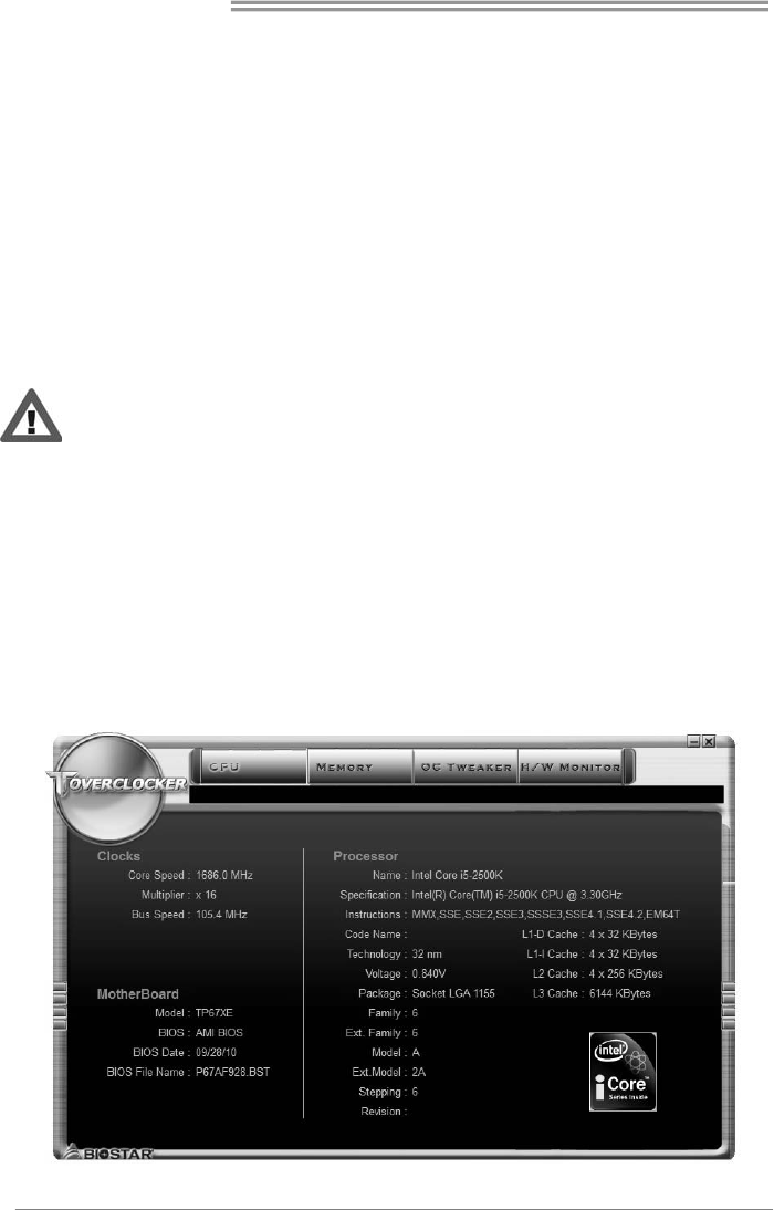
TOverclocker
TOverclocker presents a simple Windows-based system performance
enhancement and manageability utility. It features several powerful and easy
to use tools such as Overclocking for enhancing system performance, also for
special enhancement on CPU and Memory. Smart-Fan management and PC
health are for monitoring system status. This utility also allows you to make
overclocking profiles saving unlimitedly, and pre-set OC modes are for easy
OC. (The illustration below is for reference only)
Hi-Fi Z77S/Hi-Fi H77S
31
The CPU tab provides information on the CPU and motherboard.
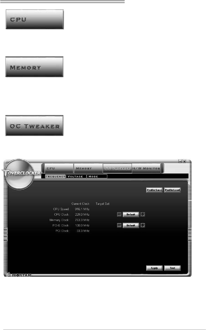
The Memory tab provides information on the memory module(s).
You can select memory module on a specific slot to see its information.
The OC Tweaker tab allows you to change system clock settings and voltages
settings. It also provides six pre-set modes for you:
Motherboard Manual
32
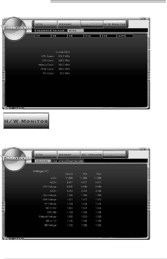
3 Pre-set Modes: V6, V12, AUTO for different overclocking experience.
The HW Monitor tab allows you to monitor hardware voltage, fan speed, and
temperature. Besides, you also can set related values for CPU Smart Fan.
Hi-Fi Z77S/Hi-Fi H77S
33
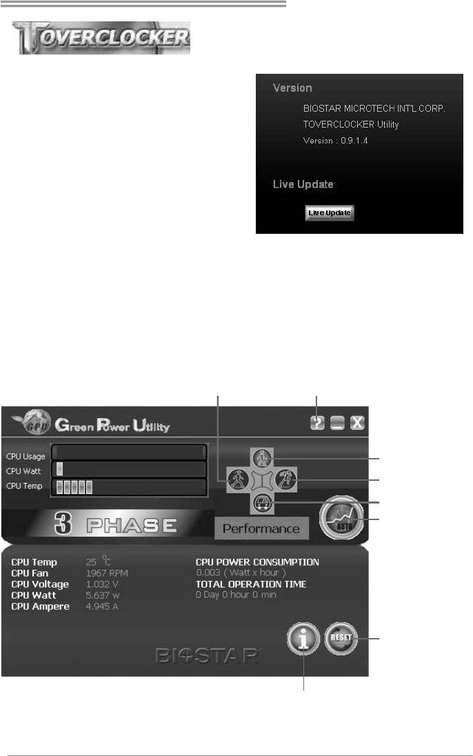
Pressing TOVERCLOCKER logo
displays information about
manufacturer and software version.
You can update current version by
clicking the button “Live Update.”
Green Power II Utility
BIOSTAR G.P.U II (Green Power Utility) is a new function. The utility enhances
energy efficiency by disabling extra phases while CPU is on light loading; it
features 4+1 power phases, current power saving, and toal power saving. This
tool integrates a friendly GUI to monitor your CPU Usage, CPU Watt, and CPU
Temperature. Moreover, it optimizes power saving and best power efficiency
on your system. (The illustration below is for reference only)
Display manufacturer &
software version information
Display CPU
information
Reset Time &
Consumption
Auto Phase Mode
Maxi-Energy Mode
Typical Mode
Medium Mode
Performance
Mode

Motherboard Manual
34
G.P.U Mode Setting
This utility provides five modes, upon your requirements, to improve
system performance or to save power consumption.
Note: Even if the modes saving more power consumption are chosen, the system still can keep
excellent performance.
Auto Phase Mode
System switches the mode automatically according to current system
loading condition.
Performance Mode
This is the mode saving power consumption most. Least energy will
be used in the system.
Typical Mode
Compared with that in Performance Mode, energy consumption in this
mode is a little bit more.
Medium Mode
This is the standard system power saving mode.
Maxi-Energy Mode
This is the best system performance mode.
Hi-Fi Z77S/Hi-Fi H77S
35
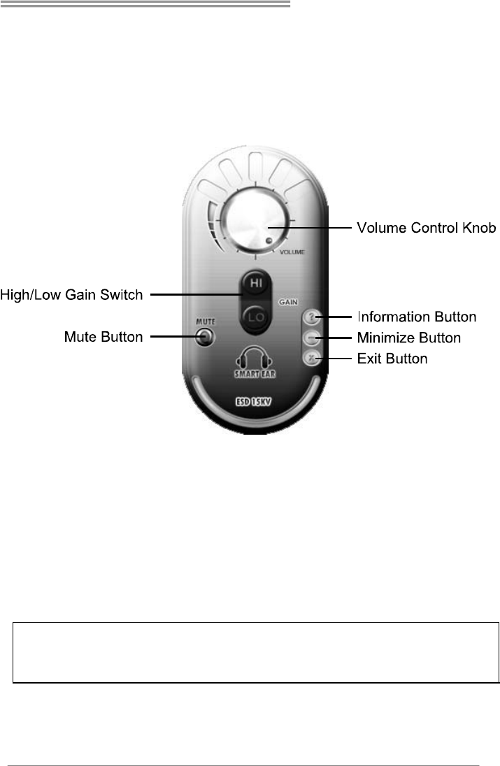
Smart EAR
Smart EAR is a windows-based audio utility which allows you to easily
adjust system volume. With its user-friendly GUI, you can also adjust
impedance setting (Low/High Gain) to optimize your headphone
performance.
z High/Low Gain Switch: Keep the gain switch to low for low impedance
headphone and set to high for high impedance headphone.
z Mute Button: To disable system sound
z Volume Control Knob: The volume can be finely adjusted by turning the
knob either clockwise or anti-clockwise to increase or decrease system
volume accordingly.
z Information Button: Get information of the application
z Minimize Button: Minimize the application window to the taskbar
z Exit Button: Exit the application
Note:
1. Smart EAR is only supported by Windows 7/8 and BIOSTAR Hi-Fi series motherboards.
2. High/Low Gain Switch is only for “Front Panel Audio Header”, please make sure you are
connecting your headphone to the front panel I/O.
Motherboard Manual
36
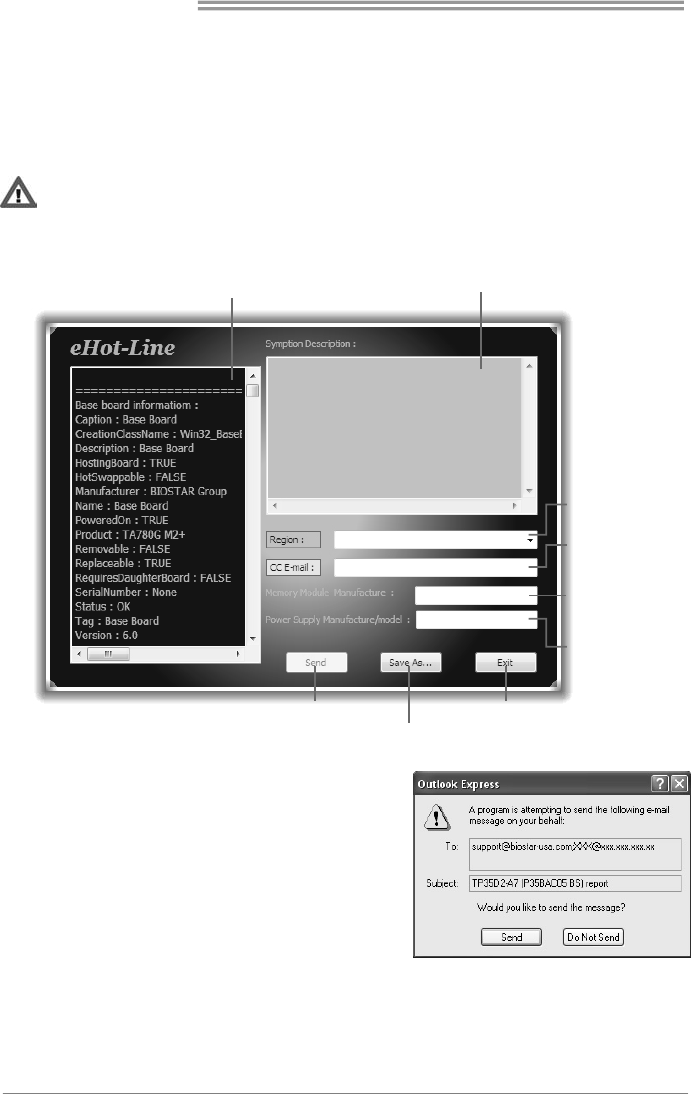
eHot-Line (Optional)
eHot-Line is a convenient utility that helps you to contact with our
Tech-Support system. This utility will collect the system information which is
useful for analyzing the problem you may have encountered, and then send
these information to our tech-support department to help you fix the problem.
Before you use this utility, please set Outlook Express as your default e-mail client application program.
This block will show
the information which
would be collect ed in
the mail.
Provide the e-mail
address that you would
like to send the copy to.
Provide the name of
the power supply
manufacturer and the
model no.
Send the mail out.
Save these information to a .txt file
Exit this dialog.
Select your area or
the area close to you.
*
Provide the name of
the memory module
manufacturer.
*
Describe condition
of your system.
*
*
represents important
in formation that you
must provide. Without
this information, you may
not be able to send out
the mail.
After filling up this information, click “Send”
to send the mail out. A warning dialog would
appear asking for your confirmation; click
“Send” to confirm or “Do Not Send” to cancel.
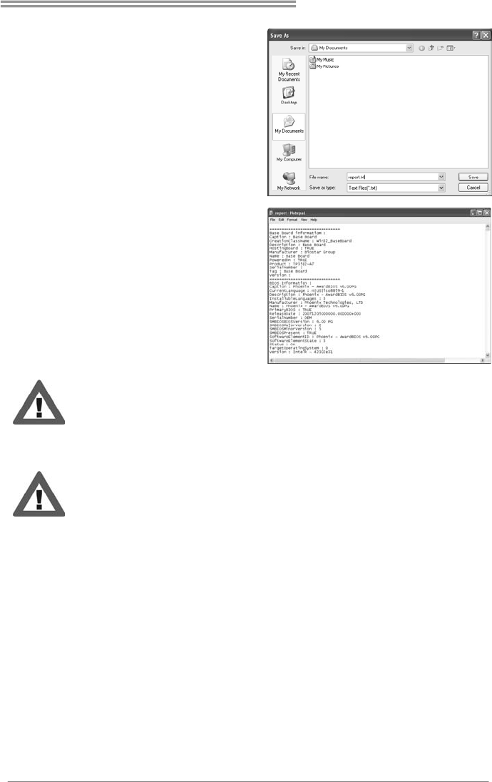
If you want to save this information to a .txt file, click “Save As…” and then you
will see a saving dialog appears asking you to enter file name.
Hi-Fi Z77S/Hi-Fi H77S
37
Enter the file name and then click
“Save”. Your system information
will be saved to a .txt file.
Open the saved .txt file, you will
see your system information
including
motherboard/BIOS/CPU/video/
device/OS information. This
information is also concluded in
the sent mail.
We will not share customer’s data with any other third parties,
so please feel free to provide your system information while using
eHot-Line service.
If you are not using Outlook Express as your default e-mail client
application, you may need to save the system information to a .txt file
and send the file to our tech support with other e-mail application.
Motherboard Manual
38
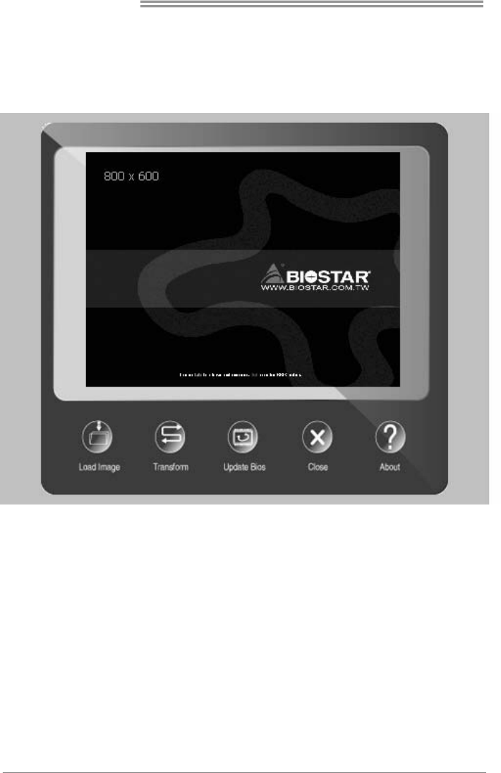
BIOScreen Utility (Optional)
This utility allows you to personalize your boot logo easily. You can choose
JPG or BMP as your boot logo so as to customize your computer.
Please follow the following instructions to update boot logo:
1. Load Image:Choose the picture as the boot logo.
2. Transform:Transform the picture for BIOS and preview the result.
3. Update Bios:Write the picture to BIOS Memory to complete the update.
Hi-Fi Z77S/Hi-Fi H77S
39
5.3 BIOS UPDATE
There are three ways to update the BIOS:
BIOS Update Utility, BIOS Online Update Utility and BIOS Flasher.
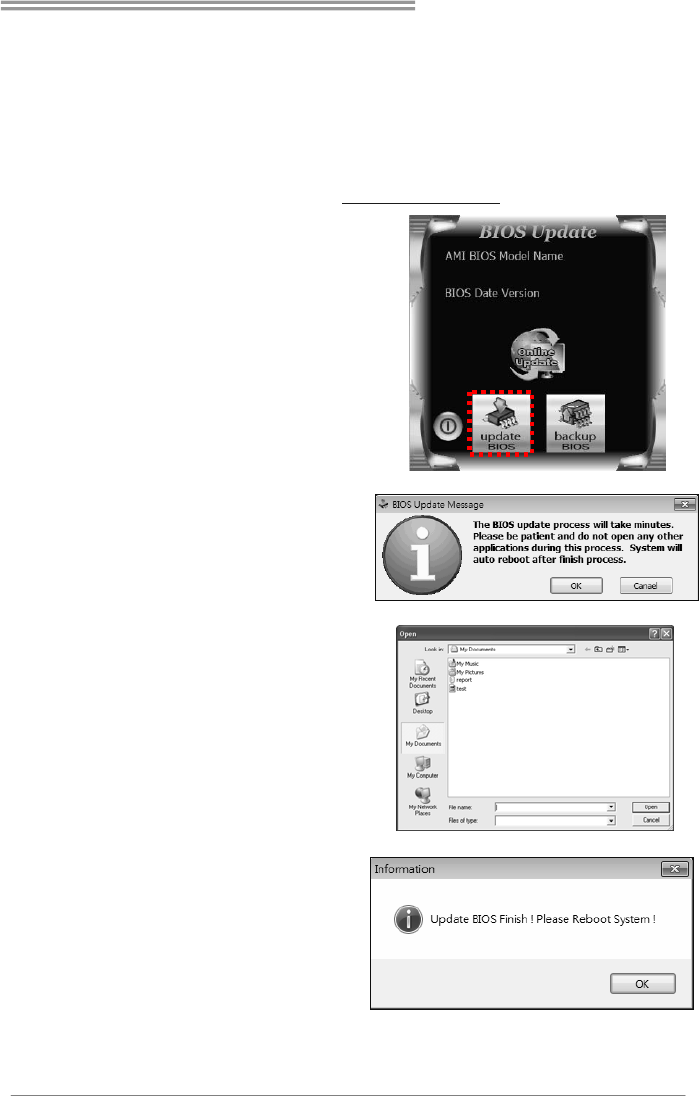
1. BIOS Update Utility
1. Installing BIOS Update Utility from the DVD Driver.
2. Download the proper BIOS from www.biostar.com.tw .
3. Open BIOS Update Utility and
click the Update BIOS button on the
main screen.
4. A warning message will show up
to request your agreement to start
the BIOS update. Click Yes to start
the update procedure.
5. Choose the location for your
BIOS file in the system. Please
select the proper BIOS file, and then
click on Open. It will take several
minutes, please be patient.
6. After the BIOS Update process is
finished, click on OK to reboot the
system.
Motherboard Manual
40
7. While the system boots up and the full screen logo shows up, please press
the <Delete> key to enter BIOS setup.
After entering the BIOS setup, please go to the Save & Exit, using the Restore
Defaults function to load Optimized Defaults, and select Save Changes and
Reset to restart the computer. Then, the BIOS Update is completed.
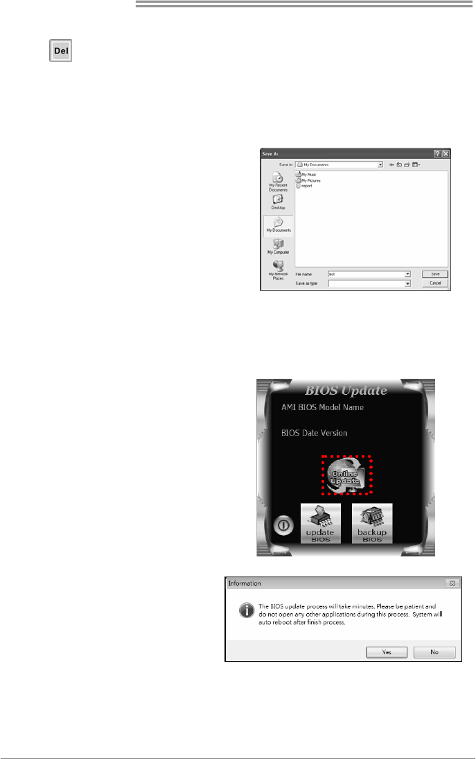
Backup BIOS
Click the Backup BIOS button on
the main screen for the backup of
BIOS, and select a proper location
for your backup BIOS file in the
system, and click Save.
2. Online Update Utility
1. Installing BIOS Update Utility from the DVD Driver.
2. Please make sure the system is connected to the internet before using this
function.
3. Open BIOS Update Utility and
click the Online Update button
on the main screen.
4. An open dialog will show up to
request your agreement to
start the BIOS update. Click
Yes to start the online update
procedure.
Hi-Fi Z77S/Hi-Fi H77S
41
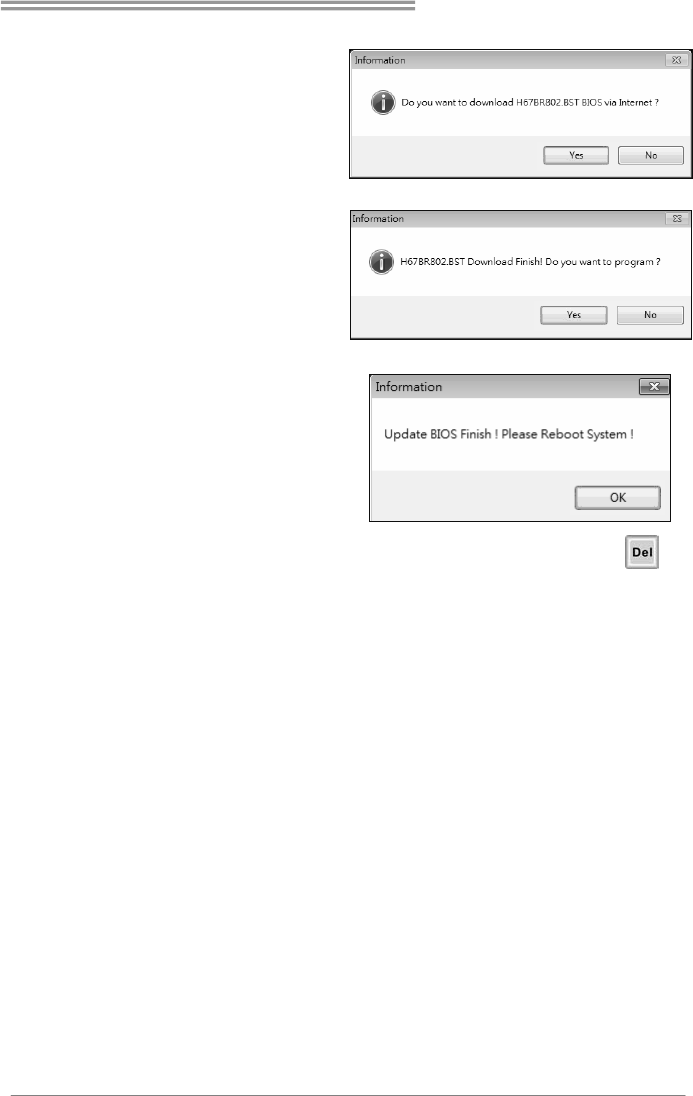
5. If there is a new BIOS version,
the utility will ask you to
download it. Click Yes to
proceed.
6. After the download is
completed, you will be asked
to program (update) the BIOS
or not. Click Yes to proceed.
7. After the updating process is
finished, you will be asked you
to reboot the system. Click
OK to reboot.
8. While the system boots up and the full screen logo shows up, press
<Delete> key to enter BIOS setup.
After entering the BIOS setup, please go to the Save & Exit, using the Restore
Defaults function to load Optimized Defaults, and select Save Changes and
Reset to restart the computer. Then, the BIOS Update is completed.
Motherboard Manual
42
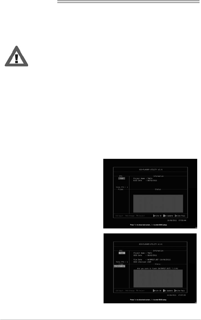
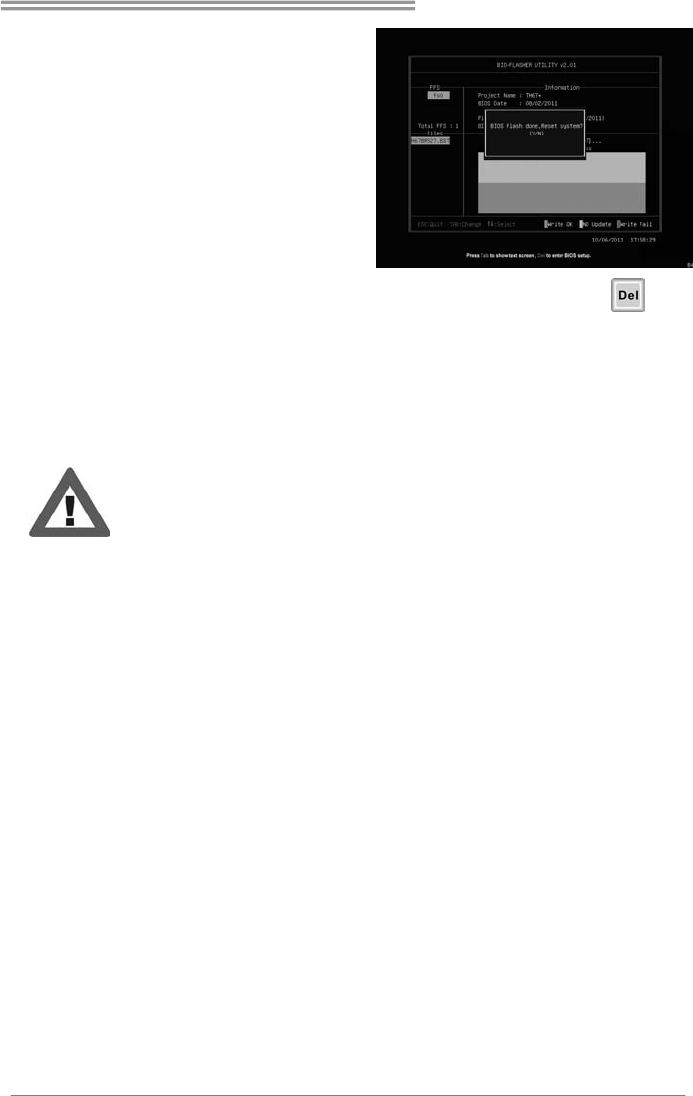
3. BIOSTAR BIOS Flasher
BIOSTAR BIOS Flasher is a BIOS flashing utility providing you an easy and simple
way to update your BIOS via USB pen drive.
This utility only allows storage device with FAT32/16 format and single
partition.
Shutting down or resetting the system while updating the BIOS will lead
to system boot failure.
The BIOSTAR BIOS Flasher is built in the BIOS ROM. To enter the utility, press
<F12> during the Power-On Self Tests (POST) procedure while booting up.
Updating BIOS with BIOSTAR BIOS Flasher
1. Go to the website to download the latest BIOS file for the motherboard.
2. Then, copy and save the BIOS file into a USB flash (pen) drive.
3. Insert the USB pen drive that contains the BIOS file to the USB port.
4. Power on or reset the computer and then press <F12> during the POST process.
5. After entering the POST screen,
the BIOS-FLASHER utility pops out.
Choose [fs0] to search for the BIOS
file.
6. Select the proper BIOS file, and a
message asking if you are sure to
flash the BIOS file. Click Yes to start
updating BIOS.
Hi-Fi Z77S/Hi-Fi H77S
43
7. A dialog pops out after BIOS flash
is completed, asking you to restart
the system. Press the [Y] key to
restart system.
8. While the system boots up and the full screen logo shows up, press
<Delete> key to enter BIOS setup.
After entering the BIOS setup, please go to the Save & Exit, using the Restore
Defaults function to load Optimized Defaults, and select Save Changes and Reset
to restart the computer. Then, the BIOS Update is completed.
All the information and content about above software are subject to be changed
without notice. For better performance, the software is being continuously updated.
The information and pictures described above are for your reference only. The actual
information and settings on board may be slightly different from this manual.
Motherboard Manual
44
CHAPTER 6: USEFUL HELP
6.1 DRIVER INSTALLATION NOTE
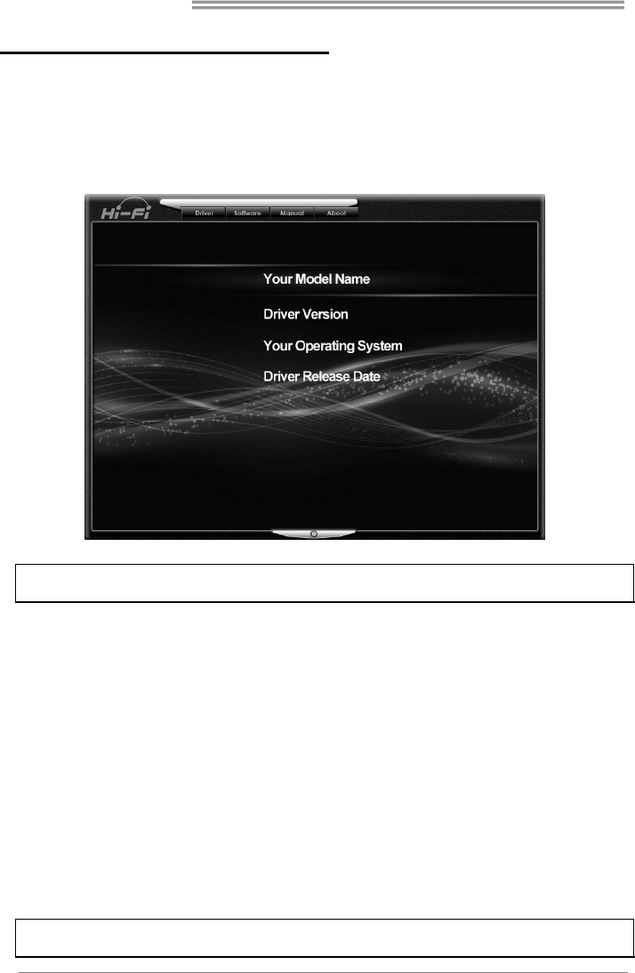
After you installed your operating system, please insert the Fully Setup
Driver DVD into your optical drive and install the driver for better system
performance.
You will see the following window after you insert the DVD
The setup guide will auto detect your motherboard and operating system.
Note: If this window didn’t show up after you insert the Driver DVD, please use file browser to
locate and execute the file SETUP.EXE under your optical drive.
A. Driver Installation
To install the driver, please click on the Driver icon. The setup guide will
list the compatible driver for your motherboard and operating system.
Click on each device driver to launch the installation program.
B. Software Installation
To install the software, please click on the Software icon. The setup guide
will list the software available for your system, click on each software title
to launch the installation program.
C. Manual
Aside from the paperback manual, we also provide manual in the Driver
DVD. Click on the Manual icon to browse for available manual.
Note: You will need Acrobat Reader to open the manual file. Please download the latest version
of Acrobat Reader software from http://www.adobe.com/products/acrobat/readstep2.html

Hi-Fi Z77S/Hi-Fi H77S
45
6.2 EXTRA INFORMATION
CPU Overheated
If the system shutdown automatically after power on system for
seconds, that means the CPU protection function has been activated.
When the CPU is over heated, the motherboard will shutdown
automatically to avoid a damage of the CPU, and the system may not
power on again.
In this case, please double check:
1. The CPU cooler surface is placed evenly with the CPU surface.
2. CPU fan is rotated normally.
3. CPU fan speed is fulfilling with the CPU speed.
After confirmed, please follow steps below to relief the CPU protection
function.
1. Remove the power cord from power supply for seconds.
2. Wait for seconds.
3. Plug in the power cord and boot up the system.
Or you can:
1. Clear the CMOS data.
(See “Close CMOS Header: JCMOS1” section)
2. Wait for seconds.
3. Power on the system again.

Motherboard Manual
46
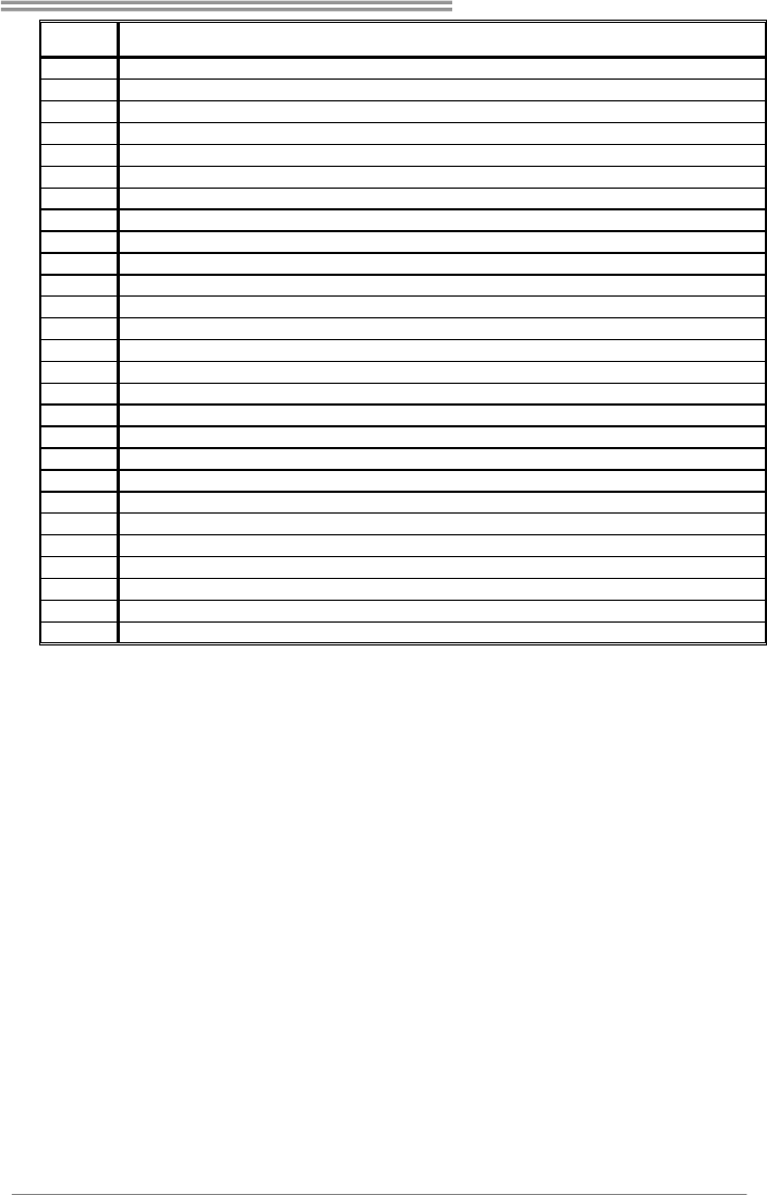
6.3 AMI BIOS POST CODE
Code Description
10 PEI Core is started
11 Pre-memory CPU initialization is started
15 Pre-memory North Bridge initialization is started
19 Pre-memory South Bridge initialization is started
2B Memory initialization. Serial Presence Detect (SPD) data reading
2C Memory initialization. Memory presence detection
2D Memory initialization. Programming memory timing information
2E Memory initialization. Configuring memory
2F Memory initialization (other).
31 Memory Installed
32 CPU post-memory initialization is started
33 CPU post-memory initialization. Cache initialization
34 CPU post-memory initialization. Application Processor(s) (AP) initialization
35 CPU post-memory initialization. Boot Strap Processor (BSP) selection
36 CPU post-memory initialization. System Management Mode (SMM) initialization
37 Post-Memory North Bridge initialization is started
3B Post-Memory North Bridge initialization (North Bridge module specific)
4F DXE IPL is started
60 DXE Core is started
F0 Recovery condition triggered by firmware (Auto recovery)
F1 Recovery condition triggered by user (Forced recovery)
F2 Recovery process started
F3 Recovery firmware image is found
F4 Recovery firmware image is loaded
E0 S3 Resume is stared (S3 Resume PPI is called by the DXE IPL)
E1 S3 Boot Script execution
E2 Video repost
E3 OS S3 wake vector call
60 DXE Core is started
61 NVRAM initialization
62 Installation of the South Bridge Runtime Services
63 CPU DXE initialization is started
68 PCI host bridge initialization
69 North Bridge DXE initialization is started
6A North Bridge DXE SMM initialization is started
70 South Bridge DXE initialization is started
71 South Bridge DXE SMM initialization is started
72 South Bridge devices initialization
78 South Bridge DXE Initialization (South Bridge module specific)
79 ACPI module initialization
90 Boot Device Selection (BDS) phase is started
91 Driver connecting is started
92 PCI Bus initialization is started
93 PCI Bus Hot Plug Controller Initialization
94 PCI Bus Enumeration
95 PCI Bus Request Resources
96 PCI Bus Assign Resources
97 Console Output devices connect
98 Console input devices connect
Hi-Fi Z77S/Hi-Fi H77S
47
Code Description
99 Super IO Initialization
9A USB initialization is started
9B USB Reset
9C USB Detect
9D USB Enable
A0 IDE initialization is started
A1 IDE Reset
A2 IDE Detect
A3 IDE Enable
A4 SCSI initialization is started
A5 SCSI Reset
A6 SCSI Detect
A7 SCSI Enable
A8 Setup Verifying Password
A9 Start of Setup
AB Setup Input Wait
AD Ready To Boot event
AE Legacy Boot event
AF Exit Boot Services event
B0 Runtime Set Virtual Address MAP Begin
B1 Runtime Set Virtual Address MAP End
B2 Legacy Option ROM Initialization
B3 System Reset
B4 USB hot plug
B5 PCI bus hot plug
B6 Clean-up of NVRAM
B7 Configuration Reset (reset of NVRAM settings)

Motherboard Manual
48
6.4 TROUBLESHOOTING
Probable Solution
1. There is no power in the system.
Power LED does not shine; the
fan of the power supply does not
work
2. Indicator light on keyboard does
not shine.
1. Make sure power cable is
securely plugged in.
2. Replace cable.
3. Contact technical support.
System is inoperative. Keyboard lights
are on, power indicator lights are lit,
and hard drives are running.
Using even pressure on both ends of
the DIMM, press down firmly until the
module snaps into place.
System does not boot from a hard disk
drive, but can be booted from optical
drive.
1. Check cable running from disk to
disk controller board. Make sure
both ends are securely plugged
in; check the drive type in the
standard CMOS setup.
2. Backing up the hard drive is
extremely important. All hard
disks are capable of breaking
down at any time.
System only boots from an optical
drive. Hard disks can be read,
applications can be used, but system
fails to boot from a hard disk.
1. Back up data and applications
files.
2. Reformat the hard drive.
Re-install applications and data
using backup disks.
Screen message shows “Invalid
Configuration” or “CMOS Failure.”
Review system’s equipment. Make sure
correct information is in setup.
System cannot boot after user installs a
second hard drive.
1. Set master/slave jumpers
correctly.
2. Run SETUP program and select
correct drive types. Call the drive
manufacturers for compatibility
with other drives.

Hi-Fi Z77S/Hi-Fi H77S
49
This page is intentionally left blank.

Motherboard Manual
50
APPENDIX: SPEC IN OTHER LANGUAGES
GERMAN
Spezifikationen
CPU
Socket 1155
Intel Core i7 / i5 / i3 / Pentium / Celeron
Prozessoren (TDP: 95W)
Unterstützt Execute Disable Bit / Enhanced Intel
SpeedStep® / Intel Architecture-64 / Extended
Memory 64 Technology / Virtualization Technology /
Hyper Threading
Chipsatz Intel Z77 (Hi-Fi Z77S), Intel H77 (Hi-Fi H77S)
Super E/A
IT8728F
Bietet die häufig verwendeten alten Super
E/A-Funktionen.
Low Pin Count-Schnittstelle
Umgebungskontrolle,
Hardware-Überwachung
Lüfterdrehzahl-Controller/-Überwachung
"Smart Guardian"-Funktion von ITE
Arbeitsspeich
er
DDR3 DIMM-Steckplätze x 4
Max. 32GB Arbeitsspeicher
Jeder DIMM unterstützt 512MB/
1GB/2GB/4GB/8GB DDR3.
Dual-Kanal DDR3 Speichermodul
Unterstützt DDR3 1066/1333/1600
Unterstützt DDR3(OC) 1800/2000/2200/2400/2600
Unterstützt DDR3(OC) 1866/2133 (Hi-Fi Z77S)
registrierte DIMMs. ECC DIMMs werden nicht
unterstützt.
SATA 2 & 3 Integrierter Serial ATA-Controller
Datentransferrate bis zu 3.0Gb/s / 6.0Gb/s.
Konform mit der SATA-Spezifikation Version 2.0 / 3.0
Unterstützt RAID 0,1,5,10, SRT
LAN Realtek RTL 8111F 10 / 100 / 1000 Mb/s Auto-Negotiation
Halb-/ Vollduplex-Funktion
HD
Audio-Unters
tützung
ALC892 Unterstützt High-Definition Audio
7.1-Kanal-Audioausgabe, Biostar Hi-Fi
USB3.0 Z77/ H77 Datenübertragungsraten bis zu 600 MB / s
PCI-Steckplatz x2
PCI Express Gen3 x16 Steckplatz x1
PCI Express Gen2 x16 Steckplatz(x4) x1
Steckplätze
PCI Express Gen2 x 1-Steckplatz x2
SATA3-Anschluss x2 Jeder Anschluss unterstützt 1 SATA3-Laufwerk
SATA2-Anschluss x4 Jeder Anschluss unterstützt 1 SATA2-Laufwerk
Fronttafelanschluss x1 Unterstützt die Fronttafelfunktionen
Onboard-Ans
chluss
Front-Audioanschluss x1 Unterstützt die Fronttafel-Audioanschlussfunktion

Hi-Fi Z77S/Hi-Fi H77S
51
Spezifikationen
CPU-Lüfter-Sockel x1
CPU-Lüfterstromversorgungsanschluss (mit Smart
Fan-Funktion)
System-Lüfter-Sockel x2 System-Lüfter-Stromversorgungsanschluss
"CMOS löschen"-Sockel x1
USB2.0-Anschluss x2 Jeder Anschluss unterstützt 2
Fronttafel-USB2.0-Anschlüsse
USB3.0-Anschluss x1 Jeder Anschluss unterstützt 2
Fronttafel-USB3.0-Anschlüsse
Verbraucher-IR Anschluss x1
Serieller Anschluss x1
S/PDIF Ausgangsanschluss x1 Unterstützt die digitale Audioausgabefunktion
Stromanschluss (24-polig) x1
Stromanschluss (8-polig) x1
Rückseiten-E
/A
PS/2-Tastatur/ Maus x1
HDMI-Anschluss x1
VGA-Anschluss x1
DVI-Anschluss x1
LAN-Anschluss x1
USB2.0-Anschluss x4
USB3.0-Anschluss x2
Audioanschluss x6
Platinengröße
220 mm (B) X 305 mm (L) ATX
OS-Unterstüt
zung
Windows XP / Vista / 7/ 8
Biostar behält sich das Recht vor, ohne Ankündigung
die Unterstützung für ein Betriebssystem
hinzuzufügen oder zu entfernen.

Motherboard Manual
52
FRENCH
SPEC
UC
Socket 1155
Processeurs Intel Core i7 / i5 / i3 /
Pentium / Celeron (TDP: 95W)
Prend en charge les technologies d'exécution de bit de
désactivation / Intel SpeedStep® optimisée/
d'architecture Intel 64 / de mémoire étendue 64 / de
virtualisation / Hyper Threading
Chipset Intel Z77 (Hi-Fi Z77S), Intel H77 (Hi-Fi H77S)
Super E/S
IT8728F
Fournit la fonctionnalité de Super E/S
patrimoniales la plus utilisée.
Interface à faible compte de broches
Initiatives de contrôle environnementales,
Moniteur de matériel
Contrôleur /moniteur de vitesse de ventilateur
Fonction "Gardien intelligent" de l'ITE
Mémoire
principale
Fentes DDR3 DIMM x 4
Capacité mémoire maximale de 32 Go
Chaque DIMM prend en charge des DDR3
de 512Mo/1Go/2Go/4Go/8Go
Module de mémoire DDR3 à mode à double voie
Prend en charge la DDR3 1066/1333/1600
Prend en charge la DDR3 (OC) 1800/ 2000/ 2200/
2400/ 2600
Prend en charge la DDR3 (OC) 1866/2133 (H-Fi Z77S)
Les DIMM à registres et DIMM avec code correcteurs
d'erreurs ne sont pas prises en charge
SATA 2 & 3
Contrôleur Serial ATA
intégré :
Taux de transfert jusqu'à 3.0Go/s / 6.0Go/s.
Conforme à la spécification SATA Version 2.0 / 3.0
Prise en charge RAID 0,1,5,10, SRT
LAN Realtek RTL 8111F 10 / 100 / 1000 Mb/s négociation automatique
Half / Full duplex capability
Prise en
charge
audio HD
ALC892 Prise en charge de l'audio haute définition
Sortie audio à 7.1 voies, Biostar Hi-Fi
USB3.0 Z77/ H77 Taux de transfert de données jusqu'à 600 Mo / s
Fente PCI x2
Fente PCI Express Gen3 x16 x1
Fente PCI Express Gen2 x16(x4) x1
Fentes
Fente PCI Express Gen2 x1 x2
Connecteur SATA3 x2 Chaque connecteur prend en charge 1 périphérique
SATA3
Connecteur SATA2 x4 Chaque connecteur prend en charge 1 périphérique
SATA2
Connecteur
embarqué
Connecteur du panneau avant x1 Prend en charge les équipements du panneau avant

Hi-Fi Z77S/Hi-Fi H77S
53
SPEC
Connecteur Audio du panneau avant x1 Prend en charge la fonction audio du panneau avant
Embase de ventilateur UC x1 Alimentation électrique du ventilateur UC (avec fonction
de ventilateur intelligent)
Embase de ventilateur système x2 Alimentation électrique du ventilateur système
Embase d'effacement CMOS x1
Connecteur USB2.0 x2 Chaque connecteur prend en charge 2 ports USB2.0 de
panneau avant
Connecteur USB3.0 x1 Chaque connecteur prend en charge 2 ports USB3.0 de
panneau avant
Connecteur de IR du consommateur x1
Port série x1
Connecteur de sortie S/PDIF x1 Prend en charge la fonction de sortie audio numérique
Connecteur d'alimentation x1
(24 broches)
Connecteur d'alimentation x1
(8 broches)
E/S du
panneau
arrière
Clavier PS/2 Clavier/ Souris x1
Port HDMI x1
Port VGA x1
Port DVI x1
Port LAN x1
Port USB2.0 x4
Port USB3.0 x2
Fiche audio x6
Dimensions
de la carte
220 mm (l) X 305 mm (H) ATX
Support SE Windows XP / Vista / 7/ 8 Biostar se réserve le droit d'ajouter ou de supprimer le
support de SE avec ou sans préavis

Motherboard Manual
54
ITALIAN
SPECIFICA
CPU
Socket 1155
Processore Intel Core i7 / i5 / i3 /
Pentium / Celeron(TDP: 95W)
Supporto di Execute Disable Bit / Enhanced Intel
SpeedStep® / Architettura Intel 64 / Tecnologia
Extended Memory 64 / Tecnologia Virtualization
/ Hyper Threading
Chipset Intel Z77 (Hi-Fi Z77S), Intel H77 (Hi-Fi H77S)
Super I/O
IT8728F
Fornisce le funzionalità legacy Super
I/O usate più comunemente.
Interfaccia LPC (Low Pin Count)
Funzioni di controllo dell’ambiente:
Monitoraggio hardware
Controller / Monitoraggio velocità ventolina
Funzione "Smart Guardian" di ITE
Memoria
principale
Alloggi DIMM DDR3 x 4
Capacità massima della memoria 32GB
Ciascun DIMM supporta DDR3
512MB/1GB/2GB/4GB/8GB
Modulo di memoria DDR3 a canale doppio
Supporto di DDR3 1066/1333/1600
Supporto di DDR3(OC) 1800/ 2000/ 2200/
2400/ 2600
Supporto di DDR3(OC) 1866/2133 (Hi-Fi Z77S)
DIMM registrati e DIMM ECC non sono supportati
SATA 2 & 3
Controller Serial ATA integrato
Velocità di trasferimento dei dati fino a 3.0Gb/s /
6.0Gb/s.
Compatibile specifiche SATA Versione 2.0/3.0
Supporto RAID 0,1,5,10, SRT
LAN Realtek RTL 8111F Negoziazione automatica 10 / 100 / 1000 Mb/s
Capacità Half / Full Duplex
Supporto
audio HD ALC892 Supporto audio High-Definition (HD)
Uscita audio 7.1 canali, Biostar Hi-Fi
USB3.0 Z77/ H77 Velocità di trasferimento dati fino a 600 MB / s
Alloggio PCI x2
Alloggio PCI Express Gen3 x16 x1
Alloggio PCI Express Gen2 x16(x4) x1
Alloggi
Alloggio PCI Express Gen2 x1 x2
Connettore SATA3 x2 Ciascun connettore supporta 1 unità SATA3
Connettore SATA2 x4 Ciascun connettore supporta 1 unità SATA2
Connettore pannello frontale x1 Supporta i servizi del pannello frontale
Connettore audio frontale x1 Supporta la funzione audio pannello frontale
Connettori
su scheda
Collettore ventolina CPU x1 Alimentazione ventolina CPU (con funzione
Smart Fan)

Hi-Fi Z77S/Hi-Fi H77S
55
SPECIFICA
Collettore ventolina sistema x2 Alimentazione ventolina di sistema
Collettore cancellazione CMOS x1
Connettore USB2.0 x2 Ciascun connettore supporta 2 porte USB2.0
pannello frontale
Connettore USB3.0 x1 Ciascun connettore supporta 2 porte USB3.0
pannello frontale
Connettore IR del consumatore x1
Porta seriale x1
Connettore output S/PDIF x1 Supporta la funzione d’output audio digitale
Connettore alimentazione x1
(24 pin)
Connettore alimentazione x1
(8 pin)
I/O
pannello
posteriore
Tastiera/ Mouse PS/2 x1
Porta HDMI x1
Porta VGA x1
Porta DVI x1
Porta LAN x1
Porta USB2.0 x4
Porta USB3.0 x2
Connettore audio x6
Dimension
i scheda
220 mm (larghezza) x 305 mm
(altezza) ATX
Sistemi
operativi
supportati
Windows XP / Vista / 7/ 8
Biostar si riserva il diritto di aggiungere o
rimuovere il supporto di qualsiasi sistema
operativo senza preavviso.

Motherboard Manual
56
SPANISH
Especificación
CPU
Socket 1155
Procesador Intel Core i7 / i5 / i3 / Pentium /
Celeron (TDP: 95W)
Admite Bit de deshabilitación de ejecución / Intel
SpeedStep® Mejorado / Intel Architecture-64 /
Tecnología Extended Memory 64 / Tecnología de
virtualización / Hyper Threading
Conjunto de
chips
Intel Z77 (Hi-Fi Z77S), Intel H77 (Hi-Fi H77S)
Súper E/S
IT8728F
Le ofrece las funcionalidades heredadas de
uso más común Súper E/S.
Interfaz de cuenta Low Pin
Iniciativas de control de entorno,
Monitor hardware
Controlador/monitor de velocidad de ventilador
Función "Guardia inteligente" de ITE
Memoria
principal
Ranuras DIMM DDR3 x 4
Capacidad máxima de memoria de 32GB
Cada DIMM admite DDR de
512MB/1GB/2GB/4GB/8GB
Módulo de memoria DDR3 de canal Doble
Admite DDR3 de 1066/1333/1600
Admite DDR3 de (OC) 1800/ 2000/ 2200/ 2400/
2600
Admite DDR3 de (OC) 1866/2133 (Hi-Fi Z77S)
No admite DIMM registrados o DIMM compatibles
con ECC
SATA 2 & 3 Controlador ATA Serie Integrado
Tasas de transferencia de hasta 3.0 Gb/s / 6.0 Gb/s.
Compatible con la versión SATA 2.0 / 3.0.
Admite RAID 0,1,5,10, SRT
Red Local Realtek RTL 8111F Negociación de 10 / 100 / 1000 Mb/s
Funciones Half / Full dúplex
Soporte de
sonido HD
ALC892 Soporte de sonido de Alta Definición
Salida de sonido de 7.1 canales, Biostar Hi-Fi
USB3.0 Z77/ H77 Tasas de transferencia de datos hasta 600 MB / s
Ranura PCI X2
Ranura PCI Express Gen3 x16 X1
Ranura PCI Express Gen2 x16(x4) X1
Ranuras
Ranura PCI Express Gen2 x 1 X2
Conector SATA3 X2 Cada conector soporta 1 dispositivos SATA3
Conector SATA2 X4 Cada conector soporta 1 dispositivos SATA2
Conector de panel frontal X1 Soporta instalaciones en el panel frontal
Conectores
en placa
Conector de sonido frontal X1 Soporta funciones de sonido en el panel frontal

Hi-Fi Z77S/Hi-Fi H77S
57
Especificación
Cabecera de ventilador de CPU X1 Fuente de alimentación de ventilador de CPU (con
función Smart Fan)
Cabecera de ventilador de sistema X2 Fuente de alimentación de ventilador de sistema
Cabecera de borrado de CMOS X1
Conector USB2.0 X2 Cada conector soporta 2 puertos USB2.0 frontales
Conector USB3.0 X1 Cada conector soporta 2 puertos USB3.0 frontales
Conector de IR del consumidor X1
Puerto serie X1
Conector de salida S/PDIF X1 Soporta función de salida de sonido digital
Conector de alimentación X1
(24 patillas)
Conector de alimentación X1
(8 patillas)
Panel
trasero de
E/S
Teclado/ Ratón PS/2 X1
Puerto HDMI x1
Puerto VGA X1
Puerto DVI X1
Puerto de red local X1
Puerto USB2.0 X4
Puerto USB3.0 X2
Conector de sonido X6
Tam a ñ o d e
la placa
220 mm. (A) X 305 Mm. (H) ATX
Soporte de
sistema
operativo
Windows XP / Vista / 7/ 8 Biostar se reserva el derecho de añadir o retirar el
soporte de cualquier SO con o sin aviso previo.

Motherboard Manual
58
PORTUGUESE
ESPECIFICAÇÕES
CPU
Socket 1155
Processador Intel Core i7 / i5 / i3 /
Pentium / Celeron (TDP: 95W)
Suporta as tecnologias Execute Disable Bit / Enhanced
Intel SpeedStep® / Intel Arquitecture -64 / Extended
Memory 64 / Virtualization / Hyper Threading
Chipset Intel Z77 (Hi-Fi Z77S), Intel H77 (Hi-Fi H77S)
Especificaçã
o Super I/O
IT8728F
Proporciona as funcionalidades mais
utilizadas em termos da especificação
Super I/O.
Interface LPC (Low Pin Count).
Iniciativas para controlo do ambiente
Monitorização do hardware
Controlador/Monitor da velocidade da ventoinha
Função "Smart Guardian" da ITE
Memória
principal
Ranhuras DIMM DDR3 x 4
Capacidade máxima de memória: 32 GB
Cada módulo DIMM suporta uma
memória DDR3 de 512MB/
1GB/2GB/4GB/8GB
Módulo de memória DDR3 de canal duplo
Suporta módulos DDR3 1066/1333/1600
Suporta módulos DDR3 (OC) 1800/ 2000/ 2200/ 2400/
2600
Suporta módulos DDR3 (OC) 1866/2133 (Hi-Fi Z77S)
Os módulos DIMM registados e os DIMM ECC não são
suportados
SATA 2 & 3 Controlador Serial ATA integrado
Velocidades de transmissão de dados até 3.0 Gb/s / 6.0
Gb/s.
Compatibilidade com a especificação SATA versão 2.0 /
3.0.
Suporta as funções RAID 0,1,5,10, SRT
LAN Realtek RTL 8111F Auto negociação de 10 / 100 / 1000 Mb/s
Capacidade semi/full-duplex
Suporte
para áudio
de alta
definição
ALC892 Suporta a especificação High-Definition Audio
Saída de áudio de 7.1 canais, Biostar Hi-Fi
USB3.0 Z77/ H77 Taxas de transferência de dados até 600 MB / s
Ranhura PCI x2
Ranhura PCI Express Gen3 x16 x1
Ranhura PCI Express Gen2 x16(x4) x1
Ranhuras
Ranhura PCI Express Gen2 x 1 x2
Conector SATA3 x2 Cada conector suporta 1 dispositivo SATA3
Conector SATA2 x4 Cada conector suporta 1 dispositivo SATA2
Conector do painel frontal x1 Para suporte de várias funções no painel frontal
Conectores
na placa
Conector de áudio frontal x1 Suporta a função de áudio no painel frontal

Hi-Fi Z77S/Hi-Fi H77S
59
ESPECIFICAÇÕES
Conector da ventoinha da CPU x1 Alimentação da ventoinha da CPU (com a função Smart
Fan)
Conector da ventoinha do sistema x2 Alimentação da ventoinha do sistema
Conector para limpeza do CMOS x1
Conector USB2.0 x2 Cada conector suporta 2 portas USB2.0 no painel frontal
Conector USB3.0 x1 Cada conector suporta 2 portas USB3.0 no painel frontal
Conector de IR do consumidor x1
Porta série x1
Conector de saída S/PDIF x1 Suporta a saída de áudio digital
Conector de alimentação x1
(24 pinos)
Conector de alimentação x1
(8 pinos)
Entradas/S
aídas no
painel
traseiro
Teclado/ Mouse PS/2 x1
Porta HDMI x1
Porta VGA x1
Porta DVI x1
Porta LAN x1
Porta USB2.0 x4
Porta USB3.0 x2
Tomada de áudio x6
Tam an ho
da placa
220 mm (L) X 305 mm (A) ATX
Sistemas
operativos
suportados
Windows XP / Vista / 7/ 8
A Biostar reserva-se o direito de adicionar ou remover
suporte para qualquer sistema operativo com ou sem
aviso prévio.

Motherboard Manual
60
POLISH
SPEC
Procesor
Socket 1155
Procesor Intel Core i7 / i5 / i3 / Pentium /
Celeron (TDP: 95W)
Obsługa Execute Disable Bit / Enhanced Intel
SpeedStep® / Intel Architecture-64 / Extended
Memory 64 Technology / Virtualization Technology /
Hyper Threading
Chipset Intel Z77 (Hi-Fi Z77S), Intel H77 (Hi-Fi H77S)
Pamięć
główna
Gniazda DDR3 DIMM x 4
Maks. wielkość pamięci 32GB
Każde gniazdo DIMM obsługuje moduły
512MB/1GB/2GB/4GB/8GB DDR3
Moduł pamięci DDR3 z trybem podwójnego kanału
Obsługa DDR3 1066/1333/1600
Obsługa DDR3(OC) 1800/ 2000/ 2200/ 2400/ 2600
Obsługa DDR3(OC) 1866/2133 (Hi-Fi Z77S)
Brak obsługi Registered DIMM oraz ECC DIMM
Super I/O
IT8728F
Zapewnia najbardziej powszechne funkcje
Super I/O.
Interfejs Low Pin Count
Funkcje kontroli warunków pracy,
Monitor H/W
Kontroler/Monitor prędkości wentylatora
Funkcja ITE "Smart Guardian"
SATA 2 & 3 Zintegrowany kontroler Serial ATA
Transfer danych do 3.0 Gb/s / 6.0 Gb/s.
Zgodność ze specyfikacją SATA w wersji 2.0 / 3.0.
Obsługa RAID 0,1,5,10, SRT
LAN Realtek RTL 8111F
10 / 100 / 1000 Mb/s z automatyczną negocjacją
szybkości
Działanie w trybie połowicznego / pełnego dupleksu
Obsługa
audio HD
ALC892 Obsługa High-Definition Audio
7.1 kanałowe wyjście audio, Biostar Hi-Fi
USB3.0 Z77/ H77 Cena transferu danych do 600 MB / s
Gniazdo PCI x2
Gniazdo PCI Express Gen3 x16 x1
Gniazdo PCI Express Gen2 x16(x4) x1
Gniazda
Gniazdo PCI Express Gen2 x 1 x2
Złącze SATA3 x2 Każde złącze obsługuje 1 urządzenie SATA3
Złącze SATA2 x4 Każde złącze obsługuje 1 urządzenie SATA2
Złącze panela przedniego x1 Obsługa elementów panela przedniego
Przednie złącze audio x1 Obsługa funkcji audio na panelu przednim
Złącza
wbudowane
Złącze główkowe wentylatora
procesora x1
Zasilanie wentylatora procesora (z funkcją Smart
Fan)

Hi-Fi Z77S/Hi-Fi H77S
61
SPEC
Złącze główkowe wentylatora
systemowego x2
Zasilanie wentylatora systemowego
Złącze główkowe kasowania CMOS x1
Złącze USB2.0 x2 Każde złącze obsługuje 2 porty USB2.0 na panelu
przednim
Złącze USB3.0 x1 Każde złącze obsługuje 2 porty USB3.0 na panelu
przednim
Złącze Konsument IR x1
Port szeregowy x1
Złącze wyjścia S/PDIF x1 Obsługa funkcji cyfrowego wyjścia audio
Złącze zasilania (24 pinowe) x1
Złącze zasilania (8 pinowe) x1
Back Panel
I/O
Klawiatura/ Myszka PS/2 x1
Port HDMI x1
Port VGA x1
Port DVI x1
Port LAN x1
Port USB2.0 x4
Port USB3.0 x2
Gniazdo audio x6
Wymiary
płyty
220 mm (S) X 305 mm (W) ATX
Obsluga
systemu
operacyjne
go
Windows XP / Vista / 7/ 8
Biostar zastrzega sobie prawo dodawania lub
odwoływania obsługi dowolnego systemu
operacyjnego bez powiadomienia.

Motherboard Manual
62
RUSSIAN
СПЕЦ
CPU
(центральн
ый
процессор)
Socket 1155
Процессор Intel Core i7 / i5 / i3 / Pentium /
Celeron (TDP: 95W)
Поддержка технологий Execute Disable Bit /
Enhanced Intel SpeedStep® / Intel Architecture-64
/ Extended Memory 64 Technology / технологии
виртуализация / Hyper Threading
Набор
микросхем
Intel Z77 (Hi-Fi Z77S), Intel H77 (Hi-Fi H77S)
Основная
память
Слоты DDR3 DIMM x 4
Максимальная ёмкость памяти 32 ГБ
Каждый модуль DIMM поддерживает
512МБ/1ГБ/2ГБ/4ГБ/8 ГБ DDR3
Модуль памяти с двухканальным режимом DDR3
Поддержка DDR3 1066/1333/1600
Поддержка DDR3(OC) 1800/ 2000/ 2200/ 2400/
2600
Поддержка DDR3(OC) 1866/2133 (Hi-Fi Z77S)
Не поддерживает зарегистрированные модули
DIMM and ECC DIMM
Super I/O
IT8728F
Обеспечивает наиболее используемые
действующие функциональные
возможности Super I/O.
Интерфейс с низким количеством выводов
Инициативы по охране окружающей среды,
Аппаратный монитор
Регулятор скорости вентилятора/ монитор
Функция ITE "Smart Guardian"
(Интеллектуальная защита)
SATA 2 & 3 Встроенное последовательное устройство
управления ATA
скорость передачи данных до 3.0 гигабит/с /
6.0 гигабит/с.
Соответствие спецификации SATA версия 2.0/3.0
Поддержка RAID 0,1,5,10, SRT
Локальная
сеть
Realtek RTL 8111F
Автоматическое согласование 10 / 100 / 1000
Мб/с
Частичная / полная дуплексная способность
Звуковая
поддержка
жесткого
диска
ALC892 Звуковая поддержка High-Definition
7.1канальный звуковой выход, Biostar Hi-Fi
USB3.0 Z77/ H77 скорости передачи данных до 600 МБ / с
Слот PCI x2
Слот PCI Express Gen3 x16 x1
Слот PCI Express Gen2 x16(x4) x1
Слоты
Слот PCI Express Gen2 x 1 x2
Разъём SATA3 x2 Каждый разъём поддерживает 1 устройство SATA3
Разъём SATA2 x4 Каждый разъём поддерживает 1 устройство SATA2
Встроенны
й разъём Разъём на лицевой панели x1 Поддержка устройств на лицевой панели

Hi-Fi Z77S/Hi-Fi H77S
63
СПЕЦ
Входной звуковой разъём x1
Поддержка звуковых функций на лицевой
панели
Контактирующее приспособление
вентилятора центрального процессора x1
Источник питания для вентилятора центрального
процессора (с функцией интеллектуального
вентилятора)
Контактирующее приспособление
вентилятора системы x2
Источник питания для вентилятора системы
Открытое контактирующее
приспособление CMOS x1
USB2.0-разъём x2
Каждый разъём поддерживает 2 USB2.0-порта на
лицевой панели
USB3.0-разъём x1
Каждый разъём поддерживает 2 USB3.0-порта на
лицевой панели
Разъём едока ИКЫЙ x1
Последовательный порт x1
Разъём вывода для S/PDIF x1 Поддержка вывода цифровой звуковой функции
Разъем питания (24 вывод) x1
Разъем питания (8 вывод) x1
Задняя
панель
средств
ввода-выв
ода
клавиатура/ мышь PS/2 x1
Порт HDMI x1
Порт VGA x1
Порт DVI x1
Порт LAN x1
USB2.0-порт x4
USB3.0-порт x2
Гнездо для подключения
наушников x6
Размер
панели
220 мм (Ш) X 305 мм (В) ATX
Поддержка
OS
Windows XP / Vista / 7/ 8
Biostar сохраняет за собой право добавлять или
удалять средства обеспечения для OS с или без
предварительного уведомления.

Motherboard Manual
64
ARABIC
تﺎﻔﺻاﻮﻤﻟا
تﺎﻴﻨﻘﺗ ﻢﻋﺪﺗExecute Disable Bit / Enhanced Intel
SpeedStep® / Intel Architecture-64 / Extended
Memory 64 Technology / Virtualization Technology /
Hyper Threading
Socket 1155
تﺎﺠﻟﺎﻌﻣIntel Core i7 / i5 / i3 / Pentium /
Celeron ﺑ ددﺮﺘ ﻳ ﻰﻟإ ﻞﺼ (TDP: 95W)
ﺔﺠﻟﺎﻌﻤﻟا ةﺪﺣو
ﺔﻳﺰآﺮﻤﻟا
Intel Z77 (Hi-Fi Z77S), Intel H77 (Hi-Fi H77S) ﺢﺋاﺮﺸﻟا ﺔﻋﻮﻤﺠﻣ
ﺔﺤﺘﻓDDR3 DIMM دﺪﻋ4
ىﻮﺼﻗ ةﺮآاذ ﺔﻌﺳ32 ﺖﻳﺎﺑ ﺎﺠﻴﺟ
ﺔﺤﺘﻓ ﻞآ ﻢﻋﺪﺗDIMM عﻮﻧ ﻦﻣ ةﺮآاذ ﻢﻋﺪﺗ DDR3 ﺔﻌﺳ /512 و ﺖﻳﺎﺑ ﺎﺠﻴﻣ 1/
و2/و 4/و 8 ﺎﺠﻴﺟﺖﻳﺎﺑ
اذ ةﺪﺣوةﺮآة DDR3 ةﺎﻨﻘﻟا ﺔﺟودﺰﻣ
عﻮﻧ ﻦﻣ ةﺮآاﺬﻟا ﻢﻋﺪﺗ DDR3 تﺎﻌﺳ1066 / 1333 / 1600
ﺖﻳﺎﺑ ﺎﺠﻴﻣ
عﻮﻧ ﻦﻣ ةﺮآاﺬﻟا ﻢﻋﺪﺗ DDR3(OC) تﺎﻌﺳ1800 / 2000 /
2200 / 2400 / 2600ﺖﻳﺎﺑ ﺎﺠﻴﻣ
عﻮﻧ ﻦﻣ ةﺮآاﺬﻟا ﻢﻋﺪﺗ DDR3(OC) تﺎﻌﺳ1866 / 2133 ﺎﺠﻴﻣ
ﺖﻳﺎﺑ (Hi-Fi Z77S)
ةﺮآاﺬﻟا ﻖﺋﺎﻗر ﻢﻋﺪﺗ ﻻ DIMM ﻊﻣ ﻖﻓاﻮﺘﺗ ﻻ ﻲﺘﻟا ﻚﻠﺗو ECC
ﺔﻴﺴﻴﺋﺮﻟا ةﺮآاﺬﻟا
ﺔﺌﻴﺒﻟا ﻲﻓ ﻢﻜﺤﺘﻟا ﻞﺋﺎﺳو:
ةﺰﻬﺟﻷا ﺔﻟﺎﺣ ﺔﻓﺮﻌﻤﻟ ﺐﻗاﺮﻣ
ﺔﺣوﺮﻤﻟا ﺔﻋﺮﺳ ﻲﻓ ﺐﻗاﺮﻣ
ﺔﻔﻴﻇو"Smart Guardian" ﻦﻣ ITE
IT8728F
ﺔﻔﻴﻇو ﺮﻓﻮﺗSuper I/O ًﺎ ﻣ ا ﺪ ﺨ ﺘ ﺳ ا ﺮﺜآﻷا .
ﺗﻢﻋﺪ ﺔﻴﻨﻘﺗ Low Pin Count Interface
Super I/O
ﻞﻘﻧ ﺎﻴﺒﻟاتﺎﻧ تﺎﻋﺮﺴﺑ ﻞﺼﺗ ﻰﻟإ 3.0 ﺖﺑﺎﺠﻴﺟ/ﺔﻴﻧﺎﺛ / 6.0 ﺖﺑﺎﺠﻴﺟ/ﺔﻴﻧﺎﺛ.
تﺎﻔﺻاﻮﻤﻟ ﺔﻘﺑﺎﻄﻣSATA راﺪﺻﻹا 2.0 / 3.0.
ﺔﻴﻨﻘﺗ ﻢﻋﺪﺗRAID 0,1,5,10, SRT
ﻢﻜﺤﺘﻣSerial ATAﻞﻣﺎﻜﺘﻣ
SATA 2 & 3
ﻲﺋﺎﻘﻠﺗ ضوﺎﻔﺗ10/100 ﺖﻳﺎﺑ ﺎﺠﻴﻣ /و ﺔﻴﻧﺎﺛ1ﺖﺑ ﺎﺠﻴﺟ/ﺔﻴﻧﺎﺛ
ﻞﻣﺎﻜﻟا جودﺰﻤﻟا ﻞﻘﻨﻟا ﺔﻴﻧﺎﻜﻣإ/ﻲﻔﺼﻨﻟا
Realtek RTL 8111F
ﺔﻴﻠﺧاد ﺔﻜﺒﺷ
ﻦﻣ ﻒﻳﺮﻌﺘﻟا ﻲﻟﺎﻋ تﻮﺼﻟا ﺔﻴﻨﻘﺗ ﻢﻋﺪﺗ
7.1 تﻮﺼﻟا جﺮﺨﻟ تاﻮﻨﻗ , Biostar Hi-Fi
ALC892
ﻲﻟﺎﻋ تﻮﺼﻟا ﻢﻋد
ﻒﻳﺮﻌﺘﻟا
تﻻﺪﻌﻣ ﻞﻘﻧ تﺎﻧﺎﻴﺑ ﻞﺼﺗ ﻰﻟإ 600 ﺎﻐﻴﻣ ﺖﻳﺎﺑ / ﺔﻴﻧﺎﺛ
Z77/ H77
USB3.0
ﺔﺤﺘﻓPCI دﺪﻋ2
ﺔﺤﺘﻓGen3 x16 PCI Express دﺪﻋ1
ﻓﺔﺤﺘGen2 (x4)x16 PCI Express دﺪﻋ1
ﺔﺤﺘﻓPCI Express Gen2 x 1 دﺪﻋ2
تﺎﺤﺘﻔﻟا
ةﺰﻬﺟأ ﻦﻣ ﺪﺣاو ﺬﻔﻨﻣ ﻞآ ﻢﻋﺪﻳSATA3 ﺬﻔﻨﻣSATA3 دﺪﻋ2
ةﺰﻬﺟأ ﻦﻣ ﺪﺣاو ﺬﻔﻨﻣ ﻞآ ﻢﻋﺪﻳSATA2 ﺬﻔﻨﻣSATA2 دﺪﻋ4
ﺔﻴﻣﺎﻣﻷا ﺔﺣﻮﻠﻟا تاﺰﻴﻬﺠﺗ ﻢﻋﺪﻳ ﺔﻴﻣﺎﻣﻷا ﺔﺣﻮﻠﻟا ﺬﻔﻨﻣ دﺪﻋ1
ﺬﻓﺎﻨﻤﻟا ﻰﻠﻋ ﺢﻄﺳ
ﺔﺣﻮﻠﻟا

Hi-Fi Z77S/Hi-Fi H77S
65
تﺎﻔﺻاﻮﻤﻟا
ﺪﻳﺔﻴﻣﺎﻣﻷا ﺔﺣﻮﻠﻟﺎﺑ تﻮﺼﻟا ﺔﻔﻴﻇو ﻢﻋ ﻲﻣﺎﻣﻷا تﻮﺼﻟا ﺬﻔﻨﻣ دﺪﻋ1
ﺔﻔﻴﻇو ﻊﻣ ﺔﺠﻟﺎﻌﻤﻟا ةﺪﺣو ﺔﺣوﺮﻤﻟ ﺔﻗﺎﻄﻟا ﻞﻴﺻﻮﺘﻟSmart Fan ﺔﻳﺰآﺮﻤﻟا ﺔﺠﻟﺎﻌﻤﻟا ةﺪﺣو ﺔﺣوﺮﻣ ﺔﻠﺻو دﺪﻋ1
مﺎﻈﻨﻟا ﺔﺣوﺮﻤﻟ ﺔﻗﺎﻄﻟا ﻞﻴﺻﻮﺘﻟ مﺎﻈﻨﻟا ﺔﺣوﺮﻣ ﺔﻠﺻو دﺪﻋ2
ﺢﺴﻣ ﺔﻠﺻوCMOS دﺪﻋ1
ﻲﺘﺤﺘﻓ ﺬﻔﻨﻣ ﻞآ ﻢﻋﺪﻳUSB2.0ﺔﻴﻣﺎﻣﻷا ﺔﺣﻮﻠﻟﺎﺑ ﺬﻔﻨﻣUSB2.0 دﺪﻋ2
ﻲﺘﺤﺘﻓ ﺬﻔﻨﻣ ﻞآ ﻢﻋﺪﻳUSB3.0ﺔﻴﻣﺎﻣﻷا ﺔﺣﻮﻠﻟﺎﺑ ﺬﻔﻨﻣUSB3.0 دﺪﻋ1
ﺬﻔﻨﻣﺔﻜﻠﻬﺘﺴﻣ ﺖﺤﺗ ﺮﻤﺣﻷا دﺪﻋ1
ﻲﻠﺴﻠﺴﺗ ﺬﻔﻨﻣ دﺪﻋ1
ﻲﻤﻗﺮﻟا تﻮﺼﻟا جﺮﺧ ﺔﻔﻴﻇو ﻢﻋﺪﻳ جﺮﺧ ﺬﻔﻨﻣS/PDIF دﺪﻋ1
ﺔﻗﺎﻄﻟا ﻞﻴﺻﻮﺗ ﺬﻔﻨﻣ)24سﻮﺑد( دﺪﻋ1
ﺻﻮﺗ ﺬﻔﻨﻣ ﺔﻗﺎﻄﻟا ﻞﻴ)8ﺲﻴﺑﺎﺑد( دﺪﻋ1
PS/2ﺮﺗﻮﻴﺒﻤﻜﻠﻟ ﺢﻴﺗﺎﻔﻤﻟا ﺔﺣﻮﻟ /ةرﺎﻔﻟا دﺪﻋ1
ﺬﻓﺎﻨﻣHDMI دﺪﻋ1
ﺬﻓﺎﻨﻣVGA دﺪﻋ1
ﺬﻓﺎﻨﻣDVI دﺪﻋ1
ﺔﻴﻠﺤﻣ لﺎﺼﺗا ﺔﻜﺒﺷ ﺬﻔﻨﻣ دﺪﻋ1
ﺬﻓﺎﻨﻣUSB2.0 دﺪﻋ4
ﺬﻓﺎﻨﻣUSB3.0 دﺪﻋ2
تﻮﺻ ﺲﺒﻘﻣ دﺪﻋ6
ﺬﻓﺎﻨﻣ ﻞﺧد/جﺮﺧ
ﺔﺣﻮﻠﻟا ﺔﻴﻔﻠﺨﻟا
ATX 305 ﻢﻣ)ﺮﻋض (X 220 ﻢﻣ)عﺎﻔﺗرا( ﻢﺠﺣ ﺔﺣﻮﻠﻟا
ﻆﻔﺘﺤﺗ Biostar ﺎﻬﻘﺤﺑ ﻲﻓ ﺔﻓﺎﺿإ وأ ﺔﻟازإ ﻢﻋﺪﻟا يﻷ مﺎﻈﻧ ﻞﻴﻐﺸﺗ رﺎﻄﺧﺈﺑ وأ
نوﺪﺑ رﺎﻄﺧإ. Windows XP / Vista / 7/ 8 ﻢﻋد ﺔﻤﻈﻧأ ﻞﻴﻐﺸﺘﻟا

Motherboard Manual
66
JAPANESE
仕様
CPU
Socket 1155
Intel Core i7 / i5 / i3 / Pentium / Celeron プロ
セッサ (TDP: 95W)
Execute Disable Bit / Enhanced Intel SpeedStep® /
Intel Architecture-64 / Extended Memory 64
Technology / Virtualization Technology / Hyper
Threadingをサポートします
チップセット Intel Z77 (Hi-Fi Z77S), Intel H77 (Hi-Fi H77S)
メインメモリ
DDR3 DIMMスロット x 4
最大メモリ容量32GB
各DIMMは 512MB/1GB/2GB/4GB/8GB DDR3
をサポート
デュアル チャンネルモードDDR3メモリモジュール
DDR3 1066 / 1333 / 1600 をサポート
DDR3(OC) 1800/2000/2200/2400/2600 をサポート
DDR3(OC) 1866/2133 (Hi-Fi Z77S) をサポート
登録済みDIMMとECC DIMMはサポートされません
Super I/O
IT8728F
もっとも一般に使用されるレガシーSuper I/O機
能を採用しています。
低ピンカウントインターフェイス
環境コントロールイニシアチブ、
H/Wモニター
ファン速度コントローラ/ モニター
ITEの「スマートガーディアン」機能
SATA 2 & 3 統合シリアルATAコントローラ
最高3.0 Gb/秒 / 6.0 Gb/秒のデータ転送速度
SATAバージョン2.0 / 3.0仕様に準拠。
RAID 0,1,5,10, SRT のサポート
LAN Realtek RTL 8111F 10 / 100 / 1000 Mb/秒のオートネゴシエーション
半/全二重機能
HDオーディ
オのサポート
ALC892
ハイデフィニションオーディオのサポート
7.1 チャンネルオーディオアウト, Biostar Hi-Fi
USB3.0 Z77/ H77 データ転送速度最大600 MB /秒の
PCIスロット x2
PCI Express Gen3 x16スロット x1
PCI Express Gen2 x16スロット(x4) x1
スロット
PCI Express Gen2 x 1スロット x2
SATA3コネクタ x2 各コネクタは1つのSATA3デバイスをサポートします
SATA2コネクタ x4 各コネクタは1つのSATA2デバイスをサポートします
フロントパネルコネクタ x1 フロントパネル機能をサポートします
フロントオーディオコネクタ x1 フロントパネルオーディオ機能をサポートします
オンボードコ
ネクタ
CPUファンヘッダ x1 CPUファン電源装置(スマートファン機能を搭載)

Hi-Fi Z77S/Hi-Fi H77S
67
仕様
システムファンヘッダ x2 システムファン電源装置
CMOSクリアヘッダ x1
USB2.0コネクタ x2
各コネクタは2つのフロントパネルUSB2.0ポートをサポ
ートします
USB3.0コネクタ x1
各コネクタは2つのフロントパネルUSB3.0ポートをサポ
ートします
消費者IRコネクタ x1
シリアルポート x1
S/PDIFアウトコネクタ x1 デジタルオーディオアウト機能をサポートします
電源コネクタ(24ピン) x1
電源コネクタ(8ピン) x1
背面パネル
I/O
PS/2 キーボード/マウス x1
HDMIポート x1
VGAポート x1
DVI-Dポート x1
LANポート x1
USB2.0ポート x4
USB3.0ポート x2
オーディオジャック x6
ボードサイズ 220 mm (幅) X 305 mm (高さ) ATX
OSサポート Windows XP / Vista / 7/ 8 Biostarは事前のサポートなしにOSサポートを追加または
削除する権利を留保します。
2013/04/23
