Biostar P4M900 Micro 775 Owners Manual P4M90 M7_0226C
2014-07-31
: Biostar Biostar-P4M900-Micro-775-Owners-Manual biostar-p4m900-micro-775-owners-manual biostar pdf
Open the PDF directly: View PDF ![]() .
.
Page Count: 93

P4M900 Micro 775 Setup Manual
FCC Information and Copyright
This equipment has been tested and found to comply with the limits of a Class
B digital device, pursuant to Part 15 of the FCC Rules. These limits are designed
to provide reasonable protec tion against harmful interference in a residential
installation. This equipment generates, uses and can radiate radio frequency
energy and, if not installed and used in accordance with the instructions, may
cause harmful interference to radio communications. There is no guarantee
that interfere nce will not occur in a particular ins tallation.
The ve ndo r makes no represe nta tions or wa rranties with respec t to the
contents here and specially disclaims any implied warranties of merchantability
o r fi tness fo r a ny p u rp ose . F urt he r t he ve ndo r rese rves t he ri ght to rev ise t his
publication and to make changes to the contents here without obligation to
notify any party beforehand.
D uplication of this publication, in part or in whole, is not allowed without first
obtaining the vendor’s approval in writing.
The content of this user’s manual is subject to be changed without notice and
we will not be res ponsible for any mistakes found in this user’s manual. All the
brand and product names are trademarks of their respective companies.

Table of Contents
Chapter 1: INTRODUCTION........................................3
1.1 Before You Start...................................................................3
1.2 Package Checklist................................................................ 3
1.3 Motherboard FeaturesS.........................................................4
1.4 Rear Panel Connectors (for Ver 5.x)....................................... 6
1.5 Rear Panel Connectors (for Ver 6.x).......................................6
1.6 Motherboard Layout (for Ver 5.x)..........................................7
1.7 Motherboard Layout (for Ver 6.x)..........................................8
Chapter 2: Hardware Installation..............................9
2.1 Installing Central Processing Unit (CPU)................................ 9
2.2 Fan Headers........................................................................11
2.3 Installing System Memory.....................................................12
2.4 Connectors and Slots............................................................13
Chapter 3: Headers & Jumpers Setup .....................15
3.1 How to Setup Jumpers..........................................................15
3.2 Detail Settings.....................................................................15
Chapter 4: USEFUL HELP..........................................21
4.1 Driver Installation Note.......................................................21
4.2 Award BIOS Beep Code........................................................22
4.3 Extra Information................................................................22
4.4 Troubleshooting...................................................................24
Chapter 5: WarpSpeeder™ .......................................25
5.1 Introduction........................................................................25
5.2 System Requirement............................................................25
5.3 Installation.........................................................................26
5.4 WarpSpeeder™....................................................................27
Appendencies: SPEC In Other Language ................34
German................................................................................................34
France..................................................................................................36
Italian..................................................................................................38
Spanish................................................................................................40
Portuguese...........................................................................................42
Polish...................................................................................................44
Russian................................................................................................46
Arabic..................................................................................................48
Japanese..............................................................................................50

P4M900 Micro 775
3
CHAPTER 1: INTRODUCTION
1.1 BEFORE YOU START
Tha nk you for choosing our pro duct. Before you sta rt installing the
mo the rboa rd, plea se make sure you fo llo w the ins tructions be low:
Prepare a dry and stable working environment with
s uf ficie nt ligh ting .
Always disconnect the computer from power outlet
be fo re ope ra tion.
Befo re you take the mo the rboa rd ou t f rom a n ti-s ta tic
bag, ground yourself properly by touching any safely
grounde d appliance, or use grounded wrist strap to
remove the static charge.
Avo id tou ch ing the com pone nts o n mo the rboa rd o r the
rear side of the boa rd unless necessary. Hold the board
on the edge , do not try to bend or flex the boa rd.
Do no t lea ve any unfastene d sma ll parts inside the
case after installation. Loose parts will cause short
circuits which ma y damage the equipment.
Keep the computer from dangerous area, such as heat
source, humid air and water.
1.2 PACKAGE CHECKLIST
HDD Cable X 1
User’s Ma nual X 1
Fully Setup Driver CD X 1
Rear I/O Panel for ATX Case X 1
FDD Cable X 1 (optional)
Se ria l ATA Cab le X 1 (op tiona l)
USB 2.0 Cable X1 (optional)
S/PDIF Cable X 1 (optional)
Se ria l ATA Po we r Cab le X 1 (o ptio nal)

Motherboard Manual
4
1.3 MOTHERBOARD FEATURESS
Ver 5.x Ver 6.x
CPU
LGA 77 5
Intel Core2Duo/ Pentium 4 / Pentium D /
Celeron D pr ocessor up to 3.8 GHz
Supports Hyper Threading
/
Ex ecute Disable
Bit/ Enhanced Intel S peedStep®/ Intel
Extended Memory 64 technology
*It is recommended to use
p
rocessors with
95W power co ns umption.
LGA 77 5
Intel Core2Duo/ Pentium 4 / Pentium D /
Celeron D pr ocessor up to 3.8 GHz
Supports Hyper Threading
/
Ex ecute Disable
Bit/ Enhanced Intel S peedStep®/ Intel
Extended Memory 64 technology
*It is recommended to use
p
rocessors with
95W power co ns umption.
FSB 533 / 80 0 / 1 06 6 MHz 533 / 80 0 / 1 06 6 MHz
Chipset VIA P4M900
VIA VT8237A
VIA P4M900
VIA VT8237A
Graphic Chrome9 HC 3D / 2 D Grap hic s
Max Shared Video Memory is 256 MB
Chrome9 HC 3D / 2 D Grap hic s
Max Shared Video Memory is 256 MB
Super I/O
ITE 871 2F
Provides the most commonly used legacy
Super I/O functionality.
Low Pin C ount Interf ace
Environment Control initiatives,
H/W Monitor
Fan Spee d Co ntroller
ITE's "Smart G uardia n" fu nc tion
ITE 871 2F
Provides the most commonly used legacy
Super I/O functionality.
Low Pin C ount Interf ace
Environment Control initiatives,
H/W Monitor
Fan Spee d Co ntroller
ITE's "Smart G uardia n" fu nc tion
Main
Memory
DIMM Slots x 2
Supports D DR2 5 33 / 667
Eac h DIMM sup ports 256/ 512MB/1GB/ 2GB
DDR2
Max Memory Capicity 4GB
Single Channel Mode DDR2 memory
module
Registered DIMM and ECC DIMM is not
supported
DIMM Slots x 2
Supports D DR2 5 33 / 667
Eac h DIMM sup ports 256/ 512MB/1GB/ 2GB
DDR2
Max Memory Capicity 4GB
Single Channel Mode DDR2 memory
module
Registered DIMM and ECC DIMM is not
supported
IDE
Integrated I DE Controller
Ultra DMA 33~133 Bus Master Mode
supports PIO Mo de 0~4,
Integrated I DE Controller
Ultra DMA 33~133 Bus Master Mode
supports PIO Mo de 0~4,
SATA
Integrated Serial ATA Controller
Data transfer rates up to 1.5 Gb/s.
SATA Version 1.0 specification compliant.
Integrated Serial ATA Controller
Data transfer rates up to 1.5 Gb/s.
SATA Version 1.0 specification compliant.

P4M900 Micro 775
5
Ver 5.x Ver 6.x
LAN PHY
Realtek RTL 8201CL
10 / 100 Mb/s auto negotiation
Half / Full duplex capability
Realtek RTL 8201CL
10 / 100 Mb/s auto negotiation
Half / Full duplex capability
Sound
Codec
ALC888
7.1 cha nnels a udio o ut
High- Defi nition Audio s upport
ALC861VD
5.1 cha nnels a udio o ut
High- Defi nition Audio s upport
PCI Express x 16 slot x1 PCI Express x 16 slot x1
PCI Express x 1 slot x1 PCI Express x 1 slot x1 Slots
PCI slot x2 PCI slot x2
Floppy connector x1 Floppy connector x1
IDE Co nnector x2 IDE Co nnector x2
SATA Connector x2 SATA Connector x2
Front Pa nel Co nnec tor x1 Front Pa nel Co nnector x1
Front Audi o Co nnector x1 Front Audi o Co nnector x1
CD-in Co nnec tor x1 CD-in Co nnector x1
S/PDIF out connector x1 S/PDIF out connector x1
CPU Fan hea der x1 CPU Fan hea der x1
System Fan hea der x1 Sys tem Fan hea der x1
Clear CMOS header x1 Clear CMOS header x1
USB connector x2 USB connector x2
Power Connector ( 24pin) x1 Power Connector ( 24pin) x1
On Board
Connector
Power Connector ( 4pin) x1 Power Connector ( 4pin) x1
Back Panel
I/O
PS/2 Keyboard x1
PS/2 Mouse x1
Serial Port x1
Printer Port x1
VGA Port x1
LAN port x1
USB Port x4
Audio Jack x6
PS/2 Keyboard x1
PS/2 Mouse x1
Serial Port x1
Printer Port x1
VGA Port x1
LAN port x1
USB Port x4
Audio Jack x3
Board Size 190 mm (W) x 24 4 mm (L) 190 mm (W) x 24 4 mm (L)
OS
Support
Windows 2000 / XP / VISTA
Biostar Reserves the ri
g
ht to add or remo ve
support for any OS with or without notice.
Windows 2000 / XP / VISTA
Biostar Reserves the ri
g
ht to add or remove
support for any OS with or without notice.
Motherboard Manual
6
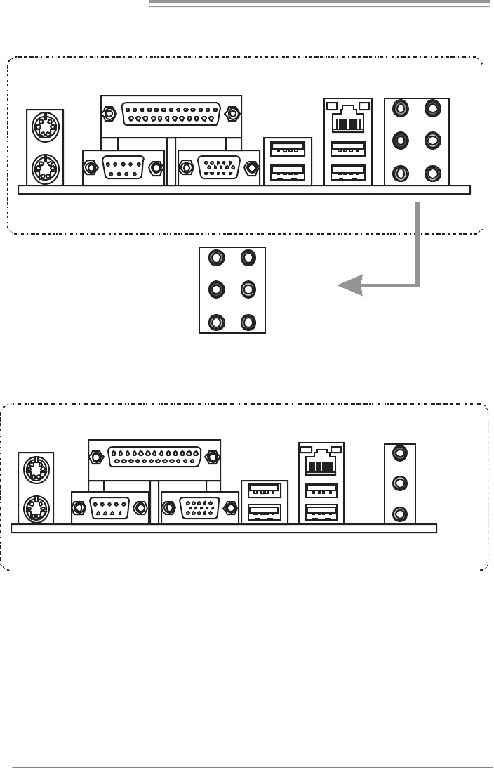
1.4 REAR PANEL CONNECTORS (FOR VER 5.X)
PS/2
Mou se
PS/2
Keyboard USBX2USBX2
LAN
COM1 VGA
Li ne In
Li ne Out
Mic In
Center
Rear
Side
AU DI O JAC K
Printer Port
1.5 REAR PANEL CONNECTORS (FOR VER 6.X)
PS/2
Mouse
PS/2
Keyboard USBX2USBX2
LAN
COM1 VGA
Prin te r P ort Li ne I n /
Surround
Line Out
Mic In 1/
Bass/ Center
Since t he audio c hip s upports High Definiti on Audio Specific ation, t he func tion of eac h audi o
jack c an be defined by sof tware. T he input / out put function of each audio jac k listed above
represents t he def ault s etti ng . However, when c onnecti ng exter nal microphone t o t he audio
port, pleas e us e t he Line In (blue) and Mic In (Pink) audio j ac k.
P4M900 Micro 775
7
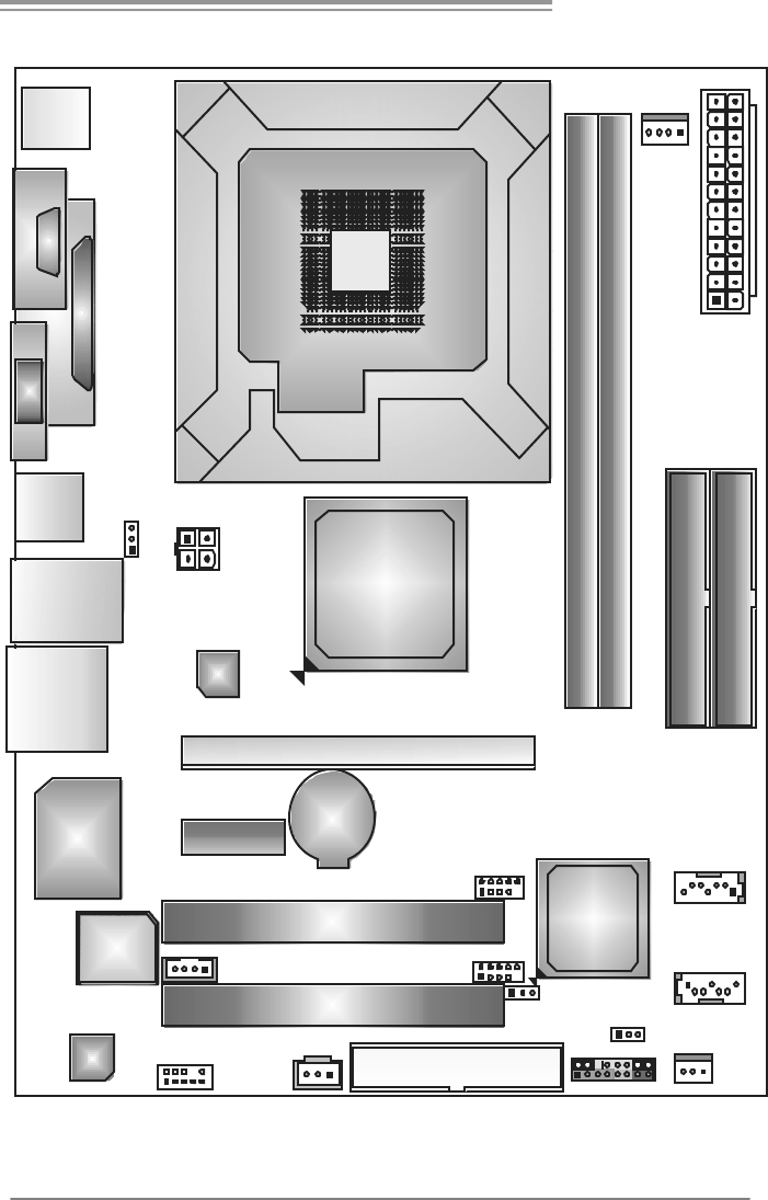
1.6 MOTHERBOARD LAYOUT (FOR VER 5.X)
Super
I/O
DDR2_A1
DDR 2_B1
FDD1
PCI-EX1_1
PCI-EX16
PC I1
PCI2
JPANEL1
JUSB2
JUSB3
JATXPWR1
JCFAN1
JATXPWR2
JSAT A 1
JSATA2
Co de c
JCDIN1
JSFAN1
BAT1
BIOS
VIA
VT8237A
LGA775
CPU1
P4M900
JAUD IO 2
J KBMS 1
JUSB2
JRJ45USB1
COM1
JCOM1
JVGA1
JAUDIO1
JSPDIF_OUT1
IDE1
JC MO S1
LAN
IDE2
JUSBV2
JUSBV1
JP RNT1
Note: represents the 1■st pin.
Motherboard Manual
8
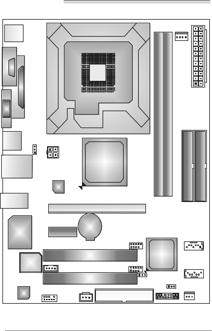
1.7 MOTHERBOARD LAYOUT (FOR VER 6.X)
Super
I/O
DDR2_A1
DDR 2_B1
FDD1
PCI-EX1_1
PCI-EX16
PC I1
PCI2
JPANEL1
JUSB2
JUSB3
JATXPWR1
JCFAN1
JATXPWR2
JSAT A 1
JSATA2
Co de c
JCDIN1
JSFAN1
BAT1
BIOS
VIA
VT8237A
LGA775
CPU1
P4M900
J KBMS 1
JUSB2
JRJ45USB1
COM1
JCOM1
JVGA1
JAUDIO1
IDE1
JC MO S1
LAN
IDE2
JUSBV2
JUSBV1
JP RNT1
JAUD IO 2 JSPDIF_OUT1
Note: represents the 1■st pin.
P4M900 Micro 775
9
CHAPTER 2: HARDWARE INSTALLATION
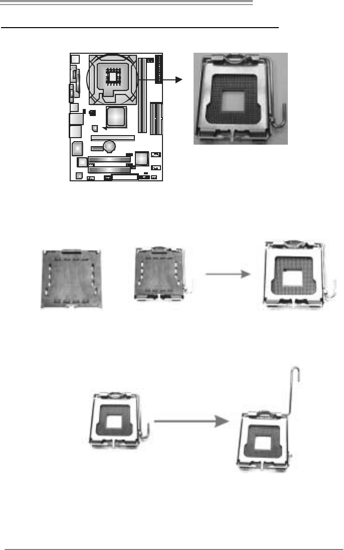
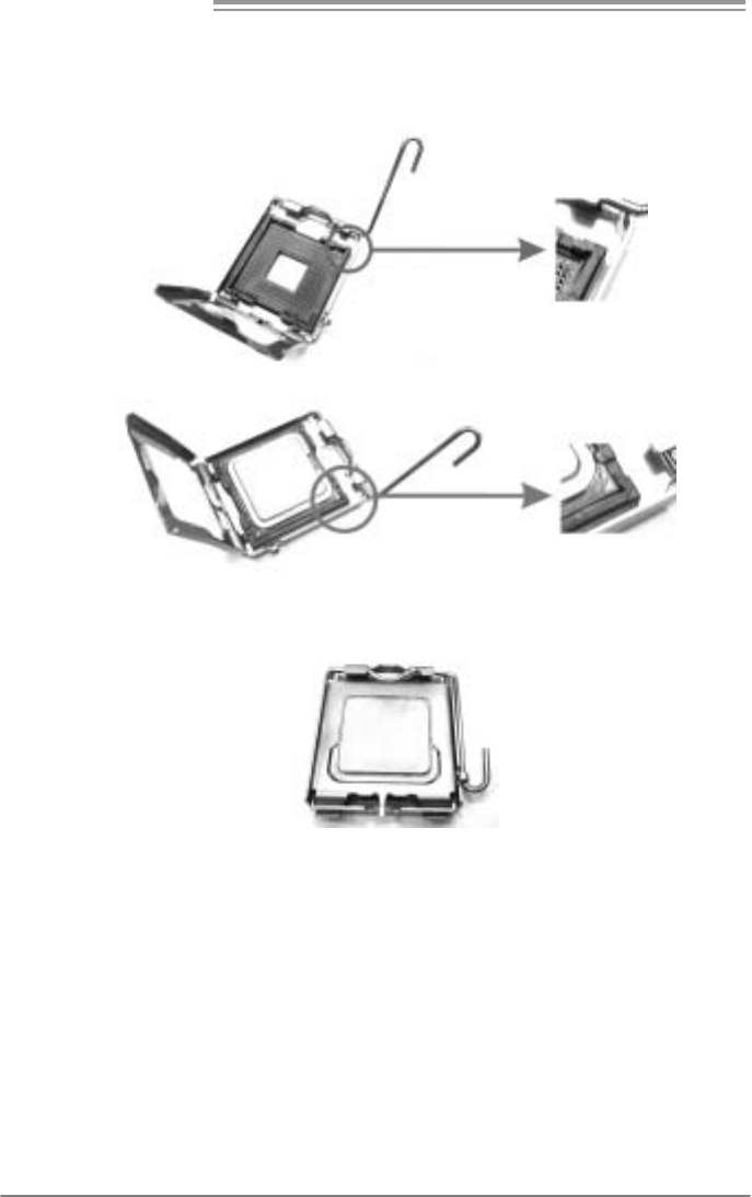
2.1 INSTALLING CENTRAL PROCESSING UNIT (CPU)
Special Notice:
Remove Pin Cap before installation, and make good preservation
for future use. When the CPU is removed, cover the Pin Cap on the
empty socket to ensure pin legs won’t be damaged.
Pin Cap
Step 1: Pull the socket locking lever out from the socket and then raise
the lever up to a 90-degree angle.
Motherboard Manual
10
Step 2: Look for the triangular cut edge on socket, and the golden dot on
CPU should point forwards this triangular cut edge. The CPU will
fit only in the correct orientation.
Step 2-1:
Step 2-2:
Step 3: Hold the CPU down firmly, and then lower the lever to locked
position to complete the installation.
Step 4: Put the CPU Fan and heatsink assembly on the CPU and buckle it
on the retention frame. Connect the CPU FAN power cable into
the JCFAN1. This completes the installation.
P4M900 Micro 775
11
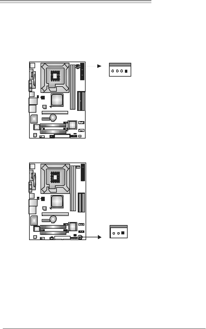
2.2 FAN HEADERS
These fan headers support cooling-fans built in the computer. The fan
cable and connector may be different according to the fan manufacturer.
Connect the fan cable to the connector while matching the black wire to
pin#1.
JCFAN1: CPU Fan Header
Pin
Assignment
1 Ground
2 +12V
3 FAN RPM rate
sense
14
JCFAN1
4 Smart Fan
Control
JSFAN1: System Fan Header
Pin
Assignment
1 Ground
2 +12V
13
JSFAN1
3 FAN RPM rate
sense
Note:
The JSFAN1 s upport 3-pi n head connec tor. When c onnecti ng with wires ont o connec tors,
pleas e note that t he red wire is t he positi ve and s hould be c onnect ed to pin#2, and t he
blac k wire is Ground and s hould be c onnect ed to GND.
Motherboard Manual
12
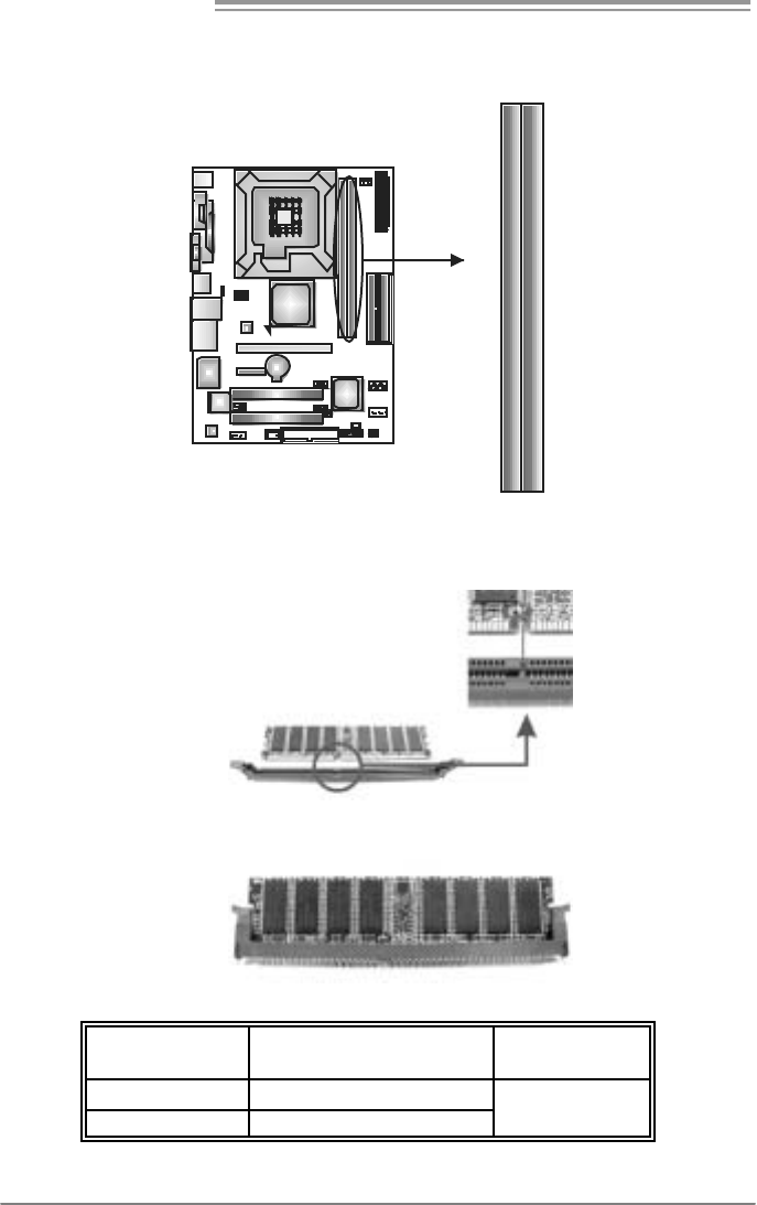
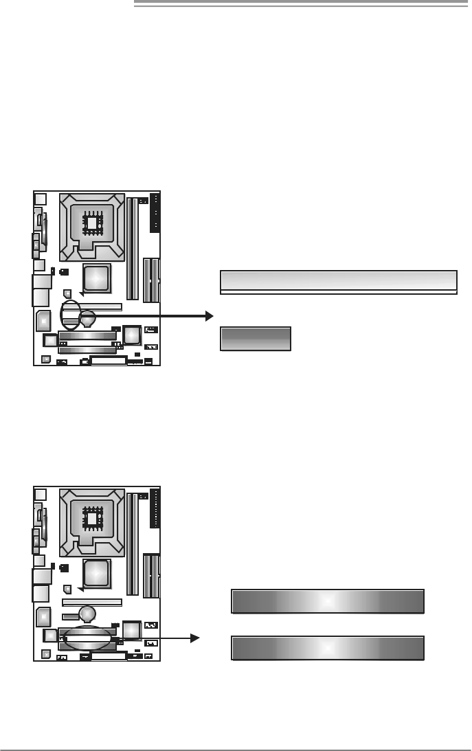
2.3 INSTALLING SYSTEM MEMORY
A. Memory Modules
DDR2 _A1
DDR2 _B1
1. Unlock a DIMM slot by pressing the retaining clips outward. Align a
DIMM on the slot such that the notch on the DIMM matches the
break on the Slot.
2. Insert the DIMM vertically and firmly into the slot until the retaining
chip snap back in place and the DIMM is properly seated.
B. Memory Capacity
DIMM Socket
Location DDR Module To tal Me m o r y
Size
DDR2_A1 256MB/512MB/1GB/2GB
DDR2_B1 256MB/512MB/1GB/2GB
Max is 4GB.
P4M900 Micro 775
13
2.4 CONNECTORS AND SLOTS
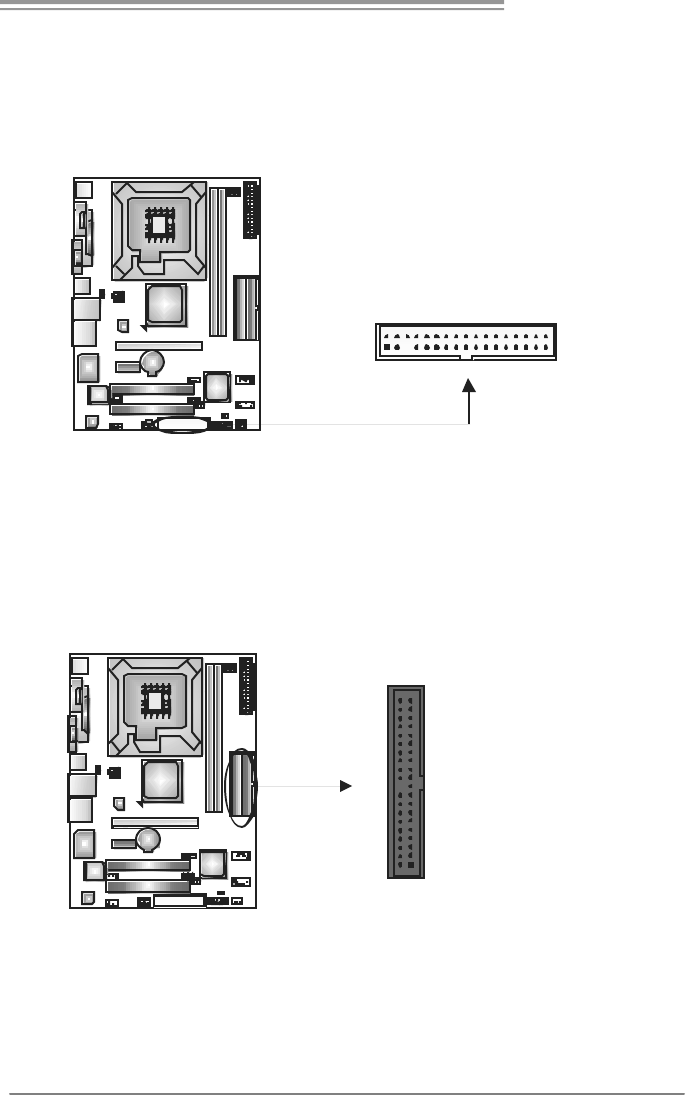
FDD1: Floppy Disk Connector
The motherboard prov ides a standard floppy disk connector that supports 360K,
720K, 1.2M, 1.44M and 2.88M floppy disk ty pes. This connector supports the
prov ided f loppy drive ribbon cables.
34
33
1
2
IDE1/IDE2: Hard Disk Connectors
The motherboard has a 32-bit Enhanced PCI IDE Controller that prov ides PIO
Mode 0~4, Bus Master, and Ultra DMA 33/66/100/133 f unctionality. It has two
HDD connectors IDE1 (primary) and IDE2 (secondary).
The IDE connectors can connect a master and a slav e driv e, so you can
connect up to four hard disk drives. The f irst hard drive should always be
connected to IDE1.
IDE2IDE1
21
3940
Motherboard Manual
14
PCI-EX16: PCI-Express x16 Slot
- PCI-Express 1.0a compliant.
- Maximum theoretical realized bandwidth of 4GB/s simultaneously per
direction, f or an aggregate of 8GB/s totally.
PCI-EX1_1: PCI-Express x1 slots
- PCI-Express 1.0a compliant.
- Data transf er bandwidth up to 250MB/s per direction; 500MB/s in total.
- PCI-Express supports a raw bit-rate of 2.5Gb/s on the data pins.
- 2X bandwidth ov er the traditional PCI architecture.
PCI-EX 16
PCI-EX 1_1
PCI1~PCI2: Peripheral Component Interconnect Slots
This motherboard is equipped with 2 standard PCI slots. PCI stands for
Peripheral Component Interconnect, and it is a bus standard for expansion
cards. This PCI slot is designated as 32 bits.
PCI1
PCI2
P4M900 Micro 775
15
CHAPTER 3: HEADERS & JUMPERS SETUP
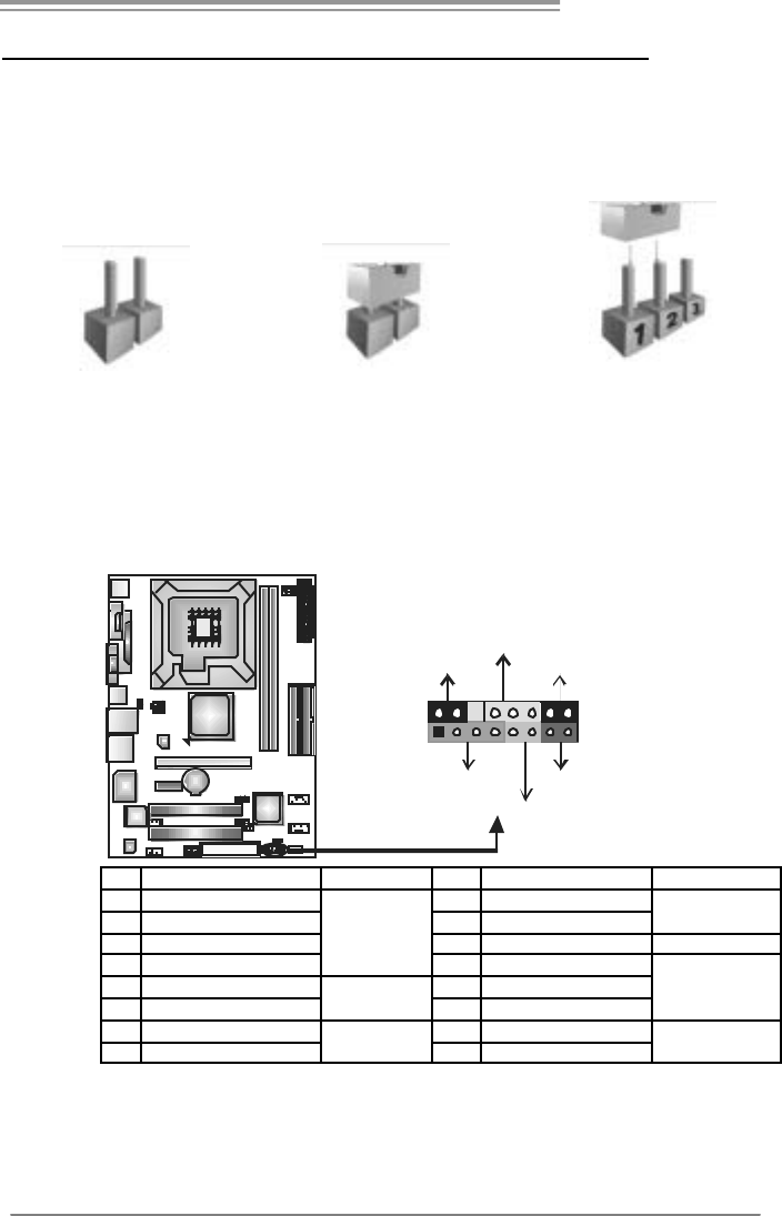
3.1 HOW TO SETUP JUMPERS
The illustration shows how to set up jumpers. When the jumper cap is
placed on pins, the jumper is “close”, if not, that means the jumper is
“open”.
Pin opened Pin closed Pin1-2 closed
3.2 DETAIL SETT INGS
JPANEL1: Front Panel Header
This 16-pin connector includes Power-on, Reset, HDD LED, Power LED, Sleep
button and speaker connection. It allows user to connect the PC case’s f ront
panel switch functions.
18
16
SLP PWR_LED
On/Off
RST
HLED
SPK
++
+
9
-
-
Pin Assignment Function Pin Assignment Functio n
1 +5V 9 Sleep control
2 N/A 10 Ground Sleep button
3 N/A 11 N/A N/A
4 Speaker
Speaker
Connector
12 Power LED (+)
5 HDD LED (+) 13 Power LED (+)
6 HDD LED (-)
Hard drive
LED 14 Power LED (-)
Power LED
7 Ground 15 Power button
8 Reset control Reset button 16 Ground Power-on button
Motherboard Manual
16
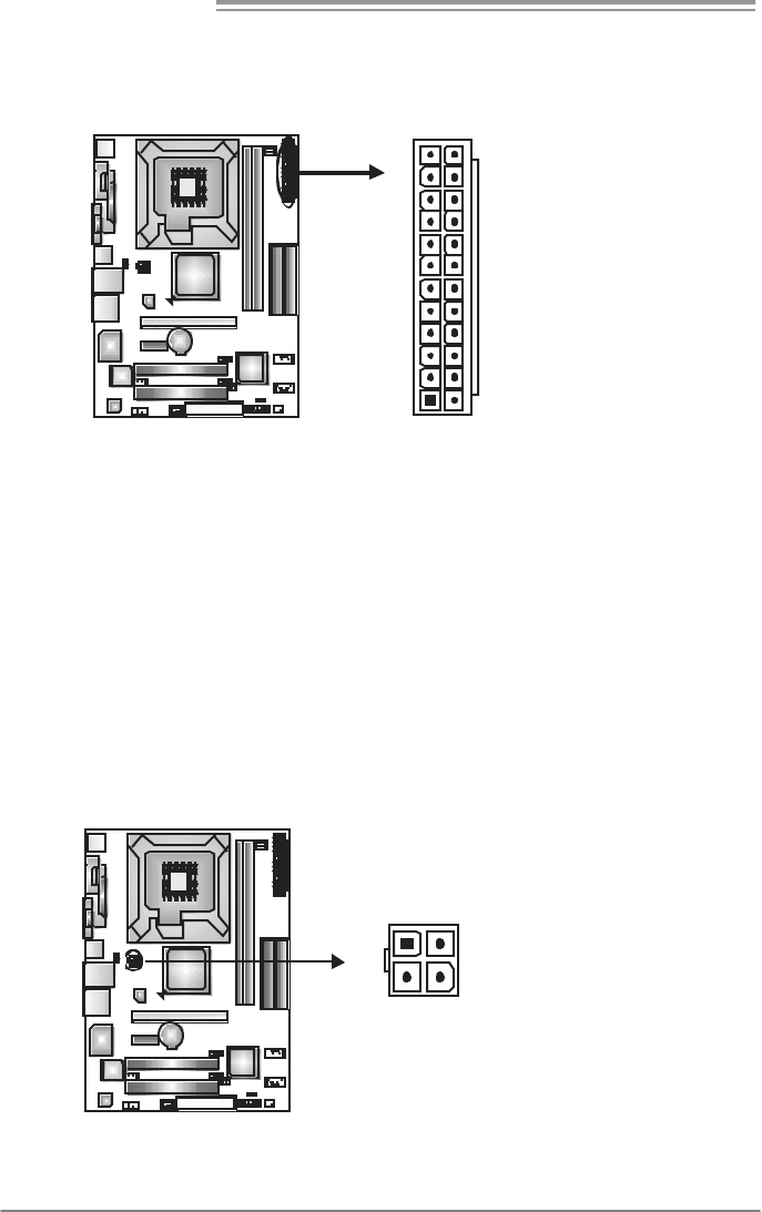
ATX Power Source Connector: JATXPWR1
JATXPWR1 allows user to connect 24-pin power connector on the ATX power
supply.
1
12
13
24
Pin Assignment Pin Assignment
13 +3.3V 1 +3.3V
14 -12V 2 +3.3V
15 Ground 3 Ground
16 PS_ON 4 +5V
17 Ground 5 Ground
18 Ground 6 +5V
19 Ground 7 Ground
20 NC 8 PW_OK
21 +5V 9 Standby Volt age+5V
22 +5V 10 +12V
23 +5V 11 +12V
24 Ground 12 +3.3V
JATXPW R2: ATX Powe r S ou rce C onne ctor
By connecting this connector, it will provide +12V to CPU power circuit.
Pin
Assignment
1 +12V
2 +12V
3 Ground
1
23
4
4 Ground
P4M900 Micro 775
17
JUSB2/JUSB3: Headers for USB 2.0 Ports at Front Panel
This header allows user to connect additional USB cable on the PC f ront panel,
and also can be connected with internal USB devices, like USB card reader.
Pin
Assignment
1 +5V (fused)
2 +5V (fused)
3 USB-
4 USB-
5 USB+
6 USB+
7 Ground
8 Ground
9 Key
19
210
JUSB2
JUSB3
10 NC
JUSBV1/JUSBV2: Powe r Source Heade rs for USB Ports
Pin 1-2 Close:
JUSBV1: +5V for USB ports at JRJ45USB1.
JUSBV2: +5V for USB ports at f ront panel (JUSB2/JUSB3).
Pin 2-3 Close:
JUSBV1: USB ports at JRJ45USB1 are powered by +5V standby v oltage.
JUSBV2: USB ports at front panel (JUSB2/JUSB3) are powered by +5V
standby v oltage.
31
1
3
Pin 1-2 close
1
3
13
JUSBV1
JUSBV2
3
1
1
3
Pin 2-3 close
Note:
In order to s upport this f unction “Power-On s yst em vi a USB devic e,” “JUSBV1/ JUSBV2”
jumper cap should be plac ed on Pin 2-3 indi viduall y.
Motherboard Manual
18
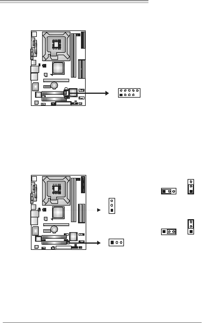
JAUDIO2: Front Panel Audio Header
This header allows user to connect the front audio output cable with the PC f ront
panel. It will disable the output on back panel audio connectors.
Pin Assignment
1 Mic Left in
2 Ground
3 Mic Right in
4 GPIO
5 Right line in
6 Jack Sense
7 Front Sense
8 Key
9 Left line in
10 Jack Sense
19
210
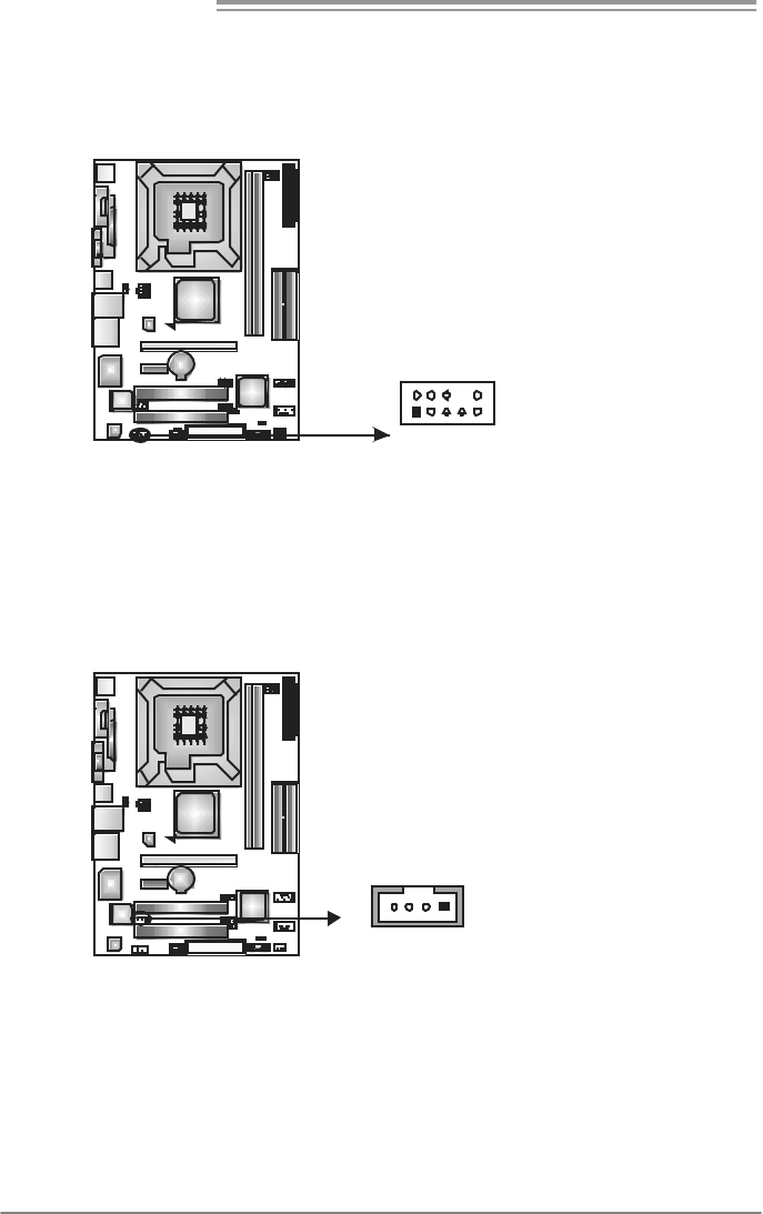
JCDIN1: CD-ROM Audio-in Connector
This connector allows user to connect the audio source f rom the v ariaty dev ices,
like CD-ROM, DVD-ROM, PCI sound card, PCI TV turner card etc.
Pin
Assignment
1 Left Channel Input
2 Ground
3 Ground
14
4 Right Channel Input
P4M900 Micro 775
19
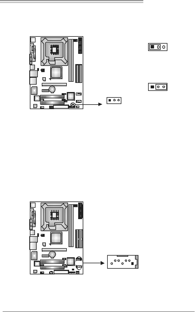
JCMOS1: Clear CMOS Header
By placing the jumper on pin2-3, it allows user to restore the BIOS saf e setting
and the CMOS data, please carefully f ollow the procedures to avoid damaging
the motherboard.
13
Pin 1-2 Close:
Normal Operation (default).
13
13
Pin 2-3 Close:
Clear CMOS data.
※ Clear CMOS Procedures:
1. Remov e AC power line.
2. Set the jumper to “Pin 2-3 close”.
3. Wait for five seconds.
4. Set the jumper to “Pin 1-2 close”.
5. Power on the AC.
6. Reset y our desired password or clear the CMOS data.
JSATA1~JSATA2: Serial ATA Connectors
The motherboard has a PCI to SATA Controller with 2 channels SATA interf ace,
it satisfies the SATA 1.0 spec and with transfer rate of 1.5Gb/s.
Pin
Assignment
1 Ground
2 TX+
3 TX-
4 Ground
5 RX-
6 RX+
14
7
JSATA1
JSATA2
7 Ground
Motherboard Manual
20
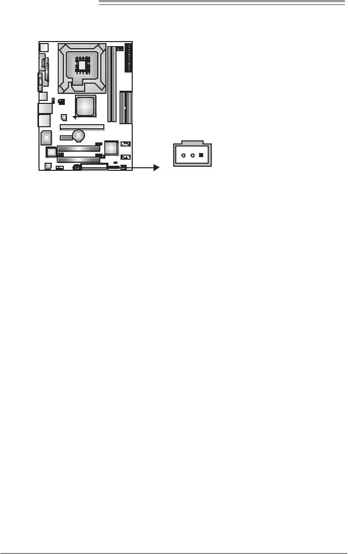
JSPDIF_O UT1: Digital Audio-out Conne ctor
This connector allows user to connect the PCI bracket SPDIF output header.
Pin
Assignment
1 +5V
2 SPDIF_OUT
13
3 Ground
P4M900 Micro 775
21
CHAPTER 4: USEFUL HELP
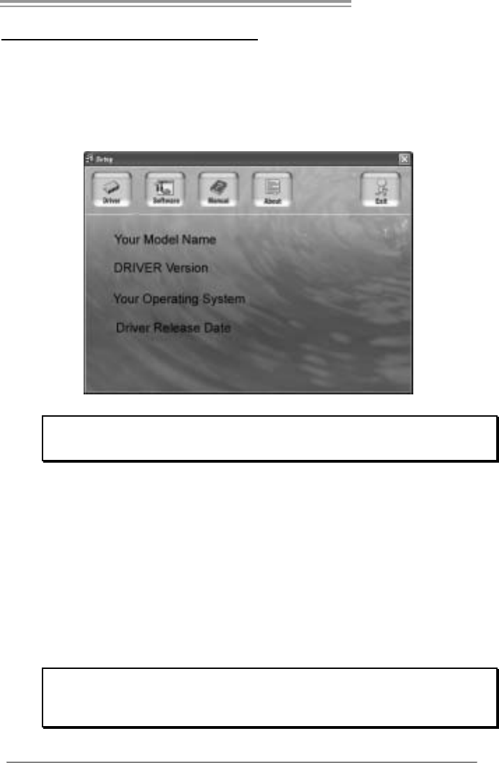
4.1 DRIVER INSTALLATION NOTE
After you installed your operating system, please insert the Fully Setup
Driver CD into your optical drive and install the driver for better system
performance.
You will see the following window after you insert the CD
The setup guide will auto detect your motherboard and operating system.
Note:
If this window didn’t show up aft er you ins ert the Driver CD, please use file browser to
locate and execute the file SETUP.EXE under your optical drive.
A. Driver Installation
To install the driver, please click on the Driver icon. The setup guide will
list the compatible driver for your motherboard and operating system.
Click on each device driver to launch the installation program.
B. Software Installation
To install the software, please click on the Software icon. The setup guide
will list the software available for your system, click on each software title
to launch the installation program.
C. Manual
Aside from the paperback manual, we also provide manual in the Driver
CD. Click on the Manual icon to browse for available manual.
Note:
You will need Acrobat Reader to open the manual file. Please download the latest version
of Acrobat Reader software from
http://www.adobe.com/products/acrobat/readstep2.html
Motherboard Manual
22
4.2 AWARD BIOS BEEP CODE
Beep Sound Meaning
One long beep followed by two short
beeps Video card not found or v ideo card
memory bad
High-low siren sound CPU overheated
System will shut down automatically
One Short beep when system boot-up No error found during POST
Long beeps every other second No DRAM detected or install
4.3 EXT RA INFORMATION
A. BIOS Update
After you fail to update BIOS or BIOS is invaded by virus, the
Boot-Block function will help to restore BIOS. If the following message
is shown after boot-up the system, it means the BIOS contents are
corrupted.
In this Case, please follow the procedure below to restore the BIOS:
1. Make a bootable floppy disk.
2. Download the Flash Utility “AWDFLASH.exe” from the Biostar
website: www.biostar.com.tw
3. Confirm motherboard model and download the respectively BIOS
from Biostar website.
4. Copy “AWDFLASH.exe” and respectively BIOS into floppy disk.
5. Insert the bootable disk into floppy drive and press Enter.
6. System will boot-up to DOS prompt.
7. Type
“Awdflash xxxx.bf/sn/py/r” in DOS prompt.
(xxxx means BIOS name.)
8. System will update BIOS automatically and restart.
9. The BIOS has been recovered and will work properly.

P4M900 Micro 775
23
B. CPU Overheated
If the system shutdown automatically after power on system for
seconds, that means the CPU protection function has been activated.
When the CPU is over heated, the motherboard will shutdown
automatically to avoid a damage of the CPU, and the system may not
power on again.
In this case, please double check:
1. The CPU cooler surface is placed evenly with the CPU surface.
2. CPU fan is rotated normally.
3. CPU fan speed is fulfilling with the CPU speed.
After confirmed, please follow steps below to relief the CPU protection
function.
1. Remove the power cord from power supply for seconds.
2. Wai t for seconds.
3. Plug in the power cord and boot up the system.
Or you can:
1. Clear the CMOS data.
(See “Close CMOS Header: JCMOS1” section)
2. Wai t for seconds.
3. Power on the system agai n.

Motherboard Manual
24
4.4 TROUBLESHOOTING
Probable Solution
1. No power to the system at all
Power light don’t illuminate, fan
inside power supply does not turn
on.
2. Indicator light on key board does
not turn on.
1. Make sure power cable is
securely plugged in.
2. Replace cable.
3. Contact technical support.
System inoperative. Keyboard lights
are on, power indicator lights are lit,
and hard drive is spinning.
Using even pressure on both ends of
the DIMM, press down firmly until the
module snaps into place.
System does not boot from hard disk
driv e, can be booted f rom optical driv e. 1. Check cable running from disk to
disk controller board. Make sure
both ends are securely plugged
in; c hec k t he driv e ty pe in t he
standard CMOS setup.
2. Backing up the hard drive is
extremely important. All hard
disks are capable of breaking
down at any time.
System only boots f rom optical drive.
Hard disk can be read and applications
can be used but booting from hard disk
is impossible.
1. Back up data and applications
files.
2. Ref ormat the hard drive.
Re-install applications and data
using backup disks.
Screen message says “Invalid
Conf iguration” or “CMOS Failure.” Rev iew system’s equipment. Make sur
e
correct information is in setup.
Cannot boot system after installing
second hard driv e. 1. Set master/slave jumpers
correctly.
2. Run SETUP program and select
correct drive types. Call the drive
manuf acturers for compatibility
with other drives.

P4M900 Micro 775
25
CHAPTER 5: WARPSPEEDER™
5.1 INTRODUCTION
[WarpSpeeder™], a new powerful control utility, features three
user-friendly functions including Overclock Manager, Overvoltage
Manager, and Hardware Monitor.
With the Overclock Manager, users can easily adjust the frequency they
prefer or they can get the best CPU performance with just one click. The
Overvoltage Manager, on the other hand, helps to power up CPU core
voltage and Memory voltage. The cool Hardware Monitor smartly indicates
the temperatures, voltage and CPU fan speed as well as the chipset
information. Also, in the About panel, you can get detail descriptions about
BIOS model and chipsets. In addition, the frequency status of CPU,
memory, AGP and PCI along with the CPU speed are synchronically
shown on our main panel.
Moreover, to protect users' computer systems if the setting is not
appropriate when testing and results in system fail or hang,
[WarpSpeeder™] technology assures the system stability by automatically
rebooting the computer and then restart to a speed that is either the
original system speed or a suitable one.
5.2 SYSTEM REQUIREMENT
OS Support: Windows 98 SE, Windows Me, Windows 2000, Windows XP
DirectX: DirectX 8.1 or above. (The Windows XP operating system
includes DirectX 8.1. If you use Windows XP, you do not need to install
DirectX 8.1.)
Motherboard Manual
26
5.3 INSTALLATION
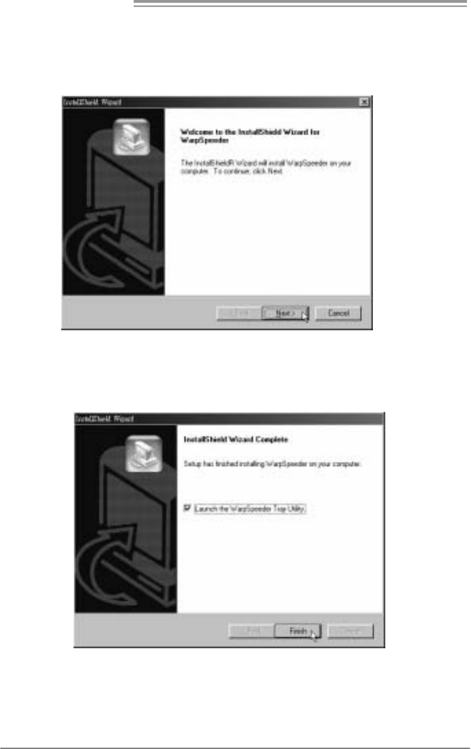
1. Execute the setup execution file, and then the following dialog will pop
up. Please click “Next” button and follow the default procedure to
install.
2. When you see the following dialog in setup procedure, it means setup
is completed. If the “Launch the WarpSpeeder Tray Utility” checkbox
is checked, the Tray Icon utility and [WarpSpeeder™] utility will be
automatically and immediately launched after you click “Finish”
button.
Usage:
The following figures are just only for reference, the screen printed in
this user manual will change according to your motherboard on hand.
P4M900 Micro 775
27
5.4 WARPSPEEDER™
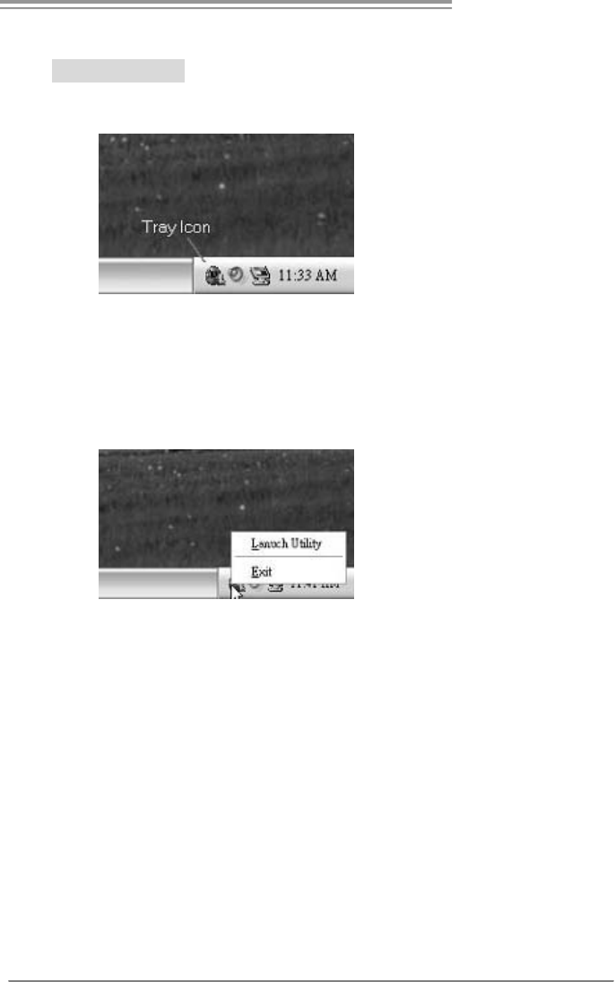
1. Tray Icon:
Whenever the Tray Icon utility is launched, it will display a little tray
icon on the right side of Windows Taskbar.
This utility is responsible for conveniently invoking [WarpSpeeder™]
Utility. You can use the mouse by clicking the left button in order to
invoke [WarpSpeeder™] directly from the little tray icon or you can
right-click the little tray icon to pop up a popup menu as following
figure. The “Launch Utility” item in the popup menu has the same
function as mouse left-click on tray icon and “Exit” item will close
Tray Icon utility if selected.
Motherboard Manual
28
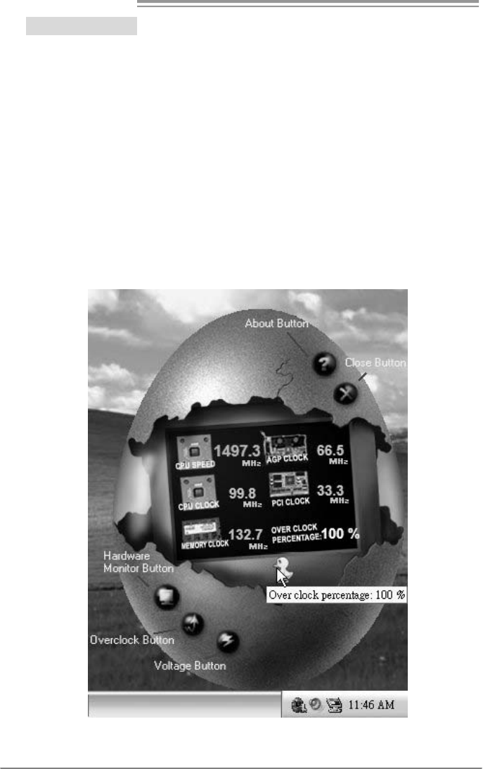
2. Main Panel
If you click the tray icon, [WarpSpeeder™] utility will be invoked.
Please refer to the following figure; the utility’s first window you will
see is Main Panel.
Main Panel contains features as follows:
a. Di spl ay the CPU Speed, CPU external cl ock, Memory clock, AGP cl ock,
and PCI clock information.
b. Contains About, Voltage, Overclock, and Hardware Monitor Buttons for
invoking respective panels.
c. With a user-friendly Status Animation, it can represent 3 overclock
percentage stages:
Man walking→overclock percentage from 100% ~ 110 %
Panther running→overclock percentage from 110% ~ 120%
Car racing→overclock percentage from 120% ~ above
P4M900 Micro 775
29
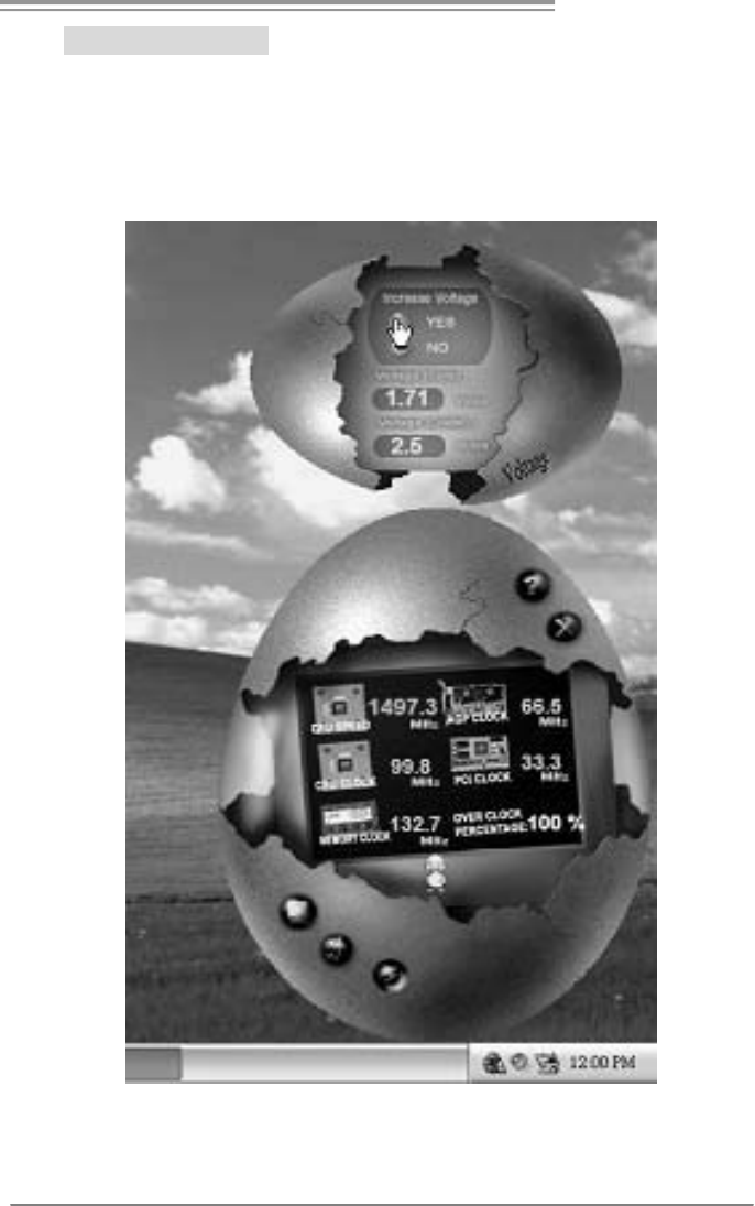
3. Voltage Panel
Click the Voltage button in Main Panel, the button will be highlighted
and the Voltage Panel will slide out to up as the following figure.
In this panel, you can decide to increase CPU core voltage and
Memory voltage or not. The default setting is “No”. If you want to get
the best performance of overclocking, we recommend you click the
option “Yes”.
Motherboard Manual
30
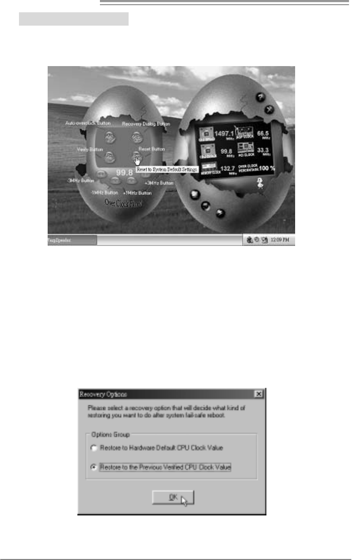
4. Overclock Panel
Click the Overclock button in Main Panel, the button will be
highlighted and the Overclock Panel will slide out to left as the
following figure.
Overclock Panel contains the these features:
a. “–3MHz button”, “-1MHz button”, “+1MHz button”, and “+3MHz button”:
provide user the ability to do real-time overclock adjustment.
Warning:
Manually overclock is potentially dangerous, especially when the
ov erclocking percentage is over 110 %. We strongly recommend you
v erify ev ery speed you overclock by click the Verify button. Or, you can
just click Auto ov erclock button and let [WarpSpeeder™] automatically
gets the best result f or y ou.
b. “Recovery Dialog button”: Pop up the following dialog. Let user select
a restoring way if system need to do a fail-safe reboot.
P4M900 Micro 775
31
c. “Auto-overclock button”: User can click this button and
[WarpSpeeder™] will set the best and stable performance and
frequency automatically. [WarpSpeeder™] utility will execute a
series of testing until system fail. Then system will do fail-safe
reboot by using Watchdog function. After reboot, the
[WarpSpeeder™] utility will restore to the hardware default
setting or load the verified best and stable frequency according
to the Recovery Dialog’s setting.
d. “Verify button”: User can click this button and [WarpSpeeder™]
will proceed a testing for current frequency. If the testing is ok,
then the current frequency will be saved into system registry. If
the testing fail, system will do a fail-safe rebooting. After reboot,
the [WarpSpeeder™] utility will restore to the hardware default
setting or load the verified best and stable frequency according
to the Recovery Dialog’s setting.
Note:
Because the testing programs, invoked in Auto-overclock and Verify,
include DirectDraw, Direct3D and DirectShow tests, the DirectX 8.1 or
newer runtime library is required. And please make sure y our display
card’s color depth is High color (16 bit) or True color( 24/32 bit ) that is
required f or Direct3D rendering.
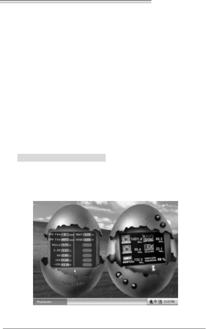
5. Hardware Monitor Panel
Click the Hardware Monitor button in Main Panel, the button will be
highlighted and the Hardware Monitor panel will slide out to left as
the following figure.
In this panel, you can get the real-time status information of your
system. The information will be refreshed every 1 second.
Motherboard Manual
32
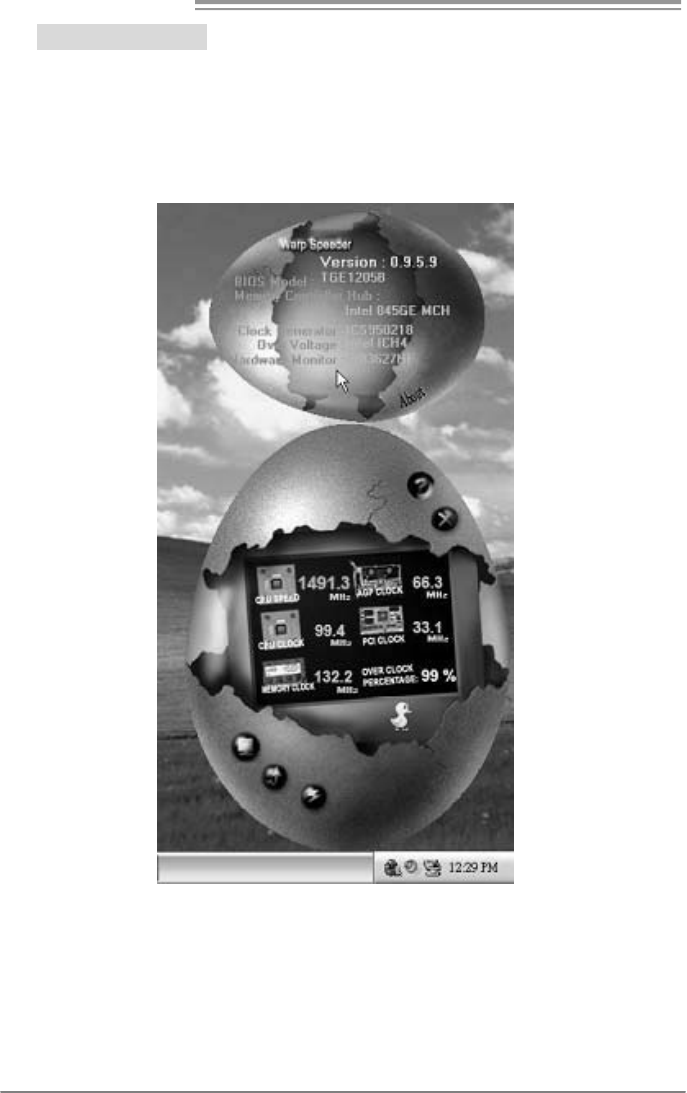
6. About Panel
Click the “about” button in Main Panel, the button will be highlighted
and the About Panel will slide out to up as the following figure.
In this panel, you can get model name and detail information in hints
of all the chipset that are related to overclocking. You can also get
the mainboard’s BIOS model and the Version number of
[WarpSpeeder™] utility.
Note :
Because the overclock, overvoltage, and hardware monitor features
are controlled by several separate chipset, [WarpSpeeder™] divide
these features to separate panels. If one chipset is not on board, the
correl ati ve button in Mai n panel will be di sabled, but will not i nterfere
other panels’ functions. This property can make [WarpSpeeder™]
utility more robust.

P4M900 Micro 775
33
This page is intentionally left blank

Motherboard Manual
34
APPENDENCIES: SPEC IN OTHER LANGUAGE
GERMAN
Ver 5.x Ver 6.x
CPU
LGA 77 5
Intel Core2Duo/ Pentium 4 / Pentium D /
Celeron D Prozessoren mit bis zu 3,8 GHz
Unterstützt Hyper-Threading / Execute
Disable Bit
/
E nha nced I ntel S
p
ee dSte
p
®
/
Intel Architecture-64 / Extended Memory
64 Tech nolog y
*It is recommended to use processors with
95W power co ns umption.
LGA 77 5
Intel Core2Duo/ Pentium 4 / Pentium D /
Celeron D Prozessoren mit bis zu 3,8 GHz
Unterstützt Hyper-Threading / Execute
Disable Bit
/
E nha nced I ntel S
p
ee dSte
p
®
/
Intel Architecture-64 / Extended Memory
64 Tech nolog y
*It is recommended to use
p
rocessors with
95W power co ns umption.
FSB 533 / 80 0 / 1 06 6 MHz 533 / 80 0 / 1 06 6 MHz
Chipsatz VIA P4M900
VIA VT8237A
VIA P4M900
VIA VT8237A
Grafik
Chrome9 HC 3D / 2 D Grap hic s
Max. 256MB gemei nsam be nutzter
Videospeicher
Chrome9 HC 3D / 2 D Grap hic s
Max. 256MB gemei nsam be nutzter
Videospeicher
Super E/A
ITE 871 2F
Bietet die häufi g verwe ndete n alte n Super
E/A-Funktio nen.
Low Pin C ount-Schnittstelle
Umgebu ngskontrolle,
Hardware-Überwachung
Lüfterdrehzahl-Controller
"Smart Guar dian"-Funktion von ITE
ITE 871 2F
Bietet die häufi g verwe ndete n alte n Super
E/A-Funktio nen.
Low Pin C ount-Schnittstelle
Umgebu ngskontrolle,
Hardware-Überwachung
Lüfterdrehzahl-Controller
"Smart Guar dian"-Funktion von ITE
Arbeitsspeic
her
DDR2 DIMM-Steckplätze x 2
Unterstützt DDR2 533 / 667
Jeder DIMM unterstützt
256/512MB/1GB/2GB DDR2.
Max. 4GB Arbeitsspeicher
Ein-Kanal D DR2 S peichermod ul
registrierte DIMMs. ECC DIMMs werden
nicht unterstützt.
DDR2 DIMM-Steckplätze x 2
Unterstützt DDR2 533 / 667
Jeder DIMM unterstützt
256/512MB/1GB/2GB DDR2.
Max. 4GB Arbeitsspeicher
Ein-Kanal D DR2 S peichermod ul
registrierte DIMMs. ECC DIMMs werden
nicht unterstützt.
IDE
Integrierter IDE-Controller
Ultra DMA 33 / 66 / 100 / 133Bus
Master-Modus
Unterstützt PIO-Modus 0~4,
Integrierter IDE-Controller
Ultra DMA 33 / 66 / 100 / 133Bus
Master-Modus
Unterstützt PIO-Modus 0~4,
SATA
Integrierter Serial ATA-Controller
Datentransferr ate bis zu 1.5 Gb/s
Konform mit der SATA-Spezifikation
Vers ion 1.0.
Integrierter Serial ATA-Controller
Datentransferr ate bis zu 1.5 Gb/s
Konform mit der SATA-Spezifikation
Vers ion 1.0.

P4M900 Micro 775
35
Ver 5.x Ver 6.x
LAN PHY
Realtek RTL 8201CL
10 / 100 Mb/s A uto-Negotiation
Halb-/ Vollduplex-Funktion
Realtek RTL 8201CL
10 / 100 Mb/s A uto-Negotiation
Halb-/ Vollduplex-Funktion
Audio-Code
c
ALC888
Unterstützt High-Definition Audio
7.1-Kanal-Au dioausg abe
ALC861VD
Unterstützt High-Definition Audio
5.1-Kanal-Au dioausg abe
PCI-Steckplatz x2 PCI-Steckplatz x2
PCI Expr ess x16 Steckplatz x1 PCI Expr ess x16 Steckplatz x1
Steckplätze
PCI Expr ess x 1-Steckplatz x1 PCI Expr ess x 1-Steckplatz x1
Diskettenlaufwerkanschluss x1 Diskettenlaufwerkanschluss x1
IDE-Anschluss x2 IDE-Anschluss x2
SATA-Anschluss x2 SATA-Anschluss x2
Fronttafelanschluss x1 Fronttafelanschluss x1
Front-Audioanschluss x1 Front-Audioanschluss x1
CD-IN-Anschluss x1 CD-IN-Anschluss x1
S/PDIF-Ausgangsanschluss x1 S/PDIF-Ausgangsanschluss x1
CPU-Lüfter-Sockel x1 CPU-Lüfter-Sockel x1
System-Lüfter-Sockel x1 System-Lüfter-Sockel x1
"CMOS löschen"-Sockel x1 "CMOS löschen"-Sockel x1
USB-Anschluss x2 USB-Anschluss x2
Stromanschluss (24-polig) x1 Stromanschluss (24-polig) x1
Onboard-An
schluss
Stromanschluss (4-polig) x1 Stromanschluss (4-polig) x1
Rückseiten-
E/A
PS/2-Tastatur x1
PS/2-Maus x1
Serieller Anschluss x1
Druckeranschluss x1
VGA-Anschluss x1
LAN-Anschluss x1
USB-Anschluss x4
Audioanschluss x6
PS/2-Tastatur x1
PS/2-Maus x1
Serieller Anschluss x1
Druckeranschluss x1
VGA-Anschluss x1
LAN-Anschluss x1
USB-Anschluss x4
Audioanschluss x3
Platinengr ö
ße. 190 mm (B) X 244 mm (L) 190 mm (B) X 244 mm (L)
OS-Unterst
ützung
Windows 2K / XP / VISTA
Biostar behält sich das Recht vor, ohne
Ankündigung die Unterstützung für ein
Betriebssystem hinzuzufü gen od er zu
entfernen.
Windows 2K / XP / VISTA
Biostar behält sich das Recht vor, ohne
Ankündigung die Unterstützung für ein
Betriebssystem hinzuzufü gen od er zu
entfernen.

Motherboard Manual
36
FRANCE
Ver 5.x Ver 6.x
UC
LGA 77 5
Proces seurs Intel Core 2D uo/ P entium 4 /
Pentium D / Celeron D jusqu'à 3,8 GHz
Prend en charge les technologies
Hyper -Thre adin g / d'ex écution de bit de
désactivation / Intel SpeedStep®
optimisée/ d'architecture Intel 64 / de
mémoire étendue 64
*It is recommended to use
p
rocessors with
95W power co ns umption.
Bus frontal
533 / 80 0 / 1 06 6 MHz 533 / 80 0 / 1 06 6 MHz
Chipset VIA P4M900
VIA VT8237A
VIA P4M900
VIA VT8237A
Graphi que
s
Chrome9 HC 3D / 2 D Grap hic s
Mémoire vidéo partagée maximale de 256
Mo
Chrome9 HC 3D / 2 D Grap hic s
Mémoire vidéo partagée maximale de 256
Mo
Super E/S
ITE 871 2F
Fournit la fo nctionnalité de Super E/S
patrimoniales la plus utilisée.
Interface à faible compte de broc hes
Initiatives de contrôle environnementales,
Moniteur de matériel
Contrôleur de vitess e de ventilateur
Fonction "Gardien i ntelligent" de l'ITE
ITE 871 2F
Fournit la fo nctionnalité de Super E/S
patrimoniales la plus utilisée.
Interface à faible compte de broc hes
Initiatives de contrôle environnementales,
Moniteur de matériel
Contrôleur de vitess e de ventilateur
Fonction "Gardien i ntelligent" de l'ITE
Mémoire
principale
Fentes DDR 2 DIMM x 2
Prend en charge la DDR 2 533 / 667
Chaque DIMM pren d e n ch arge des DDR2
de 256 Mo /512 Mo / 1Go / 2 Go
Capacité mémoire maximale de 4 Go
Module de mémoire DDR2 à mode à simple
voie
Les DIMM à registres et DIMM sans code
correcteurs d'erreurs sont pas prises en
charge
Fentes DDR 2 DIMM x 2
Prend en charge la DDR 2 533 / 667
Chaque DIMM pren d e n ch arge des DDR2
de 256 Mo /512 Mo / 1Go / 2 Go
Capacité mémoire maximale de 4 Go
Module de mémoire DDR2 à mode à simple
voie
Les DIMM à registres et DIMM sans code
correcteurs d'erreurs sont pas prises en
charge
IDE
Contrôleur IDE intégr é
Mode
p
ri nci
p
ale de Bus Ultra DMA 33
/
66
/
100 / 13 3
Prend en charge le mode PIO 0~4,
Contrôleur IDE intégr é
Mode
p
ri nci
p
ale de Bus Ultra DMA 33
/
66
/
100 / 13 3
Prend en charge le mode PIO 0~4,
SATA
Contrôleur Serial ATA intégré :
Taux de transfert jusqu'à 1.5 Go/s.
Conforme à la spécification SATA Version
1.0
Contrôleur Serial ATA intégré :
Taux de transfert jusqu'à 1.5 Go/s.
Conforme à la spécification SATA Version
1.0

P4M900 Micro 775
37
Ver 5.x Ver 6.x
LAN PHY
Realtek RTL 8201CL
10 / 100 Mb/s négociation automatique
Half / Full duplex capability
Realtek RTL 8201CL
10 / 100 Mb/s négociation automatique
Half / Full duplex capability
Codec
audio
ALC888
Prise en c harge de l'au dio haute dé finition
Sortie audio à 7.1 voies
ALC861VD
Prise en c harge de l'au dio haute dé finition
Sortie audio à 5.1 voies
Fente PCI x2 Fente PCI x2
Slot PCI Express x16 x1 Slot PCI Express x16 x1
Fentes
Slot PCI Express x 1 x1 Slot PCI Express x 1 x1
Connecteur de disqu ette x1 Connecteur de disquette x1
Connecteur IDE x2 Connec teur IDE x2
Connecteur SATA x2 Connec teur SATA x2
Connecteur du pa nne au avant x1 Connecteur du pa nne au avant x1
Connecteur Audio d u p ann eau ava nt x1 Connecteur Audio d u p ann eau ava nt x1
Connecteur d'entré e CD x1 Connecteur d'entré e CD x1
Connecteur de sortie S/PDIF x1 Connecteur de sortie S/PDIF x1
Embase d e ve ntilateur UC x1 Embase d e ve ntilateur UC x1
Embase de ventilateur système x1 Embase de ventilateur système x1
Embase d'e ffacement CMOS x1 Embase d'e ffacement CMOS x1
Connecteur USB x2 Connecteur USB x2
Connecteur d'alimentation x1
(24 broches)
Connecteur d'alimentation x1
(24 broches)
Connecteu
r
embarqué
Connecteur d'alimentatio n x1
(4 br oches)
Connecteur d'alimentatio n x1
(4 br oches)
E/S d u
pann eau
arrière
Clavier PS/2 x1
Souris PS/2 x1
Port série x1
Port d'imprimante x1
Port VGA x1
Port LAN x1
Port USB x4
Fiche audio x6
Clavier PS/2 x1
Souris PS/2 x1
Port série x1
Port d'imprimante x1
Port VGA x1
Port LAN x1
Port USB x4
Fiche audio x3
Dimension
s de la
carte
190 mm (l) X 244 mm (H) 190 mm (l) X 244 mm (H)
Support
SE
Windows 2K / XP / VISTA
Biostar se réserve le droit d'ajouter ou de
supprimer le supp ort de SE avec o u sa ns
préavis.
Windows 2K / XP / VISTA
Biostar se réserve le droit d'ajouter ou de
supprimer le supp ort de SE avec o u sa ns
préavis.

Motherboard Manual
38
ITALIAN
Ver 5.x Ver 6.x
CPU
LGA 77 5
Processore Intel Core2Duo/ Pentium 4 /
Pentium D / Celeron D fino a 3.8 GHz
Supporto di Hyper -T hreadi ng / Execute
Disable Bit
/
E nha nced I ntel S
p
ee dSte
p
®
/
Architettura Intel 64
/
Tecnolo
g
ia Extended
Memory 64
*It is recommended to use
p
rocessors with
95W power co ns umption.
LGA 77 5
Processore Intel Core2Duo/ Pentium 4 /
Pentium D / Celeron D fino a 3.8 GHz
Supporto di Hyper -T hreadi ng / Execute
Disable Bit
/
E nha nced I ntel S
p
ee dSte
p
®
/
Architettura Intel 64
/
Tecnolo
g
ia Extended
Memory 64
*It is recommended to use
p
rocessors with
95W power co ns umption.
FSB 533 / 80 0 / 1 06 6 MHz 533 / 80 0 / 1 06 6 MHz
Chipset VIA P4M900
VIA VT8237A
VIA P4M900
VIA VT8237A
Grafica
Chrome9 HC 3D / 2 D Grap hic s
La memoria vi deo condivisa massima è di
256MB
Chrome9 HC 3D / 2 D Grap hic s
La memoria vi deo condivisa massima è di
256MB
Super I/O
ITE 871 2F
Fornisce le funzionalità legacy Super I/O
usate più comunemente.
Interfaccia LPC (Low Pin Count)
Funzioni di controllo dell’ambiente:
Monitoraggio hardware
Controller velocità ventolina
Funzione "Smart G uardi an" di I TE
ITE 871 2F
Fornisce le funzionalità legacy Super I/O
usate più comunemente.
Interfaccia LPC (Low Pin Count)
Funzioni di controllo dell’ambiente:
Monitoraggio hardware
Controller velocità ventolina
Funzione "Smart G uardi an" di I TE
Memoria
principale
Alloggi DIMM DDR 2 x 2
Supporto di DDR2 533 / 667
Ciascun DIMM su pporta DDR 2 25 6MB
/512MB / 1GB / 2GB
Capacità massima della memoria 4GB
Modulo di memoria D DR2 a can ale singolo
DIMM registrati e DIMM ECC non sono
supportati
Alloggi DIMM DDR 2 x 2
Supporto di DDR2 533 / 667
Ciascun DIMM su pporta DDR 2 25 6MB
/512MB / 1GB / 2GB
Capacità massima della memoria 4GB
Modulo di memoria D DR2 a can ale singolo
DIMM registrati e DIMM ECC non sono
supportati
IDE
Controller IDE i ntegrato
Modalità Bus Master Ultra DMA 33 / 66 /
100 / 1 33
Supporto modalità PIO Mode 0- 4
Controller IDE i ntegrato
Modalità Bus Master Ultra DMA 33 / 66 /
100 / 1 33
Supporto modalità PIO Mode 0- 4
SATA
Controller Serial ATA integrato
Velocità di trasferimento dei dati fi no a 1. 5
Gb/s.
Compatibile specifiche SATA Versione 1.0.
Controller Serial ATA integrato
Velocità di trasferimento dei dati fi no a 1. 5
Gb/s.
Compatibile specifiche SATA Versione 1.0.

P4M900 Micro 775
39
Ver 5.x Ver 6.x
LAN PHY
Realtek RTL 8201CL
Negoziazione automatica 10 / 10 0 Mb /s
Capacità Half / Full Duplex
Realtek RTL 8201CL
Negoziazione automatica 10 / 10 0 Mb /s
Capacità Half / Full Duplex
Codec
audio
ALC888
Supporto audio High-Definition (HD)
Uscita audio 7.1 canali
ALC861VD
Supporto audio High-Definition (HD)
Uscita audio 5.1 canali
Alloggio PCI x2 Alloggio PCI x2
Alloggio PCI Ex press x1 6 x1 Alloggio PCI Ex press x16 x1 Alloggi
Alloggio PCI Ex press x1 x1 Alloggio PCI Ex press x1 x1
Connettore flo ppy x1 Connettore flo ppy x1
Connettore IDE x2 Connettore IDE x2
Connettore SATA x2 Connettore SATA x2
Connettore pa nnello fro ntale x1 Connettore pa nnello fro ntale x1
Connettore audio frontale x1 Connettore audio frontale x1
Connettore CD-in x1 Connettore CD-in x1
Connettore output SPDIF x1 Connettore output SPDIF x1
Collettore ventolina CPU x1 Collettore ventolina CPU x1
Collettore ventolina sistema x1 Collettore ventolina sistema x1
Collettore cancellazione CMOS x1 Collettore cancellazione CMOS x1
Connettore USB x2 Connettore USB x2
Connettore alimentazione x1
(24 pin)
Connettore alimentazione x1
(24 pin)
Connettori
su scheda
Connettore alimentazione x1
(4 pi n)
Connettore alimentazione x1
(4 pi n)
I/O
pannello
posteriore
Ta s t i e r a P S / 2 x 1
Mouse PS/2 x1
Porta seriale x1
Porta stampante x1
Porta VGA x1
Porta LAN x1
Porta USB x4
Connettore au dio x6
Ta s t i e r a P S / 2 x 1
Mouse PS/2 x1
Porta seriale x1
Porta stampante x1
Porta VGA x1
Porta LAN x1
Porta USB x4
Connettore au dio x3
Dimension
i scheda 19 0 mm (largh ez za) x 24 4 mm (altezza) 19 0 mm (largh ezza) x 24 4 mm (altezza)
Sistemi
operativi
supportati
Windows 2K / XP / VISTA
Biostar si riserva il diritto di aggiungere o
rimuovere il supporto di qualsiasi sistema
operativo se nza pre avviso.
Windows 2K / XP / VISTA
Biostar si riserva il diritto di aggiungere o
rimuovere il supporto di qualsiasi sistema
operativo se nza pre avviso.

Motherboard Manual
40
SPANISH
Ver 5.x Ver 6.x
CPU
LGA 77 5
Procesador I ntel Core 2Duo/ P entium 4 /
Pentium D / Celeron D hasta 3,8 GHz
Admite Hyper -T hreadi ng / Bit d e
deshabilitación de ejecución / Intel
SpeedStep® Me jora do / Intel
Architecture-64 / Tecnología Extended
Memory 64
*It is recommended to use
p
rocessors with
95W power co ns umption.
FSB 533 / 80 0 / 1 06 6 MHz 533 / 80 0 / 1 06 6 MHz
Conjunto
de chips
VIA P4M900
VIA VT8237A
VIA P4M900
VIA VT8237A
Gráficos
Chrome9 HC 3D / 2 D Grap hic s
Memoria máxima de vídeo compartida de
256MB
Chrome9 HC 3D / 2 D Grap hic s
Memoria máxima de vídeo compartida de
256MB
Súper E/S
ITE 871 2F
Le ofrece las funcionalidades heredadas de
uso más común Súper E/S.
Interfaz de cuenta Low Pin
Iniciativas de control de entor no,
Monitor hardware
Controlador de velocida d d e ve ntilador
Función "Guardia inteligente" de ITE
ITE 871 2F
Le ofrece las funcionalidades heredadas de
uso más común Súper E/S.
Interfaz de cuenta Low Pin
Iniciativas de control de entor no,
Monitor hardware
Controlador de velocida d d e ve ntilador
Función "Guardia inteligente" de ITE
Memoria
principal
Ranuras DIMM DDR 2 x 2
Admite DDR2 de 533 / 667
Cada DIMM admite DDR de 25 6MB
/
51 2MB
/1GB / 2GB
Capacidad máxima de memoria de 4GB
Módulo de memoria DDR2 de canal Sencillo
No admite DIMM registrados o DIMM
compatibles con ECC
Ranuras DIMM DDR 2 x 2
Admite DDR2 de 533 / 667
Cada DIMM admite DDR de 25 6MB
/
51 2MB
/1GB / 2GB
Capacidad máxima de memoria de 4GB
Módulo de memoria DDR2 de canal Sencillo
No admite DIMM registrados o DIMM
compatibles con ECC
IDE
Controlador IDE inte grado
Modo bus maestro Ultra DMA 33 / 66 / 100
/ 133
Soporte los Mo dos PIO 0~4,
Controlador IDE inte grado
Modo bus maestro Ultra DMA 33 / 66 / 100
/ 133
Soporte los Mo dos PIO 0~4,
SATA
Controlador ATA Serie Integrado
Tasas de transferencia de hasta 1.5 Gb/s.
Compatible con la versión SATA 1.0.
Controlador ATA Serie Integrado
Tasas de transferencia de hasta 1.5 Gb/s.
Compatible con la versión SATA 1.0.

P4M900 Micro 775
41
Ver 5.x Ver 6.x
Red Local
Realtek RTL 8201CL
Negociación de 10 / 10 0 Mb/s
Funciones Half / Full dúplex
Realtek RTL 8201CL
Negociación de 10 / 10 0 Mb/s
Funciones Half / Full dúplex
Códecs de
sonido
ALC888
Soporte d e soni do de Alta Defi nición
Salida de sonido de 7.1 canales
ALC861VD
Soporte d e soni do de Alta Defi nición
Salida de sonido de 5.1 canales
Ranura PCI X2 Ranura PCI X2
Ranura PCI Ex press x16 X1 Ranura PCI Ex press x1 6 X1 Ranuras
Ranura PCI ex press x 1 X1 Ranura PCI ex press x 1 X1
Conector disco flexible X1 Conector disco flexible X1
Conector IDE X2 Conector IDE X2
Conector SATA X2 Conector SATA X2
Conector de pa nel fro ntal X1 Conector de pa nel fro ntal X1
Conector de sonido frontal X1 Conector de sonido frontal X1
Conector de entra da de C D X1 Conector de entra da de C D X1
Conector de salida S/PDIF X1 Conector de salida S/PDIF X1
Cabecera d e ve ntilador de C PU X1 Cabecera de ve ntilador de C PU X1
Cabecera d e ve ntilador de
sistema X1
Cabecera d e ve ntilador de
sistema X1
Cabecera d e b orrado de CMO S X1 Cabecera d e b orrado de CMOS X1
Conector USB X2 Conector USB X2
Conector de alimentación X1
(24 patillas)
Conector de alimentación X1
(24 patillas)
Conectore
s en placa
Conector de alimentación X1
(4 patillas)
Conector de alimentación X1
(4 patillas)
Panel
trasero de
E/S
Te c l a d o P S / 2 X 1
Ratón PS/2 X1
Puerto serie X1
Puerto de impr esora X1
Puerto VGA X1
Puerto de re d local X1
Puerto USB X4
Conector de sonido X6
Te c l a d o P S / 2 X 1
Ratón PS/2 X1
Puerto serie X1
Puerto de impr esora X1
Puerto VGA X1
Puerto de re d local X1
Puerto USB X4
Conector de sonido X3
Ta m a ño d e
la placa 190mm. (A) X 244 Mm. (H) 190mm. (A) X 244 Mm. (H)
So
p
orte de
sistema
operativo
Windows 2K / XP / VISTA
Biostar se reserva el derecho de añadir o
retirar el so
p
orte de cual
q
uier SO con o sin
aviso previo.
Windows 2K / XP / VISTA
Biostar se reserva el derecho de añadir o
retirar el so
p
orte de cual
q
uier SO con o sin
aviso previo.

Motherboard Manual
42
PORTUGUESE
Ver 5.x Ver 6.x
CPU
LGA 77 5
Processador Intel Core2Duo / Pe ntium 4 /
Pentium D / Celeron D até 3,8 GHz
Suporta as tecnologias Hyper -Threa ding /
Execute Disable Bit / Enha nced I ntel
SpeedStep® / Intel Arquitecture -64 /
Extende d Memor y 64
*It is recommended to use
p
rocessors with
95W power co ns umption.
LGA 77 5
Processador Intel Core2Duo / Pe ntium 4 /
Pentium D / Celeron D até 3,8 GHz
Suporta as tecnologias Hyper -Threa ding /
Execute Disable Bit / Enha nced I ntel
SpeedStep® / Intel Arquitecture -64 /
Extende d Memor y 64
*It is recommended to use
p
rocessors with
95W power co ns umption.
FSB 533 / 80 0 / 1 06 6 MHz 533 / 80 0 / 1 06 6 MHz
Chipset VIA P4M900
VIA VT8237A
VIA P4M900
VIA VT8237A
Placa
gráfica
Chrome9 HC 3D / 2 D Grap hic s
Memória de vídeo máxima partilhada: 256
MB
Chrome9 HC 3D / 2 D Grap hic s
Memória de vídeo máxima partilhada: 256
MB
Especificaç
ão Super
I/O
ITE 871 2F
Proporciona as funcionalidades mais
utilizadas em termos da especificação
Super I/O.
Interface LPC (Low Pi n Co unt).
Iniciativas para control o do am biente
Monitorização do hardware
Controlador da velocida de da v entoinha
Função "Smart Guardia n" da I TE
ITE 871 2F
Proporciona as funcionalidades mais
utilizadas em termos da especificação
Super I/O.
Interface LPC (Low Pi n Co unt).
Iniciativas para control o do am biente
Monitorização do hardware
Controlador da velocida de da v entoinha
Função "Smart Guardia n" da I TE
Memória
principal
Ranhuras DIMM D DR2 x 2
Suporta módulos DDR2 533 / 667
Cada mó dulo DIMM su porta uma memória
DDR2 de 256MB /512 MB / 1 GB / 2GB
Capacidade máxima de memória : 4 GB
Módulo de memória D DR2 de canal simples
Os módulos DIMM r egistados e os DIMM
ECC não são suportados
Ranhuras DIMM D DR2 x 2
Suporta módulos DDR2 533 / 667
Cada mó dulo DIMM su porta uma memória
DDR2 de 256MB /512 MB / 1 GB / 2GB
Capacidade máxima de memória : 4 GB
Módulo de memória D DR2 de canal simples
Os módulos DIMM r egistados e os DIMM
ECC não são suportados
IDE
Controlador IDE inte grado
Modo Bus master Ultra DMA 33 / 6 6 / 10 0
/
133
Suporta o mod o PIO 0~4,
Controlador IDE inte grado
Modo Bus master Ultra DMA 33 / 6 6 / 10 0
/
133
Suporta o mod o PIO 0~4,
SATA
Controlador Serial ATA integrado
Velocidades de transmissão de dados até
1.5 G b/s.
Compatibilidade com a especificação SATA
versão 1.0.
Controlador Serial ATA integrado
Velocidades de transmissão de dados até
1.5 G b/s.
Compatibilidade com a especificação SATA
versão 1.0.

P4M900 Micro 775
43
Ver 5.x Ver 6.x
LAN PHY
Realtek RTL 8201CL
Auto ne gociação de 10 / 10 0 MB/s
Capacidade semi/full- du plex
Realtek RTL 8201CL
Auto ne gociação de 10 / 10 0 MB/s
Capacidade semi/full- du plex
Codec de
som
ALC888
Suporta a especificação High-Definition
Audio
Saída de á udio de 7.1 ca nais
ALC861VD
Suporta a especificação High-Definition
Audio
Saída de á udio de 5.1 ca nais
Ranhura PCI x2 Ranhura PCI x2
Ranhura PCI Express x 16 x1 Ranhura PCI Express x 16 x1
Ranhuras
Ranhura PCI Express x 1 x1 Ranhura PCI Express x 1 x1
Conector da unida de de
disquetes x1
Conector da unida de de
disquetes x1
Conector IDE x2 Conector IDE x2
Conector SATA x2 Conector SATA x2
Conector do pai nel fro ntal x1 Conector do pai nel fro ntal x1
Conector de áu dio fro ntal x1 Conector de áu dio fro ntal x1
Conector para e ntrada de C Ds x1 Conector para e ntrada de C Ds x1
Conector de saída S/PDIF x1 Conector de saída S/PDIF x1
Conector da ve ntoinh a d a CPU x1 Conector da ve ntoinh a d a CPU x1
Conector da ve ntoinh a d o
sistema x1
Conector da ve ntoinh a d o
sistema x1
Conector para limpeza do CMOS x1 Conector para limpeza do CMO S x1
Conector USB x2 Conector USB x2
Conector de alimentação x1
(24 pinos)
Conector de alimentação x1
(24 pinos)
Conectore
s na placa
Conector de alimentação x1
(4 pi nos)
Conector de alimentação x1
(4 pi nos)
Entradas/
Saídas no
painel
traseiro
Te c l a d o P S / 2 x 1
Rato PS/2 x1
Porta série x1
Porta para impressora x1
Porta VGA x1
Porta LAN x1
Porta USB x4
Tomada de áudio x6
Te c l a d o P S / 2 x 1
Rato PS/2 x1
Porta série x1
Porta para impressora x1
Porta VGA x1
Porta LAN x1
Porta USB x4
Tomada de áudio x3
Ta m a n h o
da pl aca 19 0 mm (L) X 24 4 mm (A) 190 mm (L) X 24 4 mm (A)
Sistemas
operativos
suportado
s
Windows 2K / XP / VISTA
A Biostar reserva-se o direito de adicionar
ou remov er suporte para qualquer sistema
operativo com ou sem aviso prévio.
Windows 2K / XP / VISTA
A Biostar reserva-se o direito de adicionar
ou remov er suporte para qualquer sistema
operativo com ou sem aviso prévio.

Motherboard Manual
44
POLISH
Ver 5.x Ver 6.x
Procesor
LGA 77 5
Procesor Intel Cor e2Duo/ Penti um 4 /
Pentium D / Celeron D do 3,8 GHz
Obsługa Hyper-Threadin
g
/
Exec ute Disable
Bit / Enhanced Intel SpeedStep® / Intel
Architecture-64 / Extended Memory 64
Technol ogy
*It is recommended to use
p
rocessors with
95W power co ns umption.
LGA 77 5
Procesor Intel Cor e2Duo/ Penti um 4 /
Pentium D / Celeron D do 3,8 GHz
Obsługa Hyper-Threadin
g
/
Exec ute Disable
Bit / Enhanced Intel SpeedStep® / Intel
Architecture-64 / Extended Memory 64
Technol ogy
*It is recommended to use
p
rocessors with
95W power co ns umption.
FSB 533 / 80 0 / 1 06 6 MHz 533 / 80 0 / 1 06 6 MHz
Chipset VIA P4M900
VIA VT8237A
VIA P4M900
VIA VT8237A
Grafika
Chrome9 HC 3D / 2 D Grap hic s
Maks. wielkość współdzielonej pamięci
video wy nosi 2 56MB
Chrome9 HC 3D / 2 D Grap hic s
Maks. wielkość współdzielonej pamięci
video wy nosi 2 56MB
Pamięć
główna
Gniazda DDR 2 DIMM x 2
Obsługa D DR2 53 3 / 6 67
Każde gniazd o DIMM obsługuje moduły
256MB /5 12MB / 1 GB / 2GB D DR2
Maks. wielkość pamięci 4GB
Moduł pamięci DDR2 z trybem
poje dynczego kanału
Brak obsługi Registered DIMM or az ECC
DIMM
Gniazda DDR 2 DIMM x 2
Obsługa D DR2 53 3 / 6 67
Każde gniazd o DIMM obsługuje moduły
256MB /5 12MB / 1 GB / 2GB D DR2
Maks. wielkość pamięci 4GB
Moduł pamięci DDR2 z trybem
poje dynczego kanału
Brak obsługi Registered DIMM or az ECC
DIMM
Super I/O
ITE 871 2F
Zapewnia naj bardziej pows zechne f unkcje
Super I/O.
Interfejs Low Pin Count
Funkcje kontroli warun ków prac y,
Monitor H/W
Kontroler prędkości wentylatora
Funkcja ITE "Smart Guar dian"
ITE 871 2F
Zapewnia naj bardziej pows zechne f unkcje
Super I/O.
Interfejs Low Pin Count
Funkcje kontroli warun ków prac y,
Monitor H/W
Kontroler prędkości wentylatora
Funkcja ITE "Smart Guar dian"
IDE
Zintegrowany kontroler ID E
Ultra DMA 33 / 66 / 100 / 133 Tryb Bus
Master
obsługa PIO tryb 0~4,
Zintegrowany kontroler ID E
Ultra DMA 33 / 66 / 100 / 133 Tryb Bus
Master
obsługa PIO tryb 0~4,
SATA
Zintegrowany kontroler Serial ATA
Transfer danych do 1.5 Gb/s.
Zgodność ze specyfikacją SATA w wersji
1.0.
Zintegrowany kontroler Serial ATA
Transfer danych do 1.5 Gb/s.
Zgodność ze specyfikacją SATA w wersji
1.0.

P4M900 Micro 775
45
Ver 5.x Ver 6.x
LAN PHY
Realtek RTL 8201CL
10 / 100 Mb/s z automatyczną neg oc jacją
szybkości
Działanie w trybie połowicznego / pełnego
dupleksu
Realtek RTL 8201CL
10 / 100 Mb/s z automatyczną neg oc jacją
szybkości
Działanie w trybie połowicznego / pełnego
dupleksu
Kodek
dźwiękowy
ALC888
Obsługa High-Definition Audio
7.1 ka nałowe wy jście audio
ALC861VD
Obsługa High-Definition Audio
5.1 ka nałowe wy jście audio
Gniazdo PCI x2 Gniazdo PCI x2
Gniazdo PCI Express x16 x1 Gniazdo PCI Express x16 x1 Gniazda
Gniazdo PCI Express x 1 x1 Gniazdo PCI Express x 1 x1
Złącze napędu dyskietek x1 Złącze napędu dyskietek x1
Złącze IDE x2 Złącze IDE x2
Złącze SATA x2 Złącze SATA x2
Złącze panela przedniego x1 Złącze panela przedniego x1
Przednie złącze a udio x1 Przednie złącze audio x1
Złącze wejścia CD x1 Złącze wejścia CD x1
Złącze wyjścia S/PDIF x1 Złącze wyjścia S/PDIF x1
Złącze główkowe wentylatora procesora x1 Złącze główkowe wentylatora procesora x1
Złącze główkowe wentylatora
systemowego x1
Złącze główkowe wentylatora
systemowego x1
Złącze główkowe kasowani a
CMOS x1
Złącze główkowe kasowani a
CMOS x1
Złącze USB x2 Złącze USB x2
Złącze zasilania (2 4 pi nowe) x1 Złącze zasilania (2 4 pi nowe) x1
Złącza
wbudowan
e
Złącze zasilania (4 pinowe) x1 Złącze zasilania (4 pinowe) x1
Back Panel
I/O
Klawiatura PS/2 x1
Mysz PS/2 x1
Port szeregowy x1
Port druk arki x1
Port VGA x1
Port LAN x1
Port USB x4
Gniazdo audio x6
Klawiatura PS/2 x1
Mysz PS/2 x1
Port szeregowy x1
Port druk arki x1
Port VGA x1
Port LAN x1
Port USB x4
Gniazdo audio x3
Wymiary
płyty 190 mm (S) X 244 mm (W) 190 mm (S) X 244 mm (W)
Obsluga
systemu
operacyjn
ego
Windows 2K / XP / VISTA
Biostar zastrzega sobie prawo do dawania
lub odwoływania obsługi dowolnego
systemu operacyj nego bez powiadomienia.
Windows 2K / XP / VISTA
Biostar zastrzega sobie prawo do dawania
lub odwoływania obsługi dowolnego
systemu operacyj nego bez powiadomienia.

Motherboard Manual
46
RUSSIAN
Ver 5.x Ver 6.x
CPU
(централь
ны й
проц ес сор
)
LGA 77 5
Процессор Intel Core 2Du o/ Pe ntium 4 /
Pentium D / Celeron D до 3. 8 ГГц
Подде рж ка техн оло гий Hyper-Threadin
g
/
Execute Disable Bit / Enha nced I ntel
SpeedStep® / Intel Architecture-64 /
Extende d Memor y 6 4 Tech nolog y
*It is recommended to use
p
rocessors with
95W power co ns umption.
FSB 533 / 80 0 / 106 6 МГц 533 / 80 0 / 1 06 6 МГц
Набор
микросхе
м
VIA P4M900
VIA VT8237A
VIA P4M900
VIA VT8237A
Графика
Chrome9 HC 3D / 2 D Grap hic s
Максимальная совмес тно ис п ольз уем ая
видео память составляет 256 МБ
Chrome9 HC 3D / 2 D Grap hic s
Максимальная совмес тно ис п ольз уем ая
видео память составляет 256 МБ
Основная
память
Слоты DDR2 DIMM x 2
Подде рж ка DDR2 533 / 667
Каждый модуль DIMM по ддерж ивае т
256MB / 51 2МБ / 1ГБ / 2ГБ DDR2
Максимальная ёмк ость памя ти 4 ГБ
Модуль пам я ти с од нока наль ны м
реж имом DDR2
Не п одде рживае т з а рег ис тр иров ан ны е
модули DIMM and ECC DIMM
Слоты DDR2 DIMM x 2
Подде рж ка DDR2 533 / 667
Каждый модуль DIMM по ддерж ивае т
256MB / 51 2МБ / 1ГБ / 2ГБ DDR2
Максимальная ёмк ость памя ти 4 ГБ
Модуль пам я ти с од нока наль ны м
реж имом DDR2
Не п одде рживае т з а рег ис тр иров ан ны е
модули DIMM and ECC DIMM
Super I/O
ITE 871 2F
Обеспечива ет на ибо лее ис по льз уем ы е
действ ующие функциональные
возможности Super I/O.
Инте рфейс с низким количеством
выводов
Иниц иа ти вы по охр ане ок ружающей
среды,
А ппара тны й монитор
Регуля тор скор ости
Функция IT E "Smart Guardian"
(Интелле ктуа льна я защита)
ITE 871 2F
Обеспечива ет на ибо лее ис по льз уем ы е
действ ующие функциональные
возможности Super I/O.
Инте рфейс с низким количеством
выводов
Иниц иа ти вы по охр ане ок ружающей
среды,
А ппара тны й монитор
Регуля тор скор ости
Функция IT E "Smart Guardian"
(Интелле ктуа льна я защита)
IDE
Встроенное устр ойств о управления
вс трое нны ми ин терфе йсам и устройств
Режим " хозяина" шины Ultra DMA 33
/
66
/
100 / 13 3
Подде рж ка режима PIO 0~4,
Встроенное устр ойств о управления
вс трое нны ми ин терфе йсам и устройств
Режим " хозяина" шины Ultra DMA 33
/
66
/
100 / 13 3
Подде рж ка режима PIO 0~4,
SATA
Встроенное пос л едов ате льное
устройс тво упр авле ни я ATA
скорость пер едач и дан ных до 1. 5
гига бит/с.
Соотве тс тв ие с пец иф икац и и SATA ве
р
сия
1.0.
Встроенное пос л едов ате льное
устройс тво упр авле ни я ATA
скорость пер едач и дан ных до 1. 5
гига бит/с.
Соотве тс тв ие специ
ф
икац и и SATA ве
р
сия
1.0.

P4M900 Micro 775
47
Ver 5.x Ver 6.x
Локаль на
я сеть
Realtek RTL 8201CL
Автоматическое согласование 10 / 100
Мб/с
Частичная / пол ная дуп лексна я
способнос ть
Realtek RTL 8201CL
Автоматическое согласование 10 / 100
Мб/с
Частичная / пол ная дуп лексна я
способнос ть
Звуково й
кодек
ALC888
Звукова я поддержка High-Definition
7.1кана льны й звуков ой выход
ALC861VD
Звукова я поддержка High-Definition
5.1кана льны й звуков ой выход
Слот PCI x2 Слот PCI x2
Слот PCI Express x16 x1 Слот PCI Express x16 x1 Слоты
Слот PCI Express x 1 x1 Слот PCI Express x 1 x1
Разъём НГМД x1 Разъём НГМД x1
Разъём IDE x2 Разъём IDE x2
Разъём SATA x2 Разъём SATA x2
Разъём на лицево й пане ли x1 Разъём на лицево й пане ли x1
Входной звук овой раз ъём x1 Входной звук овой раз ъём x1
Разъём вв ода дл я CD x1 Разъём вв ода дл я CD x1
Разъём вы во да для S/PDIF x1 Разъём выво да для S/PDIF x1
Контактирующее п риспос о бле ние
вент иля тор а ц ент раль ного процессора x1
Контактирующее п риспос о бле ние
вент иля тор а ц ент раль ного пр оц ес сора x1
Контактирующее п риспос о бле ние
вент иля тор а системы x1
Контактирующее п риспос о бле ние
вент иля тор а системы x1
Открытое контак тир ующее
прис пос обл ени е CMOS x1
Открытое контак тир ующее
прис пос обл ени е CMOS x1
USB-разъём x2 USB-разъём x2
Разъем пит ан ия (24 вывод ) x1 Разъем пит ан ия (24 вывод ) x1
Встроенн
ый разъём
Разъем пит ан ия (4 вывод) x1 Разъем пит ан ия (4 вывод) x1
Задн яя
пане ль
средств
ввода-выв
ода
Клавиатура PS/ 2 x1
Мышь PS/2 x1
Последо вате льный по рт x1
Порт подключения пр инт ера x1
Порт VGA x1
Порт LAN x1
USB-порт x4
Гнездо для по дклю ч ени я
наушн иков x6
Клавиатура PS/ 2 x1
Мышь PS/2 x1
Последо вате льный по рт x1
Порт подключения пр инт ера x1
Порт VGA x1
Порт LAN x1
USB-порт x4
Гнездо для по дклю ч ени я
наушн иков x3
Размер
пане ли 19 0 мм (Ш) X 244 мм (В) 19 0 мм (Ш) X 244 мм (В)
Подде рж к
а OS
Windows 2K / XP / VISTA
Biostar сохраняет за собой прав о
добав лять или уда лять средс тва
обес пече ни я для OS с ил и без
пред вар ите льно го уведомления.
Windows 2K / XP / VISTA
Biostar сохраняет за собой прав о
добав лять или уда лять средс тва
обес пече ни я для OS с ил и без
пред вар ите льно го уведомления.

Motherboard Manual
48
ARABIC
Ver 5.x Ver 6.x
ةﺪﺣو ﺔﺠﻟﺎﻌﻤﻟا
ﺔ ﻳﺰآﺮﻤﻟا
LGA 775
تﺎﺠﻟﺎﻌﻡIntel Core2Duo
/
Pe ntium 4
/
Pentium
D / C eleron D ﺑ ددﺮﺘ ﻳ ﻰﻟإ ﻞﺼ8.3 ﺰﺕﺮه ﺎﺠﻴﺝ
تﺎﻴﻨﻘﺕ ﻢﻋﺪﺕHyper -Thre adin
g
/
Exec ute Disabl e
Bit
/
En hance d I ntel S
p
ee dSte
p
®
/
Extende d Memor y 6 4 Tech nolog y
*It is recommended to use
p
rocessors with
95W power co ns umption.
LGA 77 5
تﺎﺠﻟﺎﻌﻡIntel Core2Duo
/
Pe ntium 4
/
Pentium
D / C eleron D ﺑ ددﺮﺘ ﻳ ﻰﻟإ ﻞﺼ8.3 ﺰﺕﺮه ﺎﺠﻴﺝ
تﺎﻴﻨﻘﺕ ﻢﻋﺪﺕHyper -Thre adin
g
/
Exec ute Disabl e
Bit
/
En hance d I ntel S
p
ee dSte
p
®
/
Extende d Memor y 6 4 Tech nolog y
*It is recommended to use processors with
95W power co ns umption.
ﻟاﻞﻗﺎﻨ ﻲﻡﺎﻡﻷا
ﻲﺒﻥﺎﺠﻟا
ددﺮﺕ 5 33 / 800 / 10 66 ﺰﺕﺮه ﺎﺠﻴﻡ
ددﺮﺕ 5 33 / 800 / 10 66 ﺰﺕﺮه ﺎﺠﻴﻡ
ﺔﻋﻮﻤﺠﻡ ﺢﺋاﺮﺸﻟا
VIA P4M900
VIA VT8237A
VIA P4M900
VIA VT8237A
تﺎ ﻡ ﻮ ﺳ ﺮﻟا ﺔﻗﺎﻄﺑ
Chrome9 HC 3D / 2 D Grap hic s
ﺔآﺮﺘﺸﻤﻟا ﻮﻳﺪﻴﻔﻟا ةﺮآاﺬﻟ ﺔﻌﺳ ﻰﺼﻗأ256 ﺖﻳ ﺎ ﺑ ﺎﺠﻴﻡ
Chrome9 HC 3D / 2 D Grap hic s
ﺔآﺮﺘﺸﻤﻟا ﻮﻳﺪﻴﻔﻟا ةﺮآاﺬﻟ ﺔﻌﺳ ﻰﺼﻗأ256 ﺖﻳ ﺎ ﺑ ﺎﺠﻴﻡ
ةﺮآاﺬﻟا ﺔﻴﺴﻴﺋﺮﻟا
ﺔﺤﺘ ﻓDDR2 DIMM دﺪﻋ4
ﻢﻋﺪﺕ ةﺮآاﺬﻟا ﻦﻡ عﻮﻥ DDR2 تﺎﻌﺳ 533 / 66 7 ﺎﺠﻴﻡ ﺖﻳ ﺎﺑ
ﻢﻋﺪﺕ ﻞآ ﺔﺤﺘﻓ DIMM ﻢﻋﺪﺕ ةﺮآاذ ﻦﻡ عﻮﻥ DDR2 ﺔﻌﺳ
256 ﺎﺠﻴﻡ ﺖﻳ ﺎ ﺑ /512 ﺎﺠﻴﻡ ﺖﻳﺎﺑ و1 ﺎﺠﻴﺝ ﺖﻳﺎﺑ / 2 ﺎﺠﻴﺝ
ﺖﻳﺎﺑ
ﺔﻌﺳ ةﺮآاذ ىﻮﺼﻗ 4 ﺎﺠﻴﺝ ﺖﻳ ﺎ ﺑ
ةﺪﺣو ةﺮآ اذ DDR2 ﺔﻳدﺎﺣأ ةﺎﻨﻘﻟا
ﻻ ﻢﻋﺪﺕ ﻖﺋﺎﻗر ةﺮآاﺬﻟا DIMM ﺔﻠﺠﺴﻤﻟا ﻚﻠﺕو ﻲﺘﻟا ﻻ ﻖﻓاﻮﺘﺕ ﻊﻡ
ECC
ﺔﺤﺘ ﻓDDR2 DIMM دﺪﻋ4
ﻢﻋﺪﺕ ةﺮآاﺬﻟا ﻦﻡ عﻮﻥ DDR2 تﺎﻌﺳ 533 / 66 7 ﺎﺠﻴﻡ ﺖﻳ ﺎﺑ
ﻢﻋﺪﺕ ﻞآ ﺔﺤﺘﻓ DIMM ﻢﻋﺪﺕ ةﺮآاذ ﻦﻡ عﻮﻥ DDR2 ﺔﻌﺳ
256 ﺎﺠﻴﻡ ﺖﻳ ﺎ ﺑ /512 ﺠﻴﻡﺎ ﺖﻳﺎﺑ و1 ﺎﺠﻴﺝ ﺖﻳﺎﺑ / 2 ﺎﺠﻴﺝ
ﺖﻳﺎﺑ
ﺔﻌﺳ ةﺮآاذ ىﻮﺼﻗ 4 ﺎﺠﻴﺝ ﺖﻳ ﺎ ﺑ
ةﺪﺣو ةﺮآ اذ DDR2 ﺔﻳدﺎﺣأ ةﺎﻨﻘﻟا
ﻻ ﻢﻋﺪﺕ ﻖﺋﺎﻗر ةﺮآاﺬﻟا DIMM ﺔﻠﺠﺴﻤﻟا ﻚﻠﺕو ﻲﺘﻟا ﻻ ﻖﻓاﻮﺘﺕ ﻊﻡ
ECC
Super I/O
ITE 871 2F
ﺮﻓﻮﺕ ﺔﻔﻴﻇو Super I/O ﺮﺜآﻷا ًﺎﻡاﺪﺨﺘﺳا.
ﺕﻢﻋﺪ ﺔﻴﻨﻘﺕ Low Pi n Count Int erfac e
ﻞﺋﺎﺳو ﻢﻜﺤﺘﻟا ﻲﻓ ﺔﺌﻴﺒﻟا:
ﺐﻗاﺮﻡ ﺔﻓﺮﻌﻤﻟ ﺔﻟﺎﺣ ةﺰﻬﺝﻷا
ﺐﻗاﺮﻡ ﻲﻓ ﺔﻋﺮﺳ ﺔﺣوﺮﻤﻟا
ﺔﻔﻴﻇو"Smart Guar dian" ﻦﻡ ITE
ITE 871 2F
ﺮﻓﻮﺕ ﺔﻔﻴﻇو Super I/O ﺮﺜآﻷا ًﺎﻡاﺪﺨﺘﺳا.
ﺕﻢﻋﺪ ﺔﻴﻨﻘﺕ Low Pi n Count Int erfac e
ﻞﺋﺎﺳو ﻢﻜﺤﺘﻟا ﻲﻓ ﺔﺌﻴﺒﻟا:
ﺐﻗاﺮﻡ ﺔﻓﺮﻌﻤﻟ ﺔﻟﺎﺣ ةﺰﻬﺝﻷا
ﺐﻗاﺮﻡ ﻲﻓ ﺔﻋﺮﺳ ﺔﺣوﺮﻤﻟا
ﻴﻇو ﺔﻔ "Smart Guar dian" ﻦﻡ ITE
ﺬﻔﻨﻡ IDE
ﻢﻜﺤﺘﻡ IDE ﻞﻡﺎﻜ ﺘ ﻡ
ﺔﻴﻨﻘﺘﺑ ﻞﻗﺎ ﻥ Ultra DMA 33 / 66 / 10 0 / 1 33
ﻊﺿو ﻲﺴﻴﺋر
ﻊﺿو ﻢﻋدPIO Mode 0~4
ﻢﻜﺤﺘﻡ IDE ﻞﻡﺎﻜ ﺘ ﻡ
ﺔﻴﻨﻘﺘﺑ ﻞﻗﺎ ﻥ Ultra DMA 33 / 66 / 10 0 / 1 33
ﻊﺿو ﻲﺴﻴﺋر
ﻊﺿو ﻢﻋدPIO Mode 0~4
SATA
ﻢﻜﺤﺘﻡ Serial ATA ﻞﻡﺎ ﻜﺘﻡ
ﻞﻘﻥ ﺎﻴﺒﻟاتﺎﻥ تﺎﻋﺮﺴﺑ ﻞﺼﺕ ﻰﻟإ1.5 ﺖﺑﺎﺠﻴﺝ/ﺔﻴﻥﺎﺙ.
ﺔﻘﺑﺎﻄﻡ تﺎﻔﺹاﻮﻤﻟ SATA راﺪﺹﻹا 1.0 .
ﻢﻜﺤﺘﻡ Serial ATA ﻞﻡﺎ ﻜﺘﻡ
ﻞﻘﻥ تﺎﻥﺎﻴﺒﻟا تﺎﻋﺮﺴﺑ ﻞﺼﺕ ﻰﻟإ1.5 ﺖﺑﺎﺠﻴﺝ/ﺔﻴﻥﺎﺙ.
ﺔﻘﺑﺎﻄﻡ تﺎﻔﺹاﻮﻤﻟ SATA راﺪﺹﻹا 1.0 .

P4M900 Micro 775
49
Ver 5.x Ver 6.x
ﺔﻜﺒﺵ ﺔ ﻴﻠﺥاد
Realtek RTL 8201CL
ﻲﺋﺎﻘﻠﺕ ضوﺎﻔﺕ10/100 ﺖﻳﺎﺑ ﺎﺠﻴﻡ /ﺔﻴ ﻥﺎ ﺙ
ﻨﻟا ﺔﻴﻥﺎﻜﻡإﻞﻡﺎﻜﻟا جودﺰﻤﻟا ﻞﻘ/ﻲﻔﺼﻨﻟا
Realtek RTL 8201CL
ﻲﺋﺎﻘﻠﺕ ضوﺎﻔﺕ10/100 ﺖﻳﺎﺑ ﺎﺠﻴﻡ /ﺔﻴ ﻥﺎ ﺙ
ﻞﻡﺎﻜﻟا جودﺰﻤﻟا ﻞﻘﻨﻟا ﺔﻴﻥﺎﻜﻡإ/ﻲﻔﺼﻨﻟا
ﻚﻳدﻮآ تﻮﺼﻟا
ALC888
ﻦﻡ ﻒﻳﺮﻌﺘﻟا ﻲﻟﺎﻋ تﻮﺼﻟا ﺔﻴﻨﻘﺕ ﻢﻋﺪﺕ
7.1تﻮﺼﻟا جﺮﺨﻟ تاﻮﻨﻗ
ALC861VD
ﻦﻡ ﻒﻳﺮﻌﺘﻟا ﻲﻟﺎﻋ تﻮﺼﻟا ﺔﻴﻨﻘﺕ ﻢﻋﺪﺕ
5.1تﻮﺼﻟا جﺮﺨﻟ تاﻮﻨﻗ
ﺔﺤﺘ ﻓPCI دﺪﻋ2 ﺔﺤﺘ ﻓPCI دﺪﻋ2
ﺔﺤﺘ ﻓx16 PCI Express دﺪﻋ1 ﺔﺤﺘ ﻓx16 PCI Express دﺪﻋ1 تﺎﺤﺘﻔﻟا
ﺔﺤﺘ ﻓPCI Express x 1 دﺪﻋ1 ﺔﺤﺘ ﻓPCI Express x 1 دﺪﻋ1
ﺔﻥﺮ ﻡ صاﺮﻗأ كﺮﺤﻡ ﺬﻔﻨﻡ دﺪﻋ1 ﺔﻥﺮ ﻡ صاﺮﻗأ كﺮﺤﻡ ﺬﻔﻨﻡ دﺪﻋ1
ﺬﻔﻨﻡIDE دﺪﻋ2 ﺬﻔﻨﻡIDE ﺪﻋ د2
ﺬﻔﻨﻡSATA دﺪﻋ2 ﺬﻔﻨﻡSATA دﺪﻋ2
ﺔﻴ ﻡﺎ ﻡﻷا ﺔﺣﻮﻠﻟا ﺬﻔﻨﻡ دﺪﻋ1 ﺔﻴ ﻡﺎ ﻡﻷا ﺔﺣﻮﻠﻟا ﺬﻔﻨﻡ دﺪﻋ1
ﻲﻡﺎﻡﻷا تﻮﺼﻟا ﺬﻔﻨﻡ دﺪﻋ1 ﻲﻡﺎﻡﻷا تﻮﺼﻟا ﺬﻔﻨﻡ دﺪﻋ1
ﺬﻔﻨﻡCD-IN دﺪﻋ1 ﺬﻔﻨﻡCD-IN دﺪﻋ1
جﺮﺥ ﺬﻔﻨﻡS/PDIF دﺪﻋ1 جﺮﺥ ﺬﻔﻨﻡS/PDIF دﺪﻋ1
ا ﺔﺠﻟﺎﻌﻤﻟا ةﺪﺣو ﺔﺣوﺮ ﻡ ﺔﻠﺹوﺔﻳﺰآﺮ ﻤﻟ دﺪﻋ1 ﺔﻳﺰآﺮ ﻤﻟ ا ﺔﺠﻟﺎﻌﻤﻟا ةﺪﺣو ﺔﺣوﺮ ﻡ ﺔﻠﺹو دﺪﻋ1
مﺎﻈﻨﻟا ﺔﺣوﺮ ﻡ ﺔﻠﺹو دﺪﻋ1 مﺎﻈﻨﻟا ﺔﺣوﺮ ﻡ ﺔﻠﺹو دﺪﻋ1
ﺢﺴﻡ ﺔﻠﺹوCMOS دﺪﻋ1 ﺢﺴﻡ ﺔﻠﺹوCMOS دﺪﻋ1
ﺬﻔﻨﻡUSB دﺪﻋ2 ﺬﻔﻨﻡUSB دﺪﻋ2
ﺔﻗﺎﻄﻟا ﻞﻴﺹﻮﺕ ﺬﻔﻨﻡ)24سﻮﺑد( دﺪﻋ1 ﺔﻗﺎﻄﻟا ﻞﻴﺹﻮﺕ ﺬﻔﻨﻡ)24سﻮﺑد( دﺪﻋ1
ﺬﻓﺎﻨﻤﻟا ﻰﻠﻋ ﺢﻄﺳ
ﺔ ﺣﻮﻠﻟا
ﺕ ﺬﻔﻨﻡ ﺔﻗﺎﻄﻟا ﻞﻴﺹﻮ)4ﺲ ﻴﺑﺎ ﺑد( دﺪﻋ1 ﺔﻗﺎﻄﻟا ﻞﻴﺹﻮﺕ ﺬﻔﻨﻡ)4ﺲ ﻴﺑﺎ ﺑد( دﺪﻋ1
ﺬﻓﺎﻨﻡ ﻞﺥد/جﺮﺥ
ﺔﺣﻮﻠﻟا ﺔﻴﻔﻠﺨﻟا
ﺢﻴﺕﺎﻔﻡ ﺔﺣﻮﻟPS/2 دﺪﻋ1
سوﺎﻡ PS/2 دﺪﻋ1
ﻲﻠﺴﻠﺴﺕ ﺬﻔﻨﻡ دﺪﻋ1
ﺔﻌﺑﺎﻃ ﺬﻔﻨﻡ دﺪﻋ1
ﺬﻔﻨﻡV GA دﺪﻋ1
ﺔﻴﻠ ﺤﻡ لﺎ ﺼ ﺕا ﺔﻜﺒ ﺵ ﺬﻔﻨﻡ دﺪﻋ1
ﺬﻓﺎﻨﻡUSB دﺪﻋ4
تﻮﺹ ﺲﺒﻘﻡ دﺪﻋ6
ﺢﻴﺕﺎﻔﻡ ﺔﺣﻮﻟPS/2 دﺪﻋ1
سوﺎﻡ PS/2 دﺪﻋ1
ﻲﻠﺴﻠﺴﺕ ﺬﻔﻨﻡ دﺪﻋ1
ﺔﻌﺑﺎﻃ ﺬﻔﻨﻡ دﺪﻋ1
ﺬﻔﻨﻡV GA دﺪﻋ1
ﺔﻴﻠ ﺤﻡ لﺎ ﺼ ﺕا ﺔﻜﺒ ﺵ ﺬﻔﻨﻡ دﺪﻋ1
ﺬﻓﺎﻨﻡUSB دﺪﻋ4
تﻮﺹ ﺲﺒﻘﻡ دﺪﻋ3
ﻢﺠﺣ ﺔﺣﻮﻠﻟا 190 ﻢﻡ)ضﺮﻋ (X 244 ﻢﻡ)عﺎ ﻔ ﺕر ا( 190 ﻢﻡ)ضﺮﻋ (X 244 ﻢﻡ)عﺎ ﻔ ﺕر ا(
ﻢﻋد ﺔﻤﻈﻥأ
ﻞﻴﻐﺸ ﺘ ﻟا
Windows 2K / XP / VISTA
ﺤﺕﻆﻔﺘ Biostar ﺎﻬﻘﺤﺑ ﻲﻓ ﺔﻓﺎﺿإ وأ ﺔﻟازإ ﻢﻋﺪﻟا يﻷ مﺎﻈﻥ
ﻞﻴﻐﺸﺕ رﺎﻄﺥﺈﺑ وأ نوﺪﺑ رﺎ ﻄﺥإ.
Windows 2K / XP / VISTA
ﻆﻔﺘﺤﺕ Biostar ﺎﻬﻘﺤﺑ ﻲﻓ ﺔﻓﺎﺿإ وأ ﺔﻟازإ ﻢﻋﺪﻟا يﻷ مﺎﻈﻥ
ﻞﻴﻐﺸﺕ رﺎﻄﺥﺈﺑ وأ نوﺪﺑ رﺎ ﻄﺥإ.

Motherboard Manual
50
JAPANESE
Ver 5.x Ver 6.x
CPU
LGA 77 5
Intel Core2Duo/ Pentium 4 / Pentium D /
Celeron D pr ocessor up to 3.8 GHz
Hyper -Thre ading / Exec ute Disabl e Bit /
Enha nced Intel SpeedStep® / I ntel
Architecture-64 / Extended Memory 64
Technol ogy をサポートします
*It is recommended to use
p
rocessors with
95W power co ns umption.
LGA 77 5
Intel Core2Duo/ Pentium 4 / Pentium D /
Celeron D pr ocessor up to 3.8 GHz
Hyper -Thre ading / Exec ute Disabl e Bit /
Enha nced Intel SpeedStep® / I ntel
Architecture-64 / Extended Memory 64
Technol ogy をサポートします
*It is recommended to use
p
rocessors with
95W power co ns umption.
FSB 533 / 80 0 / 1 06 6 MHz 533 / 80 0 / 1 06 6 MHz
チップセッ
ト
VIA P4M900
VIA VT8237A
VIA P4M900
VIA VT8237A
グラフィッ
クス
Chrome9 HC 3D / 2 D Grap hic s
最大の共有ビデオメモリは256MBです
Chrome9 HC 3D / 2 D Grap hic s
最大の共有ビデオメモリは256MBです
メインメモ
リ
DDR2 DIMMスロット x 2
DDR2 53 3 / 6 67をサポート
各DIMMは 2 56/ 512MB/1GB/ 2GB DDR2をサ
ポート
最大メモリ容量4GB
シングル チャンネルモードDDR 2メモリモジュ
ール
登録済みDIMMとECC DIMMはサポートされま
せん
DDR2 DIMMスロット x 2
DDR2 53 3 / 6 67をサポート
各DIMMは 2 56/ 512MB/1GB/ 2GB DDR2をサ
ポート
最大メモリ容量4GB
シングル チャンネルモードDDR 2メモリモジュ
ール
登録済みDIMMとECC DIMMはサポートされま
せん
Super I/O
ITE 871 2F
もっとも一般に使用されるレガシーSuper I/O
機能を採用しています。
低ピンカウントインターフェイス
環境コントロールイニシアチブ、
H/Wモニター
ファン速度コントローラ/ モニター
ITEの「スマートガーディアン」機能
ITE 871 2F
もっとも一般に使用されるレガシーSuper I/O
機能を採用しています。
低ピンカウントインターフェイス
環境コントロールイニシアチブ、
H/Wモニター
ファン速度コントローラ/ モニター
ITEの「スマートガーディアン」機能
IDE
統合IDEコントローラ
Ultra DMA 33 / 66 / 10 0 / 1 33バスマスタモー
ド
PIO Mode 0~4のサポート、
統合IDEコントローラ
Ultra DMA 33 / 66 / 10 0 / 1 33バスマスタモー
ド
PIO Mode 0~4のサポート、
SATA
統合シリアルATAコントローラ
最高1.5 G b/秒のデータ転送速度
SATAバージョン1.0仕様に準拠。
統合シリアルATAコントローラ
最高1.5 G b/秒のデータ転送速度
SATAバージョン1.0仕様に準拠。

P4M900 Micro 775
51
Ver 5.x Ver 6.x
LAN PHY
Realtek RTL 8201CL
10 / 100 Mb/秒のオートネゴシエーション
半/全二重機能
Realtek RTL 8201CL
10 / 100 Mb/秒のオートネゴシエーション
半/全二重機能
サウンド
Codec
ALC888
ハイデフィニションオーディオのサポート
7.1 チャンネルオーディオアウト
ALC861VD
ハイデフィニションオーディオのサポート
5.1 チャンネルオーディオアウト
PCIスロット x2 PCIスロット x2
PCI Express x16スロット x1 PCI Express x16スロット x1 スロット
PCI Express x 1スロット x1 PCI Expr ess x 1スロット x1
フロッピーコネクタ x1 フロッピーコネクタ x1
IDEコネクタ x2 IDEコネクタ x2
SATAコネクタ x2 SATAコネクタ x2
フロントパネルコネクタ x1 フロントパネルコネクタ x1
フロントオーディオコネクタ x1 フロントオーディオコネクタ x1
CDインコネクタ x1 CDインコネクタ x1
S/PDIFアウトコネクタ x1 S/PDIFアウトコネクタ x1
CPUファンヘッダ x1 CPUファンヘッダ x1
システムファンヘッダ x1 システムファンヘッダ x1
CMOSクリアヘッダ x1 CMOSクリアヘッダ x1
USBコネクタ x2 USBコネクタ x2
電源コネクタ(24ピン) x1 電源コネクタ(24ピン) x1
オンボード
コネクタ
電源コネクタ(4ピン) x1 電源コネクタ(4ピン) x1
背面パネル
I/O
PS/2キーボード x1
PS/2マウス x1
シリアルポート x1
プリンタポート x1
VGAポート x1
LANポート x1
USBポート x4
オーディオジャック x6
PS/2キーボード x1
PS/2マウス x1
シリアルポート x1
プリンタポート x1
VGAポート x1
LANポート x1
USBポート x4
オーディオジャック x3
ボードサイ
ズ 19 0 mm (幅) X 244 mm (高さ) 19 0 mm (幅) X 24 4 mm (高さ)
OSサポー
ト
Windows 2K / XP / VISTA
Biostarは事前のサポートなしにOSサポートを
追加または削除する権利を留保します。
Windows 2K / XP / VISTA
Biostarは事前のサポートなしにOSサポートを
追加または削除する権利を留保します。
2007/02/26

P4M900 Micro 775 BIOS Setup
i
BIOS Setup .................................................................................................1
1 Main Menu...............................................................................................3
2 Standard CMOS Features......................................................................7
3Advanced BIOS Features........................................................................9
4 Advanced Chipset Features..................................................................17
5 Integrated Peripherals..........................................................................21
6 Power Management Setup....................................................................28
7 PnP/PCI Configurations.......................................................................33
8 PC Health Status ...................................................................................36
9 Performance Booster Zone...................................................................38

P4M900 Micro 775
1
BIOS Setup
Introduction
The purpose of this manual is to describe the settings in the Award™ BIOS
Setup program on this motherboard. The Setup program allows users to modify
the basic system configuration and save these settings to CMOS RAM. The
power of CMOS RAM is supplied by a battery so that it retains the Setup
inform ation when the power is turned off.
Basic Input-Output System (BIOS) determines what a computer can do without
accessing programs from a disk. This system controls most of the input and
output devices such as keyboard, mouse, serial ports and disk drives. BIOS
activates at the first stage o f the booting process, loading and executing the
operating system. Some additional features, such as virus and password
protection or chipset fine-tuning options are also included in BIOS.
The rest of this manual will to guide you through the options and settings in
BIOS Setup.
Plug and Pla y Support
This AWARD BIOS supports the Plug and Play Version 1.0A specification and
ESCD (Extended System Configuration Data) write.
EPA Green PC Support
This AWARD BIOS supports Version 1.03 of the EPA Green PC specification.
APM Support
This AWARD BIOS supports Version 1.1&1.2 of the Advanced Power
Management (APM) speci fication. Power management features are
implemented via the System Management Interrupt (SMI). Sleep and Suspend
power management modes are supported. Power to the hard disk drives and
video monitors can also be managed by this AWARD BIOS.
ACPI Support
Award ACPI BIOS support Version 1.0 of Advanced Configu ration and Power
interface speci fi cation (ACPI). It provides ASL code for power management
and device configuration capabilities as defined in the ACPI specification,
developed by Microsoft, Intel and Toshiba.
P4M900 Micro 775
2
PCI Bus S upport
This AWARD BIOS also supports Version 2.1 of the Intel PCI (Peripheral
Component Interconnect) local bus specification.
DRAM S upport
DDR SDRAM (Double Data Rate Synchronous DRAM) is supported.
Supported CP Us
This AWARD BIOS supports the Intel CPU.
Using Setup
Use the arrow keys to highlight items in most of the place, press <Enter> to
select, use the <PgUp> and <PgDn> keys to change entries, press <F1> for help
and press <Esc> to quit. The following table provides more detail about how to
navigate in the Setup program by using the keyboard.
Keystroke Function
Up arrow Move to pr e vio us it em
Down arrow Move to n ext ite m
Left arr o w Move to th e ite m on th e left ( me nu b ar )
Rig ht arrow Move to th e ite m on th e r ig ht (menu bar)
Move Enter Move to the item you desired
Pg Up ke y Increas e t he nu meric val ue or ma ke c ha ng es
Pg Dn ke y Decrease th e n umer ic valu e or ma ke ch ang es
+ Ke y Increas e t he nu meric val ue or ma ke c ha ng es
- Ke y Decrease th e n umeric valu e or ma ke ch ang es
Esc key Main Menu – Quit and not s ave c hanges into CMOS
Stat us P ag e S etu p Men u an d Op tion Pag e Set up Men u – E xit
Current p age and r eturn to M ain Menu
F1 key General help on Setup navigation keys
F5 ke y Loa d pr e vious valu es fro m CMOS
F7 ke y Loa d t he opti mize d d efa ults
F10 ke y Sa ve all th e CMOS c ha ng es a nd e xit
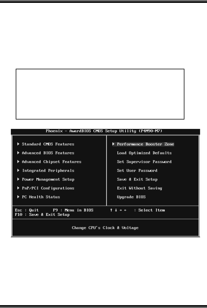
P4M900 Micro 775
3
1 Main Menu
Once you enter Award BIOS™ CMOS Setup Utility, the Main Menu will
appear on the screen. The Main Menu allows you to select from several setup
functions. Use the arrow keys to select among the items and press <Enter> to
accept and enter the sub-menu.
Figure 1: Main Menu
Standard CMOS Features
This submenu contains industry standard configurable options.
Advanced BIOS Features
This submenu allows you to configure advanced features of the BIOS.
!! WARNING !
!
For better system performance, the BIOS firmware is being
continuously updated. The BIOS information described in
this manual (Fi g u re 1, 2, 3, 4, 5, 6, 7, 8, 9) is for your
reference only. The actual BIOS information and settings on
board may be slightly different from this manual.
P4M900 Micro 775
4
Advanced Chipset Features
This submenu allows you to configure special chipset features.
Integrated Peripherals
This submenu allows you to configure cert ain IDE hard drive options and
Programmed Input/ Output features.
Power Management Setup
This submenu allows you to configure the power managem ent features.
PnP/PCI Configurations
This submenu allows you to configure cert ain “ Plug and Play” and PCI options.
PC Health Status
This submenu allows you to monitor the hardware of your system.
Performance Booster Zone
This submenu allows you to change CPU Vcore Voltage and CPU/PCI clock.
(However, we suggest you to use the default setting. Changing the voltage and
clock improperly may damage the CPU or M/B!)
Load Optimized Defaults
This selection allows you to reload the BIOS when problem occurs during
system booting sequence. These configurations are factory settings optimized
for this system. A confirmation message will be displayed before defaults are
set.
P4M900 Micro 775
5
Set Supervisor Password
Setting the supervisor password will prohibit everyone except the supervisor
from making changes using the CMOS Setup Utility. You will be prompted with
to enter a password.
Set User Password
If the Supervisor Password is not set, then the User Password will function in
the same way as the Supervisor Password. If the Supervisor Password is set and
the User Password is set, the “User” will only be able to view configurations but
will not be able to change them.
Save & Exit Setup
Save all configuration changes to CMOS (memory) and exit setup. Confirmation
message will be displayed before proceeding.
Exit Without Sa ving
Abandon all changes made during the current session and exit setup.
Confirmation message will be displayed before proceeding.

P4M900 Micro 775
6
Upgrade BIOS
This submenu allows you to upgrade bios.
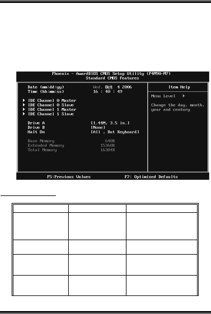
P4M900 Micro 775
7
2 Standard CMOS Features
The items in Standard CMOS Setup Menu are divided into several categories.
Each category includes no, one or more than one setup items. Use the arrow
keys to highlight the item and then use the<PgUp> or <PgDn> keys to select the
value you want in each item.
Figure 2: Standard CMOS Setup
Main Menu Selections
This table shows the items and the available options on the Main Menu.
Item Options Description
Date mm : dd : yy
Set the system date. Note
that the ‘Day ’ automatically
changes when you set the
date.
Time hh : mm : ss Set the system internal
clock.
IDE Channel 0 Master Options are in its sub
menu.
Press <Enter> to enter the
sub menu of detailed
options
IDE Channel 0 Slav e Options are in its sub
menu.
Press <Enter> to enter the
sub menu of detailed
options.

P4M900 Micro 775
8
Item Options Description
IDE Channel 1 Master Options are in its sub
menu.
Press <Enter> to enter the
sub menu of detailed
options.
IDE Channel 1 Slav e Options are in its sub
menu.
Press <Enter> to enter the
sub menu of detailed
options.
Driv e A
Driv e B
360K, 5.25 in
1.2M, 5.25 in
720K, 3.5 in
1.44M, 3.5 in
2.88M, 3.5 in
None
Select the ty pe of f loppy
disk drive installed in your
sy stem.
Halt On
All Errors
No Errors
All, but Key board
All, but Diskette
All, but Disk/ Key
Select the situation in which
y ou want the BIOS to stop
the POST process and
notify y ou.
Base Memory N/A
Displays the amount of
conv entional memory
detected during boot up.
Extended Memory N/A
Displays the amount of
extended memory detected
during boot up.
Tot al Mem ory N/ A Displays the total memory
av ailable in the system.
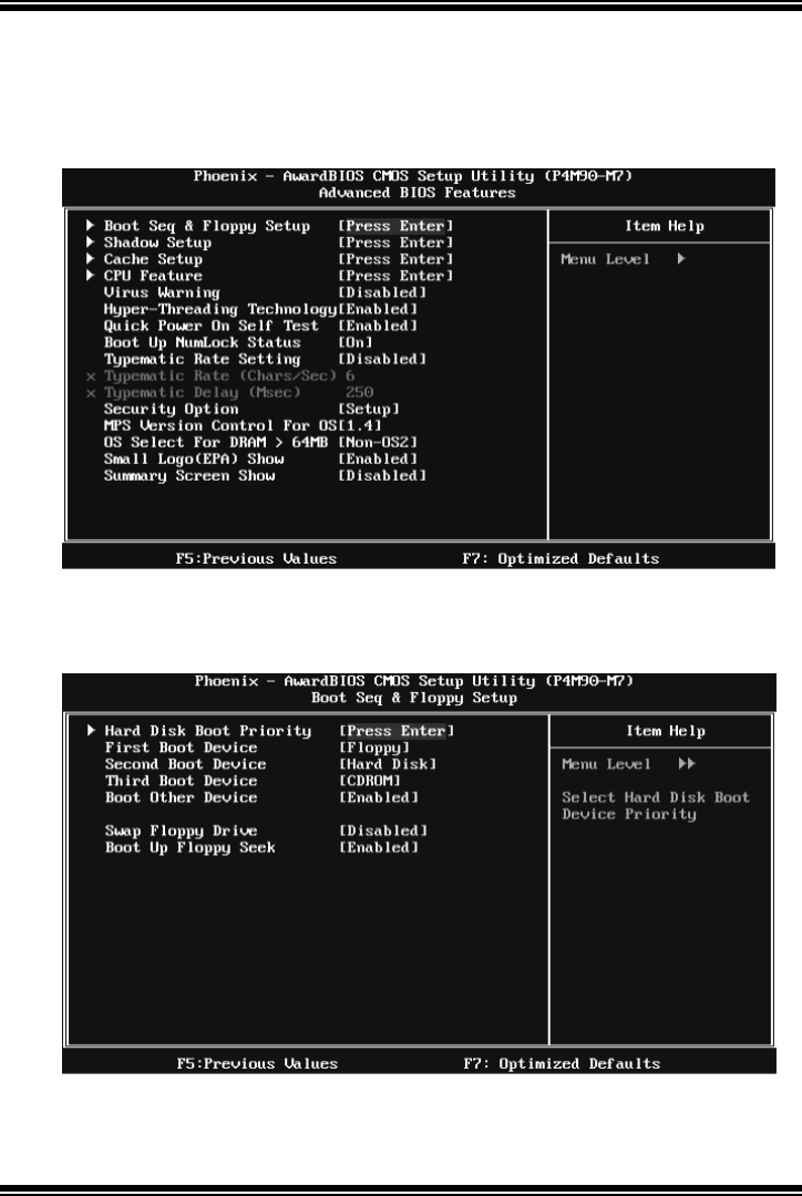
P4M900 Micro 775
9
3Advanced BIOS Features
Figure 3: Advanced BIOS Setup
Boot Seq & Floppy Setup
This item allows you to setup boot sequence & Floppy.
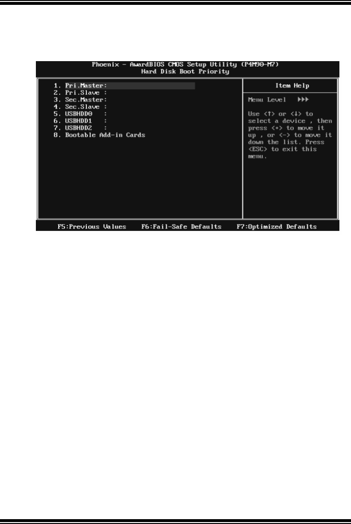
P4M900 Micro 775
10
Hard Disk Boot Priorit y
The BIOS will attempt to arrange the Hard Disk boot sequence automatically.
You can change the Hard Disk booting sequence here.
The Choices: Pri. Master, Pri. Slave, Sec. Master, Sec. Slave, USB HDD0, USB
HDD1, USB HDD2, and Bootable Add-in Cards.
First/Second/Third Boot Dev ice
The BIOS will attempt to load the operating system in this order.
The Choices: Floppy, LS120, Hard Disk, CDROM, ZIP100, USB-FDD,
USB-ZIP , USB-CDROM, LAN, Disabled.
Boot Other Dev ice
When enabled, BIOS will try to load the operating system from other device
when it failed to load from the three devices above.
The Choices: Enabled (default), Disabled
Sw ap Floppy Drive
For systems with two floppy drives, this option allows you to swap logical
drive assignments.
The Choices: Disabled (default), Enabled.
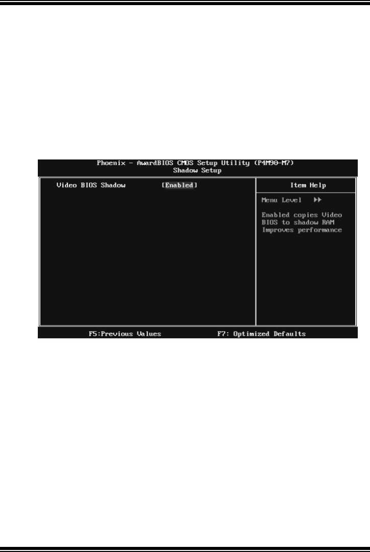
P4M900 Micro 775
11
Boot Up Floppy Seek
When enabled, System will test the floppy drives to determine if they have 40
or 80 tracks during boot up. Disabling this option reduces the time it takes to
boot-up.
The Choices: Enabled (default), Disabled.
Shadow Setup
This item allows you to setup cache & shadow setup.
Figure 3.2: Shadow Setup
Video BIOS Shadow
Determines whether video BIOS will be copied to RAM for faster execution or
not.
Enabled (default) Optional ROM is enabled.
Di sabled Opti on al ROM i s d i sabl ed .
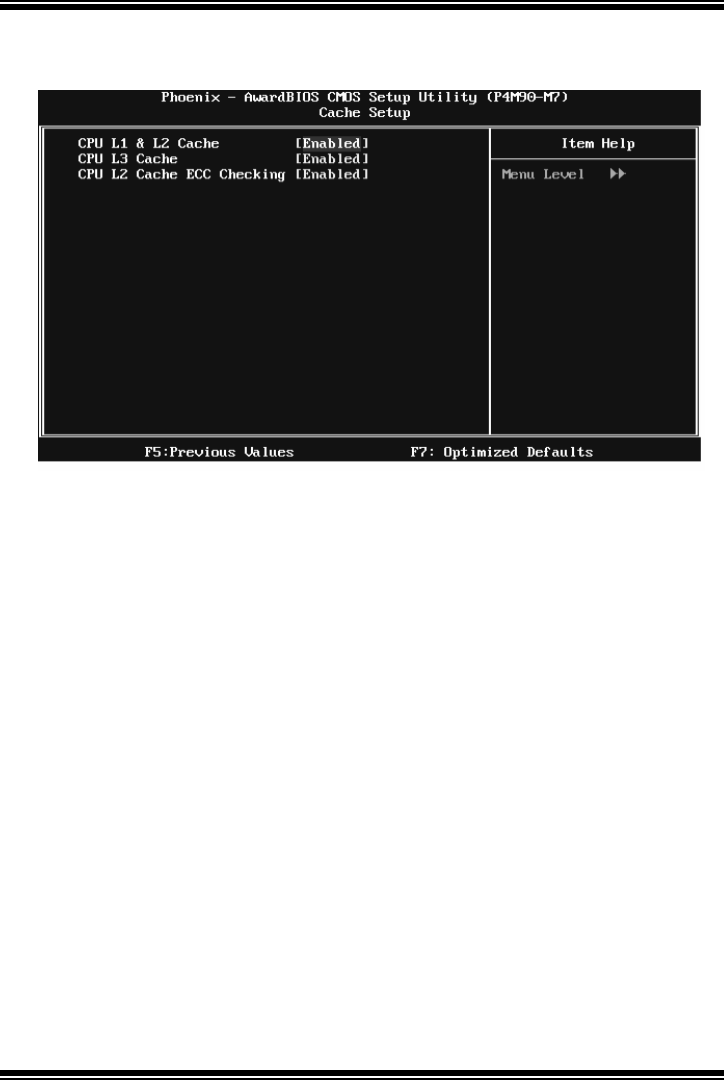
P4M900 Micro 775
12
Cache Setup
CPU L1 & L2 Cache
Depending on the CPU/chipset in use, you may be able to increase memory
access time with this option.
Enabled (default) Enable cache.
Disabled Disable cache.
CPU L3 Cache
Depending on the CPU/chipset in use, you may be able to increase memory
access time with this option.
Enabled (default) Enable cache.
Disabled Disable cache.
CPU L2 Cache ECC Checking
This item allows you to enable/disable CPU L2 Cache ECC Checking.
The Choices: Enabled (default), Disabled.
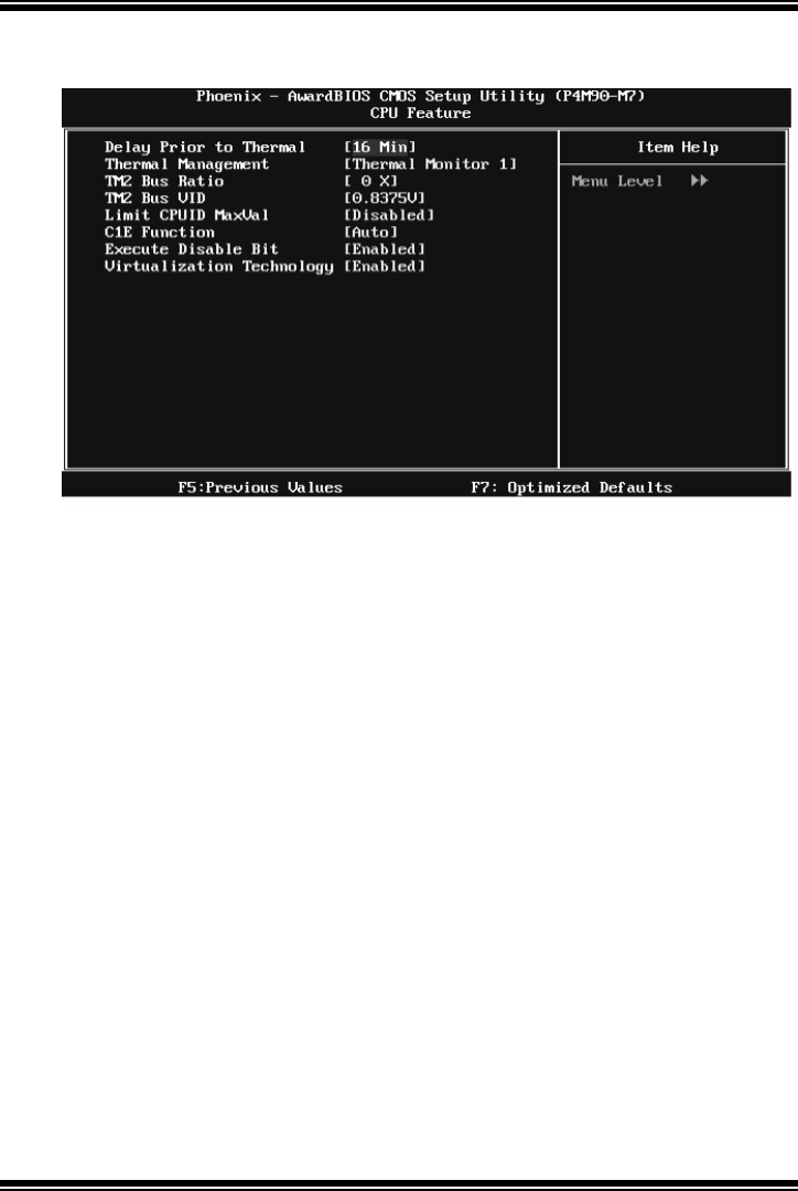
P4M900 Micro 775
13
CPU Feature
Delay Prior to Thermal
Set this item to enable the CPU Thermal function to engage after the specified
time.
The Choices: 4 Min, 8 Min, 16 Mi n (default), 32 Min.
The r m a l M a na ge me nt
Thi s op ti on al lo ws you to s el ect the w ay to cont rol th e “ Thermal Man agemen t .”
The Choices: Thermal Monitor 1 (default), Thermal Monitor 2.
TM2 Bus Ratio
This option represents the frequency (bus ratio) of the throttled performance
state that will be initiated when the on-die sensor detects temperature increase.
Min= 0 Max= 255 Key in a DEC number.
The Choices: 0 X (default)
TM2 Bus VID
This option represents the voltage of the throttled performance state that will be
initiated when the on-die sensor detects temperature increase.
The Choices: 0.8375V (d efau lt ), 0.83 75-1 .6 00 0 .

P4M900 Micro 775
14
Limit CPUID MaxVal
Set Limit CPUID MaxVal to 3, it should be “Disabled” for Windows XP.
The Choices: Disabled (default), Enabled.
C1E Function
This item allows you to configure the Enhanced Halt State (C1E) function,
which may reduce the power consumption of your system when the system is
idle.
The Choices: Auto (default),Disabled.
Exec ute Disable Bit
This item allows you to configure the Execute Disabled Bit function, which
protects your system from buffer overflow attacks.
The Choices: Enabled (default), Disabled.
Virtualization Technology
Virtualization Technology can virtually separate your system resource into
several parts, thus enhance the performance when running virtual machines or
multi interface systems.
The Choices: Enabled (default), Disabled.
Virus Warning
This option allows you to choose the VIRUS Warning feature th at is used to
protect the IDE Hard Disk boot sector. If this function is enabled and an attempt
is made to write to the boot sector, BIOS will display a warning message on the
screen and sound an alarm beep.
Disabled (default) Virus protection is disabled.
Enabled Virus protection is activated.
Hyper-Threading Technology
This option allows you to enable or disabled Hyper-Threading Technology.
“ Enabled” for Windows XP and Linux 2.4.x (OS optimized for
Hyper-Threading Technology). “ Disable” for other OS (OS not optimized for
Hyper-Threading Technology).
The Choices: En abled (default), Disabled.

P4M900 Micro 775
15
Quick Power On Self Test
Enabling this option will cause an abridged version of the Power On Self-Test
(POST) to execute after you power up the computer.
Disabled Normal POST.
Enabled (default) Enable quick POST .
Boot Up NumLock Status
Selects the NumLock State after the system switched on.
T he Choices:
On (default) Numpad is number keys.
Off Numpad is arrow keys.
Typematic Rate Setting
When a key is held down, the keystroke will repeat at a rate determined by the
keyboard controller. When enabled, the typematic rate and typematic delay can
be configured.
The Choices: Disabled (default), Enabled.
Typematic Rate (Chars/Sec)
Sets the rate at which a keystroke is repeated when you hold the key down.
The Choices: 6 (default), 8, 10, 12, 15, 20, 24, 30.
Typematic Delay (Msec)
Sets the delay time after the key is held down before it begins to repeat the
keystroke.
The Choices: 250 (default), 500, 750, 1000.
Security Option
This option will enable only individuals with passwords to bring the system
online and/or to use the CMOS Setup Utility.
System: A password is required for the system to boot and is also
required to access the Setup Utility.
Setup (default): A password is required to access the Setup Utility only.
This will only apply if passwords are set from the Setup main menu.

P4M900 Micro 775
16
MPS Version Control For OS
The BIOS supports version 1.1 and 1.4 of the Intel multiprocessor speci fication.
Select version supported by the operation system running on this computer.
The Choices: 1.4 (default), 1.1.
OS Select For DRAM > 64MB
A choice other than Non-OS2 is only used for OS2 systems with memory
exceeding 64MB.
The Choices: Non-OS2 (default), OS2.
Small Logo( EPA) Show
This item allows you to select whether the “Small Logo” shows. Enabled
(default) “ Small Logo” shows when system boots up. Disabled No “Small
Logo” shows when system boots
The Choices: En abled (default), Disabled
Summary Screen Show
This item allows you to enable/disable the summary screen. Summary screen
means system configuration and PCI device listing.
The Choices: Disabled (default), Enabled.
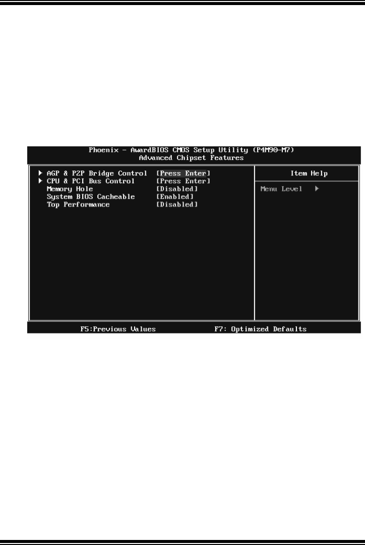
P4M900 Micro 775
17
4 Advanced Chipset Features
T his submenu allows you to configure the speci fic fe atures o f the chipset
installed on your system. This chipset manage bus speeds and access to system
memory resources, such as DRAM. It also coordinates communications with the
PCI bus. The default settings that came with your system have been optimized
and therefore should not be changed unless you are suspicious that the settings
have been changed incorrectly.
Figure 4: Advanced Chipset Setup
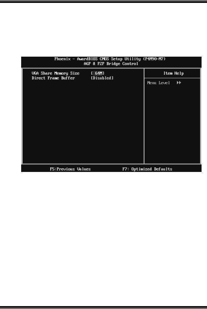
P4M900 Micro 775
18
AGP & P2P Bridge Control
Highlight “Press Enter” next to the “ AGP & P2P Bridge Control” label and
pressing the enter key will take you a submenu with the following options:
Figure 4.1: AGP & P2P Bridge Control
VGA Share Memory Size
This item allows you to select the VGA share memory size.
The Choices: 64M (default), 128M, 256M, 512M, Disabled
Direct Frame Buffer
This item allows you to disabled or enabled direct frame buffer
The Choices: Disabled (default), Enabled.
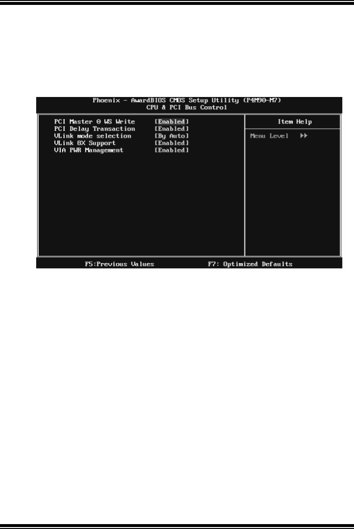
P4M900 Micro 775
19
CPU & PCI Bus Contro l
By highlighting the “Press Enter” label next to the “CPU & PCI Bus Control”
and press the enter key, it will take you a submenu with the following options:
Figure 4.2: CPU & PCI Bus Control
PCI Master 0 WS Write
When enabled, writes to the PCI bus are executed with zero-wait states.
The Choices: Enabled (default), Disabled.
PCI Delay Transaction
The chipset has an embedded 32-bit posted write buffer to support delay
transactions cycles. Select Enabled to support compliance with PCI
specification.
The Choices: Enabled (default), Disabled.
Vlink mode selection
This item allows you to select Vlink mode.
The Choices: By Auto (default), Mode 0 , Mode 1, Mode 2, Mode 3, Mode 4.

P4M900 Micro 775
20
VLink 8X Support
This item allows you to enable or disable VLink 8X support.
The Choices: Enabled (default), Disabled.
VIA PWR Management
The Choices: Enabled (default), Disabled.
Memory Hole
You can reserv e this area of system memory for ISA adapter ROM. When this
area is reserved it cannot be cached. Check the user information of periph erals
that need to use this area of system memory for the memory requirements.
The Choices: Disabled (default), Enabled.
System BIOS Cacheable
Selecting the “ Enabled” option allows caching of the system BIOS ROM at
F0000h-FFFFFh, which is able to improve the system performance. However,
any programs that attempts to write to this memory block will cause conflicts
and result in system errors.
The Choices: En abled (default), Disabled.
Top Performance
The Choices: Disabled (default), Enabled.
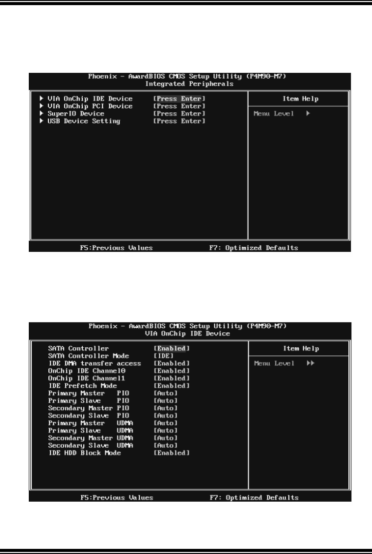
P4M900 Micro 775
21
5 Integrated Peripherals
Figure 5. Integrated Perip herals
VIA OnChip IDE Device
Highlight the “Press Enter” label next to the “ VIA OnChip IDE Device” label
and press enter key will take you a submenu with the following options:

P4M900 Micro 775
22
SATA Controller
Thi s op ti on al lo ws you to en ab l e th e on-chi p Serial ATA .
The Choices: Enabled (default), Disabled.
SATA Controller Mode
Thi s op ti on al lo ws you to s el ect SA TA Mo d e.
The Choices: RAID, IDE (default).
IDE DMA Transfer Access
This item allows you to enable or disable the IDE DMA transfer access.
The Choices: Enabled (default), Disabled.
On-chip IDE Channel 0/1
The motherboard chipset contains a P CI IDE interface with support for two
IDE channels. Select “ Enabled” to activate the first and/or second IDE interface.
Select “ Disabled” to deactivate an interface if you are going to install a primary
and/or secondary add-in IDE interface.
The Choices: Enabled (default), Disabled.
IDE Prefetch Mode
The “ onboard” IDE drive interfaces supports IDE prefetch function for faster
drive access. If the interface on your drive does not support prefetching, or if
you install a primary and/or secondary add-in IDE interface, set this option to
“Disabled”.
The Choices: Enabled (default), Disabled.
Primary/Secondary/Master/Slave PIO
The IDE PIO (Programmed Input / Output) fields let you set a PIO mode (0-4)
for each of the IDE devices that the onboard IDE interface supports. Modes 0
to 4 will increase performance progressively. In Auto mode, the system
automatically determines the best mode for each device.
The Choices: Auto (default), Mode0, Mode1, Mode2, Mode3, Mode4.

P4M900 Micro 775
23
Primary/Secondary/Master/Slave UDMA
Ultra DMA function can be implemented if it is supported by the IDE hard
drives in your system. As well, your operating environment requires a DMA
driver (Windows 95 or OSR2may need a third party IDE bus master driver). If
your hard drive and your system software both support Ultra DMA, select Auto
to enable BIOS support.
The Choices: Auto (default), Disabled.
IDE HDD Block Mode
Block mode is also called block transfer, multiple commands, or multiple
sectors read / write. If your IDE hard drive supports block mode (most new
drives do), select Enabled for automatic detection of the optimal number of
block mode (most new drives do), select Enabled for automatic detection of the
optimal number of block read / write per sector where the drive can support.
The Choices: Enabled (default), Disabled.
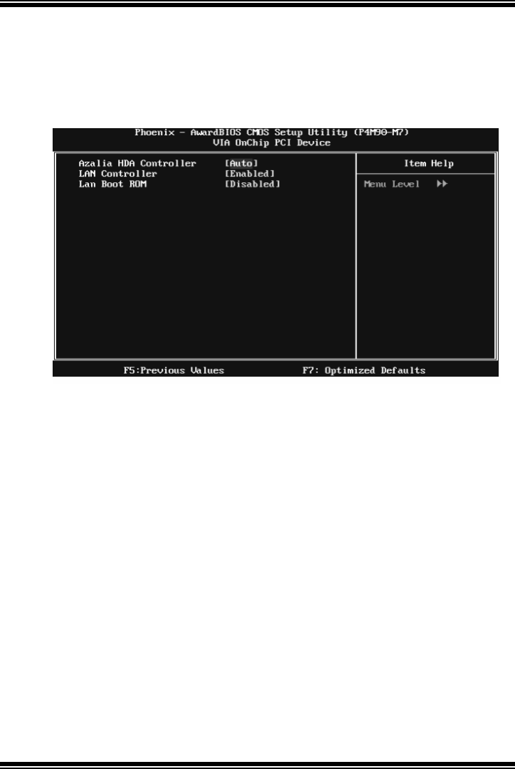
P4M900 Micro 775
24
VIA OnChip PCI Device
Highlight the “Press Enter” label next to the “ VIA OnChip PCI Device” label
and press the enter key will take you a submenu with the following options:
Figure 5.2: VIA OnChip PCI Device
Azalia HDA Controller
Thi s op ti on al lo ws you to con t ro l th e on bo ard H D aud io .
The Choices: Auto (default), Disabled.
LAN Controller
Thi s op ti on al lo ws you to con t ro l th e on bo ard L AN .
The Choices: Enabled (default), Disabled
Lan Boot ROM
Decide whether to invoke the boot ROM of the onboard LAN chip.
The Choices: Disable (default), Enabled.
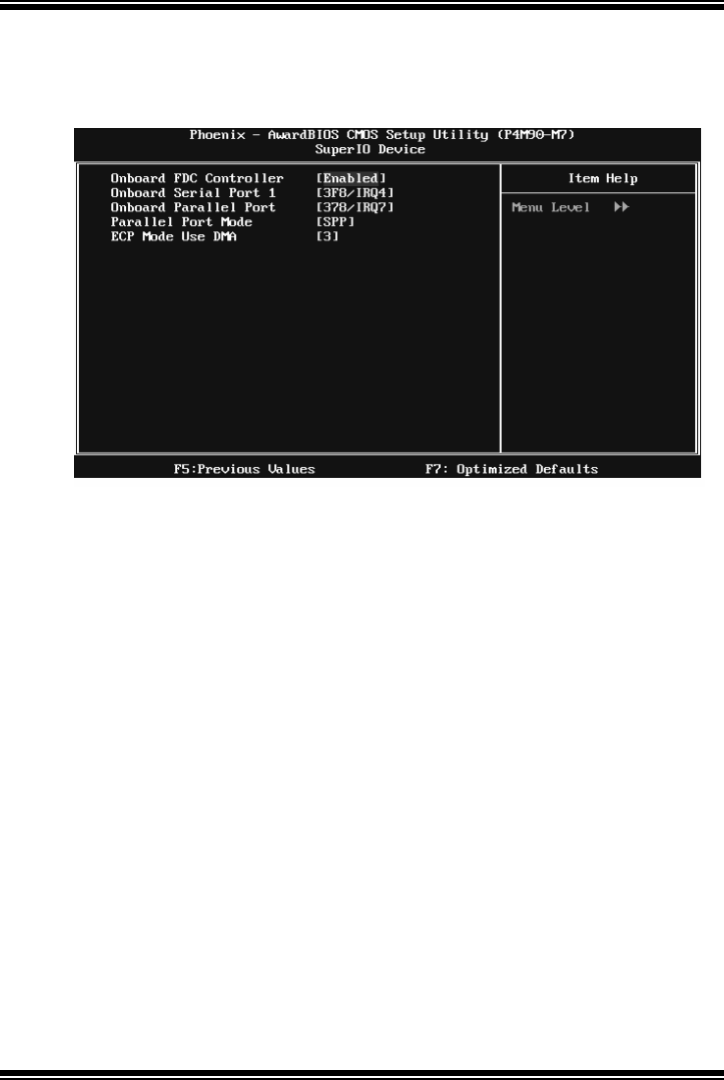
P4M900 Micro 775
25
Super IO Device
Press Enter to configure the Super I/O Device.
Onboard FDC Controller
Select enabled if your system has a floppy disk controller (FDC) installed on
the system board and you wish to use it. If you installed another FDC or the
system uses no floppy drive, select disabled in this field.
The Choices: Enabled (default), Disabled.
Onboard Serial Port 1
Select an address and corresponding interrupt for the first and second serial
ports.
The Choices: 3F8/IRQ4 (default), Disabled, 2F8/IRQ3, 3E8/IRQ4, 2E8/IRQ3,
Auto.
Onboard Parallel Port
This item allows you to determine access onboard parallel port controller with
which I/O Address.
The Choices: 378/IRQ7 (default), 278/IRQ5, 3BC/IRQ7, Disabled.
Parallel Port Mode
This item allows you to determine how the parallel port should function. The
default value is SPP.

P4M900 Micro 775
26
The Choices:
SPP (de fault) Using P arallel port as Standard Printer Port.
EPP Using Parallel Port as Enhanced Parallel Port.
ECP Using Parallel port as Extended Capabilities Port.
ECP+EPP Using Parallel port as ECP & EPP mode.
ECP Mode Use DMA
Select a DMA Channel for the port.
The Choices: 3 (default), 1.

P4M900 Micro 775
27
USB De vice Setting
Press Enter to configure the USB Device.
USB 1.0/2.0 Controller
These options allow you to enable or disable the USB 1.0/2.0 controller
function.
The Choices: Enabled (default), Disabled.
USB Operation Mode
This option let you select the operation mode of USB function.
The Choices: High Speed (default), Full/Low Speed.
USB Keyboard/Mouse/Storage Function
These options allow you to enable or disable the USB keyboard/mouse/storage
devices.
The Choices: Enabled (default), Disabled.
USB Mass Storage Dev ice Boot Setting
These options allow you to choose the boot up type of the USB mass storage
devices..
The Choices: Auto mode (default), FDD mode, HDD mode.
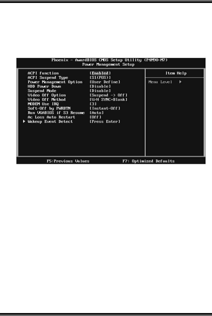
P4M900 Micro 775
28
6 Power Management Setup
The Power Management Setup Menu allows you to configure you r system to
utilize energy conservation and power up/power down features.
Figure 6. Power Management Setup
ACPI Function
This item displays the status of the Advanced Configuration and Power
Management (ACPI).
The Choices: En abled (default), Disabled.
ACPI Suspend Type
The item allows you to select the suspend type under the ACPI operating
system.
The Choices: S1 (POS) (default) Power on Suspend
S3 (ST R) Suspend to RAM
S1 & S3 POS+STR

P4M900 Micro 775
29
Power Management
This category allows you to select the power saving method and is directly
related to the following modes:
1. HDD Power Down.
2. Suspend Mode.
There are three options of Power Management, three of which have fixed mode
settings
Min. Power Saving
Minimum power management.
Suspend Mode = 1 hr.
HDD Power Down = 15 min
Max. Power Saving
Maximum power management only available fo r sl CPU’s.
Suspend Mode = 1 min.
HDD Power Down = 1 min.
User Define (default)
Allow you to set each option individually.
When you choose user define, you can adjust each of the item from 1 min. to 1
hr. except fo r HDD Power Down which ranges from 1 min. to 15 min.
HDD P ow er Down
When enabled, the hard-disk drives will power down after a set time of system
inactivity. All other devices remain active.
The Choices: Disabled (default), 1 Min, 2 Min, 3 Min, 4 Min, 5 Min, 6 Min, 7
Min, 8 Min, 9 Min, 10 Min, 11 Min, 12 Min, 13 Min, 14 Min, 15Min.
Suspend Mode
The item allows you to adjust the system idle time before suspend.
The Choices: Disabled (defau l t ), 1 Mi n, 2 Mi n, 4 Mi n, 6 M i n, 8 M i n , 10 M i n,
20 Min, 30 Min, 40 Min, 1 Hour.
Video Off Option
T his field determines when to activate the video off feature for monitor power
management.
The Choices: Suspend→Off (default), Always on.

P4M900 Micro 775
30
Video Off Method
This option determines the manner when the monitor goes blank.
V/H SYNC+Blank (default)
This selection will cause the system to turn off the vertical and horizontal
synchronization ports and write blanks to the video buffer.
Blank Screen
This option only writes blanks to the video buffer.
DPMS
Initial display power management signaling.
Modem Use IRQ
This determines the IRQ, which can be applied in MODEM use.
The Choices: 3 (default), 4, 5, 7, 9, 10, 11, NA.
Soft-Off by PWRBTN
This item determines the behavior of system power button. Instant off turn o ff
the power immediately, and Delay 4 Sec. will require you to press and hold the
power button for 4 seconds to cut off the system power.
The Choices: Delay 4 Sec, Instant-Off (default).
Run VGABIOS if S3 Resume
Choosing Enabled will make BIOS run VGA BIOS to initialize the VGA card
when system wakes up from S3 state. The system resume time is shortened if
you disable the function, but system will need AGP driver to initialize the card.
So, if the AGP driver of the VGA card does not support the initialization feature,
the display may work abnormally or not function after S3.
The Choices: Au to (default), Yes, No.
Ac Loss Auto Restart
This setting specifies how your system should behave aft er a power fail or
interrupts occurs. By choosing off will leave the computer in the power off state.
Choosing On will reboot the computer. Former-Sts will restore the system to the
status before power failure or interrupt occurs.
The Choices: Of f (default), On, Former-Sts.
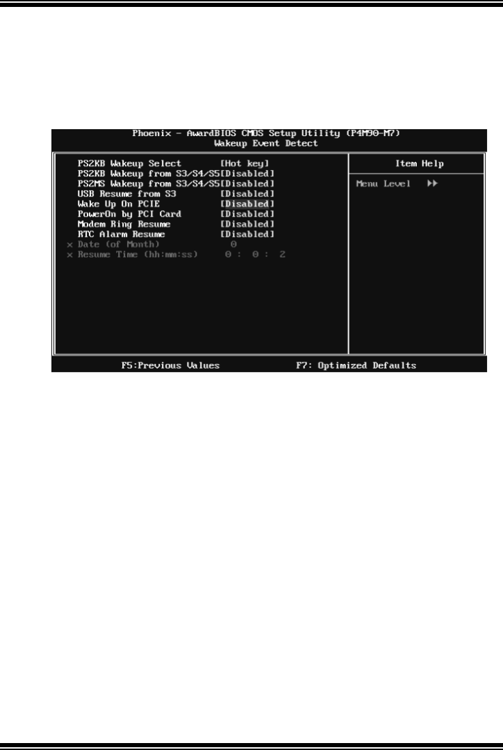
P4M900 Micro 775
31
Wakeup Event Detect
Figure 6.1:IRQ/Event Activity Detect
Highlight the “Press Enter” label next to the “ IRQ/Event Activity Detect” label
and press the enter key will take you a submenu with the following options:
PS2KB Wakeup Select
When select Password, please press Enter key to change password with a
maxi mum length of 8 characters.
The Choices: Hot Key (default), P assword.
PS2KB Wakeup from S3/ S4/ S5
This item allows you to wake up from S3/ S4/ S5 with PS2 keyboard.
The Choices: Disabled (default), Ctrl+F1, Ctrl+F2. Ctrl+F3, Ctrl+F4, Ctrl+F5,
Ctrl+F6, Ctrl+F7, Ctrl+F8, Ctrl+F9, Ctrl+F10, Ctrl+F11, Ctrl+F12, Power,
Wake, Any Key.
PS2MS Wakeup from S3/ S4/ S5
This item allows you to wake up from S3/ S4/ S5 with PS2 mouse.
The Choices: Disabled (default), Enabled.
USB Resume from S3
This item allows you to wake up from S3 with USB device.

P4M900 Micro 775
32
The Choices: Disabled (default), Enabled.
Wake Up On PCIE
When set to Enabled, PCI-Express device will be able to wake up the system.
For this function to work, you may need a LAN add-on card which supports the
Wake on LAN function. Set the Wake on LAN (WOL) jumper on motherboard
to enable if applicable.
The Choices: Disabled (default), Enabled.
PowerOn by PCI Card
When you select Enabled, a PME signal from P CI card returns the system to
Full ON state.
For this function to work, you may need a LAN add-on card which supports the
Wake on LAN function. Set the Wake on LAN (WOL) jumper on motherboard
to enable if applicable.
The Choices: Disabled (default), Enabled.
Modem Ring Resume
This item allows you to disable or enable Modem Ring Resume function.
The Choices: Disabled (default), Enabled.
RTC Alarm Resume
When “ Enabled”, you can set the date and time at which the RTC (real-time
clock) alarm awakens the system fro m Suspend mode.
The Choices: Disabled (default), Enabled.
Date (of M onth)
You can choose which month the system will boot up. This field is only
configurable when “RTC Resume” is set to “Enabled”.
Resume Time (hh:mm:ss)
You can choose the hour, minute and second the system will boot up. This field
is only configurable when “RTC Resume” is set to “Enabled”.
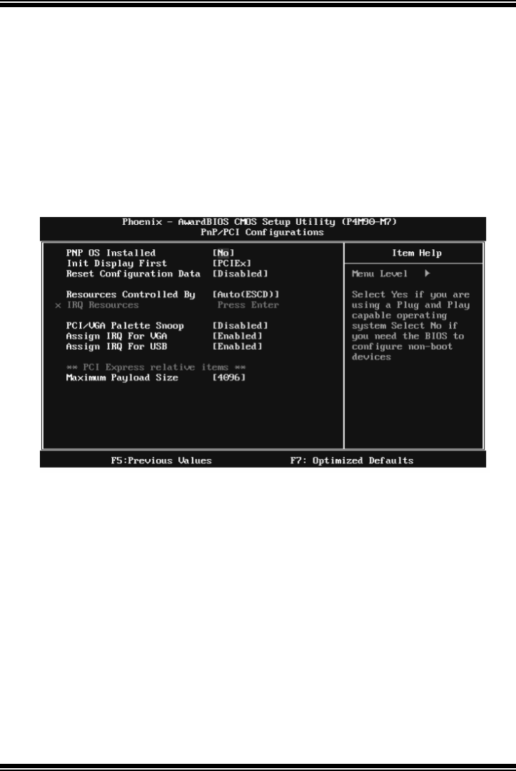
P4M900 Micro 775
33
7 PnP/PCI Configurations
This section describes configuring the PCI bus system. PCI, or Personal
Computer Interconnect, is a system which allows I/O devices to operate at
speeds nea ring the speed o f the CPU itself uses when communicating with its
own special components. This section covers some very technical items and it is
strongly recommended that only experienced users should make any changes to
the default settings.
Figure 7: PnP/PCI Configurations
PNP OS Installed
When set to YES, BIOS will only initialize the PnP cards used for the boot
sequence (VGA, IDE, SCSI). T he rest of the cards will be initialized by the PnP
operating system like Window™ 95. When set to NO, BIOS will initialize all
the PnP cards. For non-PnP operating systems (DOS, Netware™), this option
must set to NO.
The Choices: No (default), Yes.

P4M900 Micro 775
34
Init Display First
This item allows you to decide to active whether PCI Slot or on-chip VGA first.
The Choices: PCIEx (default), PCI Slot, Onboard, AGP.
Reset Configuration Data
The system BIOS supports the PnP feature which requires the system to record
which resources are assigned and protects resources from conflict.
Every peripheral device has a node, which is called ESCD. This node records
which resources are assigned to it. The system needs to record and update ESCD
to the memory locations. These locations are reserved in the system BIOS. If the
Disabled (default) option is chosen, the system‘s ESCD will update only when
the new configuration varies from the last one. If the Enabled option is chosen,
the system is forced to update ESCDs and then is automatically set to the
“ Disabled” mode.
The above settings will be shown on the screen only if “ Manual” is chosen for
the resources controlled by function.
Legacy is the term, which signifies that a resource is assigned to the ISA Bus
and provides non-PnP ISA add-on cards. PCI / ISA PnP signify that a resource
is assigned to the PCI Bus or provides for ISA PnP add-on cards and
peripherals.
The Choices: Disabled (default), Enabled.
Resources Controlled By
By Choosing “Auto(ESCD)” (default), the system BIOS will detect the system
resourc es and automatically assign the relative IRQ and DMA channel for each
peripheral. By Choosing “Manual”, the user will need to assign IRQ & DMA for
add-on cards. Be sure that there are no IRQ/DMA and I/O port conflicts.
The Choices: Auto (ESCD) (default), Manual.

P4M900 Micro 775
35
IRQ Resources
This submenu will allow you to assign each system interrupt a type, depending
on the type of device using the interrupt. When you press the “ Press Enter” tag,
you will be directed to a submenu that will allow you to configure the system
interrupts. This is only configurable when “ Resources Controlled By” is set to
“Manual”.
IRQ-3 assigned to PCI Device
IRQ-4 assigned to PCI Device
IRQ-5 assigned to PCI Device
IRQ-7 assigned to PCI Device
IRQ-9 assigned to PCI Device
IRQ-10 assigned to PCI Device
IRQ-11 assigned to PCI Device
IRQ-12 assigned to PCI Device
IRQ-14 assigned to PCI Device
IRQ-15 assigned to PCI Device
PCI / VGA Palette Snoop
Some old graphic controllers need to “ snoop” on the VGA palette and then map
it to their display as a way to provide boot in formation and VGA compatibility.
This item allows such snooping to take place.
The Choices: Disabled (default), Enabled
Assign IRQ For VGA
This item allows the users to choose which IRQ to assign for the VGA.
The Choices: En abled (default), Disabled.
Assign IRQ For US B
This item allows the users to choose which IRQ to assign for the USB.
The Choices: En abled (default), Disabled.
Maximum Payload Size
Set the maximum payload size for T ransaction packets (T LP).
The Choice: 4096 (default.), 128, 256, 512, 1024, 2048.
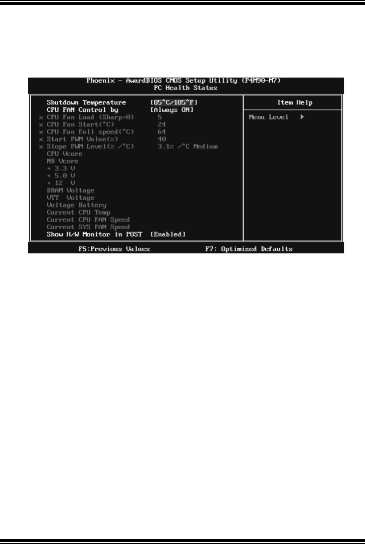
P4M900 Micro 775
36
8 PC Health Status
Figure 8: PC Health Status
Shutdown Temperature
This item allows you to set up the CPU shutdown Temperature. This item is
only effective under Windows 98 ACPI mode.
The Choices: 70℃/ 158℉, 75℃/ 167℉, 80℃/ 176℉, 85℃/ 185℉(default).
CPU FAN Control b y
Choose “ smart” to reduce the noise caused by CPU FAN.
The Choices: Smart, Always On (default).
CPU Fan Load (Sharp=0)
The Choices: Min=0, Max=7; key in a DEC number.
CPU Fan Start (℃)
CPU fan starts to work under smart fan function when arrive this set value.
The Choices: Min=0, Max=100; key in a DEC number.

P4M900 Micro 775
37
CPU Fan Full speed <℃>
When CPU temperature is reach the set value, the CPU fan will work under Full
Speed.
The Choices: Min=0, Max=100; key in a DEC number.
Start PWM Value (%)
When CPU temperature arrives to the set value, the CPU fan will work under
Smart Fan Function mode. The range is from 0~127, with an interval of 1.
The Choices: Min=0, Max=100; key in a DEC number.
Slope PWM Level ( %/℃)
Increasing the value of slope PWM will raise the speed of CPU fan.
The Choices: 3.1%/℃ Medium(default), 0.0%/℃, 0.8%/℃, 1.6%/℃,6.3%/℃
High,12.5%/℃, 25.0%/℃, 50.0%/℃.
CPU Vcore, NB Vcore, +3.3V, +5.0V, +12V, DRAM Voltage,
VTT Voltage, Voltage Battery
Detect the system’s voltage status automatically.
Current CP U Temp
T his field displays the current temperatur e o f CPU.
Current CP U FAN Speed
This field displays the current speed of CPU fan.
Current S YS FAN Speed
This field displays the current speed SYSTEM fan.
Show H/W Monitor in POST
If you computer contains a monitoring system, it will show PC health status
during POST stage. The item offers several different delay times.
The Choices: En abled (default), Disabled.
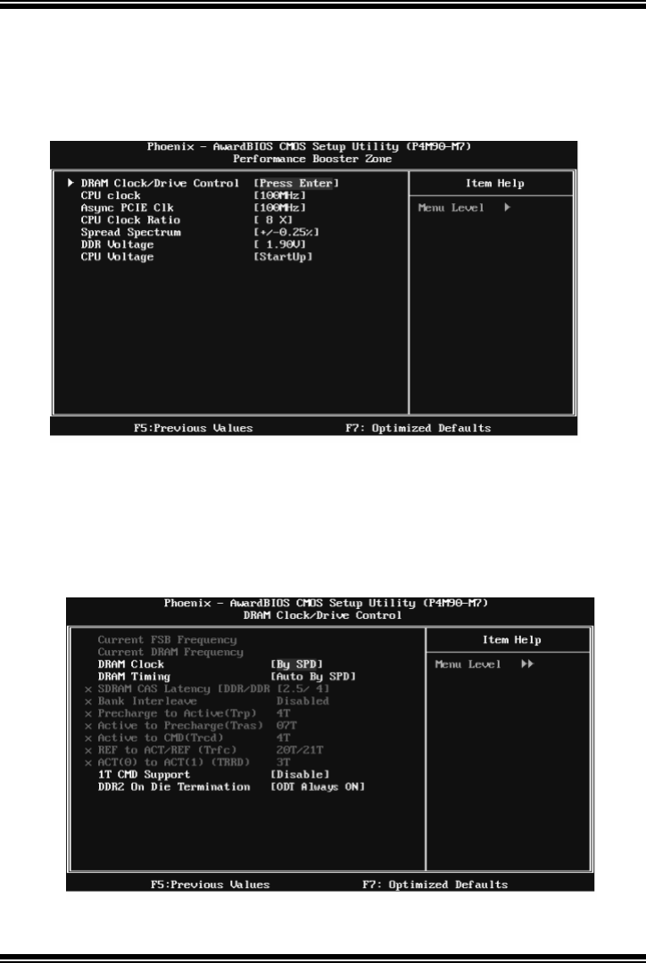
P4M900 Micro 775
38
9 Performance Booster Zone
Figure 9: Perf ormance Booster Zone
DRAM Clock/Dri ve Control
This item controls the DRAM Clock. Highlight “Press Enter” next to the
“ DRAM Clock/Drive Control” label and pressing the enter key will take you a
submenu with the following options:
Figure 9.1: DRAM Clock/Drive Control

P4M900 Micro 775
39
DRAM Clock
This item determines DRAM clock.
The Choices: By SPD (default), 100MHz, 133MHz, 166MHz, 200MHz,
266MHz, 333MHz .
DRAM Timing
This item determines DRAM clock/ timing.
The Choices: Auto by SPD (default), Manual, Turbo, Ultra.
SDRAM CAS Latency
When DRAM is installed, the number of clock cycles of CAS latency depends
on the DRAM timing.
The Choices: 2.5 /4(default).
Bank Interleave
This item allows you to enable or disable the bank interleave feature.
The Choices: Disabled (default).
Precharge to Active (tRP)
This item allows you to specify the delay from precharge command to activate
c o mma n d .
The Choices: 4T (default).
Activ e to Precharge (tRAS)
This item allows you to specify the minimum row active time (tRAS).
The Choices: 07T (default).
Activ e to CMD (tRCD)
Use this item to specify the delay from the activation of a bank to the time that
a read or write command is accepted.
The Choices: 4T (default).
REF to ACT/REF to REF (Trfc)
This item allows you to determine the selection for REF to ACT/REF to REF
(tRFC).
The Choices: 20T/21T (default).

P4M900 Micro 775
40
AC T (0) to ACT (1) ( tRRD)
This item allows you to determine the selection for ACT (0) to ACT (1) (tRRD)
The Choices: 3T (default).
1T CMD Support
The Choices: Disable (default), Auto.
DDR2 On Die Termination
Thi s op ti on al lo ws you to cho ose t he w o rki ng t yp e o f O D T.
The Choices: ODT Always ON (default), Dynamic ODT, ODT Always OFF.
CPU CLOCK
This item allows you to select CPU Clock, and CPU over clocking.
Special Notice:
If the system’s frequency that you are selected is not functioning, there are two
methods of booting-up the system.
Method 1:
Clear the COMS data by setting the JCOMS1 ((2-3) closed)) as “ ON” status. All
the CMOS data will be loaded as defaults setting.
Method 2:
Press the <Insert> key and Power button simultaneously, after that keep-on
pressing the <Insert> key until the power-on screen showed.
This action will boot-up the system according to FSB of the processor
It’s strongly recommended to set CPU Vcore and clock in default setting. If the
CPU Vcore and clock are not in default setting, it may cause CPU or M/B
damage.
The Choices: 100MHz(default); Min=100, Max=400, key in a DEC number.
Async P CIE CLOCK
This item allows you to select Async PCIE clock.
Min= 100 Max=150 Key in a DEC number.
The Choices: 100MHz(default) ; Min=100, Max=150, key in a DEC number.
CPU Clock Ratio
This item allows you to select the CPU Ratio.
Min= 6 Max= 50 Key in a DEC number.
The Choices: 6X (default).

P4M900 Micro 775
41
Spread Spectrum
This item allows you to enable/disable the Spread Spectrum function.
The Choices:+/- 0.25% (default), +/- 0. 5%, Disabled, -0.5%, -1.0%.
DDR Voltage
This item allows you to select DDR Voltage.
The Choices: StartUp (default), +0.10V, +0.20V, +0.30V, +0.40V, +0.50V,
+0.60V, +0.70V.
CPU Voltage
This item allows you to select CPU Voltage.
The Choices: StartUp (default), +0.012V~+0.787V.
