Biostar Tpower X58 Owners Manual IX58A AXP_IX58B AXP_090806
2014-07-31
: Biostar Biostar-Tpower-X58-Owners-Manual biostar-tpower-x58-owners-manual biostar pdf
Open the PDF directly: View PDF ![]() .
.
Page Count: 69

TPower X58/TPower X58A Setup Manual
FCC Information and Copyright
This equipment has been tested and found to comply with the limits of a Class
B digital device, pursuant to Part 15 of the FCC Rules. These limits are designed
to provide reasonable protection against harmful interference in a residential
installation. This equipment generates, uses, and can radiate radio frequency
energy and, if not installed and used in accordance with the instructions, may
cause harmful interference to radio communications. There is no guarantee
that interference will not occur in a particular installation.
The vendor makes no representations or warranties with respect to the
contents here and specially disclaims any implied warranties of merchantability
or fitness for any purpose. Further the vendor reserves the right to revise this
publication and to make changes to the contents here without obligation to
notify any party beforehand.
Duplication of this publication, in part or in whole, is not allowed without first
obtaining the vendor’s approval in writing.
The content of this user’s manual is subject to be changed without notice and
we will not be responsible for any mistakes found in this user’s manual. All the
brand and product names are trademarks of their respective companies.

Table of Contents
Chapter 1: Introduction ........................................ 1
1.1 Before You Start......................................................................................... 1
1.2 Package Checklist ..................................................................................... 1
1.3 Motherboard Features.............................................................................. 2
1.4 Rear Panel Connectors.............................................................................. 3
1.5 Motherboard Layout................................................................................. 4
Chapter 2: Hardware Installation .......................... 5
2.1 Installing Central Processing Unit (CPU) ............................................... 5
2.2 FAN Headers.............................................................................................. 7
2.3 Installing System Memory ........................................................................ 8
2.4 Connectors and Slots................................................................................ 10
Chapter 3: Headers & Jumpers Setup .................. 13
3.1 How to Setup Jumpers............................................................................. 13
3.2 Detail Settings.......................................................................................... 13
Chapter 4: RAID Functions .................................. 20
4.1 Operating System.................................................................................... 20
4.2 Raid Arrays............................................................................................... 20
4.3 How RAID Works..................................................................................... 20
Chapter 5: T-Power BIOS & Software .................. 24
5.1 T-Power BIOS ........................................................................................... 24
5.2 T-Power Software .................................................................................... 33
Chapter 6: Useful Help ........................................ 43
6.1 Driver Installation Note.......................................................................... 43
6.2 Extra Information.................................................................................... 44
6.3 AMI BIOS Beep Code............................................................................... 45
6.4 AMI BIOS Post Code................................................................................. 46
6.5 Troubleshooting....................................................................................... 48
Appendix: SPEC In Other Languages ................... 50
German.................................................................................................................. 50
French .................................................................................................................... 52
Italian..................................................................................................................... 54
Spanish ................................................................................................................... 56
Portuguese ............................................................................................................ 58
Polish...................................................................................................................... 60
Russian ................................................................................................................... 62
Arabic..................................................................................................................... 64
Japanese ................................................................................................................ 66

TPower X58/TPower X58A
1
CHAPTER 1: INTRODUCTION
1.1 BEFORE YOU START
Thank you for choosing our product. Before you start installing the
motherboard, please make sure you follow the instructions below:
Prepare a dry and stable working environment with
sufficient lighting.
Always disconnect the computer from power outlet
before operation.
Before you take the motherboard out from anti-static
bag, ground yourself properly by touching any safely
grounded appliance, or use grounded wrist strap to
remove the static charge.
Avoid touching the components on motherboard or the
rear side of the board unless necessary. Hold the board
on the edge, do not try to bend or flex the board.
Do not leave any unfastened small parts inside the
case after installation. Loose parts will cause short
circuits which may damage the equipment.
Keep the computer from dangerous area, such as heat
source, humid air and water.
1.2 PACKAGE CHECKLIST
HDD Cable X 1
Serial ATA Cable X 6 (optional)
Serial ATA Power Cable X 6 (optional)
Rear I/O Panel for ATX Case X 1
User’s Manual X 1
Fully Setup Driver CD X 1
FDD Cable X 1 (optional)
USB 2.0 Cable X1 (optional)
S/PDIF out Cable X 1 (optional)
Note: The package contents may be different due to area or your motherboard version.

Motherboard Manual
2
1.3 MOTHERBOARD FEATURES
SPEC
CPU SOCKET 1366
Intel Core i7 Extreme / Core i7 processor
Supports Execute Disable Bit / Enhanced Intel
SpeedStep® / Intel Architecture-64 / Extended
Memory 64 Technology / Virtualization Technology /
Hyp er Thread ing
QPI Support 6.4GT/s
Chipset Intel X58
Intel ICH10R
Super I/O
IT8720
Provides the most commonly used legacy
Super I/O functionality.
Low Pin Count Interface
Environment Control init iatives,
Hardware Monitor Controller
Fan Speed Controller
ITE's "S mart Guardian" funct ion
Main
Memory
DIMM Slots x 6
Each DIMM supports 512MB / 1GB / 2GB /
4GB DDR3
Max Memory Capicity 24GB
Dual & Tr ip le Chann el Mode DDR3 memory module
Supports DDR3 1866(OC) / 1600(OC) / 1333 / 1066 /
800
Registered DIMM and ECC DIMM is not supported
IDE JMB363 Ultra DMA 33 / 66 / 100 / 133 Bus Master Mode
supports PIO Mode 0~4
SATA II ICH10R
Data transfer rates up to 3 Gb/s.
SATA Version 2.0 s pecif icat ion co mpliant.
RAID 0 / 1 / 5 / 10 support
eSATA JMB363
Data transfer rates up to 3 Gb/s.
SATA Version 2.0 s pecif icat ion co mpliant.
Port-Multiplier/RAID 0,1 support
LAN Realtek RTL 8111C x2 (TPower X58)
Realtek RTL 8111C x1 (TPower X58A)
10 / 100 Mb/s / 1Gb/s auto negotiation
Half / Full duplex capability
Sound
Codec ALC888S 7.1 channels audio out
High Definition Audio
IEEE 1394 Ti tsb43ab22a (TPower X58)
PCI slot x2 Supports PCI expansion cards
PCI Express Gen2 x16 slot (x16) x2 Supports PCI-E Gen2 x16 expansion cards
PCI Express Gen2 x16 slot (x4) x1 Supports PCI-E Gen2 x16 expansion cards
Slots
PCI Express x1 slot x1 Supports PCI-E x1 expansion cards
Floppy Connector x1 Each connector supports 2 Floppy drives
IDE Connector x1 Each connector supports 2 IDE device
SATA Connector x6 Each connector supports 1 SATA devices
On Board
Connector
Front Panel Connector x1 Supports front panel facilities
TPower X58/TPower X58A
3
SPEC
Front Audio Connector x1 Supports front panel audio function
CD-in Connector x1 Supports CD audio-in function
S/PDIF out Connector x1 Supports digital audio out function
CPU Fan Header x1 CPU Fan power supply (with Smart Fan function)
System Fan Header x2 System Fan Power supply
Clear CMOS Header x1 Restore CMOS data to factory default
USB Connector x2 Each connector supports 2 front panel USB ports
IEEE 1394 Connector (TPower X58) x1 Connects to IEEE 1394 device
Power Connector (24pin) x1 Connects to Power supply
Power Connector (8pin) x1 Connects to Power supply
Power Connector (4pin) x1 Connects to Power supply
Back Panel
I/O
PS/2 Keyboard x1
LAN Port x2
USB Port x8
Audio Jack x6
eSATA Port x2
1394 Port (TPower X58) x1
Optical +coaxial S/PDIF Out x1
Connects to PS/2 Keyboard
Connect to RJ-45 ethernet cab le
Connect to USB devices
Provide Audio-In/Out and microphone connection
Connect to SATA devices
Connects to IEEE 1394 device
Provides digital audio out function
Board Size 244 (W) x 305 (L) mm ATX
OS Support
Windows XP / Vista 32 / Vista 64 Biostar reserves the right to add or remove support for
any OS with or without notice
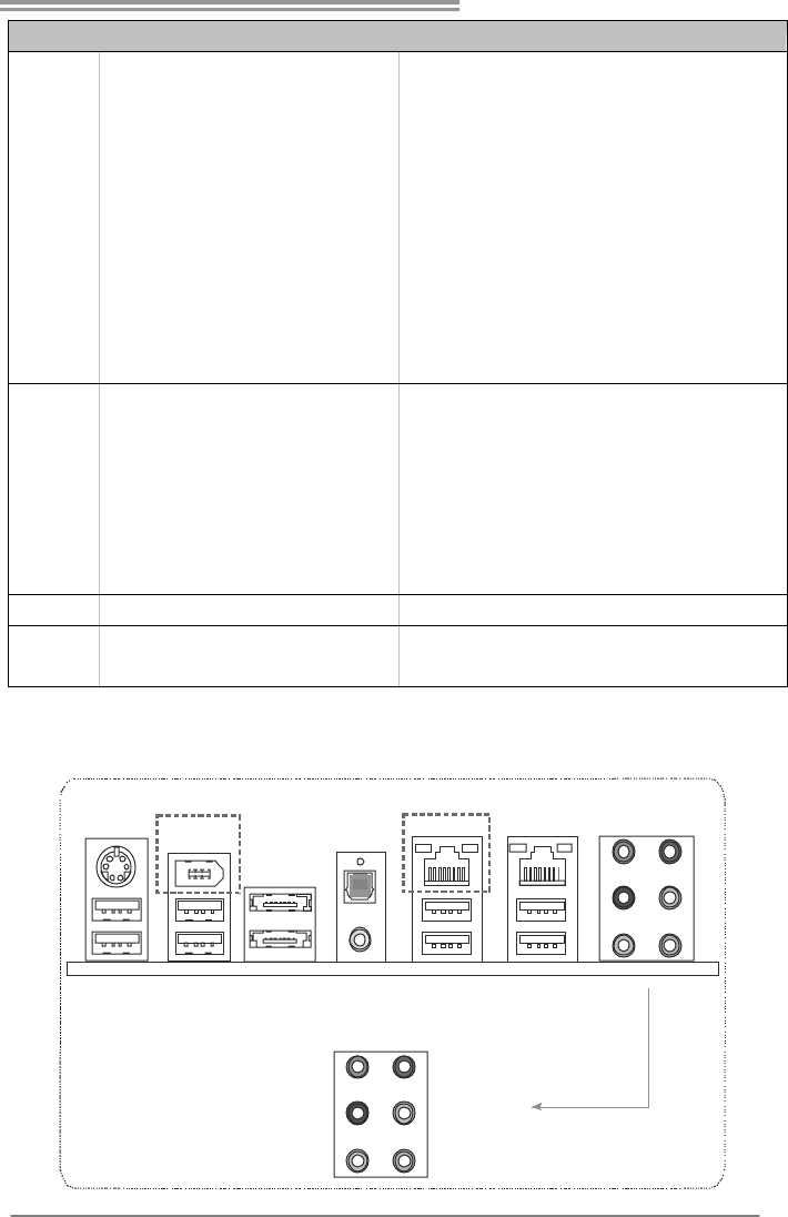
1.4 REAR PANEL CONNECTORS
Line In
Line Out
Mic In
Center
Rear
Side
PS/2
Keyboard
ESATAX2USBX2 USBX2
LAN
USBX2
IEEE 1394
USBX2
LAN
Optical
+coaxial
S/PDIF Out
(TPower X58) (TPower X58)
Motherboard Manual
4
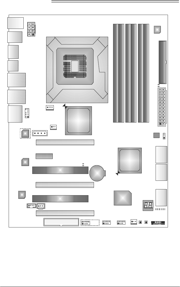
1.5 MOTHERBOARD LAYOUT
Socket 1366
CP U1
JUSBKB1
J1394_US1
ES ATAX1
JUSBLAN1
JUSBLAN2
JAUDI O1
JFSPDIF1
JATXPWR1
JCFAN1
JSFAN 1
JATXPWR3
PEX16_1
PEX16_2
PEX4_1
PCI1
PCI2
FDD1
JUSB2JUSB1
J1394_1
JSFAN2
RSTSW1
PWRSW1
JPANEL1
Super
I/O
IDE
IDE1
JAT XP WR2
SATA1
SATA2
SATA3
PEX1_1
BAT1
JC DIN 1 JSPD IF _ OU T1
BIOS
JCM O S1
DDR3_A1
DDR3_A2
DDR3_B1
DDR3_B2
DDR3_C1
DDR3_C2
Intel
X58
Intel
ICH10R
LAN
LAN
CODEC
JAUDI OF1
PH_LED 1
PH_LED 2
PH_LED 3
PH_LED 4
PH_LED 5
PH_LED 6
DDR_V_D2
DDR_V_D1
NB_V_ D1
NB_V_ D2
(TPower X58)
(TPower X58)
Note: represents the 1■st pin.
TPower X58/TPower X58A
5
CHAPTER 2: HARDWARE INSTALLATION
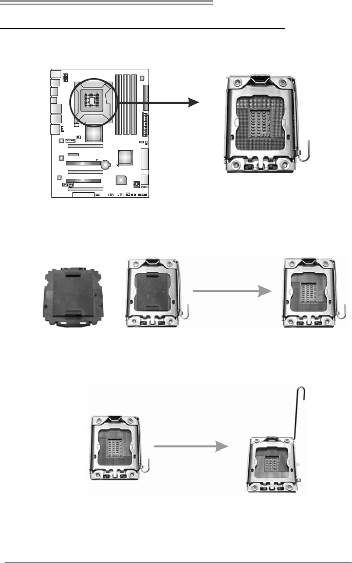
2.1 INSTALLING CENTRAL PROCESSING UNIT (CPU)
Special Notice:
Remove Pin Cap before installation, and make good preservation
for future use. When the CPU is removed, cover the Pin Cap on the
empty socket to ensure pin legs won’t be damaged.
Pin Cap
Step 1: Pull the socket locking lever out from the socket and then raise
the lever up to a 90-degree angle.
Motherboard Manual
6
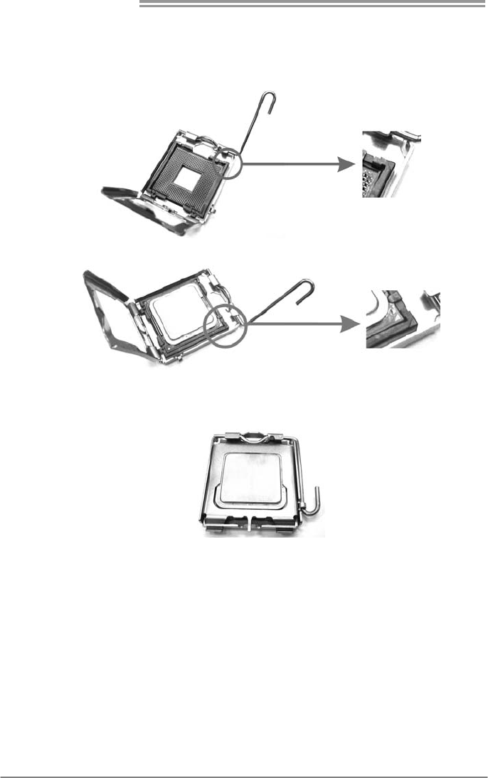
Step 2: Look for the triangular cut edge on socket, and the golden dot on
CPU should point forwards this triangular cut edge. The CPU will
fit only in the correct orientation.
Step 2-1:
Step 2-2:
Step 3: Hold the CPU down firmly, and then lower the lever to locked
position to complete the installation.
Step 4: Put the CPU Fan and heatsink assembly on the CPU and buckle it
on the retention frame. Connect the CPU FAN power cable into
the JCFAN1. This completes the installation.
TPower X58/TPower X58A
7
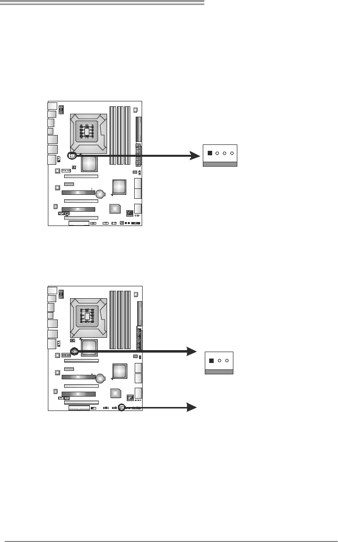
2.2 FAN HEADERS
These fan headers support cooling-fans built in the computer. The fan
cable and connector may be different according to the fan manufacturer.
Connect the fan cable to the connector while matching the black wire to
pin#1.
JCFAN1: CPU Fan Header
Pin
Assignment
1 Ground
2 +12V
3 FAN RPM rate
sense
14
4 Smart Fan
Control
JSFAN1: NorthBridge Fan Header
JSFAN2: System Fan Header
Pin
Assignment
1 Ground
2 +12V
13
JSFAN2
JSFAN1
3 FAN RPM rate
sense
Note:
The JSFAN1/JSFAN2 support 3-pin head connectors, and the JCFAN1, 4-pin head
connector. When connecting with wires onto connectors, please note that the red wire is
the positive and should be connected to pin#2, and the black wire is Ground and should
be connected to GND.
Motherboard Manual
8
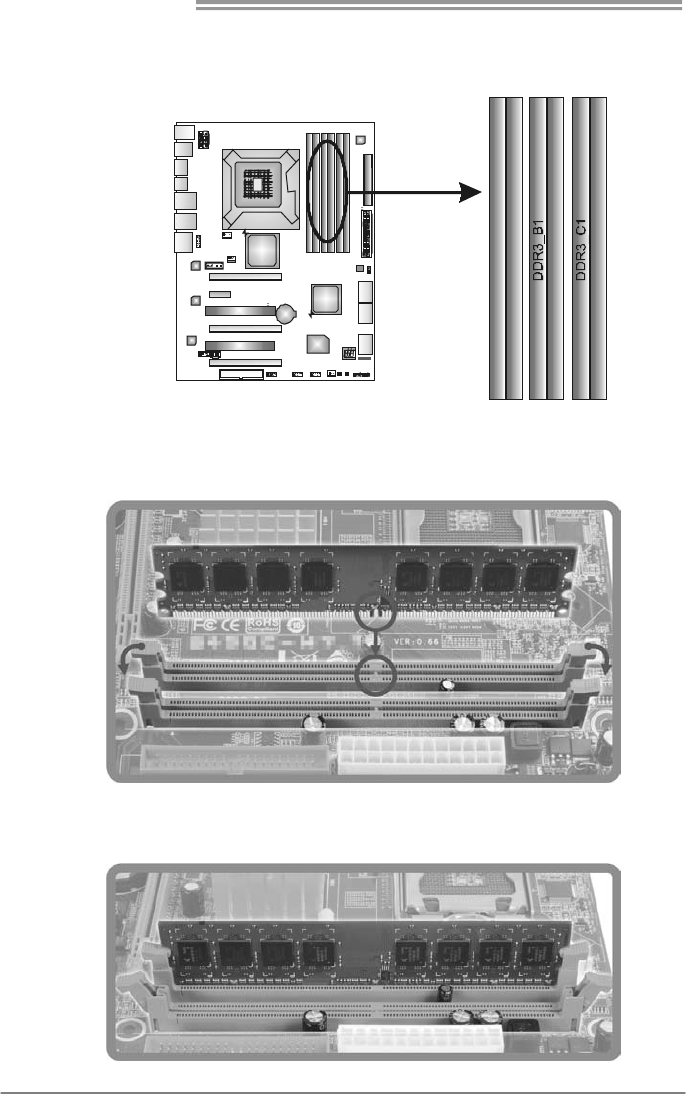
2.3 INSTALLING SYSTEM MEMORY
A. Memory Modules
DDR3_A1
DDR3_A2
DDR3_B2
DDR3_C2
1. Unlock a DIMM slot by pressing the retaining clips outward. Align a
DIMM on the slot such that the notch on the DIMM matches the
break on the Slot.
2. Insert the DIMM vertically and firmly into the slot until the retaining
chip snap back in place and the DIMM is properly seated.

TPower X58/TPower X58A
9
B. Memory Capacity
DIMM Socket
Location DDR3 Module Total Memory Size
DDR3_A1 256MB/512MB/1GB/2GB / 4GB
DDR3_A2 256MB/512MB/1GB/2GB / 4GB
DDR3_B1 256MB/512MB/1GB/2GB / 4GB
DDR3_B2 256MB/512MB/1GB/2GB / 4GB
DDR3_C1 256MB/512MB/1GB/2GB / 4GB
DDR3_C2 256MB/512MB/1GB/2GB / 4GB
Max is 24GB.
C. Triple Channel Memory installation
Triple Channel function will be activated as the following table shows:
(O means memory installed; X, not installed.)
Triple Channel
Status
DDR3
A1
DDR3
A2
DDR3
B1
DDR3
B2
DDR3
C1
DDR3
C2
Enabled X O X O X O
Enabled O O O O O O
The DRAM bus width of the memory module must be the same (x8 or x16)
Attention: Memory module must be installed in one of DDR3 channel _2 slots
(DDR3_A2, DDR3_B2, DDR3_C2) to boot the system.
Motherboard Manual
10
2.4 CONNECTORS AND SLOTS
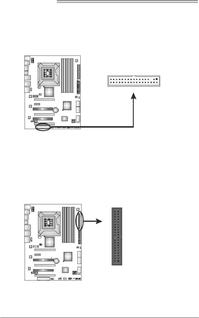
FDD1: Floppy Disk Connector
The motherboard provides a standard floppy disk connector that supports 360K,
720K, 1.2M, 1.44M and 2.88M floppy disk types. This connector supports the
provided floppy drive ribbon cables.
34
33 1
2
IDE1: IDE/ATAPI Connector
The motherboard has a 32-bit Enhanced PCI IDE Controller that provides PIO
Mode 0~4, Bus Master, and Ultra DMA 33/66/100/133 functionality.
The IDE connector can connect a master and a slave drive, so you can connect
up to two devices.
12
40 39
TPower X58/TPower X58A
11
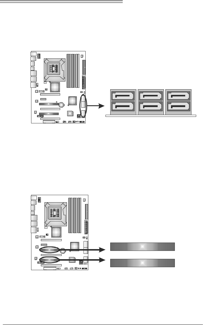
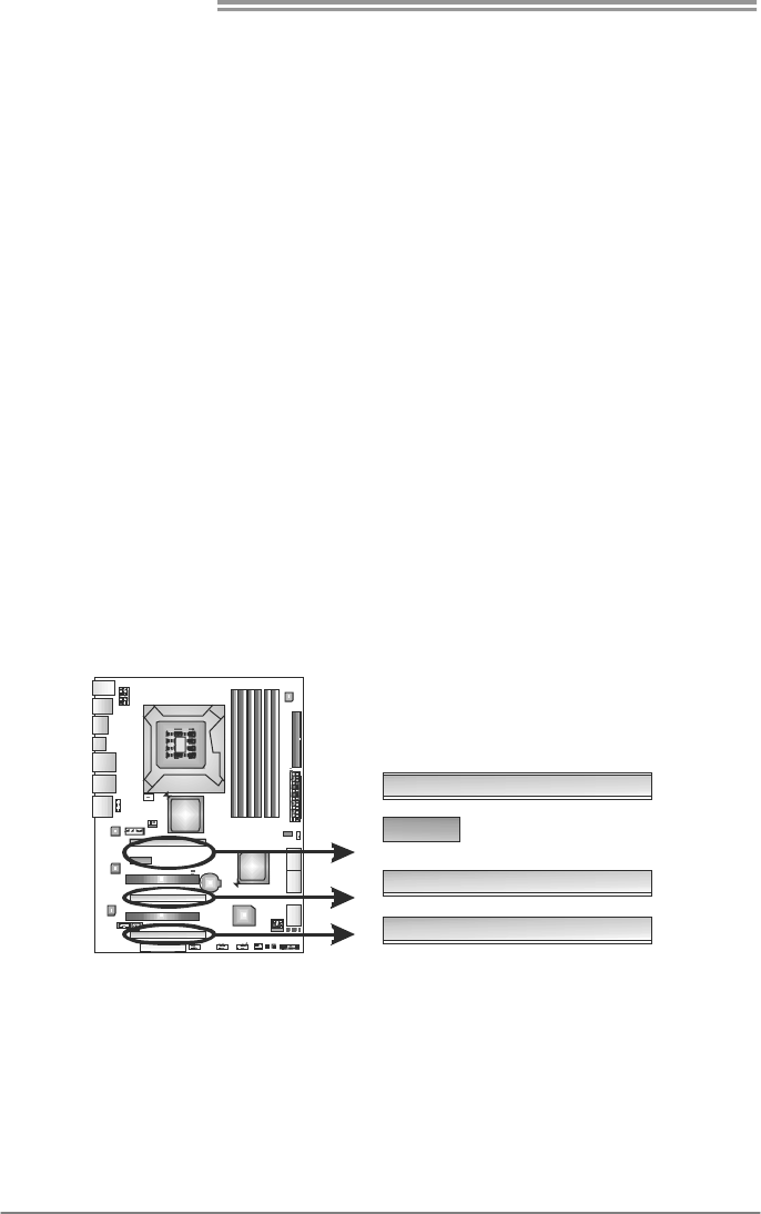
SATA1~SATA3: Serial ATA Connectors
The motherboard has a PCI to SATA Controller with 6 channels SATA interface,
it satisfies the SATA 2.0 spec and with transfer rate of 3.0Gb/s.
SATA3 SATA2 SATA1
PCI1/PCI2: Peripheral Component Interconnect Slots
This motherboard is equipped with 2 standard PCI slots. PCI stands for
Peripheral Component Interconnect, and it is a bus standard for expansion
cards. This PCI slot is designated as 32 bits.
PCI2
PCI1
Motherboard Manual
12
PEX16_1 & PEX16_2: PCI-Express Gen2 x16 (x16/CrossFire x16,
SLI x16 Speed) Slot
- PCI-Express 2.0 compliant.
- Maximum theoretical realized bandwidth of 8GB/s simultaneously per
direction, for an aggregate of 16GB/s totally.
- PEX16_1 & PEX16_2 slots are reserved for graphic or video cards. The
design of this motherboard supports dual PCI-Express graphics cards using
CrossFire technology with multiple displays. When CrossFire and SLI is
activated, these slots run with x16 speed.
PEX4_1: PCI-Express Gen2 x4 Slot
- PCI-Express 2.0 compliant.
- Maximum theoretical realized bandwidth of 1GB/s simultaneously per
direction, for an aggregate of 2GB/s totally.
- Some VGA cards may not work on this slot.
PEX1_1: PCI-Express x1 Slots
- PCI-Express 1.0a compliant.
- Data transfer bandwidth up to 250MB/s per direction; 500MB/s in total.
- PCI-Express supports a raw bit-rate of 2.5Gb/s on the data pins.
- 2X bandwidth over the traditional PCI architecture.
PEX16_1
PEX1_1
PEX16_2
PEX4_1
TPower X58/TPower X58A
13
CHAPTER 3: HEADERS & JUMPERS SETUP
3.1 HOW TO SETUP JUMPERS
The illustration shows how to set up jumpers. When the jumper cap is
placed on pins, the jumper is “close”, if not, that means the jumper is
“open”.
Pin opened Pin closed Pin1-2 closed
3.2 DETAIL SETTINGS
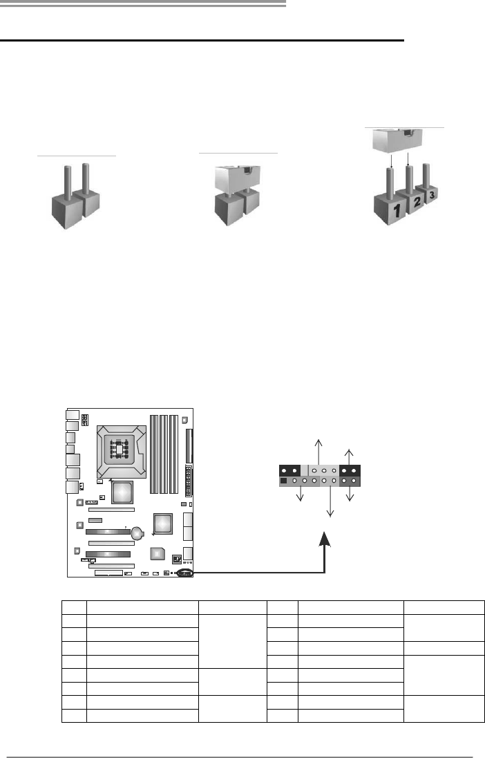
JPANEL1: Front Panel Header
This 16-pin connector includes Power-on, Reset, HDD LED, Power LED, and
speaker connection. It allows user to connect the PC case’s front panel switch
functions.
1
9
8
16
PWR_LED
On/Off
RST
HLED
SPK
++
+
-
-
Pin Assignment Function Pin Assignment Function
1 +5V 9 N/A
2 N/A 10 N/A N/A
3 N/A 1 1 N/A N/A
4 Speaker
Speaker
Connector
12 Power LED (+)
5 HDD LED (+) 13 Power LED (+)
6 HDD LED (-)
Hard drive
LED 14 Power LED (-)
Power LED
7 Ground 15 Power button
8 Reset control Reset button 16 Ground Power-on button
Motherboard Manual
14
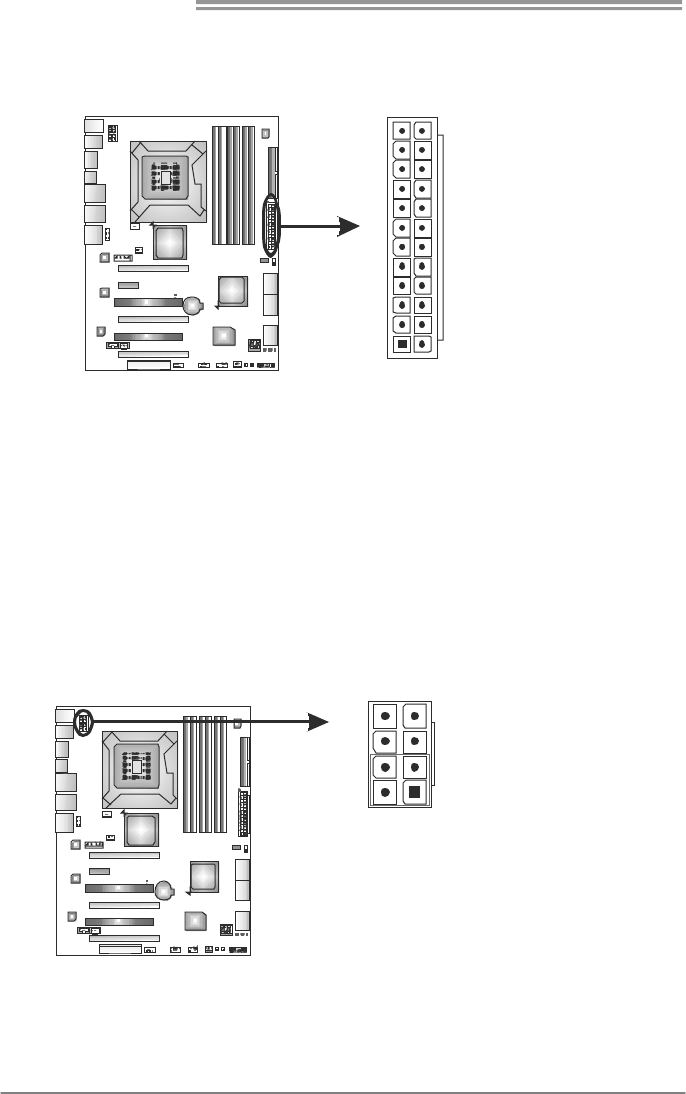
JATXPWR2: ATX Power Source Connector
This connector allows user to connect 24-pin power connector on the ATX
power supply.
1
12
13
24
Pin Assignment Pin Assignment
13 +3.3V 1 +3.3V
14 -12V 2 +3.3V
15 Ground 3 Ground
16 PS_ON 4 +5V
17 Ground 5 Ground
18 Ground 6 +5V
19 Ground 7 Ground
20 NC 8 PW_OK
21 +5V 9 Standby Voltage+5V
22 +5V 10 +12V
23 +5V 11 +12V
24 Ground 12 +3.3V
JATXPWR1: ATX Power Source Connector
This connector provides +12V to CPU power circuit.
Pin
Assignment
1 +12V
2 +12V
3 +12V
4 +12V
5 Ground
6 Ground
7 Ground
1
45
8
8 Ground
Note:
Before power on the system, please make sure that both JATXPWR1 and JATXPWR2
connectors have been plugged-in.
If the CPU power plug is 4-pin, please plug it into Pin 1-2-5-6 of JATXPWR1.
TPower X58/TPower X58A
15
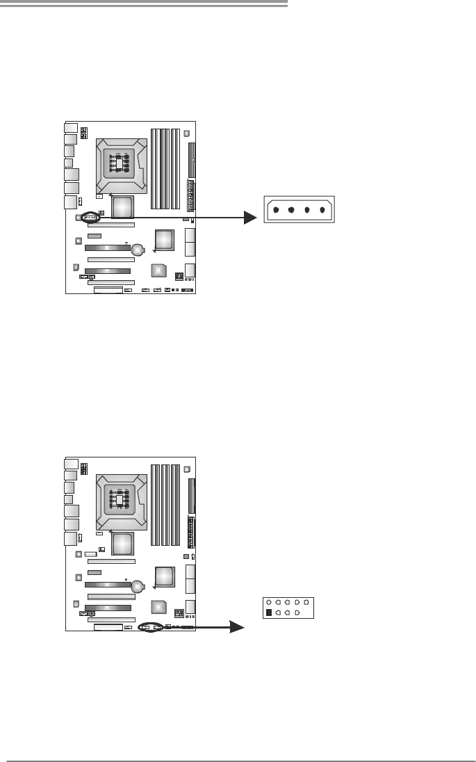
JATXPWR3: Auxiliary Power for Graphics
This connector is an auxiliary power connection for graphics cards. Exclusive
power for the graphics card provides better graphics performance.
Pin
Assignment
1 +12V
2 Ground
3 Ground
4 VCC
14
JUSB1/JUSB2: Headers for USB 2.0 Ports at Front Panel
Theses headers allow user to connect additional USB cable on the PC front
panel. They also can be connected with internal USB devices, like USB card
reader.
Pin
Assignment
1 +5V (fused)
2 +5V (fused)
3 USB-
4 USB-
5 USB+
6 USB+
7 Ground
8 Ground
9 Key
1
2
9
10
JUSB2JUSB1
10 NC
Motherboard Manual
16
JAUDIOF1: Front Panel Audio Header
This header allows user to connect the front audio output cable with the PC front
panel. This header allows only HD audio front panel connector; AC’97 connector
is not acceptable.
Pin
Assignment
1 Mic Left in
2 Ground
3 Mic Right in
4 GPIO
5 Right line in
6 Jack Sense
7 Front Sense
8 Key
9 Left line in
12
910
10 Jack Sense
JCDIN1: CD-ROM Audio-in Connector
This connector allows user to connect the audio source from the different
devices, like CD-ROM, DVD-ROM, PCI sound card, PCI TV turner card etc..
Pin
Assignment
1 Left Channel Input
2 Ground
3 Ground
14
4 Right Channel Input
TPower X58/TPower X58A
17
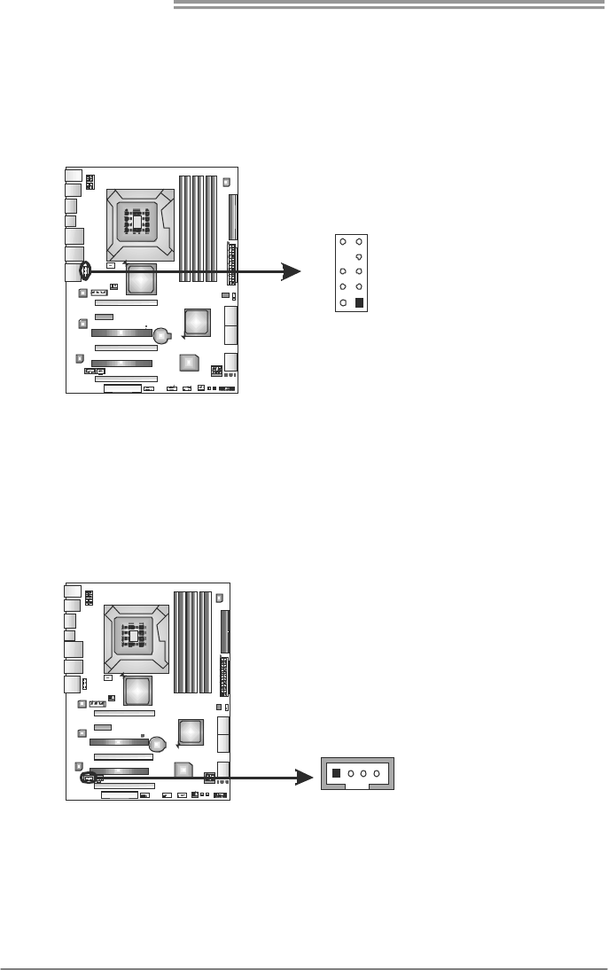
JSPDIF_OUT1: Digital Audio-out Connectors
JSPDIF_OUT1 is for connecting the PCI bracket SPDIF output.
Pin
Assignment
1 +5V
2 SPDIF_OUT
13
JSPDIF_OUT1
3 Ground
On-Board Buttons
There are 2 on-board buttons.
RSTSW1PWRSW1
PWRSW1:
This is an on-board Power Switch button.
RSTSW1:
This is an on-board Reset button.
Motherboard Manual
18
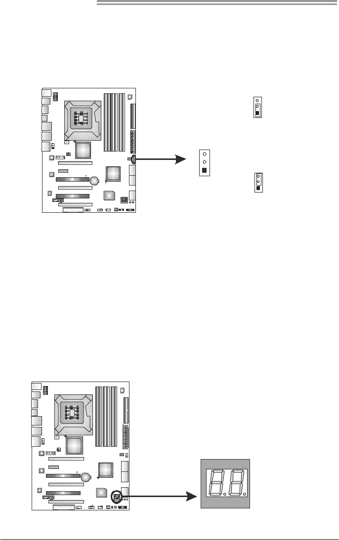
JCMOS1: Clear CMOS Header
Placing the jumper on pin2-3 allows user to restore the BIOS safe setting and
the CMOS data. Please carefully follow the procedures to avoid damaging the
motherboard.
1
3
Pin 1-2 Close:
Normal Operation (default).
1
3
1
3
Pin 2-3 Close:
Clear CMOS data.
※ Clear CMOS Procedures:
1. Remove AC power line.
2. Set the jumper to “Pin 2-3 close”.
3. Wait for five seconds.
4. Set the jumper to “Pin 1-2 close”.
5. Power on the AC.
6. Reset your desired password or clear the CMOS data.
BIOS POST Code
This indicator will show POST code while booting. Please refer to Chapter 6.4
for all the BIOS POST codes.
TPower X58/TPower X58A
19
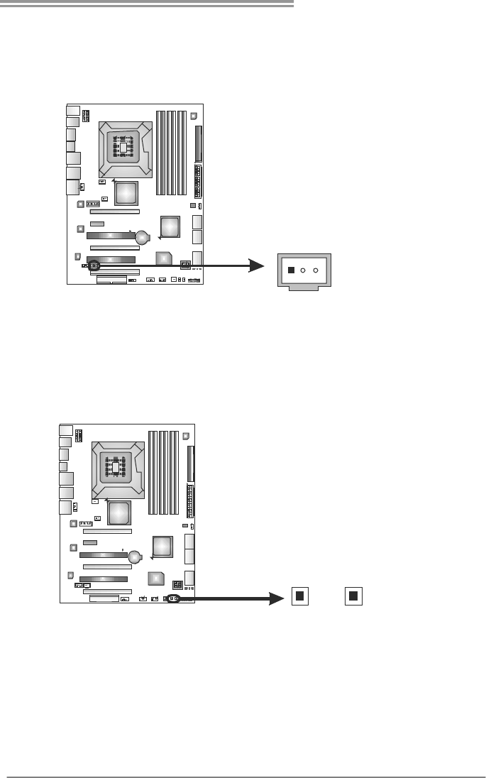
J1394_1: IEEE 1394 Header (TPower X58)
This header allows user to connect IEEE 1394 device.
Pin
Assignment
1 TPA1+
2 TPA1-
3 GND
4 GND
5 TPB1+
6 TPB1-
7 VCC
8 VCC
9 N/A
1
2
9
10
10 KEY
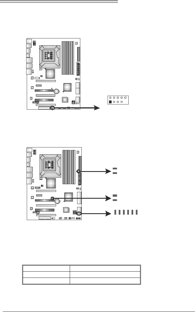
On-Board LED Indicators
There are 10 LED indicators on the motherboard showing system status.
PH_LED1
DDR_V_D1
DDR_V_D2
PH_LED2
PH_LED3
PH_LED5
PH_LED4
PH_LED6
NB_V_D2
NB_V_D1
DDR_V_D1 & DDR_V_D2: DDR Power Status Indicators
NB_V_D1 & NB_V_D2: NorthBridge Power Status Indicators
PH_LED1 ~ PH_LED6: CPU Power Status Indicators
Please refer to the tables below for different messages:
LED Phase Indicator
ON Phase Active
OFF Phase Disable
Note:
When power saving mode is activated, only one of DDR, of NB, and of CPU
LEDs will light.
Motherboard Manual
20
CHAPTER 4: RAID FUNCTIONS
4.1 OPERATING SYSTEM
Supports Windows XP / Vista 32 / Vista 64.
4.2 RAID ARRAYS
RAID supports the following types of RAID arrays:
RAID 0: RAID 0 defines a disk striping scheme that improves disk read and write times for
many applications.
RAID 1: RAID 1 defines techniques for mirroring data.
RAID 1+0 (Onboard): RAID 1+0 combines the techniques used in RAID 0 and RAID 1.
RAID 5 (Onboard): RAID 5 provides fault tolerance and better utilization of disk capacity.
4.3 HOW RAID WORKS
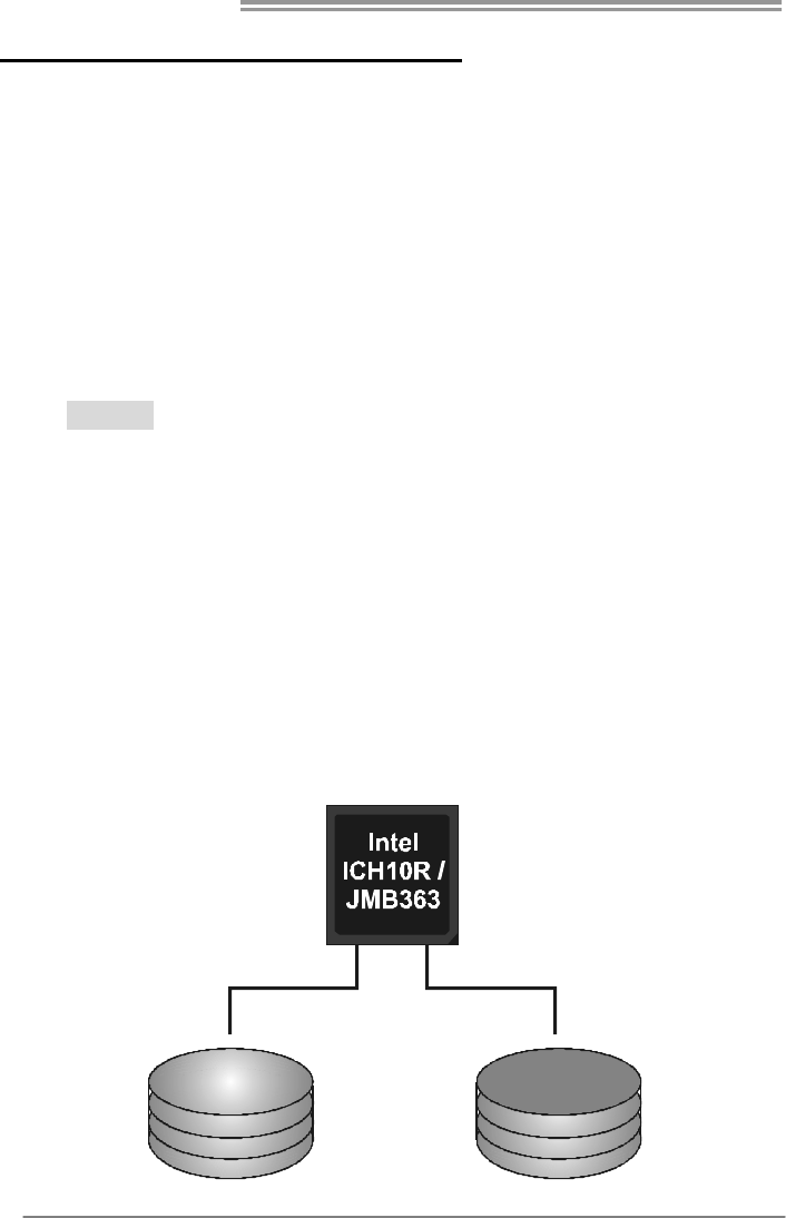
RAID 0:
The controller “stripes” data across multiple drives in a RAID 0 array system. It breaks
up a large f ile into smaller blocks and performs disk reads and writes across multip le
drives in parallel. The size of each block is determined by the stripe size parameter,
which you set during the creation of the RAID set based on the system environment. This
technique reduces overall disk access time and offers high bandwidth.
Features and Benefits
Drives: Minimum 2, and maximum is up to 6 or 8. Depending on the
platform.
Uses: Intended for non-critical data requiring high data throughput, or any
environment that does not require fault tolerance.
Benefits: provides increased data throughput, especially for large files. No
capacity loss penalty for parity.
Drawbacks: Does not deliver any fault tolerance. If any drive in the array
fails, all data is lost.
Fault Tolerance: No.
Block 1
Block 3
Block 5
Block 2
Block 4
Block 6
TPower X58/TPower X58A
21
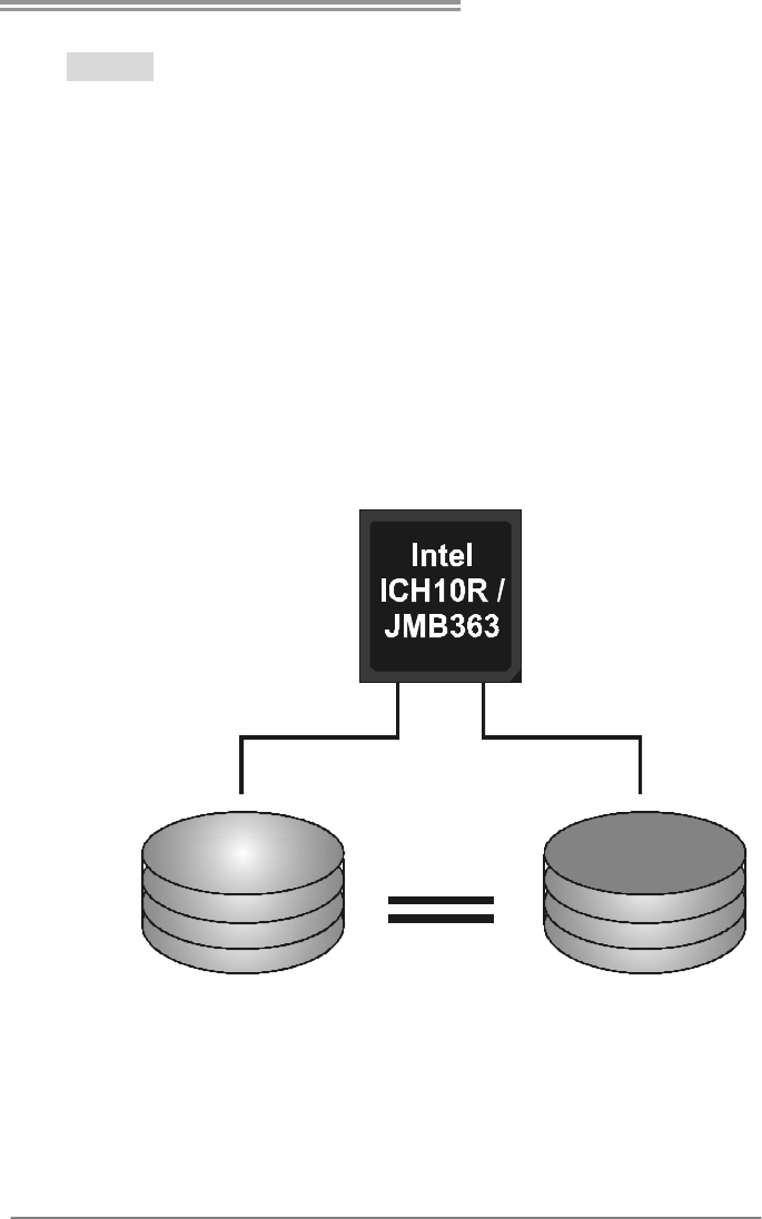
RAID 1:
Every read and write is actually carried out in parallel across 2 disk drives in a RAID 1
array system. The mirrored (backup) copy of the data can reside on the same disk or on a
second redundant drive in the array. RAID 1 provides a hot-standby copy of data if the
active volume or drive is corrupted or becomes unavailable because of a hardware failure.
RAID techniques can be applied for high-availability solutions, or as a form of automatic
backup that eliminates tedious manual backups to more expensive and less reliable
media.
Features and Benefits
Drives: Minimum 2, and maximum is 2.
Uses: RAID 1 is ideal for small databases or any other application that
requires fault tolerance and minimal capacity.
Benefits: Provides 100% data redundancy. Should one drive fail, the
controller switches to the other drive.
Drawbacks: Requires 2 drives for the storage space of one drive.
Performance is impaired during drive rebuilds.
Fault Tolerance: Yes.
Block 1
Block 2
Block 3
Block 1
Block 2
Block 3
Motherboard Manual
22
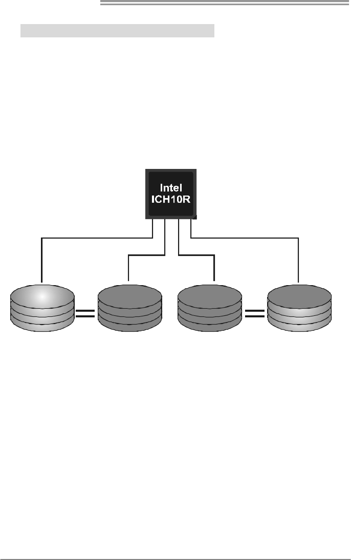
RAID 1+0 (For Onboard SATA Only):
RAID 1 drives can be stripped using RAID 0 techniques. Resulting in a RAID 1+0
solution for improved resiliency, performance and rebuild performance.
Features and Benefits
Drives: Minimum 4, and maximum is 6 or 8, depending on the platform.
Benefits: Optimizes for both fault tolerance and performance, allowing for
automatic redundancy. May be simultaneously used with other RAID levels
in an array, and allows for spare disks.
Drawbacks: Requires twice the available disk space for data redundancy,
the same as RAID level 1.
Fault Tolerance: Yes.
Block 1
Block 3
Block 5
Block 2
Block 4
Block 6
Block 1
Block 3
Block 5
Block 2
Block 4
Block 6
TPower X58/TPower X58A
23
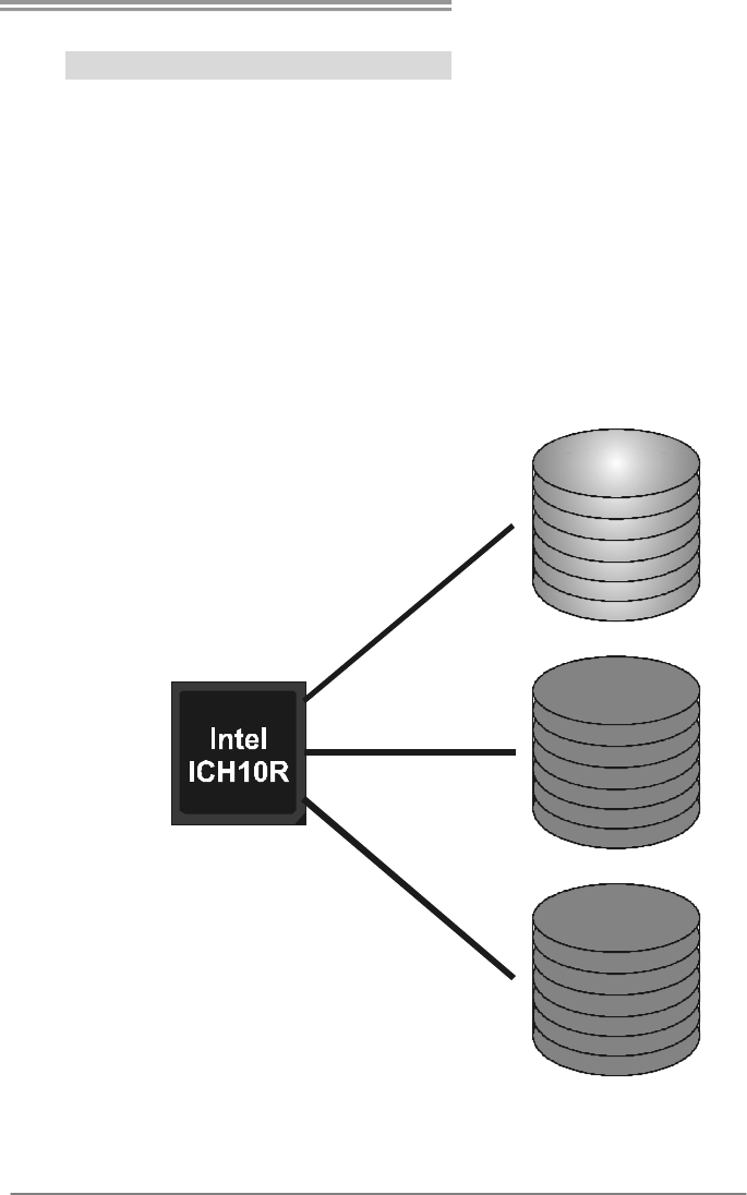
RAID 5 (For Onboard SATA Only):
RAID 5 stripes both data and parity information across three or more drives. It writes
data and parity blocks across all the drives in the array. Fault tolerance is maintained by
ensuring that the parity information for any given block of data is placed on a different
drive from those used to store the data itself.
Features and Benefits
Drives: Minimum 3.
Uses: RAID 5 is recommended for transaction processing and general
purpose service.
Benefits: An ideal combination of good performance, good fault tolerance,
and high capacity and storage efficiency.
Drawbacks: Individual block data transfer rate same as a single disk. Write
performance can be CPU intensive.
Fault Tolerance: Yes.
Disk 1
DATA 3
PA R IT Y
DATA 7
DATA 1
DATA 9
PA R IT Y
Disk 2
PA R IT Y
DATA 5
DATA 8
DATA 2
PA R IT Y
DATA 11
Disk 3
DATA 4
DATA 6
PA R IT Y
PA R IT Y
DATA 10
DATA 12
Motherboard Manual
24
CHAPTER 5: T-POWER BIOS & SOFTWARE
5.1 T-POWER BIOS
T-Power BIOS Features
Overclocking Navigator Engine (O.N.E.)
Memory Integration Test (M.I.T., under Overclock Navigator Engine)
BIO-Flasher: Update BIOS file from USB Flash Drive or FDD
Self Recovery System (S.R.S)
Smart Fan Function
CMOS Reloading Program
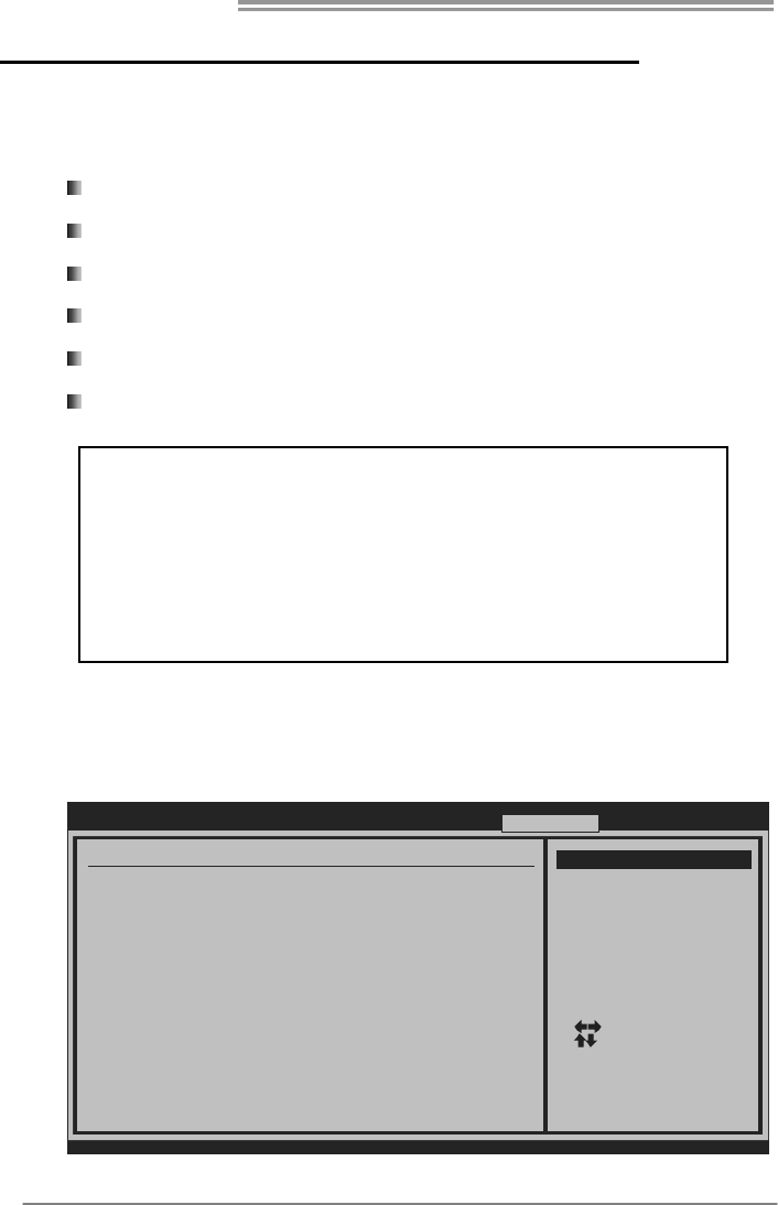
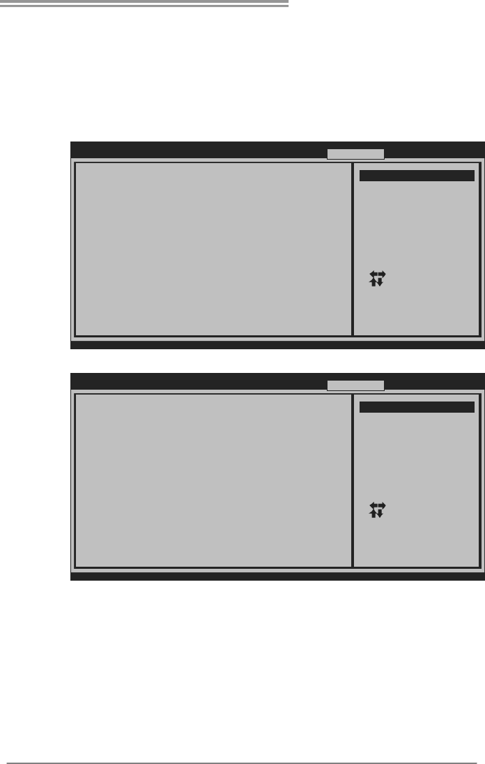
A. Overclocking Navigator Engine (O.N.E.)
ONE provides two powerful overclocking engines: MOS and AOS for both
Elite and Casual overclockers.
BIOS SETUP UTILITY
Main Advanced PCIPnP Boot Chipset O.N.E
vxx.xx (C)Copyright 1985-200x, American Megatrends, Inc.
Select Screen
Select Item
Go to Sub Screen
General Help
Save and Exit
Exit
Enter
F1
F10
ESC
Over-Clocking Navigator Setting
=========== Automate OverClock System ===========
============ Manual OverClock System ============
Over-Clocking Navigator [Normal]
Auto OverClock System [V6-Tech Engine]
Current QPI Frequency :
Current Memory Frequency :
Current Uncore Frequency :
Intel(R) SpeedStep(tm) tech [Enabled]
Ratio CMOS Setting [24]
CPU Frequency Setting [133]
QPI Links Speed [Full-Speed]
QPI Frequency [Auto]
Uncore Frequency [Auto]
DRAM Frequency [Auto]
Command Rate [Auto]
> Intel PPM/Turbo Mode Configuration
> DRAM Timing Configuration
Exit
Options
Normal
Automate OverClock
Manual OverClock
!! WARNING !!
For better system performance, the BIOS firmware is being
continuously updated. The BIOS information described below in
this manual is for your reference only and the actual BIOS
information and settings on board may be different from this
manual. For further information of setting up the BIOS, please
refer to the BIOS Manual in the Setu
p
CD.
TPower X58/TPower X58A
25
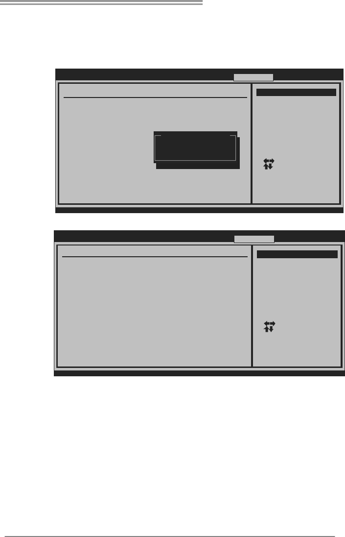
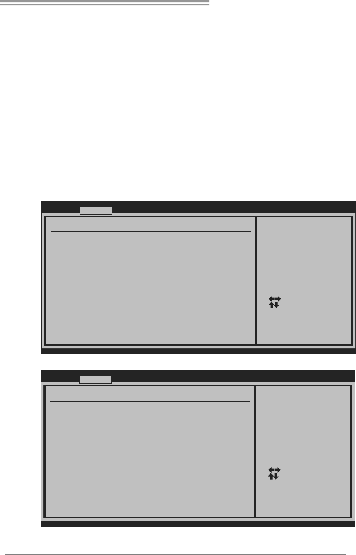
Manual Overclock System (M.O.S.)
MOS is designed for experienced overclock users.
It allows users to customize personal overclock settings.
BIOS SETUP UTILITY
Main Advanced PCIPnP Boot Chipset O.N.E
vxx.xx (C)C opyright 1985- 200x, Americ an Megatrends, Inc.
Select Screen
Select Item
Go to Sub Screen
General Help
Save and Exit
Exit
Enter
F1
F10
ESC
Over-Clocking Navigator Setting
=========== Automate OverClock System ===========
============ Manual OverClock System ============
Over-Clocking Navigator [Normal]
Auto OverCl ock System [ V6-Tech Engi ne]
Current QPI Frequency :
Current Memory Frequency :
Current Uncore Frequency :
Intel(R) SpeedStep(tm) tech [Enabled]
Ratio CMOS Setting [24]
CPU Frequency Setting [133]
QPI Links Speed [Full-Speed]
QPI Frequency [Auto]
Uncore Frequency [Auto]
DRAM Freque ncy [Au to]
Command Rate [Auto]
> Intel PPM/Turbo Mode Configuration
> DRAM Timing Configuration
Exit
Opti ons
Normal
Automate OverClock
Manual Over Clock
Options
Normal
Automate O verClock
Manual OverClock
↓
BIOS SETUP UTILIT
Y
Main Advanced PCIPnP Boot Ch ipset O.N.E
vxx.xx (C)Copyright 1985-200x, American Megatrends, Inc.
Select Screen
Select Item
Go to Sub Scre en
General Help
Save and Exit
Exit
Enter
F1
F10
ESC
Over-Clocking Navigator Setting
=========== Automate OverClock System ===========
============ Manual OverClock System ============
Over-Clocking Navigator [Manual OverClock]
Intel(R) SpeedStep(tm) tech [Enabled]
Ratio CMOS Se tting [2 4]
CPU Frequency Setting [133]
QPI Links Speed [Full-Speed]
QPI Frequency [Auto]
Uncore Frequency [Auto]
DRAM Frequency [Auto]
Command Rate [Auto]
> Intel PPM/Turbo Mode Configuration
> DRAM Timing Configuration
Auto OverClock System [V6-Tech Engine]
Current QPI Frequency :
Current Memory Frequency :
Current Uncore Frequency :
Exit
Opti ons
Normal
Automate Ov erClock
Manual Over Clock
Intel(R) SpeedStep(tm) Tech
This item allows you to enable SpeedStep technology for better power
saving. SpeedStep is a technology built into some Intel processors that
allows the clock speed of the processor to be dynamically changed by
software.
Ratio CMOS Setting
This item allows you to set the CPU ratio frequency. This item is
adjustable only when SpeedStep Tech is set to Disabled.
CPU Fre quency Setting
CPU Frequency is directly in proportion to system performance. To
maintain the system stability, CPU voltage needs to be increased also
when raising CPU frequency.

Motherboard Manual
26
QPI Links Speed
This item allows you to set the QPI links to full-speed or leave them in
slow-mode..
QPI Fre quency
This item allows you to select the QPI Frequency.
Uncore Fre que ncy
This item allows you to select Uncore Frequency.
DRAM Freque ncy
This item allows you to control the Memory Clock.
Command Rate
This item allows you to select DRAM command rate.
Intel PPM/Turbo Mo de Co nfig uration
Enter this item for more advanced Intel PPM/Turbo settings.
DRAM Timing Configuration
Enter this item for more advanced DRAM timing settings.
Clock Ge n Co nfigurat io n
Enter this item for more advanced Clock Gen settings.
Voltage Control
Enter this item for more advanced voltage settings.
NOTE
Overclock is an optional process, but not a “must-do” process; it is not
recommended for inexperienced users. Therefore, we will not be responsible
for any hardware damage which may be caused by overclocking. We also
would not guarantee any overclocking performance.
TPower X58/TPower X58A
27
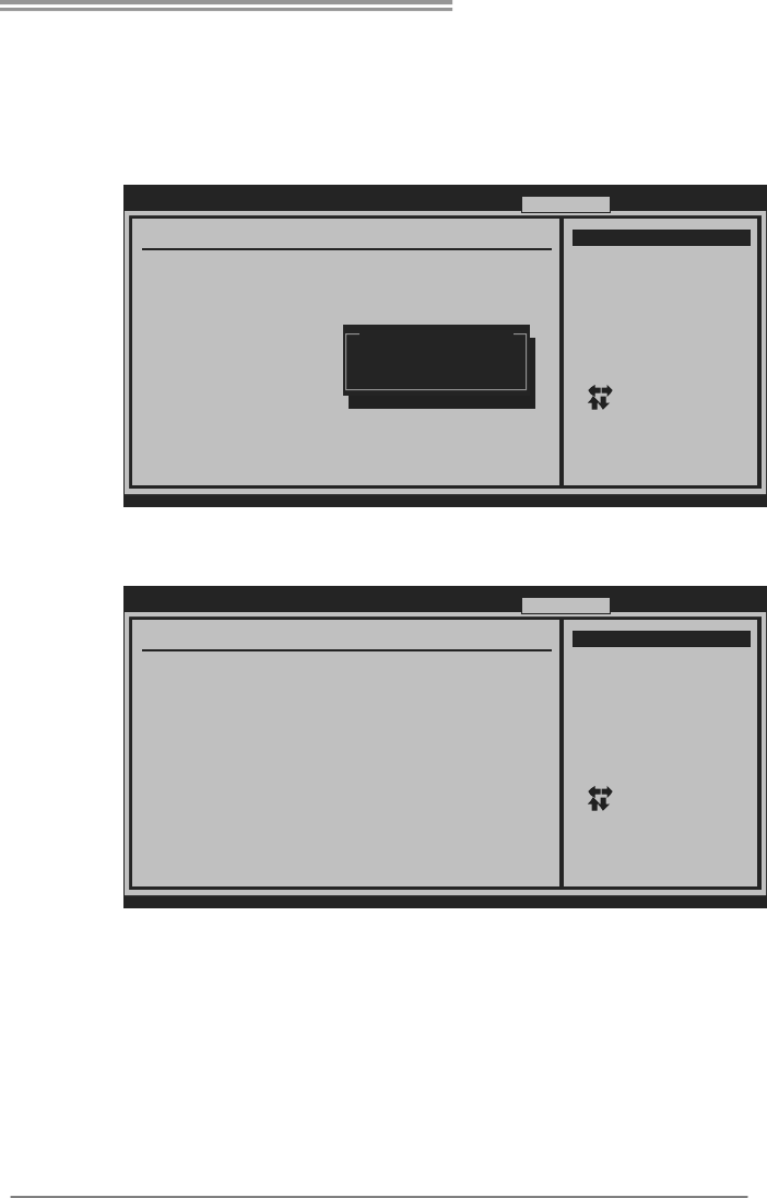
Automatic Overclock System (A.O.S.)
For beginners in overclock field, BET had developed an easy, fast, and
powerful feature to increase the system performance, named A.O.S.
Based on many tests and experiments, A.O.S. provides 3 ideal overclock
configurations that are able to raise the system performance in a single step.
BIOS SETUP UTILIT
Y
Main Advanced PCIPnP Boot Chipset O.N.E
vxx.xx (C)C opyright 1985- 200x, Americ an Megatrends , Inc.
Select Screen
Select Item
Go to Sub Screen
General Help
Save and Exit
Exit
Enter
F1
F10
ESC
Over-Clocking Navigator Setting
=========== Automate OverClock System ===========
============ Manual OverClock System ============
Over-Clocking Navigator [Normal]
Auto OverCl ock System [ V6-Tech Engi ne]
Current QPI Frequency :
Current Memory Frequency :
Current Uncore Frequency :
Intel(R) SpeedStep(tm) tech [Enabled]
Ratio CMOS Setting [24]
CPU Frequency Setting [133]
QPI Links Speed [Full-Speed]
QPI Frequency [Auto]
Uncore Frequency [Auto]
DRAM Freque ncy [Au to]
Command Rate [Auto]
> Intel PPM/Turbo Mode Configuration
> DRAM Timing Configuration
Exit
Opti ons
Normal
Automate OverClock
Manual Over Clock
Options
Normal
Manual OverClock
Automate O verClock
V6 Tech Engine
This engine will make a good over-clock performance.
BIOS SETUP UTILIT
Y
Main Advanced PCIPnP Boot Chipset O.N.E
vxx.xx (C)C opyright 1985- 200x, Americ an Megatrends , Inc.
Select Screen
Select Item
Go to Sub Screen
General Help
Save and Exit
Exit
Enter
F1
F10
ESC
Over-Clocking Navigator Setting
=========== Automate OverClock System ===========
============ Manual OverClock System ============
Over-Clocking Navigator [Automate OverClock]
Auto OverCl ock System [ V6-Tech Engi ne]
Current QPI Frequency :
Current Memory Frequency :
Current Uncore Frequency :
Intel(R) SpeedStep(tm) tech [Enabled]
Ratio CMOS Setting [24]
CPU Frequency Setting [133]
QPI Links Speed [Full-Speed]
QPI Frequency [Auto]
Uncore Frequency [Auto]
DRAM Freque ncy [Au to]
Command Rate [Auto]
> Intel PPM/Turbo Mode Configuration
> DRAM Ti ming Confi guration
Exit
Opti ons
V6-Tech Engine
V8-Tech Engine
V12-Tech Engine
Motherboard Manual
28
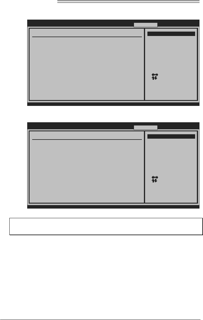
V8 Tech Engine
This engine will make a better over-clock performance.
BIOS SETUP UTILIT
Y
Main Advanced PCIPnP Boot Chipset O.N.E
vxx.xx (C)C opyright 1985- 200x, Americ an Megatrends , Inc.
Select Screen
Select Item
Go to Sub Screen
General Help
Save and Exit
Exit
Enter
F1
F10
ESC
Over-Clocking Navigator Setting
=========== Automate OverClock System ===========
============ Manual OverClock System ============
Over-Clocking Navigator [Automate OverClock]
Auto OverCl ock System [ V8-Tech Engi ne]
Current QPI Frequency :
Current Memory Frequency :
Current Uncore Frequency :
Intel(R) SpeedStep(tm) tech [Enabled]
Ratio CMOS Setting [24]
CPU Frequency Setting [133]
QPI Links Speed [Full-Speed]
QPI Frequency [Auto]
Uncore Frequency [Auto]
DRAM Freque ncy [Au to]
Command Rate [Auto]
> Intel PPM/Turbo Mode Configuration
> DRAM Ti ming Confi guration
Exit
Opti ons
V6-Tech Engine
V8-Tech Engine
V12-Tech Engine
V12 Tech Engine
This engine will make a best over-clock performance.
BIOS SETUP UTILIT
Y
Main Advanced PCIPnP Boot Chipset O.N.E
vxx.xx (C)C opyright 1985- 200x, Americ an Megatrends , Inc.
Select Screen
Select Item
Go to Sub Screen
General Help
Save and Exit
Exit
Enter
F1
F10
ESC
Over-Clocking Navigator Setting
=========== Automate OverClock System ===========
============ Manual OverClock System ============
Over-Clocking Navigator [Automate OverClock]
Auto OverClock System [V12-Tech Engine]
Current QPI Frequency :
Current Memory Frequency :
Current Uncore Frequency :
Intel(R) SpeedStep(tm) tech [Enabled]
Ratio CMOS Setting [24]
CPU Frequency Setting [133]
QPI Links Speed [Full-Speed]
QPI Frequency [Auto]
Uncore Frequency [Auto]
DRAM Freque ncy [Au to]
Command Rate [Auto]
> Intel PPM/Turbo Mode Configuration
> DRAM Ti ming Confi guration
Exit
Opti ons
V6-Tech Engine
V8-Tech Engine
V12-Tech Engine
Notices:
Not all types of Intel CPU perform above overclock setting ideally; the difference will be based on the
selected CPU model.
TPower X58/TPower X58A
29
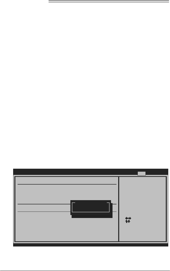
B. Memory Integration Test (M.I.T.)
This function is under “Overclocking Navigator Engine” item.
MIT allows users to test memory compatibilities, and no extra devices or
software are needed.
Step 1
The default setting under this item is “Disabled”; the condition parameter should
be changed to “Enable” to proceed this test.
BIOS SETUP UTILIT
Y
Main Advanced PCIPnP Boot Ch ipset O.N.E
vxx.xx (C)Copyright 1985-200x, American Megatrends, Inc.
Select Screen
Select Item
Go to Sub Scre en
General Help
Save and Exit
Exit
Enter
F1
F10
ESC
=========== Automate OverClock System ===========
============ Manual OverClock System ============
Auto OverClock System [V6-Tech Engine]
DRAM Timing Configuration
Clock Gen Configuration
Current QPI Frequency :
Current Memory Frequency :
Current Uncore Frequency :
Intel(R) SpeedStep(tm) tech [Enabled]
Ratio CMOS Se tting [2 4]
CPU Frequency Setting [133]
QPI Links Speed [Full-Speed]
QPI Frequency [4.800GT]
Uncore Frequency [Auto]
DRAM Frequency [Auto]
Command Rate [Auto]
> Intel PPM/Turbo Mode Configuraiton
>
>
> Voltage Control
Memory Test [Disabled]
Exit
Opti ons
Disabled
Enabled
↓
BIOS SETUP UTILIT
Y
Main Advanced PCIPnP Boot Ch ipset O.N.E
vxx.xx (C)Copyright 1985-200x, American Megatrends, Inc.
Select Screen
Select Item
Go to Sub Scre en
General Help
Save and Exit
Exit
Enter
F1
F10
ESC
=========== Automate OverClock System ===========
============ Manual OverClock System ============
Auto OverClock System [V6-Tech Engine]
Current QPI Frequency :
Current Memory Frequency :
Current Uncore Frequency :
Intel(R) SpeedStep(tm) tech [Enabled]
Ratio CMOS Se tting [2 4]
CPU Frequency Setting [133]
QPI Links Speed [Full-Speed]
QPI Frequency [4.800GT]
Uncore Frequency [Auto]
DRAM Frequency [Auto]
Command Rate [Auto]
> Intel PPM/Turbo Mode Configuraiton
>
>
> Voltage Control
DRAM Timing Configuration
Clock Gen Configuration
Memory Test [Enabled]
Exit
Opti ons
Disabled
Enabled
Step 2
Save and Exit from CMOS setup and reboot the system to activate this test.
Run this test for 5 minutes (minimum) to ensure the memory stability.
Step 3
When the process is done, change the setting back from “Enable” to “Disable”
to complete the test.
Motherboard Manual
30
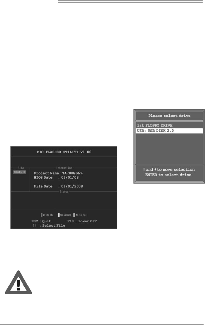
C. BIO-Flasher
BIO-Flasher is a BIOS flashing utility providing you an easy and simple way to
update your BIOS via USB pen drive or floppy disk.
The BIO-Flasher is built in the BIOS chip. To enter the utility, press <F12>
during the Power-On Self Tests (POST) procedure while booting up.
Updating BIOS with BIO-Flasher
1. Go to the website to download the latest BIOS file for the motherboard.
2. Then, save the BIOS file into a USB pen drive or a floppy disk.
3. Insert the USB pen drive or the floppy disk that contains the BIOS file to the
USB port or the floppy disk drive.
4. Power on or reset the computer and then
press <F12> during the POST process.
A select dialog as the picture on the right
appears.
Select the device contains the BIOS file and
press <Enter> to enter the utility.
5. The utility will show the BIOS
files and their respective
information. Select the proper
BIOS file and press <Enter>
then <Y> to perform the BIOS
update process.
6. After the update process, the utility will ask you to reboot the system.
Press <Y> to proceed. BIOS update completes.
z This utility only allows storage device with FAT32/16 format and single
partition.
z Shutting down or resetting the system while updating the BIOS will lead to
system boot failure.
TPower X58/TPower X58A
31
D. Self Recovery System (S.R.S.)
This function can’t be seen under BIOS setup; and is always on whenever the
system starts up.
However, it can prevent system hang-up due to inappropriate overclock
actions.
When the system hangs up, S.R.S. will automatically log in the default BIOS
setting, and all overclock settings will be re-configured.
E. Smart Fan Function
Smart Fan Function is under “Smart Fan Configuration” in “Advanced Menu”.
This is a brilliant feature to control CPU/System Temperature vs. Fan speed.
When enabling Smart Fan function, Fan speed is controlled automatically by
CPU/System temperature.
This function will protect CPU/System from overheat problem and maintain the
system temperature at a safe level.
BIOS SETUP UTILITY
Main Advanced PCIPnP Boot Chipset O.N.E
vxx.xx (C)Copyright 1985-200x, American Megatrends, Inc.
Select Screen
Select Item
Go to Sub Screen
General Help
Save and Exit
Exit
Enter
F1
F10
ESC
Configure CPU.Advanced Settings
WARNING: Setting wrong values in below sections
may cause system to malfunction.
> CPU Configuration
> Onboard PCI/PCI-E Devices Configuration
> Event Log Configuration
> Intel VT-d Configuration
> SuperIO Configuration
> Hardware Health Configuration
> USB Configuration
> PM/ACPI Configuration
> Smart Fan Configuration
Exit
↓
BIOS SETUP UTILITY
Advanced
vxx.xx (C)Copyright 1985-200x, American Megatrends, Inc.
Select Screen
Select Item
Change Option
General Help
Save and Exit
Exit
+-
F1
F10
ESC
When you choice [Auto]
, please run the
calibration to define
the Fan parameters for
Smart Fan control
Smart Fan Configuration
CPU Smart Fan [Disabled]
Smart Fan Calibration
Control Mode
Fan Ctrl OFF( C)
o
Fan Ctrl On( C)
Fan Ctrl Start value
Fan Ctrl Sensitive
o
Motherboard Manual
32
Smart Fan Calibration
Choose this item and then the BIOS will automatically test and detect the
CPU/System fan functions and show CPU/System fan speed.
Fan Ctrl OFF(℃)
If the CPU/System temperature is lower than the set value, the CPU/
System fan will turn off. The range is from 0~127, with an interval of 1.
Fan Ctrl On(℃)
The CPU/System fan starts to work when CPU/System temperature
arrives to this set value. The range is from 0~127, with an interval of 1.
Fan Ctrl Full On(℃)
If the System Temperature reaches the set value, FAN will run in full speed.
The range is from 0~127, with an interval of 1.
Fan Ctrl Start Value
When CPU/System temperature arrives to the set value, the CPU/System
fan will work under Smart Fan Function mode. The range is from 0~127,
with an interval of 1.
F. CMOS Reloading Program
It allows users to save different CMOS settings into BIOS-ROM.
Users are able to reload any saved CMOS setting for customizing system
configurations. Moreover, users are able to save an ideal overclock setting
during overclock operation.
There are 10 sets of record addresses in total, and users are able to name the
CMOS data according to personal preference.
BIOS SETUP UTILITY
Main Advanced PCIPnP Boot Chipset O.N.E
vxx.xx (C)Copyright 1985-200x, American Megatrends, Inc.
Select Screen
Select Item
Go to Sub Screen
General Help
Save and Exit
Exit
Enter
F1
F10
ESC
Exit Options
Security Settings
Save Changes and Exit
Discard Changes and Exit
Discard Changes
Load Optimal Defaults
> Security
CMOS Backup Function
Exit
CMOS Backup Func
CMOS Data
CMOS Data Reload
Save
TPower X58/TPower X58A
33
5.2 T-POWER SOFTWARE
T-Power2 is an integration of four functions: OC Tweaker for over-clock,
eHot-Line for technical support, BIOS-watch for system monitor, and Biostar
Flash for BIOS update.
Installing T-Power2
1. Insert the Setup CD to the optical drive. The drivers installation program
would appear if the Autorun function has been enabled.
2. Select Software Installation, and then click on T-Power2.
3. Follow the on-screen instructions to complete the installation.
Launching T-Power2
After the installation process, you will see a “TPower2” icon
appears on the desktop. Double-click the TPower2 icon to
launch T-Power2 utility.
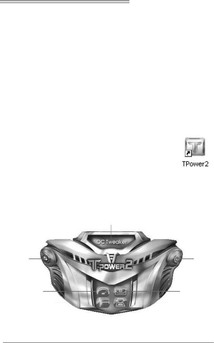
Main Panel
The main panel provides OC Tweaker, eHot-Line, BIO-watch, and Biostar
Flash buttons for launching the respective programs. Besides you can also
change the skin of the main panel.
Thi s area sh ows the inf ormati o
n
of the pointed button
Program OFFCh an ge Sk in
eHOT-LineOC Tweaker
Biostar FlashBIO-wa tch
Motherboard Manual
34
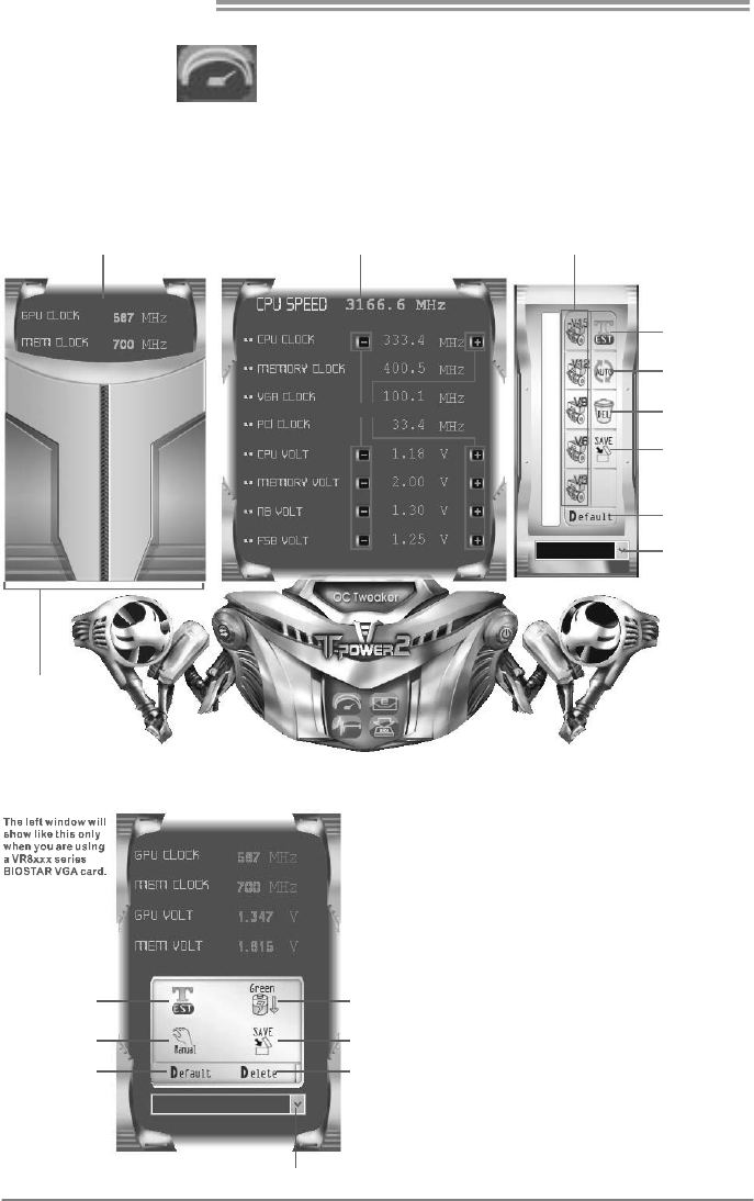
Power Saving ModeTes t th e VGA car d
Delete current
VGA s etting file
Load previous saved
VGA setting file
Manual over-clock
Re stor e VGA car d
default setting
Save current
VGA s etting into file
OC Tweaker
On the main panel, you can click on the OC Tweaker button to launch this
function. The OC Tweaker provides automatic/manual over-clock function for
BIOSTAR motherboard, and even for some BIOSTAR VGA card (VR8xxx
series only) which is powered by V-Ranger.
This area shows clo ck
information of th e VGA card
This area shows clock/voltag
e
information of the CPU/motherboard
Man ual Adju st
V3/V6/V9/V12/V15
Fixed mode over-clock
Te st the system
Auto over- clock
Delete curre nt
se tti ng file
Save current
setting into file
Re store hardware
default setting
Load previously
sa ve d sett in g fi le
If you are not using a
nVIDI A VGA ca rd, th is
windo w will not show.
If your have installed a
V-Ranger powered BIOSTAR
VGA card, then the left
window of the VGA card
information would show like
this. VGA card over-clock
function will be enabled.
TPower X58/TPower X58A
35
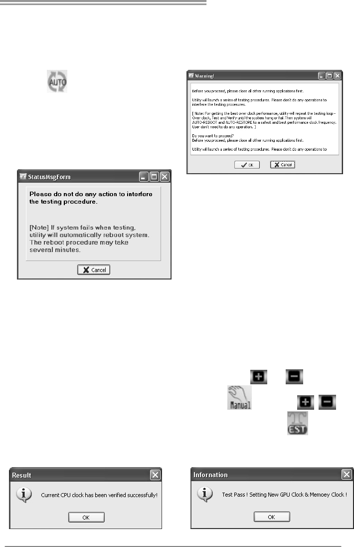
<Auto Over-clock>
By this function, the utility will set the best and stable performance and
frequency automatically.
Click on then a Warning dialog will
show. This dialog tells that all running
applications should be closed before the auto
over-clock procedure. The utility will do a
series of test continually; do not do any
operation during the test procedure. Click OK
to proceed or Cancel to stop.
After proceeding the tests would start, and a
warning message would continually show
telling that do not do any action to interfere
the testing procedure. The testing
procedure takes minutes; you can stop the
procedure by clicking Cancel.
For getting the best performance, the utility will repeat the test continually until the system
hang or fail, and then the system will auto-reboot. After that, launch the T-Power2 and enter
the OC Tweaker again, you will find the setting has been restored to a safest and best
performance status. Save this setting is recommended.
<Manual Over-clock>
To manually adjust the clock and voltage, just click the or beside the
number. (For V-Ranger powered VGA card, click then the
beside the VGA values will show.) After the adjustment, click to verify
the supplied value is recommended. If the test passes, following dialog will
show; click OK to proceed.
Motherboard Manual
36
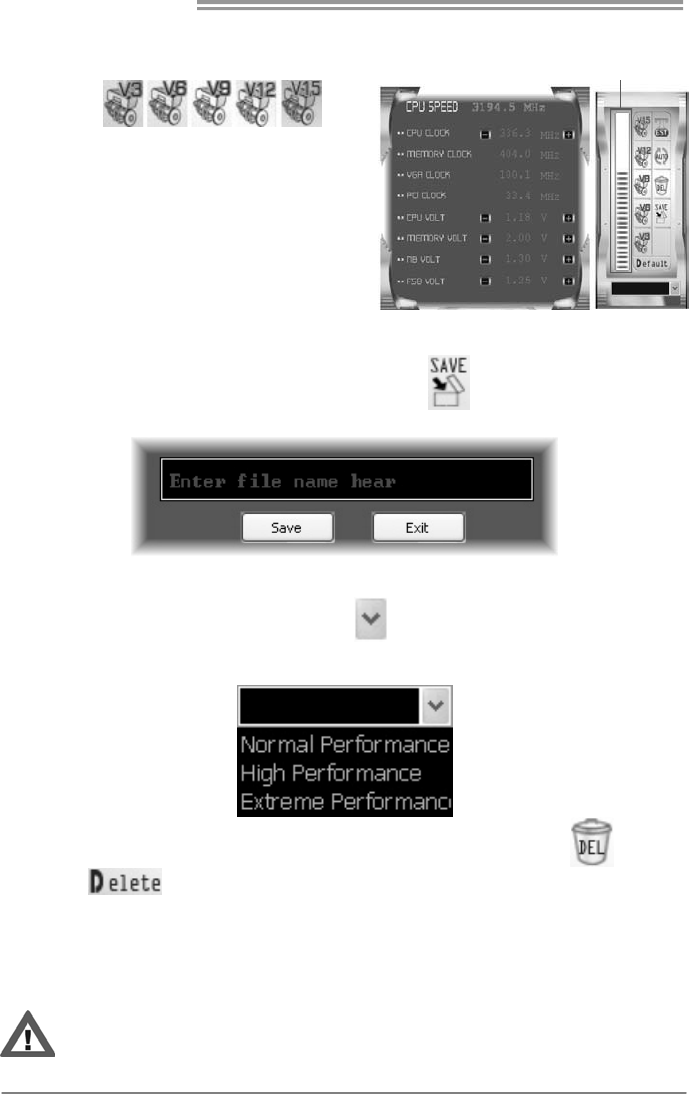
EX: This means V9 engine is activated.
<V3/V6/V9/V12/V15 Engine>
By clicking ,
the utility would over-clock the system
with certain fixed percentage. When the
V3/V6/V9/V12/V15 engine is activated,
you will see the green light bar on the left
rising to the top of the button.
This function is recommended for
any inexperienced users.
<Save/Load/Delete Setting>
You can save current setting to a file by clicking , then a dialog as bellow
will show.
Enter file name and click “Save”, and then the current setting would be saved.
To load a previously saved file, click on , and the saved files would show
as bellow. Click on the file name and then choose “Yes” to load the setting.
To delete a previously saved file; load the setting first Æ click on (for VGA
setting is ) Æ choose “Yes”, and the setting file will be deleted.
(Be aware of that VGA setting for V-Ranger powered VGA card must be
saved/loaded/deleted respectively.)
Over-clock is an optional process but not a “must-do” process, and actual over-clock
result varies by every individual PC system. Therefore, we will neither guarantee any
over-clock performance nor be responsible for any system damage that may be caused
by over-clock. Any values or performance shown above are for reference only.
TPower X58/TPower X58A
37
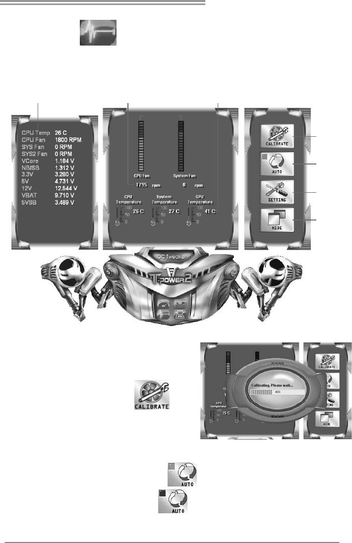
BIO-watch
BIO-watch is a control and monitor utility that helps you to maintain the health
of the PC. It provides real-time information of CPU/GPU/System temperature,
fan speed, and voltage; and fan control function.
This area shows real-time information of
temperature/fan speed/voltage
Fa n co nt ro l b ar s
Current fan speed Current CPU/GPU/System temperatu re
Fa n
calibrate
Fa n
auto-control
ON/OFF
Fa n
co ntrol setti ng
Hide
this utili ty
<Fan Calibrate>
At the very first time entering this utility,
fan calibrate will be made automatically.
After that you can also click to
manually calibrate the fan.
<Fan Auto/Manual Control>
When the “AUTO” button looks like , it means fans are under
auto-control. Click the button to then you can manually adjust fan
speed.
Motherboard Manual
38
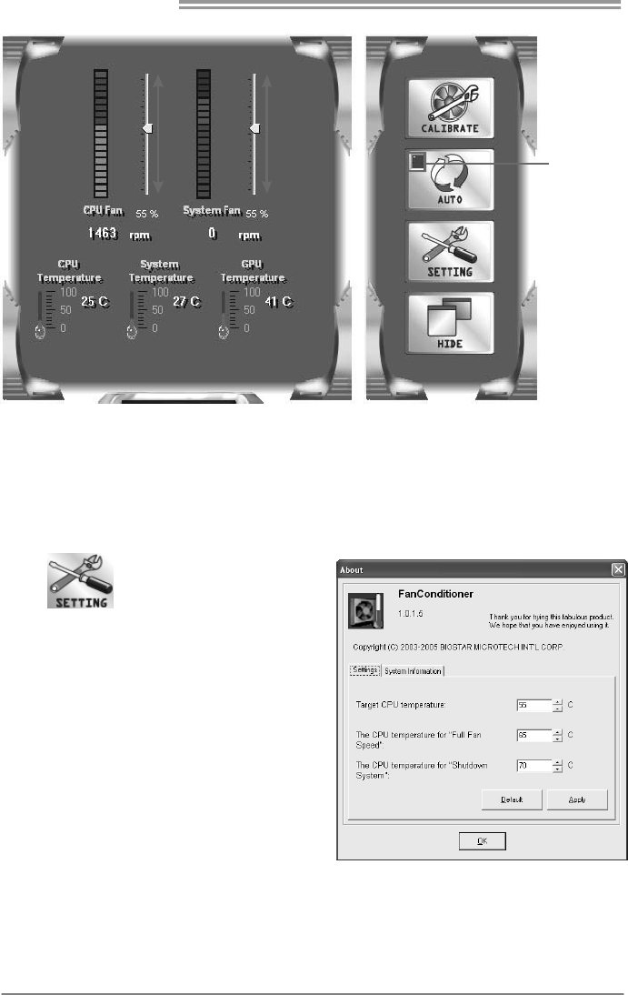
Auto-Control
OFF
Increase Speed
Decrease Speed
Click the auto-control off and then the adjust level will show; use the level to
increase/decrease the fan speed. Be aware if the fan level been down to 0%,
the fan will still not completely stop; this is for your system’s protection.
<Fan Control Settings>
Click to enter the fan control
setting dialog. Here you can set CPU
temperature to control the fan; including
target CPU temperature, CPU
temperature for full fan speed, and CPU
temperature for shutdown system.
Besides, you can also see system
information in this dialog.
TPower X58/TPower X58A
39
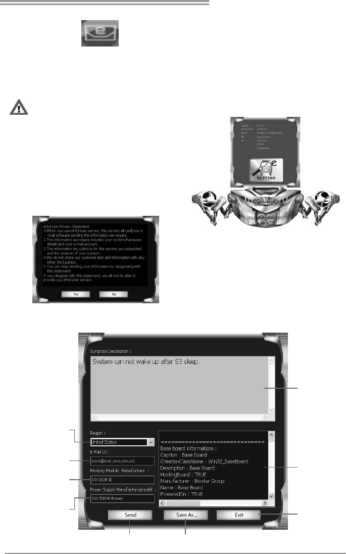
eHot-Line
eHot-Line is a convenient utility that helps you to contact with our
Tech-Support system. This utility will collect the system information which is
useful for analyzing the problem you may have encountered, and then send
these information to our tech-support department to help you fix the problem.
Before you use this utility, please set Outlook Express as your default e-mail client application program.
The main panel of eHot-Line shows
BIOS information, motherboard model
name, and chipset information, click on
“SETTING” to enter.
The Privacy Statement shows; and
please read through it. If you agree
with the statement, click “Yes” to
proceed; If not, click “No” to leave.
After agreeing with the privacy statement, fill up the table in the following dialog.
Descri be conditi on
of your system.
This block will show
the info rmation which
would be collected in
the mail .
Select your area or
the area close to you.
Provide the e-mail
addr ess that you wo uld
like to send the copy to.
Pro vid e the name of
the memory module
manufacturer.
Pro vide the name of
th e power supply
manuf actur er and the
model no.
Send the mail out
.
Save these infor mation t o a .txt file
Exit this dialog.
*
*
*
*
represents important
information that you
must provide. Without
this information, you may
not be able to send out
the mail.
Motherboard Manual
40
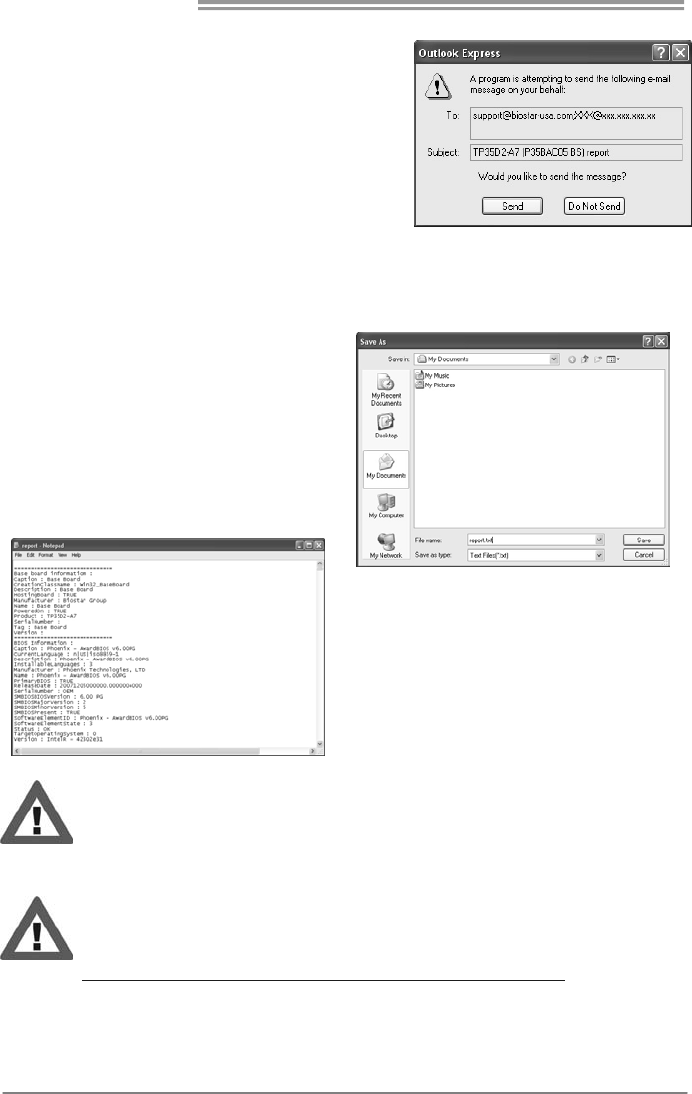
After filling up this information, click “Send”
to send the mail out. A warning dialog would
appear asking for your confirmation; click
“Send” to confirm or “Do Not Send” to cancel.
If you want to save this information to a .txt file, click “Save As…” and then you
will see a saving dialog appears asking you to enter file name.
Enter the file name and then click
“Save”. Your system information
will be saved to a .txt file.
Open the saved .txt file, you will see
your system information including
motherboard/BIOS/CPU/video/
device/OS information. This
information is also concluded in the
sent mail.
We will not share customer’s data with any other third parties,
so please feel free to provide your system information while using
eHot-Line service.
If you are not using Outlook Express as your default e-mail client
application, you may need to save the system information to a .txt file
and send the file to our tech support with other e-mail application.
Go to the following web
http://www.biostar.com.tw/app/en-us/about/contact.php for getting
our contact information.
TPower X58/TPower X58A
41
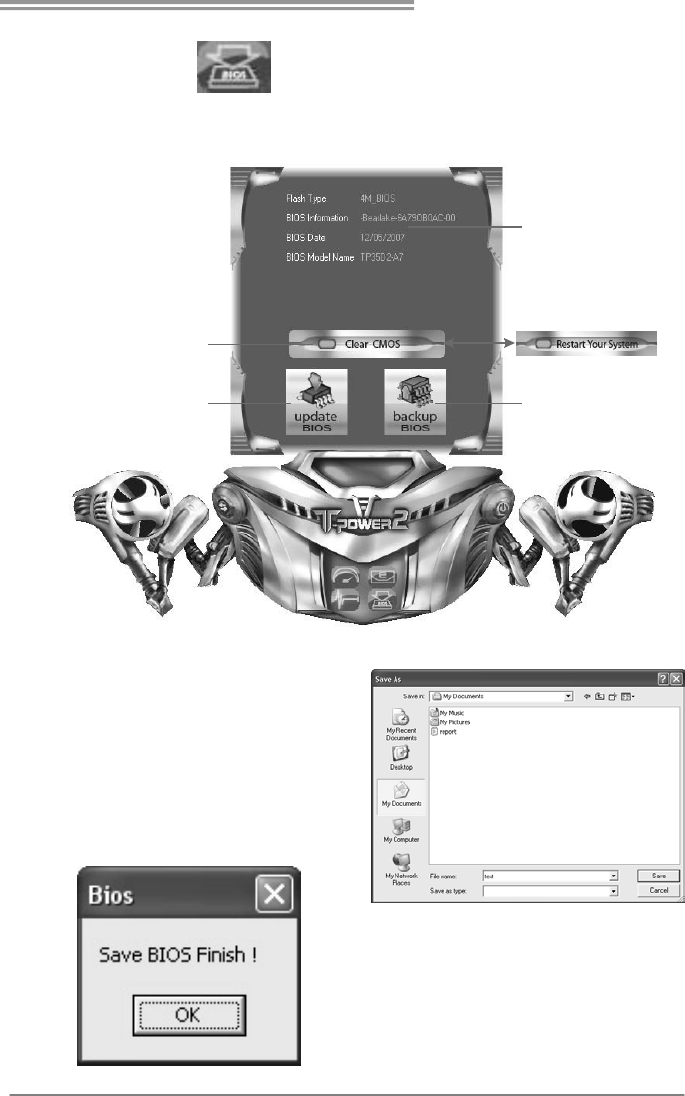
Biostar Flash
Biostar Flash is a conve nie nt utility which allows you to update yo ur
motherboard BIOS under Windows system.
Update BIOS
with a B IOS fil e
Clear CMOS function
(Award BIOS)
Shows current BIOS
information
Save current BIOS
to a .bin file
Restart Your System
(AMI BIOS)
or
<Backup BIOS>
Once click on this button, the saving
dialog will show. Choose the
position to save file and enter file
name. (We recommend that the file
name should be English/number
and no longer than 7 characters.)
Then click Save.
After the saving process, finish
dialog will show. Click on OK to
complete the BIOS Backup
procedure.

Motherboard Manual
42
<Update BIOS>
Before doing this, please download the proper BIOS file from our website:
www.biostar.com.tw
Update BIOS procedure should be run with
Clear CMOS (or Restart) function, so please
check on Clear CMOS (or Restart) first.
(Restart Your System)
Then click Update BIOS button, a
dialog will show for asking you backup
current BIOS. Click Yes for BIOS
backup and refer to the Backup BIOS
procedure; or click No to skip this
procedure.
After the BIOS Backup procedure, the
open dialog will show for requesting the
BIOS file which is going to be updated.
Please choose the proper BIOS file for
updating, then click on Open.
The utility will update BIOS with the
proper BIOS file.
After the BIOS Update process, click on
OK to restart the system.
While the system boots up and the full screen logo shows, press <Delete>
key to enter BIOS setup.
In the BIOS setup, choose Load Optimized Defaults and press
<Enter>Æ<Y>Æ<Enter>. After that use Save and Exit Setup to exit BIOS setup.
BIOS Update is completed.
All the information and content above about the T-Power 2 utility are subject to be
changed without notice. For better performance, the utility is being continuously
updated. The information and pictures described above are for your reference only.
The actual information and settings on board may be slightly different from this
manual.
TPower X58/TPower X58A
43
CHAPTER 6: USEFUL HELP
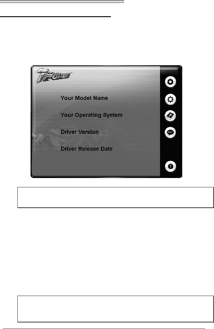
6.1 DRIVER INSTALLATION NOTE
After you installed your operating system, please insert the Fully Setup
Driver CD into your optical drive and install the driver for better system
performance.
You will see the following window after you insert the CD
The setup guide will auto detect your motherboard and operating system.
Note:
If this window didn’t show up after you insert the Driver CD, please use file browser to
locate and execute the file SETUP.EXE under your optical drive.
A. Driver Installation
To install the driver, please click on the Driver icon. The setup guide will
list the compatible driver for your motherboard and operating system.
Click on each device driver to launch the installation program.
B. Software Installation
To install the software, please click on the Software icon. The setup guide
will list the software available for your system, click on each software title
to launch the installation program.
C. Manual
Aside from the paperback manual, we also provide manual in the Driver
CD. Click on the Manual icon to browse for available manual.
Note:
You will need Acrobat Reader to open the manual file. Please download the latest version
of Acrobat Reader software from
http://www.adobe.com/products/acrobat/readstep2.html

Motherboard Manual
44
6.2 EXTRA INFORMATION
CPU Overheated
If the system shutdown automatically after power on system for
seconds, that means the CPU protection function has been activated.
When the CPU is over heated, the motherboard will shutdown
automatically to avoid a damage of the CPU, and the system may not
power on again.
In this case, please double check:
1. The CPU cooler surface is placed evenly with the CPU surface.
2. CPU fan is rotated normally.
3. CPU fan speed is fulfilling with the CPU speed.
After confirmed, please follow steps below to relief the CPU protection
function.
1. Remove the power cord from power supply for seconds.
2. Wait for seconds.
3. Plug in the power cord and boot up the system.
Or you can:
1. Clear the CMOS data.
(See “Close CMOS Header: JCMOS1” section)
2. Wait for seconds.
3. Power on the system again.

TPower X58/TPower X58A
45
6.3 AMI BIOS BEEP CODE
Boot Block Beep Codes
Number of Beeps Description
1 No media present. (Insert diskette in floppy drive A:)
2 “AMIBOOT.ROM” file not found in root directory of diskette in
A:
3 Insert next diskette if multiple diskettes are used for recovery
4 Flash Programming successful
5 File read error
7 No Flash EPROM detected
10 Flash Erase error
11 Flash Program error
12 “AMIBOOT.ROM” file size error
13 BIOS ROM image mismatch (file layout does not match
image present in flash device)
POST BIOS Beep Codes
Number of Beeps Description
1 Memory refresh timer error
3 Base memory read/write test error
6 Keyboard controller BAT command failed
7 General exception error (processor exception interrupt error)
8 Display memory error (system video adapter)
Troubleshooting POST BIOS Beep Codes
Number of Beeps Troubleshooting Action
1, 3 Reseat the memory, or replace with known good modules.
6, 7
Fatal error indicating a serious problem with the system.
Consult your system manufacturer. Before declaring the
motherboard beyond all hope, eliminate the possibility of
interference by a malfunctioning add-in card. Remove all
expansion cards except the video adapter.
z If beep codes are generated when all other expansion
cards are absent, consult your system manufacturer’s
technical support.
z If beep codes are not generated when all other expansion
cards are absent, one of the add-in cards is causing the
malfunction. Insert the cards back into the system one at a
time until the problem happens again. This will reveal the
malfunctioning card.
8
If the system video adapter is an add-in card, replace or
reseat the
video adapter. If the video adapter is an integrated part of the
system board, the board may be faulty.

Motherboard Manual
46
6.4 AMI BIOS POST CODE
Checkpoint Description
03
Disable NMI, Parity, video for EGA, and DMA controllers. Initialize BIOS,
POST, Runtime data area . Also initiali ze B IOS modules on POST e ntry and
GPNV area. Initialized CMOS as mentioned in the Kernel Variable
"wCMOSFlags."
04
Check CMOS diagnostic byte to determine if battery power is OK and
CMOS checksum is OK. Verify CMOS checksum manually by reading
storage area. If the CMOS checksum is bad, update CMOS with power-on
default values and clear passwords. Initialize status register A.
Initializes data variables that are based on CMOS setup questions.
Initializes both the 8259 compatible PICs in the system
05 Initializes the interrupt controlling hardware (generally PIC) and interrupt
vector table.
06
Do R/W test to C H-2 count reg. Initiali ze CH-0 as s ystem timer. Install the
POSTINT1Ch handler. E nable IRQ-0 in PIC for syste m timer interrupt.
Traps INT1Ch vector to "POSTINT1ChHandlerBlock."
07 Fixes CPU POST interface calling pointer.
08
Initiali zes the CPU. The BAT test is bei ng do ne on KBC. Program the
keyboard controller command byte is being done after Auto detection of
KB/MS using AMI KB-5.
C0 Early CPU Init Start -- Disable Cache – Init Local APIC.
C1 Set up boot strap processor Information.
C2 Set up boot strap processor for POST.
C5 Enumerate and set up application processors.
C6 Re-enable cache for boot strap processor.
C7 Early CPU Init Exit.
0A Initializes the 8042 compatible Key Board Controller.
0B Detects the presence of PS/2 mouse.
0C Detects the presence of Keyboard in KBC port.
0E
Testing and initialization of different Input Devices. Also, update the Kernel
Variables.
Traps the INT09h vector, so that the POST INT09h hand ler gets co ntrol for
IRQ1. Uncompress all available language, BIOS logo, and Silent logo
modules.
13 Early POST initialization of chipset registers.
20 Relocate System Management Interrupt vector for all CPU in the system.
24 Uncompress and i nitialize any platform specific BIOS modules. GPNV is
initialized at this checkpoint.
2A Initializes different devices through DIM.
See DIM Code Checkpoints section of document for more information.
2C Initializes different devices. Detects and initializes the video adapter
installed in the system that have optional ROMs.
2E Initializes all the output devices.
31
Allocate memory for ADM module and uncompress it. Give control to ADM
module for initialization. Initialize language and font modules for ADM.
Activate ADM module.
33 Initializes the silent boot module. Set the window for displaying text
informa tion.

TPower X58/TPower X58A
47
Checkpoint Description
37 Displaying sign-on message, CPU information, setup key message, and any
OEM specific information.
38
Initializes different devices through DIM. See DIM Code Checkpoints section
of document for more information. USB controllers are initialized at this
point.
39 Initializes DMAC-1 & DMAC-2.
3A Initialize RTC date/time.
3B Test for total memory installed in the system. Also, Check for DEL or ESC
keys to limit memory test. Display total memory in the system.
3C Mid POST initialization of chipset registers.
40
Detect different devices (Parallel ports, serial ports, and coprocessor in
CPU, etc.) successfully installed in the system and update the BDA,
EBDA…etc.
52
Updates CMOS memory size from memory found in memory test. Allocates
memory for Extended BIOS Data Area from base memory. Programming the
memory hole or any kind of implementation that needs an adjustment in
system RAM size if needed.
60 Initializes NUM-LOCK status and programs the KBD typematic rate.
75 Initialize Int-13 and prepare for IPL detection.
78 Initializes IPL devices controlled by BIOS and option ROMs.
7C Generate and write contents of ESCD in NVRam.
84 Log errors encountered during POST.
85 Display errors to the user and gets the user response for error.
87 Execute BIOS setup if needed / requested. Check boot password if installed.
8C Late POST initialization of chipset registers.
8D Build ACPI tables (if ACPI is supported).
8E Program the peripheral parameters. Enable/Disable NMI as selected.
90 Initialization of system management interrupt by invoking all handlers.
Please note this checkpoint comes right after checkpoint 20h.
A1 Clean-up work needed before booting to OS.
A2
Takes care of runtime image preparation for different BIOS modules. Fill the
free area in F000h segment with 0FFh. Initializes the Microsoft IRQ Routin
g
Table. Prepares the runtime language module. Disables the system
configuration display if needed.
A4 Initialize runtime language module. Display boot option popup menu.
A7 Displays the system configuration screen if enabled. Initialize the CPU’s
before boot, which includes the programming of the MTRR’s.
A9 Wait for user input at config display if needed.
AA Uninstall POST INT1Ch vector and INT09h vector.
AB Prepare BBS for Int 19 boot. Init MP tables.
AC End of POST initialization of chipset registers. De-initializes the ADM
module.
B1 Save system context for ACPI. Prepare CPU for OS boot including final
MTRR values.
00 Passes control to OS Loader (typically INT19h).

Motherboard Manual
48
6.5 TROUBLESHOOTING
Problems Solutions
1. There is no power in the system.
Power LED does not shine; the
fan of the power supply does not
work
2. Indicator light on keyboard does
not shine.
1. Make sure power cable is
securely plugged in.
2. Replace cable.
3. Contact technical support.
System is inoperative. Keyboard lights
are on, power indicator lights are lit,
and hard drives are running.
Using even pressure on both ends of
the DIMM, press down firmly until the
module snaps into place.
System does not boot from a hard disk
drive, but can be booted from optical
drive.
1. Check cable running from disk to
disk controller board. Make sure
both ends are securely plugged
in; check the drive type in the
standard CMOS setup.
2. Backing up the hard drive is
extremely important. All hard
disks are capable of breaking
down at any time.
System only boots from an optical
drive. Hard disks can be read,
applications can be used, but system
fails to boot from a hard disk.
1. Back up data and applications
files.
2. Reformat the hard drive.
Re-install applications and data
using backup disks.
Screen message shows “Invalid
Configuration” or “CMOS Failure.”
Review system’s equipment. Make sure
correct information is in setup.
System cannot boot after user installs a
second hard drive.
1. Set master/slave jumpers
correctly.
2. Run SETUP program and select
correct drive types. Call the drive
manufacturers for compatibility
with other drives.

TPower X58/TPower X58A
49
This page is intentionally left blank.

Motherboard Manual
50
APPENDIX: SPEC IN OTHER LANGUAGES
GERMAN
Spezifikationen
CPU SOCKET 1366
Intel Cor e i7 Ex treme / Core i7 Prozessoren
Unterstützt Execute Disable Bit / Enhanced Intel
SpeedStep® / Intel Architecture-64 / Extended
Memory 64 Technology / Virtualization Technology /
Hyp er Thread ing
QPI 6.4GT/s
Chipsatz Intel X58
Intel ICH10R
Super E/A
IT8720
Bietet die häufig verwendeten alten Super
E/A-Funktionen.
Low Pin Count-Schnittstelle
Umgebungskontrolle,
Hardware-Überwachung
Lüfterdrehzahl-Controller/-Überwachung
"Smart Guardian"-Funktion von ITE
Arbeitsspeich
er
DDR3 DIMM-Steckplätze x 6
Jeder DIMM unterstützt 512MB / 1GB / 2GB
/ 4GB DDR3.
Max. 24GB Arbeitsspeicher
Dual & Dreier Kanal DDR3 Speichermodul
Unterstützt DDR3 1866(OC) / 1600(OC) / 1333 /
1066 / 800
registrierte DIMMs. ECC DIMMs werden nicht
unterstützt.
IDE JMB363 Ultra DMA 33 / 66 / 100 / 133 Bus Master-Modus
Unterstützt PIO-Modus 0~4,
SATA II ICH10R
Datentransferrate bis zu 3Gb/s
Konform mit der SATA-Spezifikation Version 2.0.
Unterstützt RAID 0 / 1 / 5 / 1+0
eSATA JMB363
Datentransferrate bis zu 3Gb/s
Konform mit der SATA-Spezifikation Version 2.0.
Unterstützt Port-Multiplier/RAID 0,1
LAN Realtek RTL 8111C x2 (TPower X58)
Realtek RTL 8111C x1 (TPower X58A)
10 / 100 / 1000 Mb/s Auto-Negotiation
Halb-/ Vollduplex-Funktion
HD
Audio-Unters
tützung
ALC888S Unterstützt High-Definition Audio
7.1-Kanal-Audioausgabe
IEEE 1394 Ti tsb43ab22a (TPower X58)
PCI-Steckplatz x2 Steckplätze
PCI Express Gen2 x16 Steckplatz
(x16) x2

TPower X58/TPower X58A
51
Spezifikationen
PCI Express Gen2 x16 Steckplatz
(x4) x1
PCI Express x1 Steckplatz x1
Diskettenlaufwerkanschluss x1 Jeder Anschluss unterstützt 2 Diskettenlaufwerke
IDE-Anschluss x1 Jeder Anschluss unterstützt 2 IDE-Laufwerke
SATA-Anschluss x6 Jeder Anschluss unterstützt 1 SATA-Laufwerk
Fronttafelanschluss x1 Unterstützt die Fronttafelfunktionen
Front-Audioanschluss x1 Unterstützt die Fronttafel-Audioanschlussfunktion
CD-IN-Anschluss x1 Unterstützt die CD Audio-In-Funktion
S/PDIF Ausgangsanschluss x1 Unterstützt die digitale Audioausgabefunktion
CPU-Lüfter-Sockel x1
CPU-Lüfterstromversorgungsanschluss (mit Smart
Fan-Fun kt ion )
System-Lüfter-Sockel x2 System-Lüfter-Stromversorgungsanschluss
"CMOS löschen"-Sockel x1
USB-Anschluss x2
Jeder Anschluss unterstützt 2
Fronttafel-USB-Anschlüsse
IEEE 1394-Anschluss (TPower X58) x1
Stromanschluss (24-polig) x1
Stromansch luss (8-polig ) x1
Onboard-Ans
chluss
Stromansch luss (4-polig ) x1
Rückseiten-E
/A
PS/2-Tastatur x1
LAN-Anschluss x2
USB-Anschluss x8
Audioanschluss x6
eSATA Anschluss x2
1394-Anschluss (TPower X58) x1
Optisches +coaxial S/PDIF heraus x1
Platinengröße
244 mm (B) X 305 mm (L) ATX
OS-Unterstüt
zung Windows XP / Vista 32 / Vista 64
Biostar behält sich das Recht vor, ohne Ankündigung
die Unterstützung für ein Betriebssystem
hinzuzufügen oder zu entfernen.

Motherboard Manual
52
FRENCH
SPEC
UC
SOCKET 1366
Processeurs Intel Core i7 Extreme /
Core i7
Prend en charge les techno log ies d'exécution de bit de
désactivation / Intel SpeedStep® opt imisée/
d'architecture Intel 64 / de mémoire étendu e 64 / de
virtualisation / Hyper Threading
QPI 6.4GT/s
Chipset Intel X58
Intel ICH10R
Super E/S
IT8720
Fournit la fonctionnalité de Super E/S
patrimoniales la plus utilisée.
Interface à faib le co mpte de b roches
Initiatives de contrôle environnementales,
Moniteur d e mat ériel
Contrôleur /moniteur de vitesse de ventilateur
Fonction "Gardien intelligent" de l'ITE
Mémoire
principale
Fentes DDR3 DIMM x 6
Chaque DIMM prend en charg e des DDR3
de 512Mo / 1Go / 2Go / 4Go
Capacité mémo ire max imale de 24Go
Modu le de mémo ire DDR3 à mod e à doub le & tr iple
voie
Prend en charge la DDR3 1866(OC) / 1600(OC) / 1333
/ 1066 / 800
Les DIMM à registres et DIMM avec code correcteurs
d'erreurs ne sont pas prises en charge
IDE JMB363 Mode principale de Bus Ultra DMA 33 / 66 / 100 / 133
Prend en charge le mode PIO 0~4,
SATA II
ICH10R
Taux de transfert jusqu'à 3 Go/s.
Conforme à la spécificat ion SATA Vers ion 2.0
Prise en charg e RAID 0 / 1 / 5 / 1+0
eSATA JMB363
Taux de transfert jusqu'à 3 Go/s.
Conforme à la spécificat ion SATA Vers ion 2.0
Prise en charge Port-Miltiplier/ RAID 0,1
LAN Realtek RTL 8111C x2 (TPower X58)
Realtek RTL 8111C x1 (TPower X58A)
10 / 100 / 1000 Mb/s négociation automatique
Half / Full duplex capability
Prise en
charge
audio HD
ALC888S Prise en charg e de l'audio haute définition
Sortie aud io à 7.1 vo ies
IEEE 1394 Ti tsb43ab22a (TPower X58)
Fente PCI x2 Fentes
Fente PCI Express Gen2 x16
(x16) x2

TPower X58/TPower X58A
53
SPEC
Fente PCI Express Gen2 x16
(x4) x1
Fente PCI Express x1 x1
Connecteur de disquette x1 Chaque connector prend en charge 2 lecteurs de
disquettes
Connecteur IDE x1 Chaque connecteur prend en charge 2 périphériques
IDE
Connecteur SATA x6 Chaque connecteur prend en charge 1 périphérique
SATA
Connecteur du panneau avant x1 Prend en charge les équipements du panneau avant
Connecteur Audio du panneau avant x1 Prend en charge la fonction audio du panneau avant
Connecteur d'entrée CD x1 Prend en charge la fonction d'entrée aud io de CD
Connecteur de sortie S/PDIF x1 Prend en charge la fonction de sortie audio numérique
Embase de ventilateur UC x1 Alimentation électrique du ventilateur UC (avec fonction
de ventilateur intelligent)
Embase de ventilateur système x2 Alimentation électrique du ventilateur système
Embase d'effacement CMOS x1
Connecteur USB x2 Chaque connecteur prend en charge 2 ports USB de
panneau avant
Connecteur IEEE 1394(TPower X58) x1
Connecteur d'aliment ation x1
(24 broches)
Connecteur d'aliment ation x1
(8 broches)
Connecteur
embarqué
Connecteur d'aliment ation x1
(4 broches)
E/S du
panneau
arrière
Clavier PS/2 x1
Port LAN x2
Port USB x8
Fiche audio x6
Port eSATA x2
Port 1394 x1
+coaxial optique sortie S/PDIF x1
Dimensions
de la carte 244 mm (l) X 305 mm (H) ATX
Support SE Windows XP / Vista 32 / Vista 64 Biostar se réserve le droit d'ajouter ou de supprimer le
support de SE avec ou sans préavis.

Motherboard Manual
54
ITALIAN
SPECIFICA
CPU
SOCKET 1366
Processore Intel Core i7 Extreme /
Core i7
Supporto di Execute Disable Bit / Enhanced
Intel SpeedStep® / Architettura Intel 64 /
Tecnologia Extended Memory 64 / Tecnologia
Virtualization / Hyper Threading
QPI 6.4GT/s
Chipset Intel X58
Intel ICH10R
Super I/O
IT8720
Fornisce le funzionalità legacy Super I/O
usate più comunemente.
Interfaccia LPC (Low Pin Count)
Funzioni di controllo dell’ambiente:
Monitoraggio hardware
Controller / Monitoraggio velocità ventolina
Funzione "Smart Guardian" di ITE
Memoria
principale
Alloggi DIMM DDR3 x 6
Ciascun DIMM supporta DDR3 512MB /
1GB / 2GB / 4GB
Capacità massima della memoria 24GB
Modulo di memoria DDR3 a canale doppio &
triplo
Supporto di DDR3 1866(OC) / 1600(OC) /
1333 / 1066 / 800
DIMM registrati e DIMM ECC non sono
supportati
IDE JMB363
Modalità Bus Master Ultra DMA 33 / 66 / 100 /
133
Supporto modalità PIO Mode 0-4
SATA II ICH10R
Velocità di trasferimento dei dati fino a 3 Gb/s.
Compatibile specifiche SATA Versione 2.0.
Supporto RAID 0 / 1 / 5 / 1+0
eSATA JMB363
Velocità di trasferimento dei dati fino a 3 Gb/s.
Compatibile specifiche SATA Versione 2.0.
Supporto Port-Miltiplier/RAID 0,1
LAN Realtek RTL 8111C x2 (TPower X58)
Realtek RTL 8111C x1 (TPower X58A)
Negoziazione automatica 10 / 100 / 1000 Mb/s
Capacità Half / Full Duplex
Supporto
audio HD ALC888S Supporto audio High-Definition (HD)
Uscita audio 7.1 canali
IEEE 1394 Ti tsb43ab22a (TPower X58)
Alloggio PCI x2 Alloggi
Alloggio PCI Express Gen2 x16
(x16) x2

TPower X58/TPower X58A
55
SPECIFICA
Alloggio PCI Express Gen2 x16
(x4) x1
Alloggio PCI Express x1 x1
Connettore floppy x1 Ciascun connettore supporta 2 unità Floppy
Connettore IDE x1 Ciascun connettore supporta 2 unità IDE
Connettore SATA x6 Ciascun connettore supporta 1 unità SATA
Connettore pannello frontale x1 Supporta i servizi del panne llo frontale
Connettore audio frontale x1 Supporta la funzione audio pannello frontale
Connettore CD-in x1 Supporta la funzione input audio CD
Connettore output SPDIF x1 Supporta la funzione d’output audio digitale
Collettore ventolina C PU x1 Alimentazione ventolina CPU (con funzione
Smart Fan)
Collettore ventolina sistema x2 Alimentazione ventolina d i sistema
Collettore cancellaz ione CMOS x 1
Connettore USB x2 Ciascun connettore supporta 2 porte USB
pannello frontale
Connettore IEEE 1394 (TPower X58)
x1
Connettore alimentazione x1
(24 pin)
Connettore alimentazione x1
(8 pin)
Connettori
su scheda
Connettore alimentazione x1
(4 pin)
I/O
pannello
posteriore
Tas t iera PS /2 x 1
Porta LAN x2
Porta USB x8
Connettore audio x6
Porta eSATA x2
Porta 1394 (TPower X58) x1
+coaxial ottico S/PDIF fuori x1
Dimension
i scheda
244 mm (larghezza) x 305 mm
(altezza) ATX
Sistemi
operativi
supportati
Windows XP / Vista 32 / Vista 64
Biostar si riserva il diritto di aggiungere o
rimuovere il supporto di qualsiasi sistema
operativo senza preavviso.

Motherboard Manual
56
SPANISH
Especificación
CPU SOCKET 1366
Procesador Intel Core i7 Extreme / Core i7
Admite Bit de deshabilitación de ejecución / Intel
SpeedStep® Mejorado / Intel Architecture-64 /
Tecnología Extended Memory 64 / Tecnolog ía de
virtualización / Hyper Threading
QPI 6.4GT/s
Conjunto de
chips
Intel X58
Intel ICH10R
Súper E/S
IT8720
Le ofrece las funcionalidades heredadas de
uso más común Súper E/S.
Interfaz de cuenta Low Pin
In iciat ivas de control d e entorno,
Monitor hardware
Controlador/monitor de velocidad de ventilador
Función "Guardia inteligente" de ITE
Memoria
principal
Ranuras DIMM DDR3 x 6
Cada DIMM admite DDR de 512MB / 1GB /
2GB / 4GB
Capacidad máxima de memoria de 24GB
Módulo de memoria DDR3 de canal Doble & Triple
Admite DDR3 de 1866(OC) / 1600(OC) / 1333 / 1066 /
800
No admite DIMM registrados o DIMM compatibles con
ECC
IDE JMB363 Modo bus maestro Ultra DMA 33 / 66 / 100 / 133
Soporte los Modos PIO 0~4,
SATA II ICH10R
Tasas de transferencia de hasta 3 Gb/s.
Compat ib le con la versión SATA 2.0.
Admite RAID 0 / 1 / 5 / 1+0
eSATA JMB363
Tasas de transferencia de hasta 3 Gb/s.
Compat ib le con la versión SATA 2.0.
Admite Port-Multiplier/RAID 0,1
Red Local Realtek RTL 8111C x2 (TPower X58)
Realtek RTL 8111C x1 (TPower X58A)
Negociación de 10 / 100 / 1000 Mb/s
Funciones Half / Full dúplex
Soporte de
sonido HD ALC888S Soporte de sonido de Alta Definición
Salida de sonido de 7.1 canales
IEEE 1394 Ti tsb43ab22a (TPower X58)
Ranura PCI X2 Ranuras
Ranura PCI Express Gen2 x16
(x16) X2

TPower X58/TPower X58A
57
Especificación
Ranura PCI Express Gen2 x16
(x4) X1
Ranura PCI Express x1 X1
Conector disco flexible X1 Cada conector soporta 2 unidades de disco flexible
Conector IDE X1 Cada conector soporta 2 dispositivos IDE
Conector SATA X6 Cada conector soporta 1 dispositivos SATA
Conector de p anel frontal X1 Soporta instalaciones en el p anel frontal
Conector de sonido frontal X1 Soporta funciones de sonido en el panel frontal
Conector de entrada de CD X1 Soporta función de entrada de sonido de CD
Conector de salida S/PDIF X1 Soporta función de salida de sonido digital
Cabecera de ventilador de CPU X1 Fuente de alimentación de ventilador de CPU (con
función Smart Fan)
Cabecera de ventilador de sistema X2 Fuente de alimentación de ventilador de sistema
Cabecera de borrado de CMOS X1
Conector USB X2 Cada conector soporta 2 puertos USB frontales
Cabecera IEEE 1394 (TPower X58) x1
Conector de alimentación X1
(24 patillas)
Conector de alimentación X1
(8 patillas)
Conectores
en placa
Conector de alimentación X1
(4 patillas)
Panel
trasero de
E/S
Tec lad o PS /2 X 1
Puerto de red local X2
Puerto USB X8
Conector de sonido X6
Puerto eSATA X2
Puerto 1394 (TPower X58) x1
+coaxial óptico salida S/PDIF x1
Ta maño d e
la placa 244 mm. (A) X 305 Mm. (H) ATX
Soporte de
sistema
operativo
Windows XP / Vista 32 / Vista 64 Biostar se reserva el derecho de añadir o retirar el
soporte de cualquier SO con o sin aviso previo.

Motherboard Manual
58
PORTUGUESE
ESPECIFICAÇÕE
CPU
SOCKET 1366
Processador Intel Core i7 Extreme /
Core i7
Suporta as tecnologias Execute Disable Bit / Enhanced
Intel SpeedStep® / Intel Arquitecture -64 / Extended
Memory 64 / Virtualization / Hyper Threading
QPI 6.4GT/s
Chipset Intel X58
Intel ICH10R
Especificaçã
o Super I/O
IT8720
Proporciona as funcionalidades mais
utilizadas em termos da especificação
Super I/O.
Interface LPC (Low Pin Count).
In iciat ivas para contro lo do amb iente
Monitorização do hardware
Controlador/Monitor da velocidade da ventoinha
Função "S mart Guardian" da ITE
Memória
principal
Ranhuras DIMM DDR3 x 6
Cada módulo DIMM suporta uma
memória DDR3 de 256 MB / 512 MB / 1GB
/ 2GB / 4GB
Capacidade máx ima de memória:8 GB
Módulo de memória DDR3 de canal duplo & triplicar-se
Suporta módulos DDR3 1866(OC) / 1600(OC) / 1333 /
1066 / 800
Os módulos DIMM registados e os DIMM ECC não são
suportados
IDE JMB363 Modo Bus master Ultra DMA 33 / 66 / 100 / 133
Suporta o modo PIO 0~4,
SATA II ICH10R
Velocidades de transmissão de dados até 3 Gb/s.
Compat ibilidad e co m a especificação SATA versão 2.0.
Suporta as funções RAID 0 / 1 / 5 / 1+0
eSATA JMB363
Velocidades de transmissão de dados até 3 Gb/s.
Compat ibilidad e co m a especificação SATA versão 2.0.
Suporta as funções Port-Multiplier/RAID 0,1
LAN Realtek RTL 8111C x2 (TPower X58)
Realtek RTL 8111C x1 (TPower X58A)
Auto negociação de 10 / 100 / 1000 Mb/s
Capacidade semi/full-duplex
Suporte
para áudio
de alta
definição
ALC888S Suporta a especificação High-Definition Audio
Saída de áudio de 7.1 canais
IEEE 1394 Ti tsb43ab22a (TPower X58)
Ranhura PCI x2
Ranhura PCI Express Gen2 x16
(x16) x2
Ranhura PCI Express Gen2 x16
(x4) x1
Ranhuras
Ranhura PCI Express x1 x1

TPower X58/TPower X58A
59
ESPECIFICAÇÕE
Conector da unidade de disquetes x1 Cada conector suporta 2 unidades de disquetes
Conector IDE x1 Cada conector suporta 2 dispositivos IDE
Conector SATA x6 Cada conector suporta 1 dispositivo SATA
Conector do painel frontal x1 Para suporte de várias funções no painel frontal
Conector de áudio frontal x1 Suporta a função de áudio no painel frontal
Conector para entrada de CDs x1 Suporta a entrada d e áudio a part ir de CDs
Conector de saída S/PDIF x1 Suporta a saída de áudio digital
Conector da ventoinha da CPU x1 Alimentação da vento inha da CPU (co m a função Smart
Fan )
Conector da ventoinha do s istema x2 Alimentação da ventoinha do s istema
Conector para limpeza do CMOS x1
Conector USB x2 Cada conector suporta 2 portas USB no painel frontal
Conector IEEE 1394 (TPower X58) x1
Conector de alimentação x1
(24 pinos)
Conector de alimentação x1
(8 p inos)
Conectores
na placa
Conector de alimentação x1
(4 p inos)
Entradas/S
aídas no
painel
traseiro
Tec lad o PS /2 x 1
Porta LAN x2
Porta USB x8
Tomada de áudio x6
Porta eSATA x2
Porta 1394 (TPower X58) x1
+coaxial ótico saída S/PDIF x1
Tamanho
da placa 244 mm (L) X 305 mm (A) ATX
Sistemas
operativos
suportados
Windows XP / Vista 32 / Vista 64
A Biostar reserva-se o direito de adicionar ou remover
suporte para qualquer sistema operativo com ou sem
av iso prévio.

Motherboard Manual
60
POLISH
SPEC
Procesor SOCKET 1366
Procesor Intel Core i7 Extreme / Core i7
Obsługa Execute Disable Bit / Enhanced Intel
SpeedStep® / Intel Architecture-64 / Extended
Memory 64 Technology / Virtualization Technology /
Hyp er Thread ing
QPI 6.4GT/s
Chipset Intel X58
Intel ICH10R
Pamięć
główna
Gniazda DDR3 DIMM x 6
Każde gniazdo DIMM obsługuje moduły
512MB / 1GB / 2GB / 4GB
Maks. wielkość pamięci 24GB
Modu ł pamięci DDR3 z trybem podwójnego & potrójna
ilość kanału
Obsługa DDR3 1866(OC) / 1600(OC) / 1333 / 1066 /
800
Brak obsługi Registered DIMM oraz ECC DIMM
Super I/O
IT8720
Zapewnia najbardziej powszechne funkcje
Super I/O.
Interfejs Low Pin Count
Funkcje kontroli warunków pracy,
Monitor H/W
Kontroler/Monitor prędkości wentylatora
Funkcja ITE "Smart Guardian"
IDE JMB363 Ultra DMA 33 / 66 / 100 / 133 Tryb Bus Master
obsługa PIO tryb 0~4,
SATA II ICH10R
Transfer danych do 3 Gb/s.
Zgodność ze specyfikacją SATA w wersji 2.0.
Obsługa RAID 0 / 1 / 5 / 1+0
eSATA JMB363
Transfer danych do 3 Gb/s.
Zgodność ze specyfikacją SATA w wersji 2.0.
Obsługa Port-Multiplier/RAID 0,1
LAN Realtek RTL 8111C x2 (TPower X58)
Realtek RTL 8111C x1 (TPower X58A)
10 / 100 / 1000 Mb/s z automatyczną negocjacją
szybkości
Działanie w trybie połowicznego / pełnego dupleksu
Obsługa
audio HD ALC888S Obsługa High- Defin ition Aud io
7.1 kanałowe wyjście audio
IEEE 1394 Ti tsb43ab22a (TPower X58)
Gniazdo PCI x2 Gniazda
Gniazdo PCI Express Gen2 x16
(x16) x2

TPower X58/TPower X58A
61
SPEC
Gniazdo PCI Express Gen2 x16
(x4) x1
Gniazdo PCI Express x1 x1
Złącze napędu dyskietek x1 Każde złącze obs ługuje 2 napędy dyskietek
Złącze IDE x1 Każde złącze obsługuje 2 urządzenia IDE
Złącze SATA x6 Każde złącze obsługuje 1 urządzenie SATA
Złącze panela przedniego x1 Obsługa elementów panela przedniego
Przednie złącze audio x1 Obsługa funkcji audio na panelu przednim
Złącze wejścia CD x1 Obsługa funkcji wejścia audio CD
Złącze wyjścia S/PDIF x1 Obsługa funkcji cyfrowego wyjścia aud io
Złącze głó wkowe wentylatora
procesora x1
Zasilanie wentylatora procesora (z funkcją Smart Fan)
Złącze głó wkowe wentylatora
systemowego x2
Zasilanie wentylatora systemowego
Złącze główkowe kasowania CMOS x1
Złącze USB x2 Każde złącze obs ługuje 2 porty USB na panelu
przednim
Złącze IEEE 1394 (TPower X58) x1
Złącze zasilania (24 pinowe) x1
Złącze zas ilania (8 pino we) x1
Złącza
wbudowane
Złącze zas ilania (4 pino we) x1
Back Panel
I/O
Klawiatura PS/2 x1
Port LAN x2
Port USB x8
Gniazdo audio x6
Port eSATA x2
Port 1394 (TPower X58) x1
Optyczny +coaxial wyjścia S/PDIF x1
Wymiary
płyty 244 mm (S) X 305 mm (W) ATX
Obsluga
systemu
operacyjne
go
Windows XP / Vista 32 / Vista 64
Biostar zastrzega sobie prawo dodawania lub
odwoływania obsług i dowo ln ego systemu
operacyjnego bez powiado mienia.

Motherboard Manual
62
RUSSIAN
СПЕЦ
CPU
(центральн
ый
процессор)
SOCKET 1366
Процессор Intel Core i7 Extreme / Core i7
Поддержка технологий Execute Disable Bit /
Enhanced Intel SpeedStep® / Intel Architecture-64
/ Extended Memory 64 Technology / технологии
виртуализация / Hyper Threading
QPI 6.4GT/s
Набор
микросхем
Intel X58
Intel ICH10R
Основная
память
Слоты DDR3 DIMM x 6
Каждый модуль DIMM поддерживает
512МБ / 1ГБ / 2ГБ / 4 ГБ DDR3
Максимальная ёмкость памяти 24ГБ
Модуль памяти с двухканальным & 3-канал
режимом DDR3
Поддержка DDR3 1866(OC) / 1600(OC) / 1333 /
1066 / 800
Не поддерживает зарегистрированные модули
DIMM and ECC DIMM
Super I/O
IT8720
Обеспечивает наиболее используемые
действующие фун кц иональны е
возможности Super I/O.
Интерфейс с низким количеством выводов
Инициативы по охране окружающей среды,
Аппаратный монитор
Регул ятор скорости вентилятора/ монитор
Функц ия ITE "Smart Guardian"
(Интеллектуальная защита)
IDE JMB363
Режим "хозяина" шины Ultra DMA 33 / 6 6 / 100 /
133
Поддержка режима PIO 0~4,
SATA II ICH10R
скорость передачи данных до 3 гигабит/с.
Соответствие спецификации SATA версия 2.0.
Поддержка RAID 0 / 1 / 5 / 1+0
eSATA JMB363
скорость передачи данных до 3 гигабит/с.
Соответствие спецификации SATA версия 2.0.
Поддержка Port-Multiplier/RAID 0,1
Локальная
сеть
Realtek RTL 8111C x2 (TPower X58)
Realtek RTL 8111C x1 (TPower X58A)
Автоматическое согласование 10 / 100 / 1000
Мб/с
Частичная / полная дуплексная способность
Звуко вая
поддержка
жесткого
диска
ALC888S Звуко вая поддержка High-Def in ition
7.1канальный звуковой выход
IEEE 1394 Ti tsb43ab22a (TPower X58)
Слот PCI x2 Слоты
Слот PCI Express Gen2 x16
(x16) x2

TPower X58/TPower X58A
63
СПЕЦ
Слот PCI Express Gen2 x16
(x4) x1
Слот PCI Express x1 x1
Разъ ём НГМД x1
Каждый разъём поддерживает 2 накопителя на
гибких магнитных дисках
Разъ ём IDE x1 Каждый разъём поддерживает 2 встроенных
интерфейса накопителей
Разъ ём SATA x6 Каждый разъём поддерживает 1 устройство SATA
Разъ ём на лицевой панели x1 Поддержка устройств на лицевой панели
Входной звуковой разъём x1
Поддержка зв уко вых функций на лицевой
панели
Разъ ём ввода для CD x1 Поддержка функции ввода для CD
Разъ ём вывода для S/PDIF x1 Поддержка вывода цифровой звуковой фун кц ии
Контактирующее приспособление
вентил ятора центрального процессора x1
Источник питания для вентилятор а центрального
процессора (с фун кц ией интеллектуального
вентил ятора)
Контактирующее приспособление
вентил ятора системы x2
Источник питания для вентилятора системы
Открытое контактирующее
приспособление CMOS x1
USB-разъём x2
Каждый разъём поддерживает 2 USB-порта на
лицевой панели
IEEE 1394-разъём (TPower X58) x1
Разъ ем питания (24 вывод) x1
Разъ ем питания (8 вывод) x1
Встроенны
й разъём
Разъ ем питания (4 вывод) x1
Задняя
панель
средств
ввода-выв
ода
Клавиатура PS/2 x1
Порт LAN x2
USB-порт x8
Гнездо для подключения
наушников x6
eSATA порт x2
1394-порт (TPower X58) x1
Оптически +co axial вывода для S/PDIF
x1
Размер
панели 244 мм (Ш) X 305 мм (В) ATX
Поддержка
OS Windows XP / Vista 32 / Vista 64
Biostar сохраняет за собой право добавлять или
удалять средства обеспечения для OS с или без
предварительного уведомления.

Motherboard Manual
64
ARABIC
تﺎﻔﺻاﻮﻤﻟا
تﺎﻴﻨﻘﺗ ﻢﻋﺪﺗExecute Disable Bit / Enhanced Intel
SpeedStep® / Intel Architecture-64 / Extended
Memory 64 Technology / Virtualization
Techno logy / Hyp er Thr ead ing
SOCKET 1366
تﺎﺠﻟﺎﻌﻣInte l Cor e i7 Extreme / Core i7 ﺑ ددﺮﺘ یﺼ ﻰﻟإ ﻞ
ةﺪﺣو ﺔﺠﻟﺎﻌﻤﻟا
ﺔیﺰآﺮﻤﻟا
6.4GT/s QPI
Intel X58
Intel ICH10R
ﺔﻋﻮﻤﺠﻣ ﺢﺋاﺮﺸﻟا
ةﺪﺣاو ةﺮآاذ DDR3 ﺔﺟودﺰﻤﻟا & ةﺎﻨﻗ ﺔّﻴﺛﻼﺛ
ﻢﻋﺪﺗ ةﺮآاﺬﻟا ﻦﻡ عﻮﻥ DDR3 تﺎﻌﺳ 800 / 1066 /
1866(OC) / 1600(OC) / 1333 ﺎﺠﻴﻡ ﺖیﺎﺑ
ةﺮآاﺬﻟا ﻖﺋﺎﻗر ﻢﻋﺪﺗ ﻻDIMM ﻊﻣ ﻖﻓاﻮﺘﺗ ﻻ ﻲﺘﻟا ﻚﻠﺗو ECC
ﺔﺤﺘﻓDDR3 DIMM دﺪﻋ6
ﺔﺤﺘﻓ ﻞآ ﻢﻋﺪﺗDIMM عﻮﻥ ﻦﻣ ةﺮآاذ ﻢﻋﺪﺗ DDR3 ﺔﻌﺳ 512 ﺎﺠﻴﻣ
1ﺐﻏ/2ﺐﻏ/4ﺐﻏ
ىﻮﺼﻗ ةﺮآاذ ﺔﻌﺳ24ﺖیﺎﺑ ﺎﺠﻴﺝ
ةﺮآاﺬﻟا ﺔﻴﺴﻴﺋﺮﻟا
ﺔﺌﻴﺒﻟا ﻲﻓ ﻢﻜﺤﺘﻟا ﻞﺋﺎﺳو:
ةﺰﻬﺝﻷا ﺔﻟﺎﺣ ﺔﻓﺮﻌﻤﻟ ﺐﻗاﺮﻣ
ﺔﺣوﺮﻤﻟا ﺔﻋﺮﺳ ﻲﻓ ﺐﻗاﺮﻣ
ﺔﻔﻴﻇو"Smart Guardian" ﻦﻣ ITE
IT8720
ﺔﻔﻴﻇو ﺮﻓﻮﺗSuper I/O ًﺎ ﻣ ا ﺪ ﺨ ﺘﺳا ﺮﺜآﻷا .
ﺗﻢﻋﺪ ﺔﻴﻨﻘﺗ Low Pin Count Interface
Super I/O
ﺔﻴﻨﻘﺘﺑ ﻞﻗﺎﻥUltra DMA 33 / 66 / 100 / 133ﻲﺴﻴﺋر ﻊﺿو
ﻊﺿو ﻢﻋدPIO Mode 0~4
JMB363 ﺬﻔﻨﻡ IDE
ﻰﻟإ ﻞﺼﺗ تﺎﻋﺮﺴﺑ تﺎﻥﺎﻴﺒﻟا ﻞﻘﻥ3 ﺖﺑﺎﺠﻴﺝ/ﺔﻴﻥﺎﺙ.
تﺎﻔﺹاﻮﻤﻟ ﺔﻘﺑﺎﻄﻣSATA راﺪﺹﻹا 2.0.
ﺔﻴﻨﻘﺗ ﻢﻋﺪﺗRAID 0 / 1 / 5 / 1+0
ICH10R
SATA II
ﻰﻟإ ﻞﺼﺗ تﺎﻋﺮﺴﺑ تﺎﻥﺎﻴﺒﻟا ﻞﻘﻥ3 ﺖﺑﺎﺠﻴﺝ/ﺔﻴﻥﺎﺙ.
تﺎﻔﺹاﻮﻤﻟ ﺔﻘﺑﺎﻄﻣSATA راﺪﺹﻹا 2.0.
ﺔﻴﻨﻘﺗ ﻢﻋﺪﺗRAID 0,1 /Port-Multiplier
JMB363
eSATA
ﻲﺋﺎﻘﻠﺗ ضوﺎﻔﺗ10/100 ﺖیﺎﺑ ﺎﺠﻴﻣ /و ﺔﻴﻥﺎﺙ1ﺖﺑ ﺎﺠﻴﺝ/ﺔﻴﻥﺎﺙ
ﻞﻣﺎﻜﻟا جودﺰﻤﻟا ﻞﻘﻨﻟا ﺔﻴﻥﺎﻜﻣإ/ﻲﻔﺼﻨﻟا
Realtek RTL 8111C x2 (TPower X58)
Realtek RTL 8111C x1 (TPower X58A)
ﺔﻜﺒﺷ ﺔﻴﻠﺧاد
ﻦﻣ ﻒیﺮﻌﺘﻟا ﻲﻟﺎﻋ تﻮﺼﻟا ﺔﻴﻨﻘﺗ ﻢﻋﺪﺗ
7.1 تﻮﺼﻟا جﺮﺨﻟ تاﻮﻨﻗ
ALC888S
ﻢﻋد تﻮﺼﻟا ﻲﻟﺎﻋ
ﻒیﺮﻌﺘﻟا
Ti tsb43ab22a (TPower X58)
IEEE 1394
ﺔﺤﺘﻓPCI دﺪﻋ2
(x16) ﺔﺤﺘﻓGen2 x1 6 PCI Express دﺪﻋ2
(x4) ﺔﺤﺘﻓGen2 x16 PCI Express دﺪﻋ1
تﺎﺤﺘﻔﻟا

TPower X58/TPower X58A
65
تﺎﻔﺻاﻮﻤﻟا
ﺔﺤﺘﻓPCI Express x1 دﺪﻋ1
ﺔﻥﺮﻤﻟا صاﺮ ﻗﻸﻟ ﻦﻴآﺮﺤﻣ ﻢﻋﺪی
ﺔﻥﺮﻣ صاﺮﻗأ كﺮﺤﻣ ﺬﻔﻨﻣ دﺪﻋ1
ةﺰﻬﺝأ ﻦﻣ ﻦﻴﻨﺙا ﺬﻔﻨﻣ ﻞآ ﻢﻋﺪیIDE
ﺬﻔﻨﻣIDE دﺪﻋ1
ةﺰﻬﺝأ ﻦﻣ ﺪﺣاو ﺬﻔﻨﻣ ﻞآ ﻢﻋﺪیSATA
ﺬﻔﻨﻣSATA دﺪﻋ 6
ﺔﻴﻣﺎﻣﻷا ﺔﺣﻮﻠﻟا تاﺰﻴﻬﺠﺗ ﻢﻋﺪی
ﺔﻴﻣﺎﻣﻷا ﺔﺣﻮﻠﻟا ﺬﻔﻨﻣ دﺪﻋ1
ﺔﻴﻣﺎﻣﻷا ﺔﺣﻮﻠﻟﺎﺑ تﻮﺼﻟا ﺔﻔﻴﻇو ﻢﻋﺪی
ﻲﻣﺎﻣﻷا تﻮﺼﻟا ﺬﻔﻨﻣ دﺪﻋ1
ﺞﻣﺪﻤﻟا صﺮﻘﻟا تﻮﺹ ﻞﺥد ﺔﻔﻴﻇو ﻢﻋﺪی
ﺬﻔﻨﻣCD-IN دﺪﻋ1
ﻲﻤﻗﺮﻟا تﻮﺼﻟا جﺮﺥ ﺔﻔﻴﻇو ﻢﻋﺪی
جﺮﺥ ﺬﻔﻨﻣS/PDIF دﺪﻋ1
ﻤﻟا ةﺪﺣو ﺔﺣوﺮﻤﻟ ﺔﻗﺎﻄﻟا ﻞﻴﺹﻮﺘﻟ ﺔﻔﻴﻇو ﻊﻣ ﺔﺠﻟﺎﻌ Smart Fan
ﺔیﺰآﺮﻤﻟا ﺔﺠﻟﺎﻌﻤﻟا ةﺪﺣو ﺔﺣوﺮﻣ ﺔﻠﺹو دﺪﻋ1
مﺎﻈﻨﻟا ﺔﺣوﺮﻤﻟ ﺔﻗﺎﻄﻟا ﻞﻴﺹﻮﺘﻟ
مﺎﻈﻨﻟا ﺔﺣوﺮﻣ ﺔﻠﺹو دﺪﻋ2
ﺢﺴﻣ ﺔﻠﺹوCMOS دﺪﻋ1
ﻲﺘﺤﺘﻓ ﺬﻔﻨﻣ ﻞآ ﻢﻋﺪیUSBﺔﻴﻣﺎﻣﻷا ﺔﺣﻮﻠﻟﺎﺑ
ﺬﻔﻨﻣUSB دﺪﻋ2
ﺬﻔﻨﻣIEEE 1394 (TPower X58) دﺪﻋ1
ﺔﻗﺎﻄﻟا ﻞﻴﺹﻮﺗ ﺬﻔﻨﻣ )24سﻮﺑد( دﺪﻋ1
ﺔﻗﺎﻄﻟا ﻞﻴﺹﻮﺗ ﺬﻔﻨﻣ)8سﻮﺑد( دﺪﻋ1
ﺔﻗﺎﻄﻟا ﻞﻴﺹﻮﺗ ﺬﻔﻨﻣ)4ﺲﻴﺑﺎﺑد( دﺪﻋ1
ﺬﻓﺎﻨﻤﻟا ﻰﻠﻋ ﺢﻄﺳ
ﺔﺣﻮﻠﻟا
ﺢﻴﺗﺎﻔﻣ ﺔﺣﻮﻟPS/2 دﺪﻋ1
ﺔﻴﻠﺤﻣ لﺎﺼﺗا ﺔﻜﺒﺵ ﺬﻔﻨﻣ دﺪﻋ2
ﺬﻓﺎﻨﻣUSB دﺪﻋ8
تﻮﺹ ﺲﺒﻘﻣ دﺪﻋ6
ﺬﻔﻨﻣeSATA دﺪﻋ2
ﺬﻓﺎﻨﻣ1394 (TPower X58) دﺪﻋ1
ﺔّیﺮﺼﺑ+ ﺪﺤّﺘﻣ رﻮﺤﻣ جﺮﺥ ﺬﻔﻨﻣ S/PDIF دﺪﻋ1
ﺬﻓﺎﻨﻡ ﻞﺧد/جﺮﺧ
ﺔﺣﻮﻠﻟا ﺔﻴﻔﻠﺨﻟا
ATX 244 ﻢﻣ)ضﺮﻋ (X 305 ﻢﻣ)عﺎﻔﺗرا( ﻢﺠﺣ ﺔﺣﻮﻠﻟا
ﻆﻔﺘﺤﺗ Biostar ﺎﻬﻘﺤﺑ ﻲﻓ ﺔﻓﺎﺿإ وأ ﺔﻟازإ ﻢﻋﺪﻟا يﻷ مﺎﻈﻥ ﻞﻴﻐﺸﺗ رﺎﻄﺧﺈﺑ
وأ نوﺪﺑ رﺎﻄﺧإ.
Windows XP / Vista 32 / Vista 64
ﻢﻋد ﺔﻤﻈﻥأ ﻞﻴﻐﺸﺘﻟا

Motherboard Manual
66
JAPANESE
仕様
CPU SOCKET 1366
Intel Core i7 Extreme / Core i7 processor
Execute Disable Bit / Enhanced Intel Sp eedStep® /
Intel Architecture-64 / Extended Memory 64
Technology / Virtualization Technology / Hyper
Threadingをサポートします
QPI 6.4GT/s
チップセット Intel X58
Intel ICH10R
メインメモリ
DDR3 DIMMスロット x 6
各DIMMは 512MB / 1GB / 2GB / 4GB
DDR3をサポート
最大メモリ容量24GB
デュアル & 三倍 チャンネルモードDDR3メモリモジュール
DDR3 1866(OC) / 1600(OC) / 1333 / 1066 / 800 をサ
ポート
登録済みDIMMとECC DIMMはサポートされません
Super I/O
IT8720
もっとも一般に使用されるレガシーSuper I/O
機能を採用しています。
低ピンカウントインターフェイス
環境コントロールイニシアチブ、
H/Wモニター
ファン速度コントローラ/ モニター
ITEの「スマートガーディアン」機能
IDE JMB363 Ultra DMA 33 / 66 / 100 / 133バスマスタモード
PIO Mode 0~4のサポート
SATA II ICH10R
最高3 Gb/秒のデータ転送速度
SATAバージョン2.0仕様に準拠。
RAID 0 / 1 / 5 / 1+0のサポート
eSATA JMB363
最高3 Gb/秒のデータ転送速度
SATAバージョン2.0仕様に準拠。
RAID 0,1 /Port-Mu lt ip lierのサポート
LAN Realtek RTL 8111C x2 (TPower X58)
Realtek RTL 8111C x1 (TPower X58A)
10 / 100 / 1000 Mb/秒のオートネゴシエーション
半/全二重機能
HDオーディ
オのサポート ALC888S ハイデフィニションオーディオのサポート
7.1 チャンネルオーディオアウト
IEEE 1394 Ti tsb43ab22a (TPower X58)
PCIスロット x2
PCI Express Gen2 x16スロット
(x16) x2
スロット
PCI Express Gen2 x16スロット
(x4) x1

TPower X58/TPower X58A
67
仕様
PCI Express x1スロット x1
フロッピーコネクタ x1 各コネクタは2つのフロッピードライブをサポートします
IDE コネクタ x1 各コネクタは2つのIDE デバイスをサポートします
SATAコネクタ x6 各コネクタは1つのSATAデバイスをサポートします
フロントパネルコネクタ x1 フロントパネル機能をサポートします
フロントオーディオコネクタ x1 フロントパネルオーディオ機能をサポートします
CDインコネクタ x1 CDオーディオイン機能をサポートします
S/PDIFアウトコネクタ x1 デジタルオーディオアウト機能をサポートします
CPUファンヘッダ x1 CPUファン電源装置(スマートファン機能を搭載)
システムファンヘッダ x2 システムファン電源装置
CMOSクリアヘッダ x1
USBコネクタ x2
各コネクタは2つのフロントパネルUSBポートをサポートし
ます
IEEE 1394コネクタ(TPower X58) x1
電源コネクタ(24ピン) x1
電源コネクタ(8ピン) x1
オンボードコ
ネクタ
電源コネクタ(4ピン) x1
背面パネル
I/O
PS/2キーボード x1
LANポート x2
USBポート x8
オーディオジャック x6
eSATAポート x2
1394ポート(TPower X58) x1
光学+coaxial S/PDIFアウト x1
ボードサイズ 244 mm (幅) X 305 mm (高さ) ATX
OSサポート Windows XP / Vista 32 / Vista 64 Biostarは事前のサポートなしにOSサポートを追加または削
除する権利を留保します。
2009/08/06
