Bird Technologies Group 5PI618850 BI-DIRECTIONAL SIGNAL BOOSTER User Manual 61 88 50 V4 less block
Bird Technologies Group BI-DIRECTIONAL SIGNAL BOOSTER 61 88 50 V4 less block
Contents
- 1. users manual 1 of 2
- 2. users manual 2 of 2
users manual 2 of 2

Manual 7-9375-4 Page 10TX RX Systems Inc. 10/29/04
display which does require a button press to exit.
The main status display shows the uplink and
downlink gain in dB as well as the uplink and down-
link output level in dBm.
The last line of the main status display gives a
summary status message for the entire signal
booster. In this example “Status OK” is being dis-
played. Pressing the “ENTER” button will move you
from the main status display into the menu selec-
tions and will permit interaction with the system.
There are two main functions available within the
software menus including configuration settings
and detailed status displays.
Configuration Settings
In most cases, the factory default settings are the
optimum values for adjustable parameters. The
most common setting to be changed by the sys-
tem’s technician is the gain setting. This is normally
done to compensate for varying values of antenna
isolation as outlined earlier in this manual or to
reduce excessive OLC action resulting from exces-
sive gain.
Please thoroughly study this section before making
any adjustments to the configuration values. Each
configured item is discussed in detail.
RESTORE ORIG CONFIG
This command will restore all configured settings to
their original factory default values. SB II ships from
the factory preset to the lowest gain possible.
CALIBRATE CURRENTS
Use this command when replacing an RF amplifier.
This function automatically calibrates the current
alarm “trip” point of each amplifier in the system.
Due to manufacturing tolerances there are small
differences in current draw between amplifier
assemblies. This software function matches the
alarm sensing circuit to the respective amplifier
assembly and should be repeated whenever an
amplifier assembly is replaced.
SET GAIN
This function allows the user to electronically set
the gain of the booster in 0.5 dB increments over a
range of 30 dB. Gain can be adjusted indepen-
dently for both the uplink and downlink channels
but in most cases both uplink and downlink should
be set to the same gain value.
Know your antenna isolation before making this
adjustment. We recommend that you temporarily
disconnect both the uplink and downlink antennas
when setting the gain to avoid the possibility of
causing the unit to oscillate. After changing the set-
ting, power the unit down, reconnect the antennas
and power-up the booster.
Note: A reduction in system gain will
also result in an equal reduction in the
OLC dynamic range, refer to the sec-
tion titled “OLC” on page 11.
SET OUTPUT LEVEL
Allows the output power for the uplink and downlink
channels to be independently adjusted in.5 dB
increments up to +31 dBm. Note that the OLC cir-
cuitry will maintain the systems output level at the
values you have selected in this menu.
Use this function ONLY if your system is causing
some form of interference to another radio system.
You can only reduce the booster’s output power
with this command.
CHANGE GAIN CONFIGURATION
Insures proper gain readings when changing basic
booster gain by changing the type of plug-in card
assemblies.
Use of this menu is ONLY needed when converting
your stock SB II to a different gain level by chang-
ing the low level, mid-level plug-in amplifier card or
the addition of an attenuator card. It actually is a
change to the characteristics of another model.
Don’t confuse this with simple amplifier bypassing
to reduce gain. Uplink and down link can be set
independently. Choices for gain are Full, Mid or
Low and the Enter key toggles the gain setting. The
corresponding gain level is displayed. Select Done
using the arrow keys and press enter to return to
the menu. Use the Cancel button to return to the
Status Display.
Detailed Status Screens
These items allow a detailed examination of sys-
tem components including; all amplifiers (current
draw and temperature), the power supply (voltage
level), and the OLC function (present status and
historical archive). Each item is discussed below in
detail.
NOTE
61-88-50-UserMan Page 16 of 29

Manual 7-9375-4 Page 11TX RX Systems Inc. 10/29/04
AMPLIFIERS
A separate status screen is available for each
amplifier in the system. When an amplifier is
selected this function will display the present cur-
rent draw of that amp as well as its present operat-
ing temperature in degrees Celsius. In addition, a
status message will indicate if the amplifier is con-
nected and whether the amplifier is bypassed or
not bypassed. This menu selection also provides
the option of placing an amplifier in bypass or tak-
ing an amplifier out of bypass.
The current draw will be blank if an amplifier is not
connected, will display BYP if the amplifier is
bypassed, and will display ATTEN if an attenuator
card is being used in place of the amplifier card.
The power amplifier currents will nor-
mally fluctuate up to 850 ma when sig-
nals are present.
POWER SUPPLY
This function displays the real time power supply
voltages for both 24 volt and 12 volt supplies.
OLC
This screen shows the amount of attenuation pres-
ently being used by the OLC for both the uplink and
downlink channels. In addition, the percentage of
OLC presently being used is also shown.
The amount of OLC currently being
used in either the uplink or downlink
channels is also indicated by LED bar
graph displays located on the display
panel. Each segment represents 2 to
4 dB of attenuation depending on the gain setting
of the booster. The OLC bars should only be active
occasionally and no more than 3 or 4 segments
briefly lit. Constant light bar activity means the
booster gain needs to be reduced for optimum per-
formance.
The system has 60 dB of OLC
dynamic range. However, the
dynamic range of the OLC is reduced
when the user selectable gain is
reduced. The reduction will be an
equal amount. For instance, if the user selectable
gain is reduced by 20 dB then the OLC dynamic
range will also be reduced by 20 dB.
OLC DATALOG
This screen displays an OLC Datalog which is the
OLC data over the past 100 days for both uplink
and downlink branches of the system. This is a roll-
ing 100 day log with day 101 overlapping day 1 and
so forth. Day zero represents the current day while
day one represents yesterday and so on. The
logged data is stored in non-volatile memory and
will not be erased when the unit is powered down.
The average OLC attenuation used when the OLC
was active is given both for individual days and
over the entire past 100 days. The percentage of
time the OLC was active is also given for both indi-
vidual days and over the past 100 days. This
archived information will permit the creation of a
user signal profile to facilitate optimum system con-
figuration and performance.
This archive feature will allow you to see if the gain
of the unit is set too high or if there are transient
episodes of strong signals perhaps desensing
other channels being amplified by the booster.
Alarms
The system continuously monitors the current draw
and operating temperature of each amplifier as well
as the voltage level of the +12 and +24 VDC sup-
plies. If any of these parameters exceed normal
operating levels by a factory preset percentage the
system enters an alarm condition. Notification of an
alarm condition is provided by LED indicators and
Form-C contacts available via the alarm terminal
screws.
LED INDICATORS
There are LED indicators for each amplifier in the
system as well as the +12 and +24 VDC power
supply voltages. The LED indicators for the low,
mid, and low gain amplifiers are located on the
individual plug-in module. These are tri-color LED’s
with green representing NORMAL operation,
orange representing a WARNING condition, and
red indicating a FAULT. A warning condition occurs
when the current draw of the amplifier exceeds
nominal by +/- 20%. Fault conditions occur when
the current draw exceeds +/- 30% or the amplifiers
operating temperature exceeds 80° Celsius. The
LED for the attenuator card is green only and indi-
cates DC power applied to the card.
NOTE
NOTE
NOTE
61-88-50-UserMan Page 17 of 29
Manual 7-9375-4 Page 12TX RX Systems Inc. 10/29/04
The LED indicators for the power amplifiers are
located on the display panel next to the menu
select buttons and are dual color LED’s. Green rep-
resents NORMAL operation while red indicates a
FAULT condition. Fault conditions occur when the
current draw exceeds 900 ma or falls below 200
ma. Also, whenever the amplifiers operating tem-
perature exceeds 95° Celsius. The power amplifi-
ers do not have a warning state.
The power supply LED indicators are located on
display panel next to the menu selection buttons
and are also dual color. Green representing normal
operation and red a fault condition. A fault condition
for the +24 VDC supply occurs whenever the volt-
age potential drops below +16 VDC (30% below
nominal). Likewise, a fault for the +12 VDC supply
occurs when the potential is below +8 VDC (30%
below nominal).
FORM-C CONTACTS
Form-C contacts are available inside the cabinet
next to the power supply assembly, see figure 2.
These screw terminals are intended for connection
to the customers supervisory alarm or data acqui-
sition system. One set of terminals supplies notifi-
cation of any alarm condition occurring and the
second set of contacts indicate the system is oper-
ating on battery backup power.
PERFORMANCE SURVEY
It is a good idea to document the performance of
the system after installation so that a reference
exists for future comparisons. This information can
make troubleshooting an interference problem or
investigation of a complaint about system perfor-
mance much easier. If there are coverage prob-
lems with a system, this survey will usually reveal
them allowing corrective measures to be taken
before the system is put into routine use. The fol-
lowing is an outline of how to do such a survey.
Because the nature of each installation can be
quite different, only a broad outline is given.
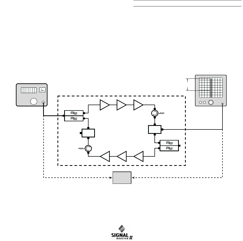
1) Measure the gain of the signal booster being
careful not to exceed the maximum input level.
Figure 8 shows this being done using a signal
generator and spectrum analyzer. Record the
measured values for each passband. We rec-
ommend that a 50 ohm load be connected to
the unused RF port on the bottom of the cabinet
during the gain test.
Signal
Generator
Zero
Reference
Spectrum
Analyzer
Gain
Sample
Sample
Test Port
Test Port
Figure 8: Measuring signal booster gain.
61-88-50-UserMan Page 18 of 29
Manual 7-9375-4 Page 13TX RX Systems Inc. 10/29/04
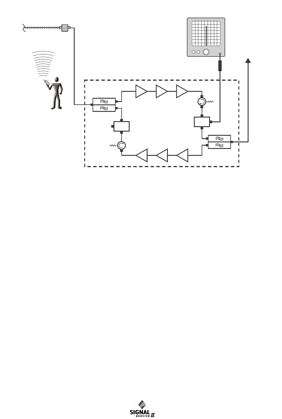
2) The spectrum analyzer is connected to the -30
dB signal sampler port following the final output
amp. This port will allow the observation of the
amplifier output at a considerably reduced out-
put level. This decoupling value (-30 dB) needs
to be added to any measured signal value in
order to arrive at the actual signal level.
3) With a spectrum analyzer connected to the sig-
nal sampler port (see Figure 9), have person-
nel with handheld radios move to several
predetermined points and key their radios.
Record the level of these signals as observed
on the analyzer and also record the location of
the person transmitting. In this way, a map of
the systems performance can be generated.
4) For signals coming from a fixed antenna or sta-
tion, record the level of all the desired incoming
signals for future reference.
MAINTENANCE AND REPAIR
Signal boosters manufactured by TX RX Systems,
Inc. can perform for years with little maintenance
and repair. However, if the amplifiers are subjected
to excessively high signal levels, power surges or
lightning strikes, failures may occur. The following
procedures may be followed for detecting a mal-
functioning unit or as part of a periodic mainte-
nance program.
1) The heatsink area should be cleared of dust
and debris.
2) Inspect the unit to see that the two power sup-
ply LED DC indicators are lit (remove any dust
or debris that may obscure the LEDs). This will
verify that DC power is flowing properly. Check
all hardware for tightness.
3) Compare system performance to initial perfor-
mance levels measured when the system was
first installed. The lack of signal can be traced to
a malfunctioning amplifier by progressive signal
monitoring from the output (far end) to the input
end of the system noting the area where the
Boosted
RF Signal
Signal Distribution System
Spectrum
Analyzer
10 dB Pad
Sample
Sample
Test Port
Test Port
Figure 9: Methodology for doing a performance survey of the signal distribution system.
61-88-50-UserMan Page 19 of 29
Manual 7-9375-4 Page 14TX RX Systems Inc. 10/29/04
signal returns to normal level. The next amplifier
toward the output end of the system will proba-
bly be the one that failed.
or
Measure the gain at any convenient frequency
in the working frequency band to verify that the
performance is still within specifications.
Power Amplifier Replacement
The SB II power amplifiers are field replaceable.
Follow the steps listed below in sequential order.
The required tools are a #1 Phillips screwdriver
and a 5/16” open-ended wrench.
Note: Power to the SB II cabinet must
be turned OFF during the power
amplifier replacement process.
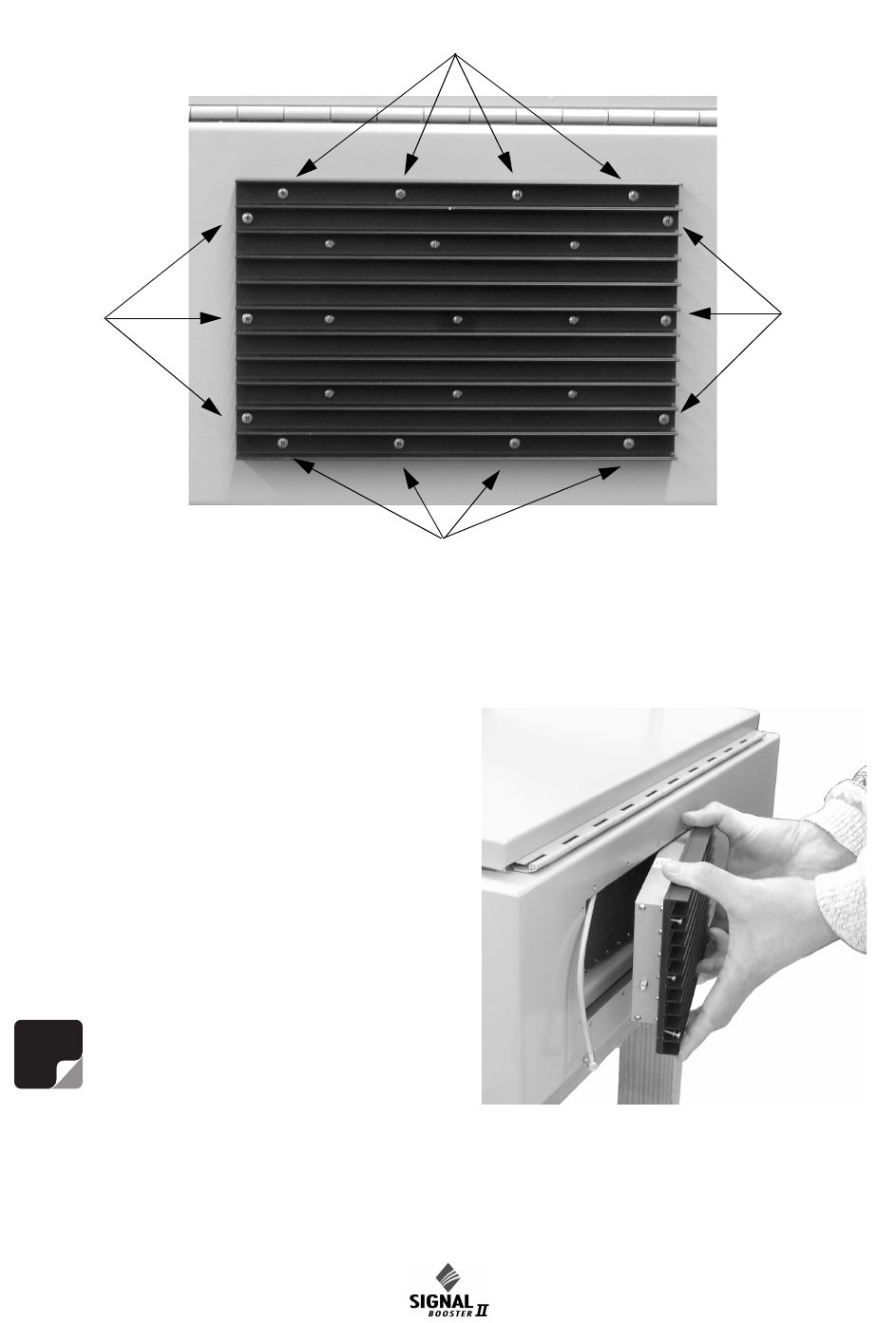
1) Remove the Phillips screws which hold the
amplifier into place, refer to Figure 10. The nuts
holding the screws are pressed into the cabinet
NOTE
Figure 10: Remove 14 mounting screws to detach amplifier assembly from cabinet.
Remove Screws
Remove Screws
Remove
Screws
Remove
Screws
Figure 11: Slide amplifier towards bottom of cabi-
net to remove upper cable.
61-88-50-UserMan Page 20 of 29
Manual 7-9375-4 Page 15TX RX Systems Inc. 10/29/04
and will remain in place when the screws are
removed.
2) Slide the amplifier towards the bottom of the
cabinet as far as it will go. This will allow the top
RF connector to clear the opening. Tilt the top
of the amplifier outwards and remove the top
RF cable at the SMA connector using the 5/16”
wrench. See Figure 11.
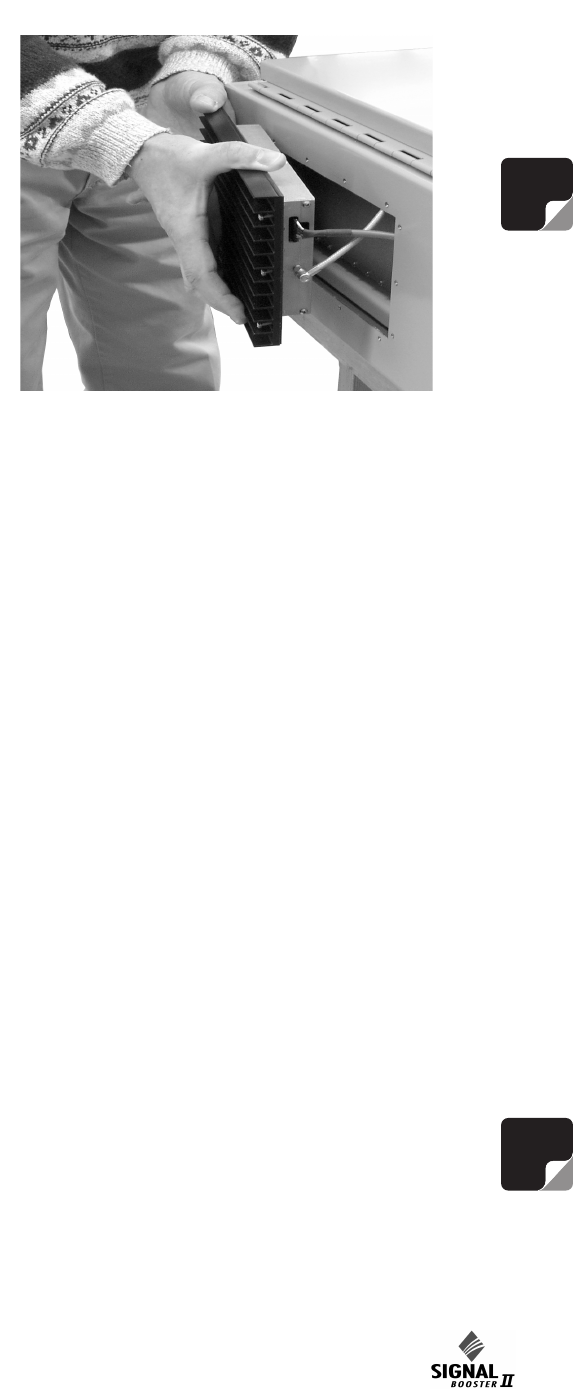
3) Slide the amplifier assembly towards the top of
the cabinet as far as it will go. This will allow the
bottom RF connector and grey control cable to
clear the opening. Tilt the bottom of the ampli-
fier outwards and remove the bottom RF cable
at the SMA connector and the grey control
cable. To remove the grey cable from the socket
on the amplifier it is necessary to squeeze the
top and bottom of the connector together to
release a hold down tab. When properly
squeezed the grey cable will disconnect easily
from the amplifier. Refer to Figure 12.
4) To replace the amplifier assembly repeat steps
1 through 3 in reverse order. When replacing
the RF cables do not overtighten the SMA con-
nectors. They should be tightened just slightly
more than hand tight or to the specification of 7
in/lbs. The replacement amplifier comes with an
attached gasket which must press up against
the outside of the cabinet firmly and squarely in
order to provide a correct moisture seal.
Module Replacement
The SB II modules are field replaceable. Follow the
steps listed below in sequential order. The required
tools are a #1 Phillips screwdriver. Two thumb
screws hold each module into place.
Note: Power to the SB II cabinet must
be turned OFF during the module
replacement process except for the
amplifier modules which are “HOT”
switchable.
1) Loosen the two thumb screws which hold the
module into place. Phillips screws are incorpo-
rated into the thumbscrews and they made
need to be loosened first.
2) Grasping the two loosened thumb screws pull
the module straight out of the card cage.
3) To install the replacement module place the
module into the guide-rails of the slot and press
down firmly into place. Each type of module is
keyed uniquely to fit in only one slot within the
card cage. Once the card is seated into place
properly tighten the thumb screws.
The SB II low level and mid level amplifier stages
are field replaceable by simply removing the mod-
ule and plugging in a replacement. These modules
are HOT switchable meaning they can be swapped
without powering down the system. RF cables
attached to the modules must be removed (5/16”
wrench) prior to swapping the modules and must
be re-attached after the new module is in place.
when replacing the RF cables do not overtighten
the SMA connectors. They should be tightened just
slightly more than hand tight or to the specification
of 7 in/lbs.
Modules can be swapped between the uplink and
downlink branches for troubleshooting purposes. If
a problem exists in one branch and the problem
moves to the other branch when modules are
swapped around this indicates a defective module.
Note: After an amplifier module is
replaced use the Calibrate Currents
software function to properly set the
amplifiers alarm trip point, see page 9.
Due to slight differences in component
tolerances the trip point must be reset for any new
amplifier assemblies introduced into the system.
NOTE
NOTE
Figure 12: Slide amplifier towards top of cabinet to
remove lower cables.
61-88-50-UserMan Page 21 of 29
Manual 7-9375-4 Page 16TX RX Systems Inc. 10/29/04
Display/User Interface Assembly Replacement
The SB II Display/User Interface assembly is field
replaceable. Follow the steps listed below in
sequential order. No tools are required.
Note: Power to the SB II cabinet must
be turned OFF during the display/user
interface replacement process.
1) Loosen the two thumb-nuts which hold the dis-
play/user interface assembly to the card cage.
2) Gently tilt only the top of the assembly up from
the card cage. Keep the bottom of the assembly
in place. The bottom mounting plate (part of the
card cage) has an overhang on it to support the
display/user interface board. If the assembly is
lifted straight out the overhang it could possibly
damage the interface circuit board.
3) With the display/user interface board standing
up straight gently move it upwards while lifting it
out about an inch or two. This should allow the
overhang to clear the interface circuit board
without damage.
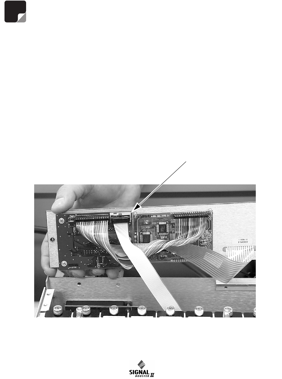
4) Remove the ribbon cable that connects the dis-
play/user interface assembly to the card cage,
see Figure 13.
5) To replace the display/user interface assembly
repeat steps 1 through 4 in reverse order.
Power Supply Replacement
The SB II power supply assembly is field replace-
able. Follow the steps listed below in sequential
order. The required tools are a #1 Phillips screw-
driver.
1) Turn off AC power at the junction box.
2) Disconnect the 3 conductor cable that brings
AC power to the supply from the junction box.
NOTE
Figure 13: Disconnecting the display/user interface assembly from the card cage.
Disconnect
ribbon cable
here
61-88-50-UserMan Page 22 of 29

Manual 7-9375-4 Page 17TX RX Systems Inc. 10/29/04
3) Disconnect the red and black leads from the
power supply that connect to the card cage.
4) Remove the Phillips screws that hold the power
supply mount bracket to the back plate and
remove the assembly from the cabinet.
5) Reverse steps 4 through 2 to install the replace-
ment power supply.
Filter Replacement
The filter assemblies are field replaceable. Follow
the steps listed below in sequential order. The
required tools are a #1 Phillips screwdriver with an
extended shaft to reach down far enough into the
unit to loosen the mounting screws.
Note: Power to the SB II cabinet must
be turned OFF during the filter
replacement process.
1) All RF cables attached to the assembly must be
removed (5/16” wrench).
2) Remove the Phillips screws that hold the
assembly mount brackets to the back plate and
remove the assembly from the cabinet.
3) Reverse steps 2 and 1 to install the replace-
ment filter. When replacing the RF cables do
not overtighten the SMA connectors. They
should be tightened just slightly more than hand
tight or to the specification of 7 in/lbs.
Card Cage Replacement
To replace the card cage follow the steps listed
below in sequential order. The required tools are a
#1 Phillips screwdriver with an extended shaft to
reach down far enough into the unit to loosen the
mounting screws.
Note: Power to the SB II cabinet must
be turned OFF during the card cage
replacement process.
1) Disconnect the display/user interface assembly.
2) Disconnect 4 cables at the backplane of the
card cage which are assessable with the dis-
play/user interface board out of the way.
3) Remove the row of Phillips screws which hold
the card cage to the back plate. There is a row
of screws at the top and bottom of the cage.
4) To install a replacement cage perform steps 3
through 1 in reverse order.
RECOMMENDED SPARES
It is recommended that one spare of each of the
following assemblies be kept on hand for emer-
gency repair purposes; Power Supply 8-19938,
Uplink Power Amplifier 3-19787, Downlink Power
Amplifier 3-20028, Mid Level Amplifier Card 3-
19576, Low Level Amplifier Card 3-19575, Low
Gain Amplifier Card 3-20294, Attenuator Card 3-
20208, Power Distribution Card 3-19833, Controller
Card 3-19832, and the Display/User Interface
Assembly 3-19831.
NOTE
NOTE
61-88-50-UserMan Page 23 of 29
Manual 7-9375-4 Page 18TX RX Systems Inc. 10/29/04
Model 61-88-50 Signal Booster Specifications
Part Number: 61-88-50-A06-G1 61-88-50-B06-G1 61-88-50-C06-G1
Electrical
Frequency Range: 896 - 941 MHz 896 - 941 MHz 896 - 941 MHz
FCC Identification Number: EZZ5P618850 EZZ5PI618850 EZZ5PI618850
Industry Canada Identification Number 1940A-PI618850 1940A-PI618850 1940A-PI618850
Number of Passbands: 2 2 2
Passband Frequencies: 896-902 / 935-941 MHz 896-902 / 935-941 MHz 896-902 / 935-941 MHz
Minimum Passband Separation: 45 MHz 45 MHz 45 MHz
Pass Bandwidth: 6 MHz 6 MHz 6 MHz
Maximum RF Power Output/Passband*: +35 dBm (3 Watts) +35 dBm (3 Watts) +35 dBm (3 Watts)
Gain: +80 dB +60 dB +45 dB
Guardband: 33 MHz 33 MHz 33 MHz
Output Level Control Range**: 60 dB 60 dB 60 dB
System Noise Figure at Maximum Gain: 3.5 dB maximum 6.5 dB maximum 6.5 dB maximum
Third Order Output Intercept Point: +55 dBm +55 dBm +55 dBm
Primary Supply Voltage: 100-240 VAC; 50-60 Hz 100-240 VAC; 50-60 Hz 100-240 VAC; 50-60 Hz
Automatic Battery Backup Option: +24 to +30 VDC +24 to +30 VDC +24 to +30 VDC
Mechanical
Height: 24" 24" 24"
Width: 24" 24" 24"
Depth: 8" 8" 8"
Weight 85 lbs. 85 lbs. 85 lbs.
Housing Type: Painted Steel Painted Steel Painted Steel
Enclosure Type: NEMA 4 Standard NEMA 4 Standard NEMA 4 Standard
* Maximum total power
** Output control range at maximum gain setting
Table 3, Signal Booster ii specifications
61-88-50-UserMan Page 24 of 29

Manual 7-9375-4 Page 19TX RX Systems Inc. 10/29/04
61-88-50-UserMan Page 25 of 29

Manual 7-9375-4 Page 20TX RX Systems Inc. 10/29/04
61-88-50-UserMan Page 26 of 29

Manual 7-9375-4 Page 21TX RX Systems Inc. 10/29/04
61-88-50-UserMan Page 27 of 29

Manual 7-9375-4 Page 22TX RX Systems Inc. 10/29/04
61-88-50-UserMan Page 28 of 29
Manual 7-9375-4 Page 23TX RX Systems Inc. 10/29/04
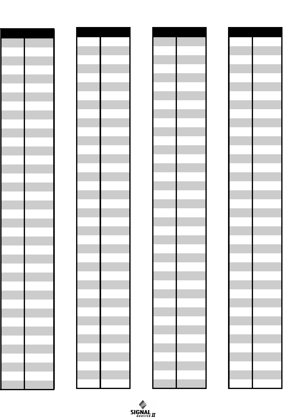
CELCIUS FARENHEIT
105 221.0
104 219.2
103 217.4
102 215.6
101 213.8
100 212.0
99 210.2
98 208.4
97 206.6
96 204.8
95 203.0
94 201.2
93 199.4
92 197.6
91 195.8
90 194.0
89 192.2
88 190.4
87 188.6
86 186.8
85 185.0
84 183.2
83 181.4
82 179.6
81 177.8
80 176.0
79 174.2
78 172.4
77 170.6
76 168.8
75 167.0
74 165.2
73 163.4
72 161.6
71 159.8
70 158.0
69 156.2
68 154.4
67 152.6
66 150.8
65 149.0
64 147.2
63 145.4
62 143.6
61 141.8
60 140.0
59 138.2
58 136.4
57 134.6
56 132.8
55 131.0
54 129.2
53 127.4
52 125.6
51 123.8
50 122.0
49 120.2
48 118.4
47 116.6
46 114.8
45 113.0
44 111.2
43 109.4
42 107.6
41 105.8
40 104.0
39 102.2
38 100.4
37 98.6
36 96.8
35 95.0
34 93.2
33 91.4
32 89.6
31 87.8
30 86.0
29 84.2
28 82.4
CELCIUS FARENHEIT
27 80.6
26 78.8
25 77.0
24 75.2
23 73.4
22 71.6
21 69.8
20 68.0
19 66.2
18 64.4
17 62.6
16 60.8
15 59.0
14 57.2
13 55.4
12 53.6
11 51.8
10 50.0
948.2
846.4
744.6
642.8
541.0
439.2
337.4
235.6
133.8
032.0
-1 30.2
-2 28.4
-3 26.6
-4 24.8
-5 23.0
-6 21.2
-7 19.4
-8 17.6
-9 15.8
-10 14.0
-11 12.2
CELCIUS FARENHEIT
-12 10.4
-13 8.6
-14 6.8
-15 5.0
-16 3.2
-17 1.4
-18 -0.4
-19 -2.2
-20 -4.0
-21 -5.8
-22 -7.6
-23 -9.4
-24 -11.2
-25 -13.0
-26 -14.8
-27 -16.6
-28 -18.4
-29 -20.2
-30 -22.0
-31 -23.8
-32 -25.6
-33 -27.4
-34 -29.2
-35 -31.0
-36 -32.8
-37 -34.6
-38 -36.4
-39 -38.2
-40 -40.0
-41 -41.8
-42 -43.6
-43 -45.4
-44 -47.2
-45 -49.0
-46 -50.8
-47 -52.6
-48 -54.4
-49 -56.2
-50 -58.0
CELCIUS FARENHEIT
CELCIUS TO FARENHEIT CONVERSION TABLE
61-88-50-UserMan Page 29 of 29