Bird Technologies Group 61170 Channelized Signal Booster User Manual
Bird Technologies Group Channelized Signal Booster
user manual

TX RX Systems Inc. 8625 Industrial Parkway, Angola, NY 14006 Tel: 716-549-4700 Fax: 716-549-4772 sales@txrx.com www.txrx.com
Installation and Operation Manual for
Channelized Signal Booster
Model 611-70
Manual Part Number
7-9469

Warranty
This warranty applies for one year from shipping date.
TX RX Systems Inc. warrants its products to be free from defect in material and workmanship at the time of shipment.
Our obligation under warranty is limited to replacement or repair, at our option, of any such products that shall have
been defective at the time of manufacture. TX RX Systems Inc. reserves the right to replace with merchandise of
equal performance although not identical in every way to that originally sold. TX RX Systems Inc. is not liable for dam-
age caused by lightning or other natural disasters. No product will be accepted for repair or replacement without our
prior written approval. The purchaser must prepay all shipping charges on returned products. TX RX Systems Inc.
shall in no event be liable for consequential damages, installation costs or expense of any nature resulting from the
purchase or use of products, whether or not they are used in accordance with instructions. This warranty is in lieu of all
other warranties, either expressed or implied, including any implied warranty or merchantability of fitness. No repre-
sentative is authorized to assume for TX RX Systems Inc. any other liability or warranty than set forth above in con-
nection with our products or services.
TERMS AND CONDITIONS OF SALE
PRICES AND TERMS:
Prices are FOB seller’s plant in Angola, NY domestic packaging only, and are subject to change without notice. Fed-
eral, State and local sales or excise taxes are not included in prices. When Net 30 terms are applicable, payment is
due within 30 days of invoice date. All orders are subject to a $100.00 net minimum.
QUOTATIONS:
Only written quotations are valid.
ACCEPTANCE OF ORDERS:
Acceptance of orders is valid only when so acknowledged in writing by the seller.
SHIPPING:
Unless otherwise agreed at the time the order is placed, seller reserves the right to make partial shipments for which
payment shall be made in accordance with seller’s stated terms. Shipments are made with transportation charges col-
lect unless otherwise specified by the buyer. Seller’s best judgement will be used in routing, except that buyer’s routing
is used where practicable. The seller is not responsible for selection of most economical or timeliest routing.
CLAIMS:
All claims for damage or loss in transit must be made promptly by the buyer against the carrier. All claims for shortages
must be made within 30 days after date of shipment of material from the seller’s plant.
SPECIFICATION CHANGES OR MODIFICATIONS:
All designs and specifications of seller’s products are subject to change without notice provided the changes or modifi-
cations do not affect performance.
RETURN MATERIAL:
Product or material may be returned for credit only after written authorization from the seller, as to which seller shall
have sole discretion. In the event of such authorization, credit given shall not exceed 80 percent of the original pur-
chase. In no case will Seller authorize return of material more than 90 days after shipment from Seller’s plant. Credit
for returned material is issued by the Seller only to the original purchaser.
ORDER CANCELLATION OR ALTERATION:
Cancellation or alteration of acknowledged orders by the buyer will be accepted only on terms that protect the seller
against loss.
NON WARRANTY REPAIRS AND RETURN WORK:
Consult seller’s plant for pricing. Buyer must prepay all transportation charges to seller’s plant. Standard shipping pol-
icy set forth above shall apply with respect to return shipment from TX RX Systems Inc. to buyer.
DISCLAIMER
Product part numbering in photographs and drawings is accurate at time of printing. Part number labels on TX RX
products supersede part numbers given within this manual. Information is subject to change without notice.
Bird Technologies Group TX RX Systems Inc.
Symbols Commonly Used
WARNING
ESD Electrostatic Discharge
Hot Surface
Electrical Shock Hazard
Important Information
CAUTION or ATTENTION
High Voltage
Heavy Lifting
Bird Technologies Group TX RX Systems Inc.
NOTE
Manual Part Number 7-9469
Copyright © 2009 TX RX Systems, Inc.
First Printing: March 2009
Version Number Version Date
1 03/30/09
1.1 06/10/09

For Class A Unintentional Radiators
This equipment has been tested and found to comply with the limits for a Class A digital device, pursuant
to Part 15 of the FCC rules. These limits are designed to provide resonable protection against harmful
interference when the equipment is operated in a commercial environment. This equipment generates,
uses, and can radiate radio frequency energy and, if not installed and used in accordance with the instruc-
tion manual, may cause harmful interference to radio communications. Operation of this equipment in a
residential area is likely to cause harmful interference in which the user will be required to correct the inter-
ference at his own expense.
WARNING: Changes or modifications which are not expressly approved by TXRX
Systems Inc. could void the user’s authority to operate the equipment.
ATTENTION: This device complies with Part 15 of the FCC rules. Operation is subject to the
following two conditions: (1) this device may not cause harmful interference and (2) this
device must accept any interference received, including interference that may cause undes-
ired operation.
Table of Contents Manual 7-9469-1.1 06/10/09
Table of Contents
Overview............................................................................................................... 1
Down / Up Conversion......................................................................................... 2
Unpacking ............................................................................................................ 2
Installation............................................................................................................ 2
Location ............................................................................................................. 2
Antenna Isolation ............................................................................................... 2
Required Equipment ......................................................................................... 2
Measurement Procedure .................................................................................. 3
Functional Block Diagram Description ............................................................. 4
Downlink / Uplink Input Signals ........................................................................... 4
Downlink / Uplink Output Signals ........................................................................ 4
Channel Module 3-22322 .................................................................................... 4
Operation.............................................................................................................. 6
Module LED’s ..................................................................................................... 6
RF Exposure ........................................................................................................ 6
Figures and Tables
Figure 1: The Down / Up Converter Process ....................................................... 1
Figure 2: Measuring Antenna Isolation................................................................. 3
Figure 3: Functional Block Diagram ..................................................................... 4
Figure 4A: Module housing Front View ................................................................ 5
Figure 4B: Module Housing rear View.................................................................. 5
Figure 5: Channel Module Block Diagram............................................................ 6
Table 1: Specifications .......................................................................................... 1
Table 2: Channel Module Indicator LED’s............................................................. 7

Table of Contents Manual 7-9469-1.1 06/10/09
Contact Information
Changes to this Manual
Bird Technologies Group TX RX Systems Inc.
Sales Support at 716-549-4700 extension 5043
Customer Service at 716-549-4700 extension 5044
Technical Publications at 716-549-4700 extension 5019
We have made every effort to ensure this manual is accurate. If you discover any
errors, or if you have suggestions for improving this manual, please send your
comments to our Angola, New York facility to the attention of the Technical Publications
Department. This manual may be periodically updated. When inquiring about updates to
this manual refer to the manual part number and revision number on the revision page
following the front cover.
TX RX Systems Inc. Manual 7-9469-1.1 06/10/09 Page 1
OVERVIEW
Signal boosters extend radio coverage into areas
where abrupt propagation losses prevent reliable
communication. The system receives an RF signal,
raises its power level, and couples it to an antenna
so that it can be re-radiated. The input signal may
be derived from a receiving antenna or a long run
of radiating coax.
The TXRX model 611-70 channelized signal
booster is designed to operate in the 450 to 470
MHz range. The system is based on a module
design with each module capable of handling one
uplink and one downlink channel simultaneously.
The size of the system can be tailored to the cus-
tomers needs by increasing or decreasing the
number of modules used. Each module is bi-direc-
tional with one downlink and one uplink signal
branch. Each of the two branches in a module are
independently tunable to their required pass fre-
quency via software interface.
The systems part number is used to describe the
configuration of the product. The first three digits
are always 611 and describe the channelized sig-
nal booster product group. The second group of
two digits describe the frequency range (450 to 470
MHz). The next two digit group describes the num-
ber of channel modules while the last letter
describes the mounting method used (the letter “A”
represents rack mounted). Specifications for the
611-70 family of channelized signal boosters are
listed in Table1.
Intermediate
Frequency
Signal
Processing
1st Mixer 2nd Mixer
RF OutRF In
Local
Oscillator
Figure 1: The down converter / up converter process.
Frequency Range 450 - 470 MHz
Number of Carriers
per Channel
1 Uplink
1 Downlink
Nominal Passband
Gain 120 dB
Channel Bandwidth
Standard 25 KHz;
can be programmed to
meet group delay require-
ments
(User Selectable)
Output Power
per Channel + 37 dBm ERP
Maximum Input Level -40 dBm
RF In/Out Impedance 50 Ohms
Alarms Form-C Contacts
Module LED’s
Power
90 - 250 VAC, 50/60 Hz
or
28 VDC (+/- 5%)
Operating Temperature
Range -30°C to +60°C
Table 1: Specifications
TX RX Systems Inc. Manual 7-9469-1.1 06/10/09 Page 2
Down / Up Conversion
A channelized signal booster has much in common
with a superheterodyne (superhet) receiver. The
incoming signal is converted to a lower frequency
so that single channel selectivity can be obtained.
It is then filtered. Unlike the superhet receiver how-
ever, the signal is not demodulated. Instead, it is
up-converted back to its original frequency where it
is further amplified to reach a useful power level.
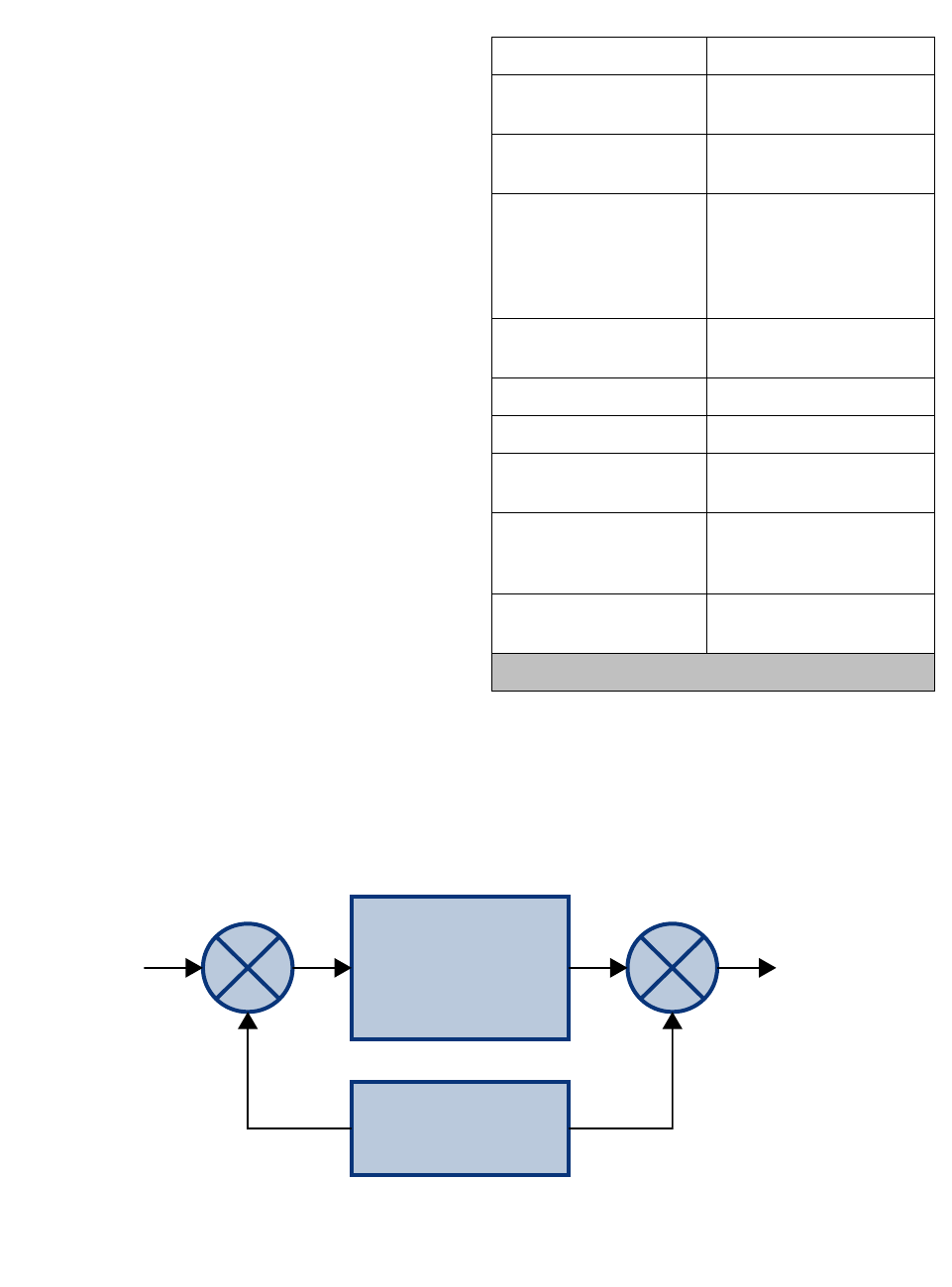
Figure 1 shows a simplified block diagram that
illustrates the down/up conversion principle. An
incoming signal at (Freq IN) is applied to the first
mixer along with a signal from a local oscillator
(Freq LO). A third signal at an intermediate fre-
quency (Freq IF) is produced as a result of the mix-
ing. The intermediate frequency is given by the
following relationship:
(1) Freq IF = Freq IN - Freq LO
The IF signal from the mixer then passes through
filtering with single channel bandwidth before being
amplified and passed on to the second mixer. The
second mixer also receives the same local oscilla-
tor signal (Freq LO). The result is a mixing product
frequency at the output of mixer 2. The output fre-
quency (Freq OUT) is given by the following rela-
tionship:
(2) Freq OUT = Freq IF + Freq LO
Substituting equation (1) for the “Freq IF” term in
equation (2) allows the “Freq LO” terms to be can-
celed yielding:
(3) Freq Out = Freq IN
The implication of equation (3) is that the frequency
stability of the signal that is processed by this type
of signal booster is not affected by the frequency
stability of the signal booster itself. Frequency sta-
bility depends only on the stability of the signal
source producing the signal to be boosted. A shift
in the LO frequency of the signal booster will only
cause a shift in the IF frequency with a possible
loss of signal amplitude but no change in the out-
put signal frequency.
UNPACKING
It is important to report any visible damage to the
carrier immediately. It is the customers responsibil-
ity to file damage claims with the carrier within a
short period of time (1 to 5 days). Care should be
taken when removing the unit from the packing box
to avoid damage to the unit.
INSTALLATION
The following sub-sections of the manual discuss
general considerations for installing the booster. All
work should be performed by qualified personnel
and in accordance with local codes.
Location
The layout of the signal distribution system will be
the prime factor in determining the mounting loca-
tion of this unit. However, safety and serviceability
are also key considerations. The unit should be
located where it can not be tampered with by the
general public, yet is easily accessible to service
personnel. Also, consider the weight of the unit and
the possibility for injury if it should become
detached from its mounting for any reason.
The booster needs to be installed such that there
can be unobstructed air flow over and around the
subassemblies. The various subassemblies will
stay warm to the touch during normal operation so
in the interest of equipment longevity, avoid loca-
tions that carry hot exhaust air or are continually
hot.
Antenna Isolation
Antenna isolation between uplink and downlink
should be measured before connecting the signal
booster to the antenna system. This step is neces-
sary to insure that no conditions exist that could
possibly damage the signal booster and should not
be skipped for even the most thoroughly designed
system.
Just like the feedback squeal that can occur when
the microphone and speaker get too close together
in a public address system, a signal booster can
start to self oscillate. This can occur when the iso-
lation between the Uplink and Downlink antennas
does not exceed the signal boosters gain by at
least 15 dB. Oscillation will reduce the effective-
ness of the system and may possibly damage
amplifier stages. Isolation values are relatively
easy to measure with a spectrum analyzer and sig-
nal generator.
REQUIRED EQUIPMENT
The following equipment is required in order to per-
form the antenna isolation measurements.
TX RX Systems Inc. Manual 7-9469-1.1 06/10/09 Page 3
1) Signal generator for the frequencies of interest
capable of a 0 dBm output level. Modulation is
not necessary.
2) Spectrum analyzer that covers the frequencies
of interest and is capable of observing signal
levels down to -100 dBm or better.
3) Double shielded coaxial test cables made from
RG142, RG55 or RG223 coaxial cable.
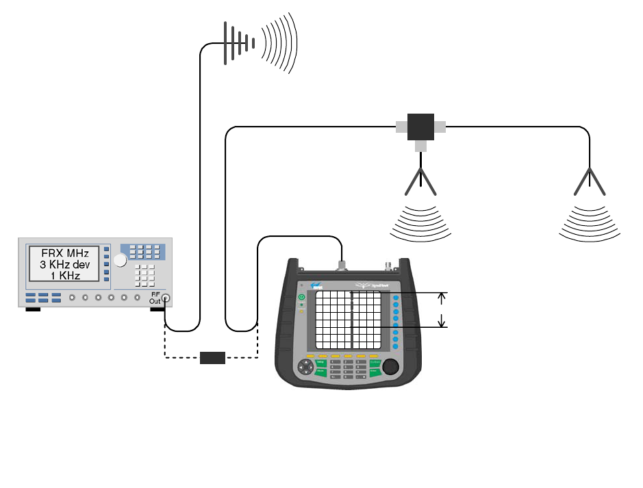
MEASUREMENT PROCEDURE
To measure the antenna isolation perform the fol-
lowing in a step-by-step fashion.
1) Set the signal generator for a 0 dBm output level
at the center frequency of the boosters pass-
band.
2) Set the spectrum analyzer for the same center
frequency and a sweep width equal to or just
slightly greater than the passband chosen ear-
lier in step 1.
3) Temporarily connect the test leads of the signal
generator and spectrum analyzer together
using a female barrel connector, see Figure 2.
Observe the signal on the analyzer and adjust
the input attenuator of the spectrum analyzer
for a signal level that just reaches the 0 dBm
level at the top of the graticule.
4) Referring to Figure 2, connect the generator test
lead to one side of the antenna system and the
spectrum analyzer to the other then observe the
signal level. The difference between the
observed level and 0 dBm is the isolation
between the sections. If the signal is too weak
to observe, the spectrum analyzer’s bandwidth
may have to be narrowed and it’s input attenua-
tion reduced. The isolation value measured
should exceed the signal booster’s gain figure
by at least 15 dB.
5) Repeat step 4 again with the signal generator
set at the passband edges in order to see if the
Signal Generator
External
Antenna
(YAGI)
Spectrum Analyzer
Isolation (dB)
Zero Loss
Reference
Internal
Signal Distribution
System
(Omni-directional
Antennas)
Figure 2: Typical test equipment interconnection for measuring antenna isolation.
TX RX Systems Inc. Manual 7-9469-1.1 06/10/09 Page 4
isolation is remaining relatively constant over
the complete width of the passband.
6) Repeat the isolation measurements if necessary
at other system passbands to determine the
overall minimum isolation value for the system.
Physical modification of the antenna system
maybe required in order to reach an acceptable
minimum value.
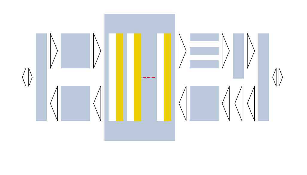
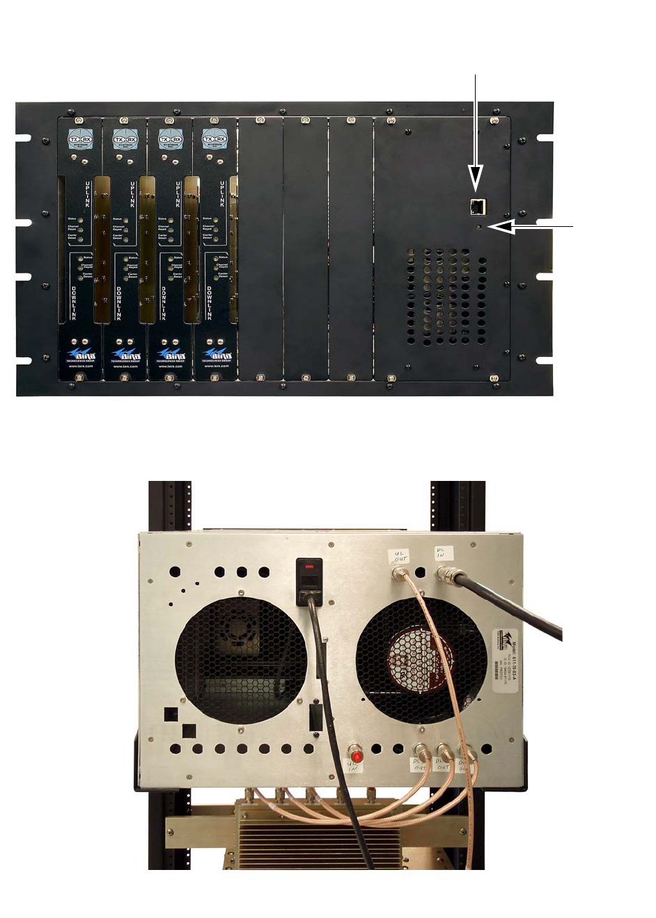
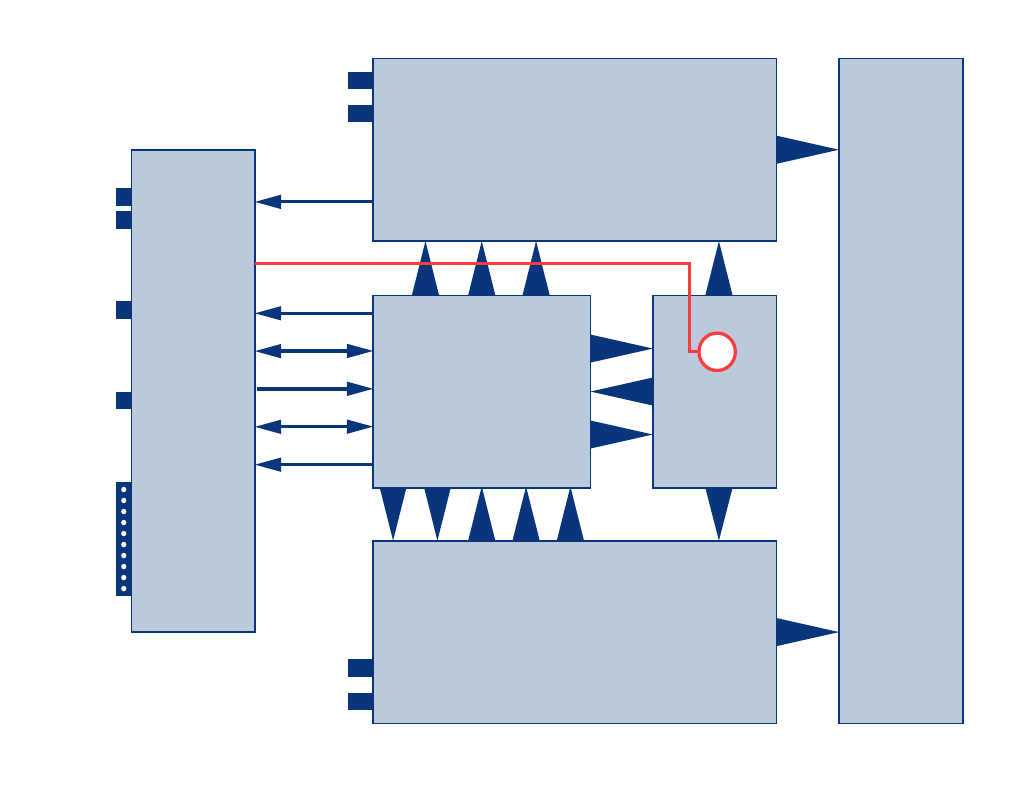
FUNCTIONAL BLOCK DIAGRAM DISCUSSION
Figure 3 is the functional block diagram of the
channelized signal booster model 611-70. Figure
4A and 4B show the front and rear views of the
module housing.
Downlink / Uplink Input Signals
Downlink and Uplink input signals are applied to a
distribution amplifier 3-22340. This is an ultra-low
noise high linearity amplifier with a gain of 18.9 dB.
Refer to schematic 3-22341. Following the distribu-
tion amp is a 6-way power divider which is used to
distribute the signal to individual channel modules.
Downlink signals are applied to the down converter
board of a downlink branch while uplink signals are
applied to the down converter board of an uplink
branch. Any unused output ports of the 6-Way
should be terminated with a 50 ohm load. Signal
processing within the channel module is discussed
in the Channel module section below.
Downlink / Uplink Output Signals
Downlink signals leave the channel module at the
DL OUT connector and are applied to a power
amplifier 8-22290 which has a typical gain of 35
dB. After amplification, signals from multiple mod-
ules are combined by a Hybrid Combiner 3-18317-
1 and fed into combline filtering before being
applied to an antenna. Uplink output signals leave
the channel module at the UL OUT connector and
are applied to an active combiner 3-22319. The
active combiner amplifies and combines signals
from multiple modules. Following the active com-
biner is combline filtering.
Channel Module 3-22322
The channel modules are bi-directional with each
module containing one downlink branch and one
uplink branch. The branches are functionally identi-
cal because the same set of circuit boards are
used in each branch. The uplink and downlink
branches can work on different frequencies within
the modules passband (450 to 470 MHz) but for
either branch the input and output signals will be
the same frequency. Figure 5 is the block diagram
of the channel module.
Active
Receiver
Multicoupler
Active
Channel
Combiner
(one amp
per input)
Duplexer/Filter
Duplexer/Filter
To
Donor
Antenna
Channel Module
20W PA
To
Coverage
Antenna
System
Channel Module - Downlink
Channel Module - Uplink
Channel Module - Downlink
Channel Module - Uplink
Channel Module - Downlink
Channel Module - Uplink
Active
Receiver
Multicoupler
20W PA
20W PA
Hybrid Combiner
Figure 3: Functional block diagram of the channelized signal booster.
TX RX Systems Inc. Manual 7-9469-1.1 06/10/09 Page 5
Figure 4A: Module housing front view.
User
Interface
Connector
Power ON
LED
Indicator
Figure 4B: Module housing rear view.
TX RX Systems Inc. Manual 7-9469-1.1 06/10/09 Page 6
Each branch consists of four boards; Digital, Local
Oscillator, Down Converter, and Up Converter. RF
signals enter the branch at the down converter
board where they are filtered, amplified, and con-
verted into a 70 MHz intermediate frequency. The
digital board digitizes the IF signal with an ADC.
The digitized samples are applied to a programma-
ble gated array for digital filtering. The filtered sig-
nals from the array are converted back into analog
by a DAC and output to the up converter board.
The up converter board converts the IF back into
the original UHF signal and outputs it from the
module. The Local Oscillator board generates the
reference signals for mixing and sampling. The
mixing frequency can range from 380 to 400 MHz
and is determined by the user via interface with the
micro controller on the digital board.
OPERATION
Power is applied to the unit by plugging in the AC
power cord. There is a Power-ON LED located on
the front of the unit (near the computer interface
connector) which will illuminate when power is
applied.
Module LED’s
There are six LED indicators on the front of each
channel module, 3 for the uplink branch and 3 for
the downlink branch. The function of indicator
LED’s are listed in Table 2.
RF EXPOSURE
To comply with FCC RF exposure compliance
requirements, a separation distance of at least 100
cm must be maintained between the antenna of
this device and all persons. This device must not
be co-located or operating in conjunction with any
other antenna or transmitter.
10M Ref
Alarm
Logic
Form 'C'
Squelch
RF Out (DL)
RF In (UL)
Out
10 MHz
+28 VDC
I2C
Form
"C"
Contacts
In
RF Out (UL)
RF In (DL)
LED
Connect
(UL)
LED
Connect
(DL)
LEDs
(3)
5.5V
5.5V
5.5V
DAC Out
(2)
LO
LO
Attn Cnl
(4)
ADC
in (2)
Vocm AGC
Cnl (2)
Freq Cnl
(3)
56M (3)
Up Converter Board
3-22302
Interface
Board
3-22315
LED
Board
3-22295
Down Converter Board
3-22308
LO Board
3-22312
Digital Board
3-22310
10M
28V
I2C
Thru Wall Cable
Figure 5: Channel Module block diagram.

TX RX Systems Inc. Manual 7-9469-1.1 06/10/09 Page 7
Status LED
Green (flashing fast) Unit Identification (for several seconds only on command from User Interface)
Orange (slow flash) Unprogrammed unit (no settings set)
Off Unit disabled (no output from module)
Red (slow flash) External reference selected but is absent or not locked
Red (solid ON) Alarm of some kind (current or temp out of limits, LO not locked, filter not set)
Green (solid ON) all is OK
Channel Keyed
Slow Flash Unprogrammed unit (no settings set)
ON
Unit will transmit signal
if CTCSS and DCS disabled then signal present on input above carrier squelch threshold
Else if one is enabled then it means that the selected CTCSS or DCS code has been detected
OFF Unit will not transmit signal
Carrier Detect
Slow Flash Unprogrammed Unit (no settings set)
ON Signal present on input above carrier squelch threshold
OFF No signal present on input above carrier squelch threshold
Table 2: Channel Module Indicator LED’s

TX RX Systems Inc. Manual 7-9469-1.1 06/10/09 Page 8
TX RX Systems Inc. 8625 Industrial Parkway, Angola, NY 14006 Tel: 716-549-4700 Fax: 716-549-4772 sales@txrx.com www.txrx.com
SYSTEMS
INC.
SYSTEMS
INC.