4045B DDS Function Generator Manual
2014-04-30
: Bk 4045B Manual 4045B_manual en-us manuals s
Open the PDF directly: View PDF ![]() .
.
Page Count: 110 [warning: Documents this large are best viewed by clicking the View PDF Link!]
- 1
- 1
- 1
- 1
- 1
- 1
- 1
- 1
- 1
- 1
- 1
- 1
- 1
- 1
- 1
- 1
- 1
- 1
- 1
- 1
- 1
- 1
- 1
- 1
- 1
- 1
- 1
- 1
- 1
- 1
- 1
- 1
- 1
- 1
- 1
- 1
- 1
- 1
- 1
- 1
- 1
- 1
- 1
- 1
- 1
- 1
- 1
- 1
- 1
- 1
- 1
- 1
- 1
- 1
- 1
- 1
- 1
- 1
- 1
- 1
- 1
- 1 Introduction
- 2 Installation
- 3 Operating Instructions
- 4 Programming
Model: 4045B
Arbitrary Function
Generator
USER MANUAL

2

3
Safety Summary
The following safety precautions apply to both operating
and maintenance personnel and must be observed
during all phases of operation, service, and repair of this
instrument. Before applying power, follow the installation
instructions and become familiar with the operating
instructions for this instrument.
If this device is damaged or something is missing,
contact the place of purchase immediately.
This manual contains information and warnings that
must be followed to ensure safe operation as well as
maintain the meter in a safe condition.
GROUND THE INSTRUMENT
To minimize shock hazard, the instrument chassis and
cabinet must be connected to an electrical ground. This
instrument is grounded through the ground conductor of
the supplied, three-conductor ac power cable. The
power cable must be plugged into an approved three-
conductor electrical outlet. Do not alter the ground
connection. Without the protective ground connection,
all accessible conductive parts (including control knobs)
can render an electric shock. The power jack and
mating plug of the power cable must meet IEC safety
standards.
DO NOT OPERATE IN AN EXPLOSIVE
ATMOSPHERE
Do not operate the instrument in the presence of
flammable gases or fumes. Operation of any electrical
instrument in such an environment constitutes a definite
safety hazard.
KEEP AWAY FROM LIVE CIRCUITS
Instrument covers must not be removed by operating
personnel. Component replacement and internal

4
adjustments must be made by qualified maintenance
personnel. Disconnect the power cord before removing
the instrument covers and replacing components.
Under certain conditions, even with the power cable
removed, dangerous voltages may exist. To avoid
injuries, always disconnect power and discharge circuits
before touching them.
DO NOT SERVICE OR ADJUST ALONE
Do not attempt any internal service or adjustment unless
another person, capable of rendering first aid and
resuscitation, is present.
DO NOT SUBSTITUTE PARTS OR MODIFY THE
INSTRUMENT
Do not install substitute parts or perform any
unauthorized modifications to this instrument. Return
the instrument to B&K Precision for service and repair to
ensure that safety features are maintained.
WARNINGS AND CAUTIONS
WARNING and CAUTION statements, such as the
following examples, denote a hazard and appear
throughout this manual. Follow all instructions
contained in these statements.
A WARNING statement calls attention to an operating
procedure, practice, or condition, which, if not followed
correctly, could result in injury or death to personnel.
A CAUTION statement calls attention to an operating
procedure, practice, or condition, which, if not followed
correctly, could result in damage to or destruction of part
or all of the product.
WARNING:
Do not alter the ground connection. Without the
protective
ground connection, all accessible
conductive parts (including control knobs) can
render an electric shock. The power jack and mating
plug of the power cable meet IEC safety standards.

5
WARNING:
To avoid electrical shock hazard, disconnect power
cord before removing covers. Refer servicing to
qualified personnel.
CAUTION:
Before connecting the line cord to the AC mains,
check the rear panel AC line voltage indicator.
Applying a line voltage other than the indicated
voltage can destroy the AC line fuses. For continued
fire protection, replace fuses only with those of the
specified voltage and current ratings.
CAUTION:
This product uses components which can be
damaged by electro
-
static discharge (ESD). To avoid
damage, be sure to follow proper procedures for
handling, storing and transporting parts and
subassemblies which contain ESD
-
sensitive
components.

6
Compliance Statements
Disposal of Old Electrical & Electronic Equipment
(Applicable in the European
Union and other European countries with
separate collection systems)
This product is subject to
Directive 2002/96/EC of the
European
Parliament and the Council
of the European Union on
waste
electrical and electronic
equipment (WEEE) , and in
jurisdictions
adopting that Directive, is
marked as being put on the
market after August 13,
2005, and should not be
disposed of as unsorted
municipal waste. Please
utilize your local WEEE
collection
facilities in the disposition
of this product and
otherwise observe all
applicable requirements.
7
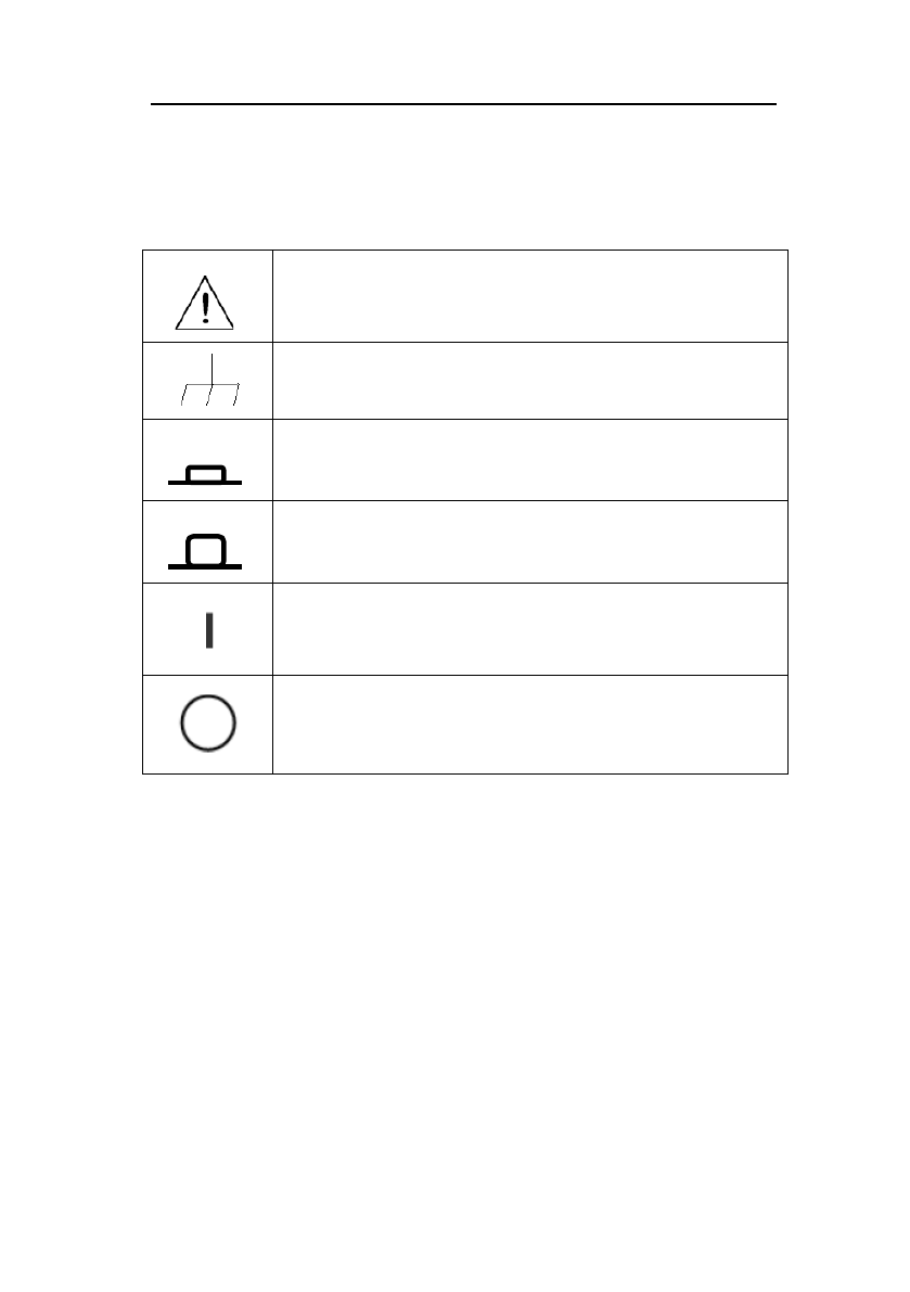
Safety Symbols
Refer to the user manual for warning
information to avoid hazard or personal
injury and prevent damage to instrument.
Chassis (earth ground) symbol.
On (Power). This is the In position of the
power switch when instrument is ON.
Off (Power). This is the Out position of
the power switch when instrument is OFF.
On (Supply). This is the AC mains
connect/disconnect switch at the back of
the instrument.
Off (Supply). This is the AC mains
connect/disconnect switch at the back of
the instrument.

8
CE Declaration of Conformity
The model 4045B meets the requirements of
2006/95/EC Low Voltage Directive and 2004/108/EC
Electromagnetic Compatibility Directive with the
following standards.
Low Voltage Directive
- EN61010
Safety requirements for electrical
equipment for measurement, control,
and laboratory use.
EMC Directive
- EN55011
For radiated and conducted emissions.
- EN55082
Electrical discharge immunity

9
1 INTRODUCTION .................... 12
1.1 Introduction ........................................... 12
1.2 Description ........................................... 12
1.3 Specifications ....................................... 13
2 INSTALLATION ..................... 18
2.1 Introduction ........................................... 18
2.2 Package Contents ................................ 18
2.3 Instrument Mounting ............................. 19
2.4 Power Requirements ............................ 19
2.5 Fuse Replacement................................ 20
2.6 Grounding Requirements ...................... 20
2.7 Signal Connections ............................... 21
3 OPERATING INSTRUCTIONS
22
3.1 General Description .............................. 22
3.2 Display Window .................................... 24
3.3 Front Panel Controls ............................. 24
3.4 Connectors ........................................... 24
3.5 Output Connections .............................. 25
3.6 MENU Keys .......................................... 27
3.6.1 WAVEFORM Keys ....................... 27
3.6.2 MODE Key .................................... 29
3.6.3 UTILITY Key ................................. 32

10
3.6.4 SWEEP Key ................................. 34
3.6.5 MODULATION Key ...................... 36
3.7 ON Key .................................................48
3.8 Cursor Keys ..........................................49
3.9 Rotary Input Knob .................................49
3.10 Power-On Settings ..............................49
3.11 Memory ...............................................50
3.12 Displaying Errors ................................51
3.13 Quick Start ..........................................52
3.13.1 Selecting a Standard Waveform
................................................................ 52
3.13.2 Setting the Output ................... 52
3.13.3 Using Voltage Offset ............... 53
3.13.4 Storing and Recalling a
Waveform Generator Setup .................. 53
4 PROGRAMMING ................... 60
4.1 Overview ..............................................60
4.1.1 Connecting to USB (Virtual COM)
Interface.................................................. 60
4.1.2 USB (Virtual COM) Settings ....... 66
4.2 Device States .......................................67
4.2.1 Local State (LOCS) ..................... 67
4.2.2 Remote State (REMS) ................. 67
4.3 Message Exchange Protocol ...............67

11
4.3.1 The Input Buffer .......................... 68
4.3.2 The Output Queue ....................... 68
4.3.3 Response Messages ................... 68
4.4 Instrument Identification ....................... 69
4.5 Instrument Reset ................................. 69
4.6 Command Syntax ............................... 69
4.6.1 General Command Structure ..... 69
4.7 Status Reporting .................................. 74
4.7.1 The Error Queue .......................... 74
4.7.2 Error Codes ................................. 75
4.8 COMMON COMMANDS ...................... 80
4.8.1 System Data Commands ............ 80
4.8.2 Internal Operation Commands ... 80
4.8.3 Device Trigger Commands ......... 81
4.8.4 Stored Settings Commands ....... 81
4.9 INSTRUMENT CONTROL COMMANDS
.................................................................... 82
4.9.1 Default Subsystem ...................... 83
4.9.2 Arbitrary Subsystem ................... 99

12
1 Introduction
1.1 Introduction
This manual contains information required to operate the
B&K Precision model 4045B Arbitrary Function
Generator. This section covers the instrument’s general
description, specifications, and characteristics.
1.2 Description
The 4045B is a versatile high performance function
generators with arbitrary capabilities. Implemented using
a DDS (direct digital synthesis) architecture, these
instruments generate stable and precise sine, square,
triangle and arbitrary waveforms. The unit also provides
linear and logarithmic sweep for users needing sweep
capability. An auxiliary TTL output at the generator’s set
frequency is available to synchronize external devices.
The instrument can also be remotely operated via the
USB interface and is SCPI compatible.

13
1.3 Specifications
Model
4045B
Frequency Characteristics
Sine
0.01 Hz – 20 MHz
Square
0.01 Hz – 20 MHz
Triangle
0.01 Hz – 2 MHz
Accuracy
0.001% (10 ppm)
at < 500 Hz: 0.001% + 0.006 Hz
Resolution
6 digits or 10 mHz
Output Characteristics
Amplitude Range
10 mV
p-p
to 10 V
p-p
(into 50 Ω)
20 mVp-p to 20 Vp-p (open circuit)
Resolution
3 digits (1000 counts)
Amplitude Accuracy
± 2 % ± 20 mV of programmed
output from 1.01 V – 10 V
Flatness
± 0.5 dB to 1 MHz
± 1 dB to 20 MHz
Offset Range
- 4.99 V to 4.99 V (into 50 Ω)
Offset Resolution
10 mV, 3 digits
Offset Accuracy
± 2 % ± 10 mV (into 50 Ω)
Output Impedance
50 Ω ± 2 %
Output Protection
Protected against short circuit or
accidental voltage practically
available in electronic
laboratories, applied to the main
output connector
Waveform Characteristics
**Harmonic
Distortion
0 – 1 MHz, < - 60 dBc
1 MHz – 5 MHz, < -50 dBc
5 MHz – 12 MHz , < -45 dBc
12 MHz – 20 MHz, < -50 dBc

14
Square Rise/Fall
Time
< 20 ns (10% to 90% at full
amplitude into 50 Ω)
Variable Duty
Cycle/Symmetry
Square: 20% to 80 %, up to 2
MHz
Triangle: 1 % to 99 % in 1%
steps, up to 200 kHz
Symmetry Accuracy
at 50%
± 1 %
Arbitrary Waveform Characteristics
Sampling Rate
20 ns to 50 s
Vertical Resolution
12 bits
Accuracy
0.001%
Resolution
4 digits
Waveform Length
2 – 1k points
Operating Modes
Continuous
Output continuous at
programmed parameters
Triggered
Output quiescent until triggered
by an internal or external trigger,
at which time one waveform
cycle is generated to
programmed parameters.
Frequency of waveform cycle is
limited to 1 MHz.
Gate
Same as triggered mode, except
waveform is executed for the
duration of the gate signal. The
last cycle started is completed.
Burst
2 – 65535 cycles
Trigger Source
Trigger source may be internal,
external, or manual. Internal
trigger rate 0.1 Hz – 1 MHz (1μs

15
– 10 s)
Modulation Characteristics
Amplitude
Modulation
Internal
0.1 Hz – 20 kHz sine, square, or
triangle waveform
External
5 V
p-p
for 100% modulation, 10
kΩ input impedance
Frequency
Modulation
Internal
0.1 Hz – 20 kHz sine, square, or
triangle waveform
External
5 V
p-p
for 100% modulation, 10
kΩ input impedance
Sweep Characteristics
Sweep Shape
Linear or Logarithmic, up or
down
Sweep Time
10 ms to 100 s
Input and Output
Trigger IN
TTL compatible
Maximum rate 1 MHz
Minimum width > 50 ns
Input impedance 1 kΩ
Sync OUT
TTL pulse at programmed
frequency
50 Ω source impedance
Modulation IN
5 V
p-p
for 100% modulation
10 kΩ input impedance
DC to > 20 kHz minimum
bandwidth
Counter Characteristics
Range
50 Hz to 50 MHz
Resolution
Auto ranging, up to 8 digits

16
Accuracy
± 0.02 % ± 2 digits
Sensitivity
25 mVrms typical
General
Memory Storage
Store up to 20 instrument
settings
Arbitrary memory
1,000 points in flash memory
Power Requirements
100 V – 240 V AC ± 10% (90 V
– 264 VAC), 47 – 63 Hz
Max. Power
Consumption
< 30 VA
Operating
Temperature
0 °C – 50 °C
Storage Temperature
-10 °C – 70 °C
Humidity
95% RH, 0 °C – 30 °C
Dimensions
213 mm x 88 mm x 210 mm
(WxHxD)
Weight
Approx. 2.5 kg
Safety Standards
EN55011 for radiated and
conducted emissions
EN55082
EN61010
*For square wave, resolution is up to 4 digits when frequency is > 20
kHz.
**5 Vp-p into 50 Ω.
Note: All specifications apply to the unit after a
temperature stabilization time of 15 minutes over an
ambient temperature range of 23 °C ± 5 °C.
Specifications are subject to change without notice.


18
2 Installation
2.1 Introduction
This section contains installation information, power
requirements, initial inspection and signal connections for
the 4045B signal generator.
2.2 Package Contents
Please inspect the instrument mechanically and
electrically upon receiving it. Unpack all items from the
shipping carton, and check for any obvious signs of
physical damage that may have occurred during
transportation. Report any damage to the shipping agent
immediately. Save the original packing carton for
possible future reshipment. Every generator is shipped
with the following contents:
• 4045B DDS function generator
• AC Power Cord
• USB (type A to B) interface cable
• Manual contained on CD
• Certificate of Calibration

19
Verify that all items above are included in the shipping
container. If anything is missing, please contact B&K
Precision.
2.3 Instrument Mounting
The 4045B Arbitrary Function Generator is intended for
bench use. The instrument includes a front feet tilt
mechanism for optimum panel viewing angle. The
instrument does not require special cooling when
operated within conventional temperature limits. It may
be installed in a closed rack or test station if proper air
flow can assure removing about 15 W of power
dissipation.
2.4 Power Requirements
The 4045B can be operated from any source of 90V to
264V AC, frequency from 48Hz to 66Hz. The maximum
power consumption is 30VA. Use a slow blow fuse of 1A,
UL/CSA approved as indicated on the rear panel of the
instrument.
The instrument power fuse is located in the AC input
plug. To access the fuse, first disconnect the power
cord and then remove the fuse box.
20
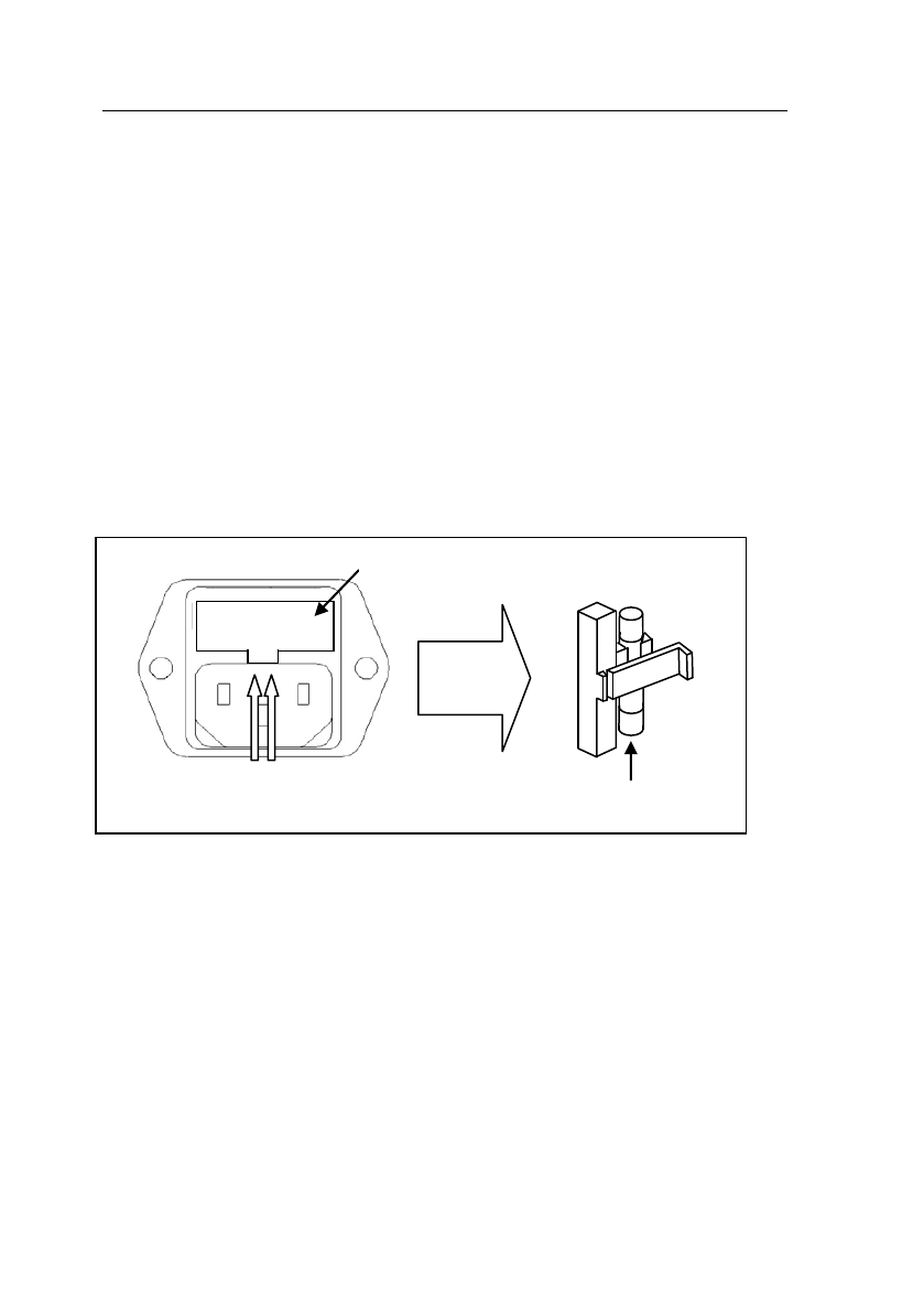
2.5 Fuse Replacement
There is a 1A, 250V rated slow blow fuse at the AC input.
Should the fuse ever get blown, follow the steps below to
replace:
1. Locate the fuse box next to the AC input connector in
the rear panel.
2. With a small flat blade screwdriver, insert into the fuse
box slit to pull and slide out the fuse box as indicated
below.
3. Check and replace fuse if necessary.
2.6 Grounding Requirements
For the safety of operating personnel, the instrument
must be grounded. The central pin on the AC plug
grounds the instrument when properly connected to the
ground wire and plugged into proper receptacle.
Fuse box slit
Fuse box
Check/Remove Fuse

21
WARNING
TO AVOID PERSONAL INJURY DUE TO SHOCK,
THE THIRD WIRE EARTH GROUND MUST BE
CONTINUOUS TO THE POWER OUTLET. BEFORE
CONNECTION TO THE POWER OUTLET, EXAMINE
ALL CABLES AND CONNECTIONS BETWEEN THE
UNIT AND THE FACILITY POWER FOR A
CONTINUOUS EARTH GROUND PATH.
THE POWER CABLE MUST MEET IEC/UL SAFETY
STANDARDS.
2.7 Signal Connections
Use RG58U 50Ω or equivalent coaxial cables for all input
and output signals to and from the instrument.
22
3 Operating Instructions
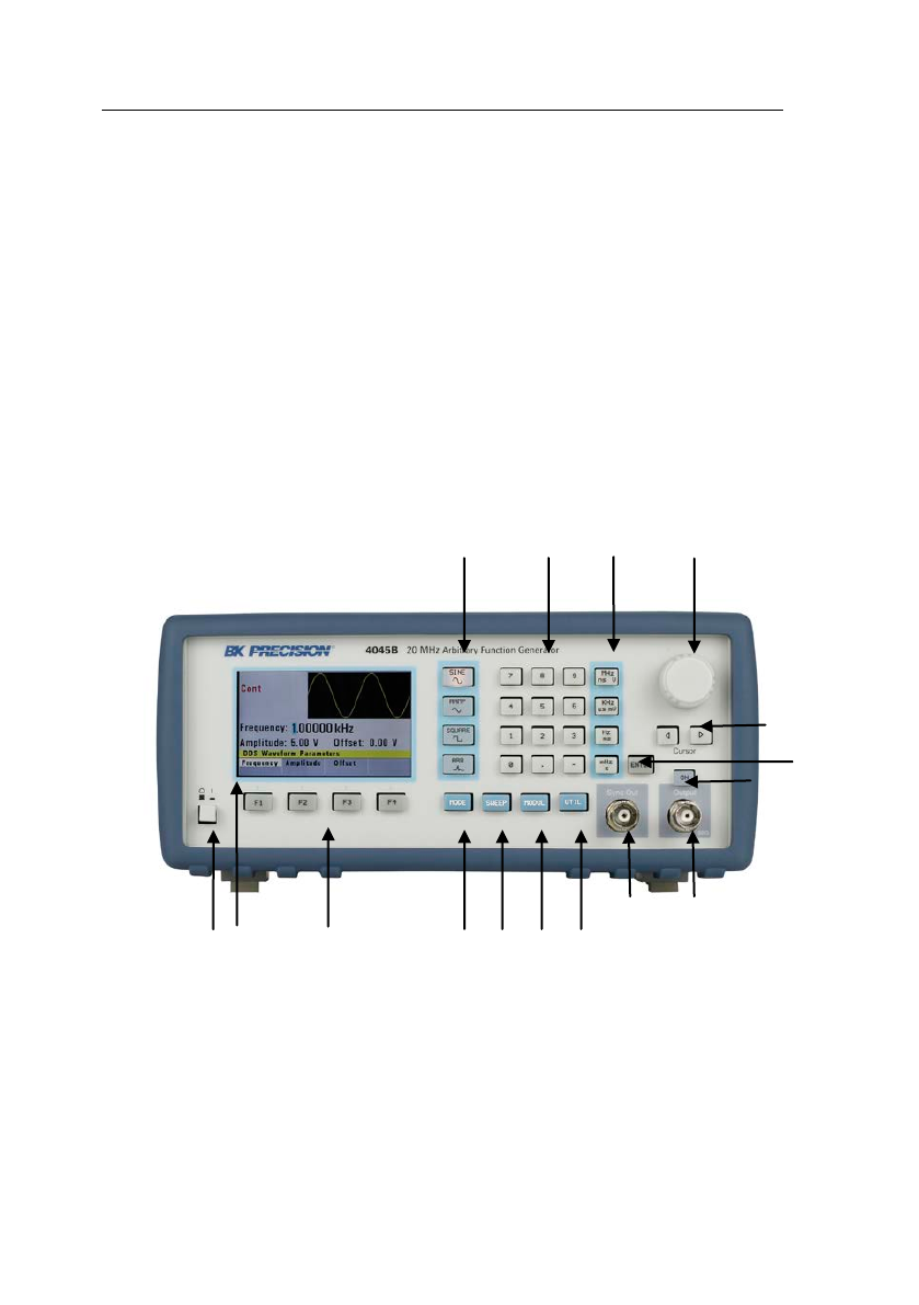
3.1 General Description
This section describes the displays, controls and
connectors of the function generator.
All controls for the instrument local operation are
located on the front panel.
1
2
3
4
5
6
7
9
8
10
11
12
13
14
15
16

23
1 Power Button Power ON/OFF unit
2 LCD Display
Displays all instrument data
and settings
3 Function Keys
F1 – F4 function keys to
select menu options
4 Waveform Buttons
Select Sine, Ramp/Triangle,
Square or Arbitrary
waveform shape
5 Numeric Keypad
Enter numeric values for
parameters
6 Units Keys
Select unit of frequency,
time, or voltage
7 Rotary Knob
Increment/decrement
numerical values or menu
selections
8 Cursor Keys
Move cursor (when visible)
left or right
9 Enter Key Confirm parameter entries
10 Output ON/OFF Enable/Disable Output
11 Output BNC Main output
12 SYNC OUT BNC Sync output
13 UTIL Button Utility menu
14
MODUL Button
Selects Modulation menu
15
SWEEP Button
Selects Sweep function
menu
16 MODE Button Selects Trigger mode menu

24
3.2 Display Window
The function generator has a color LCD display that can
display up to 400 x 240 dots. When powering on the unit,
sine waveform is selected and current settings will appear
in the display. The bottom of the display shows a menu
(selectable with function keys) that corresponds to the
function, parameter, or mode display selected.
3.3 Front Panel Controls
The front-panel controls select, display, and change
parameter, function, and mode settings.
Use the numerical keypad, rotary input knob and the
cursor movement keys to enter data into the waveform
generator.
To change a setting:
1. Press the key that leads to the parameter to change.
2. Move cursor using cursor keys to the appropriate
position in the numeric field (if applicable).
3. Use the rotary input or the numerical keyboard to
change the value of the displayed parameter. Changes
take effect immediately.
3.4 Connectors
The function generator has two BNC connectors on the
front panel where you can connect coaxial cables. These
coaxial cables serve as carrier lines for output signals

25
delivered from the function generator.
Output Connector
Use this connector to transfer the main output signal from
the function generator.
Trig In Connector
Use this connector to apply an external trigger or gate
signal, depending on the waveform generator setting, to
the generator. When the built-in frequency counter is
enabled, this connector becomes an input for the counter.
Sync Out Connector
Use this connector to output a positive TTL sync pulse
generated at each waveform cycle.
Modulation In Connector
5V p-p signal for 100% modulation, 10Kohms input
impedance with DC - >20 KHz bandwidth.
3.5 Output Connections
The waveform generator output circuits operate as a
50 Ω voltage source working into a 50 Ω load. At
higher frequencies, non-terminated or improperly
terminated output causes aberrations on the output
waveform. In addition, loads less than 50 Ω reduce
the waveform amplitude, while loads more than 50 Ω
increase waveform amplitude.

26
Excessive distortion or aberrations caused by
improper termination are less noticeable at lower
frequencies, especially with sine and triangle
waveforms. To ensure waveform integrity, follow
these precautions:
1. Use good quality 50 Ω coaxial cable and
connectors.
2. Make all connections tight and as short as
possible.
3. Use good quality attenuators if it is necessary to
reduce waveform amplitudes applied to sensitive
circuits.
4. Use termination or impedance-matching devices
to avoid reflections.
5. Ensure that attenuators and terminations have
adequate power handling capabilities.
If there is a DC voltage across the output load, use a
coupling capacitor in series with the load. The time
constant of the coupling capacitor and load must be
long enough to maintain pulse flatness.
Impedance Matching
If the waveform generator is driving a high
impedance, such as a 1 MΩ input impedance
(paralleled by a stated capacitance) of an
oscilloscope vertical input, connect the transmission
line to a 50 Ω attenuator, a 50 Ω termination and to
the oscilloscope input. The attenuator isolates the
input capacitance of the device and terminates the
waveform generator properly.
27
3.6 MENU Keys
These keys select the main menus for displaying or
changing a parameter, function, or mode.
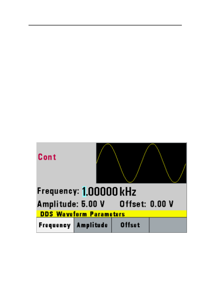
3.6.1 WAVEFORM Keys
These keys select the waveform output and display
the waveform parameter menu (frequency, amplitude
and offset).
Sine Menu

28
F1: Frequency – Selects and displays the frequency.
Change the frequency setting using the cursor keys,
rotary knob, or numerical keys.
F2: Amplitude – Selects and displays the amplitude.
Change the amplitude setting using the cursor keys,
rotary knob, or numerical keys.
F3: Offset – Selects and displays the offset
parameter. Change the offset by using the cursor
keys, rotary knob, or numerical keys. If a certain
setting cannot be produced, the waveform generator
will display a “Setting Conflict” message.
Amplitude and offset settings interact and are bound
by hardware restrictions. To obtain the desired
waveform, the amplitude and offset must satisfy the
following formula:
(Vp-p)/2 + |offset| <= 5 volts
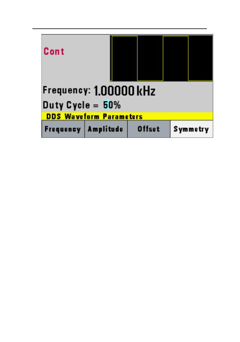
F4: Symmetry – When the Square or Triangle
waveforms are selected, the SYMMETRY (duty
cycle) parameter is available. Change the symmetry
(Triangle) or duty cycle (Square) by using the cursor
keys, rotary knob, or numerical keys. If a certain
setting cannot be produced, the waveform generator
will display a warning message.
29
Square Menu
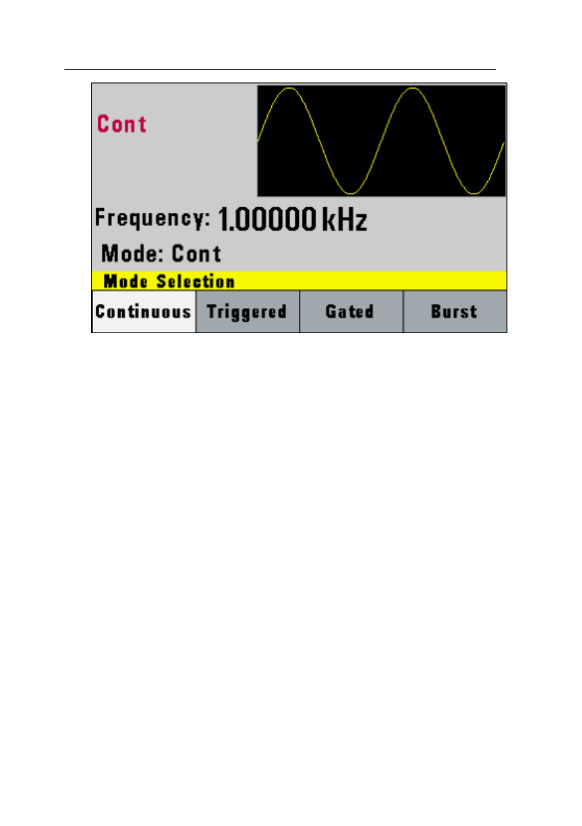
3.6.2 MODE Key
Selects the output mode: CONT (Continuous), TRIG
(Triggered), GATE (Gated), and BRST (Burst).
To select the output mode, press MODE, then press
the function key that corresponds to the desired
Mode menu option, as shown:
30
Mode Menu
F1: Continuous – Selects continuous output.
F2: Triggered – Triggers one output cycle of the
selected waveform for each trigger event.
F3: Gated – Triggers output cycles as long as the
trigger source asserts the gate signal.
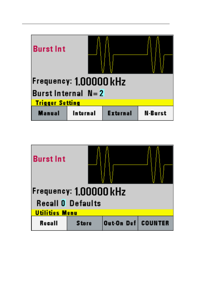
F4: Burst – Triggers ‘N’ number of output cycles for
each trigger event, where N ranges from 2 to 65,535.
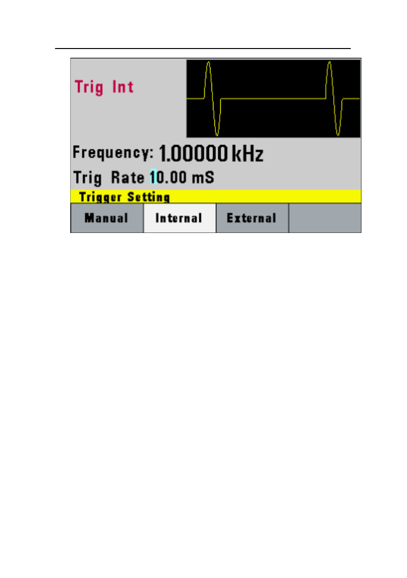
After selecting the TRIGGERED, GATED, or BURST
menu, the trigger source menu is available:
31
Trigger Menu
F1: Manual – Selects manual as the trigger source.
To trigger the waveform generator,
press this MANUAL trigger button again.
F2: Internal – Selects the internal trigger generator
as the trigger source. Change the
internal trigger rate displayed with the rotary input
knob.
F3: External – Selects the external trigger signal as
the trigger source. The trigger source
is supplied through the TRIG IN connector.
In BURST MODE, the F4 key displays N-Burst,
representing the number of burst cycles to output
with each trigger. The N value can be changed from
2 to 65,535.
32
Burst Menu
3.6.3 UTILITY Key
Utility Menu

33
F1: Recall – Recalls a previously stored front-panel
setup from the selected buffer. Change the buffer
number by using the rotary input knob. Valid storage
buffer numbers are from 1 to 19
Buffer 0 is the factory default setup.
F2: Store – Stores the current front-panel setup to
the specified storage buffer. Change the buffer
number by using the data keys or the rotary input
knob. Valid storage buffer numbers range from 1 to
19.
F3: Out-On Def – Selects the OUTPUT state on
power-up. Select ON to enable or OFF to disable the
output on power-up.
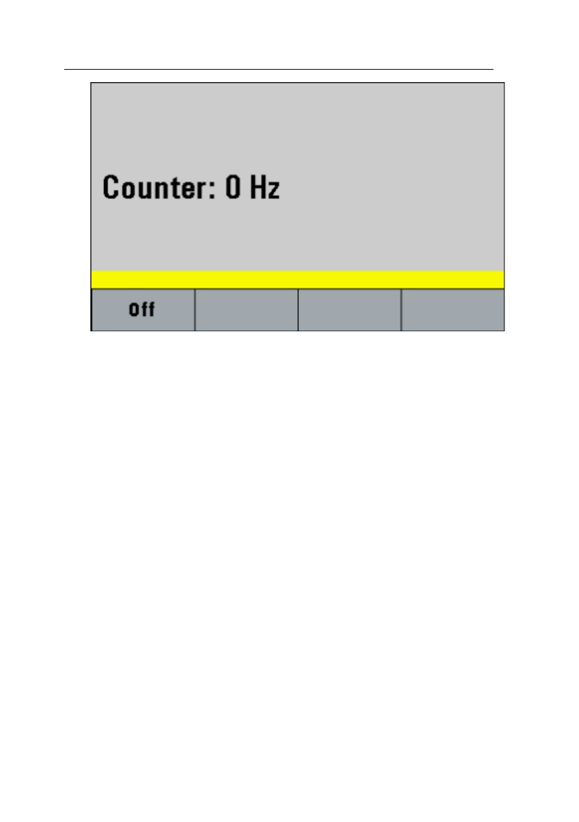
F4: COUNTER – Enables the built-in frequency
counter. The frequency of the signal connected to the
TRIG IN connector will be displayed. The counter is
auto ranging with up to 8 digits of resolution.
34
Counter Screen
Press F1 - Off to turn off the counter.
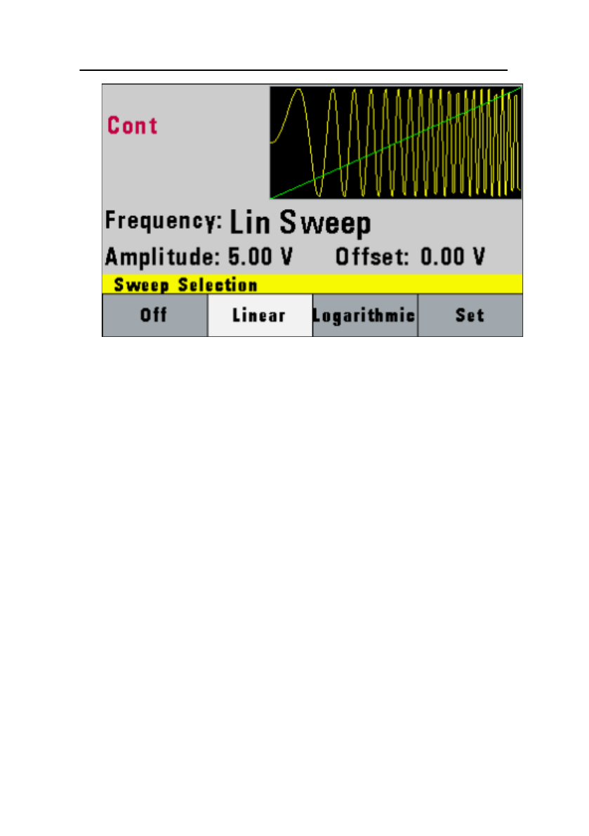
3.6.4 SWEEP Key
Selects the Sweep Mode and allows entering of
sweep parameters: Sweep Start, Sweep Stop, and
Sweep Rate.
To select the sweep mode, press SWEEP, then
press the function key that corresponds to the
desired Sweep menu option, as shown:
35
Sweep Menu
F1: Off – Disables the sweep function.
F2: Linear – Selects the Linear sweep shape.
F3: Logarithmic – Selects the Logarithmic sweep
shape.
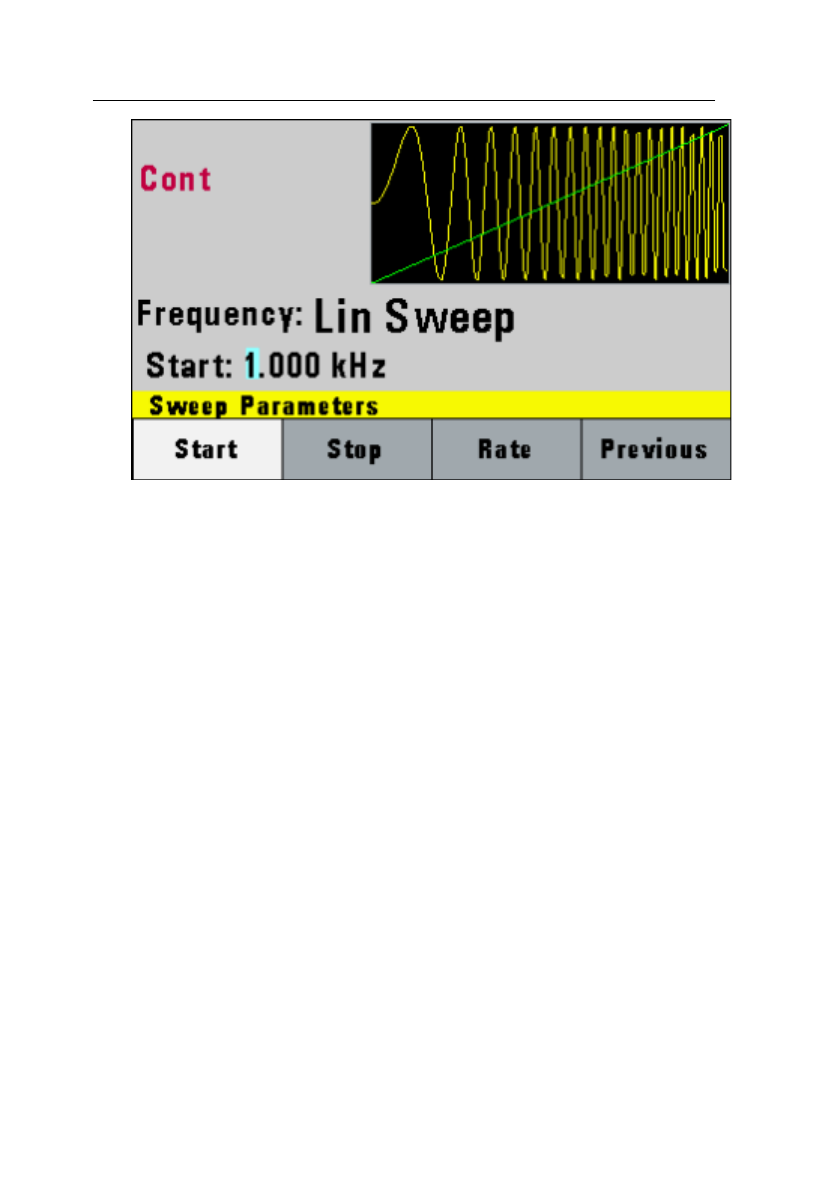
F4: Set – Defines the Sweep Start and Stop
frequencies.
36
Set Sweep Menu
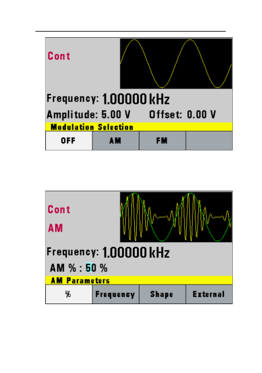
3.6.5 MODULATION Key
Selects the AM or FM Modulation mode. To select
the output mode, press MODUL key, then press the
function key that corresponds to the desired menu
option, as shown:
37
Modulation Menu
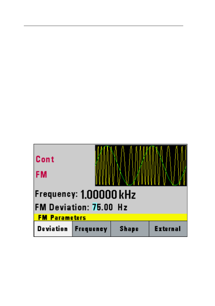
Press F2 to select AM menu:
AM Menu
38
F1: % - Defines the modulation depth (from 0 to
100%)
F2: Frequency - Selects the modulation frequency,
from 0.1 Hz to 20.00 kHz.
F3: Shape - Selects the modulating waveform
between Sine, Square, or Triangle.
F4: External - Selects and enables the external
modulation by an external signal applied to the
Modulation In connector in the rear panel.
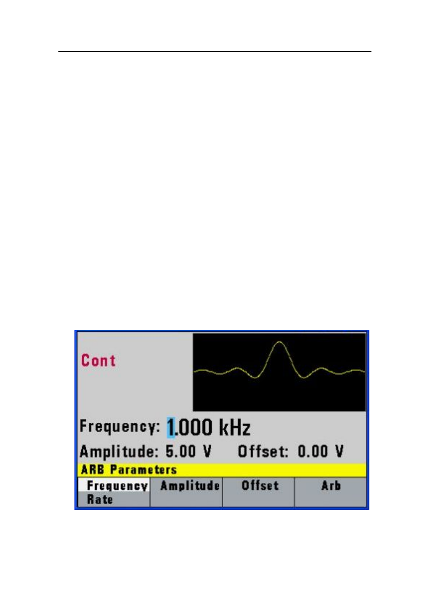
Press F3 to select FM menu:
FM Menu
39
F1: Deviation - Defines the FM deviation frequency.
F2: Frequency - Selects the modulation frequency,
from 0.1 Hz to 20.00 kHz.
F3: Shape - Selects the shape of the modulating
waveform between Sine, Triangle, or Square.
F4: External - Selects and enables the external
modulation by an external signal applied to the
Modulation In connector in the rear panel.
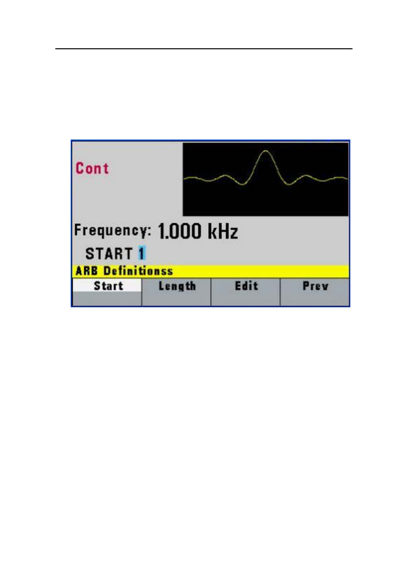
3.6.6 ARBITRARY Key
Selects the Arbitrary waveform menu shown
below:
Arbitrary Menu

40
F1: Frequency Rate - (Frequency) Selects
and displays the frequency. Change
the frequency setting using the cursor
keys, rotary knob or numerical keys. If
a certain wavelength can't produce the
waveform at the desired frequency, the
waveform generator will display an
“Out of Range” error message.
Displays the Point Rate (for Arbitrary
Waveform only). The Rate parameter
governs the rate at which waveform
points are executed and thus the
frequency of the output. When you set
this parameter, the waveform
generator will keep that execution rate
for all waveform lengths until it is
changed.
F2: Amplitude - Selects the Amplitude
parameter.
In Arbitrary mode, this setting defines
the maximum peak-to-peak amplitude
of a full-scale waveform. If the
waveform does not use the full scale
(data points from -2047 to +2047),
then its actual amplitude will be
smaller.
F3:Offset -Selects the Offset parameter.
Change the offset by using the cursor
keys, rotary dial or numerical keys. If a
certain setting cannot be produced, the
41
waveform generator will display a
“Setting Conflict” error message.
F4: Arb - Selects the Arbitrary
waveform editing menu:
Arbitrary Editing Menu
F1: Start - Selects the arbitrary waveform
start address.
F2: Length - Selects the arbitrary waveform
length. Use the START and LENGTH
keys to mark a selection of the
waveform memory that will be
executed.
Changing one of the arbitrary
parameters as start and length cause
an updating of the output waveform to
the new parameters. When exiting the
Arbitrary Menu by selecting a different

42
waveform, a message to save the
Arbitrary wave will be displayed. Select
YES or NO to save the new waveform.
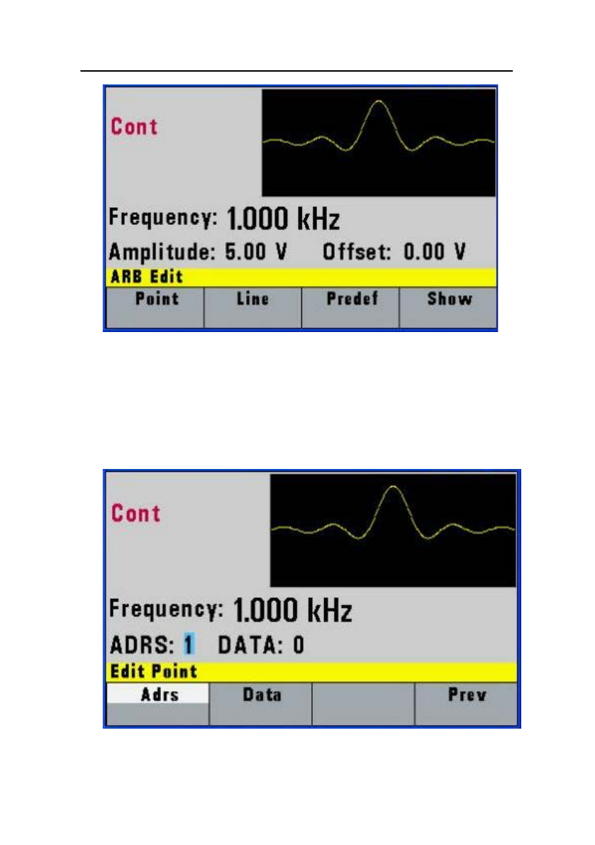
3.6.7 Arbitrary EDIT Menu
Enters data for creating arbitrary waveforms.
You can enter data one point at a time, as a
value at an address, draw a line from one
point (a value at an address) to another point,
create a predefined waveform, or combine
these to create complex waveforms. The valid
data values range is -2047 to 2047. The valid
waveform memory addresses range from 1 to
1,000.
The data value governs the output amplitude
of that point of the waveform, scaled to the
instrument output amplitude. Therefore, a
value of 2047 corresponds to positive peak
amplitude, 0 corresponds to the waveform
offset, and -2047 corresponds to the negative
peak amplitude.
43
Edit Menu
F1: Point - This menu allows point-by-
point waveform editing. When
selected, the following menu is
displayed:
Point Menu
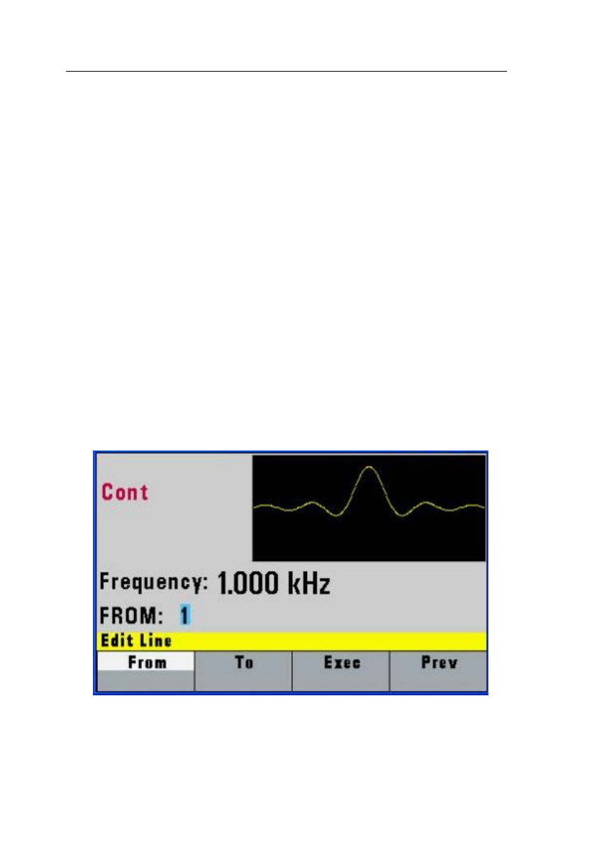
44
F1: Adrs - Select the current
address in the arbitrary
waveform memory.
F2: Data - Selects the data
point value at the
current address.
You can change
the point value
from -2047 to 2047.
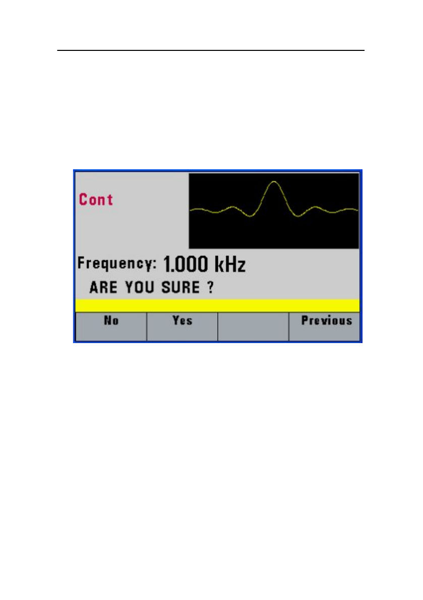
F2: Line - This menu allows a line to be
drawn between two selected
points.
When selected, the following
menu is displayed:
Line Menu
45
F1: From - Selects the starting point
address.
F2: To - Selects the ending point
address.
F3: Exec - Displays the Confirmation
menu, F1:NO and F2:YES
Confirmation Menu
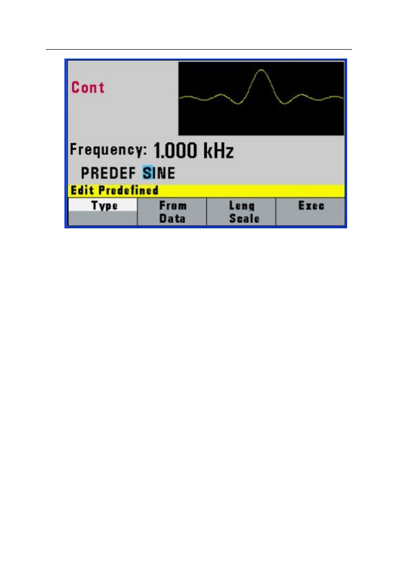
F3: Predef - (Predefined Waveforms)
Selects one of the
predefined waveforms:
Sine, Triangle, Square and
Noise. Displays the
Predefined waveforms
menu:
46
Predefine Menu
F1: Type - Use the rotary dial to
select the waveform Sine,
Triangle, Square or Noise.
If Noise function is selected,
a submenu is displayed to
allow adding the noise to an
available waveform or to
generate it as a new noise
waveform.
F2: From Data - Selects the
starting point of the
generated waveform and
data value.
F3: Leng/Scale - Selects the
length of the predefined

47
waveform (number of points
for a full wave). Different
waveforms have different
limitations on the length, as
shown in Table 3-1.
Table 3-1: Waveform Length Limits for Predefined
Waveforms
Wave
Minimum
Length
Divisible by
Sine
16
4
Triangle
16
4
Square
2
2
Noise
16
1
F3: Scale - Selects the scale factor
of the waveform. 100% means that the
waveform spans the full scale of -2047
to 2047. Scale factors are limited by
the point data value of the starting
point and automatically calculated by
the unit.
F4: Exec - Prompts you to confirm
whether to execute the selected
predefined waveform. Press NO to
abort executing the predefined
waveform; press YES to execute the
predefined waveform. On the NOISE
48
function menu options, ADD and NEW
are available. Select ADD to add
noise to an existing waveform, or NEW
to create a new noise waveform.
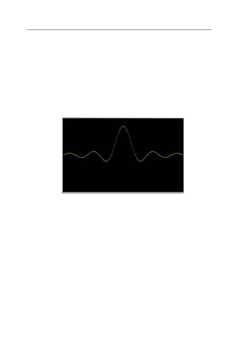
F4:Show - Displays the Arbitrary
waveform on the full LCD display.
Press any button to return to the
MENU selection display.
Full Display
3.7 ON Key
Use this key to control the main output signal. When
the output is active, the ON key will be lit. By default,
this will be ON (enabled) from a power-up. This can
be changed by changing the Out-On Def settings
from the UTILITY menu.

49
3.8 Cursor Keys
Use these keys to move the cursor (when visible)
either left or right. They are used in conjunction with
the rotary input knob to set the step size of the rotary
input knob.
3.9 Rotary Input Knob
Use this knob to increase and decrease numeric
values. The cursor indicates the low-order position of
the displayed value which changes when you rotate
the knob (for straight numeric entries only). For other
types of data, the whole value changes when you
rotate the knob.
3.10 Power-On Settings
At power-on, the waveform generator performs a
diagnostic self-test procedure to check itself for
errors. If an error is found, an error code and text will
appear in the display window. Other error codes
appear when you enter an invalid front-panel setting.
For more information on error codes, see the Error
Indication section.
When the waveform generator finishes the diagnostic
self-test routine, it enters the local state (LOGS) and

50
assumes power-on default settings. Table 1 lists the
factory default settings or selected after RECALL 0.
Table 1 – Power-on Default Settings
Key Function
Value
Description
Function
Sine
Output Waveform
Frequency
1.0000 kHz
Waveform Frequency
Amplitude
5.00 V
Peak-to-peak output
amplitude
Offset
0.00 V
Zero DC offset
Output
OFF
Output disabled
Sweep
OFF
Sweep function disabled
Modulation
OFF
Modulation function
disabled
N-BURST
2
Wave per burst for burst
mode
Trig Source
Continuous
Continuous trigger
Trig Rate
10 ms
Internal trigger rate
3.11 Memory
The waveform generator uses non-volatile flash
memory for storing the front panel settings.
Up to 20 front panel settings can be stored (includes
storage location 0 for factory default settings). One
1000 points Arbitrary waveform is stored in the flash
non-volatile memory.

51
3.12 Displaying Errors
The waveform generator displays error messages
when front-panel settings are either invalid or may
produce unexpected results.
Table 2 – Error Messages
Message
Text
Description
Out of range
The set value is out of the
instrument’s limits.
Setting
conflict
Settings conflict with another
parameter setting or value.
Empty
location
Attempt to recall settings from an
empty storage location.
Trig rate
short
Internal trigger rate is too short to
output waveform or burst.
Save RAM
New firmware installed.
Must divide
by 4
Predefined wave length must be
divisible by 4.
Must divide
by 2
Predefined wave length must be
divisible by 2.

52
3.13 Quick Start
This section explains how to generate various
waveforms and modify the output waveform.
* Generating a waveform output
* Modifying waveform output
* Storing and recalling a waveform generator
setup
3.13.1 Selecting a Standard Waveform
You can select several standard waveforms as: sine,
triangle, square. Creating a standard waveform
requires selecting the waveform type, parameters
and their settings that define the waveform.
Generating a standard waveform requires the
following:
* Selecting the waveform
* Setting the output frequency
* Setting the output amplitude and offset
3.13.2 Setting the Output
To set the output channel, press the Output ON key.
The key will lit indicating the output is enabled.

53
3.13.3 Using Voltage Offset
Through the offset parameter you can add a positive
or negative DC level to the output waveform.
To set voltage offset:
1. Select a waveform to display its menu.
2. Press F3:Offset to display the offset setting.
3. Use the rotary input knob or the numerical keys to
set the voltage offset.
To turn the voltage offset OFF, repeat the steps
above, but set the offset voltage level to 0.
3.13.4 Storing and Recalling a Waveform
Generator Setup
You can store front-panel setups inside the internal
non-volatile flash memory. When you recall a stored
setup, the front-panel settings change to match the
settings in the stored setup.
Storing Setups
To store the front-panel setup:
1. Press UTILITY to display the menu.
2. Press F2:Store to select the Store mode.
3. Use the rotary input knob to select a buffer
number. Valid buffer numbers range from 1 to 19
Buffer 0 is a read-only buffer that contains the
default setup/power-on settings from Table 1.

54
The function generator will overwrite and store
settings into a buffer that had settings previously
stored inside without a warning.
Recalling Setups
To recall stored front-panel setup:
1. Press UTILITY to display the menu.
2. Press F1:Recall to select the Recall mode.
3. Use the rotary input knob to select a buffer
number. Valid buffers numbers range from 0 to 19.
Buffer 0 is a read-only buffer that contains the
default power-on setup.

55
3.13.5 Creating an Arbitrary Waveform
You can create an arbitrary waveform using the
following methods:
* Enter individual data points
* Draw lines between data points
* Create a predefined waveform
* Combine any of these methods
NOTE
You can use the free downloadable software to
create arbitrary waveforms.
For more information, please visit
www.bkprecision.com.
You can program any number of waveforms into
waveform memory, keeping in mind the
addresses where one waveform ends and the
other begins.
The waveform's frequency and amplitude are
influenced by the number of data points and
their value in the waveform.
3.13.6 Entering Individual Data Points
The most basic way to program an arbitrary
waveform is to enter data points for the
waveform, one data point at a time. While this
can become tedious the auto-increment function
helps this process.
To enter individual data points into waveform

56
memory, follow these steps:
1. Press ARB main key to display the
selection menu.
2. Press F4 :ARB to display the arbitrary
menu.
3. Press F3:EDIT to display the Edit menu.
4. Press F1:POINT, to select the point by
point programming mode.
5. Press F1:ADDRESS
6. Use the rotary knob or the numerical keys
to enter the address.
7. Press F2:DATA.
8. Use the rotary knob r the numerical keys to
enter the value for the data point. Valid
entries range from –2047 to 2047.
9. Repeat steps 5 through 9 until you finish
programming your arbitrary waveform.
NOTE
Each time you press ENTER to complete a data
point entry in numerical mode, the
auto-increment address advances by one.
3.13.7 Setting the Arbitrary Frequency
The arbitrary waveform frequency is a function of the
number of data points used to run the waveform (the
length parameter in the ARBITRARY menu) and the
waveform execution point rate. The waveform

57
execution point rate is the execution time between
each point in the waveform. The total time taken to
run one period of the waveform is
given by:
number of points X rate
Because the output frequency is a function of the rate
and the number of points being executed, the formula
is given as:
𝑓𝑟𝑒𝑞𝑢𝑒𝑛𝑐𝑦 =
1
𝑁𝑢𝑚𝑏𝑒𝑟 𝑜𝑓 𝑝𝑜𝑖𝑛𝑡𝑠 𝑥 𝑟𝑎𝑡𝑒
For example, to set the output frequency to 1000Hz,
given the number of data points used for the
waveform output is 1000, calculate:
𝑟𝑎𝑡𝑒 =
1
1000 𝑝𝑜𝑖𝑛𝑡𝑠 𝑥 1000 𝐻𝑧 = 1𝜇𝑠
EXAMPLE: Setting the Output Frequency
To set the output frequency of a 1000 point waveform
in execution memory to 1000Hz, set the rate to 1us:
ACTION
KEYSTROKES
Step 1: Set the output rate to 1 us
(equivalent to 1000 Hz output
frequency
PARAMETER
F1:RATE
1
kHz/us

58
3.13.8 Setting the Amplitude
The following equation represents the relative
output amplitude voltage relationship between
the front-panel amplitude peak-to-peak setting
and the data point values in waveform memory:
𝑜𝑢𝑡𝑝𝑢𝑡 𝑣𝑜𝑙𝑡𝑎𝑔𝑒
= 𝐴𝑚𝑝𝑙𝑖𝑡𝑢𝑑𝑒 𝑝 − 𝑝 𝑠𝑒𝑡𝑡𝑖𝑛𝑔 𝑥 𝑑𝑎𝑡𝑎 𝑝𝑜𝑖𝑛𝑡 𝑣𝑎𝑙𝑢𝑒
4095
+𝑜𝑓𝑓𝑠𝑒𝑡
Where 4095 is the data point value range in
waveform memory.
Table 3-4: Relative Amplitude for Waveform Output
(Examples)
Front Panel
Amplitude
Setting
Data Point
Value
Relative Output
Amplitude Voltage
5V p-p
2047
2.5 V positive peak
5V p-p
0
0V (offset voltage)
10V p-p
2047
5V positive peak
3.13.9 Executing an Arbitrary Waveform
To load a waveform into execution memory,
specify its starting address and length in the
ARBITRARY menu.
1. Select the channel to ON.

59
2. Press the ARB key and select the F4:ARB
function.
3. Press F1:START to set the address. Valid
entries range from 1 to 999.
4. Press F2:LENGTH to display the length of the
waveform.
6. Use the rotary input knob or the numerical
keys to enter the waveform length. Valid entries
range from 2 to 1000.

4 Programming
4.1 Overview
This section provides detailed information on programming
the generator via the USB (virtual COM) interface.
4.1.1 Connecting to USB (Virtual COM)
Interface
Currently, the USB (virtual COM) interface supports
Windows® XP/7 operating systems.
To connect to a PC for remote communication, please
follow the steps below:
For Windows 7:
1. The USB driver is included in the CD that comes with
the instrument. You can also go to
www.bkprecision.com and browse this product’s page to
find and download the USB driver.
2. Connect the included USB Type A to Type B cable to
the generator and the computer, then power on the
instrument.
3. On most operating systems, it will attempt to
automatically install, showing the following screen:
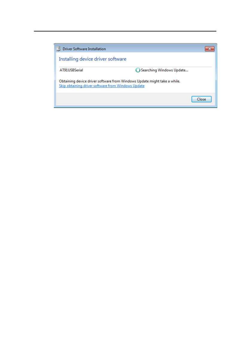
61
4. Click the “Close” button to stop the automatic search of
the driver from Windows Update.
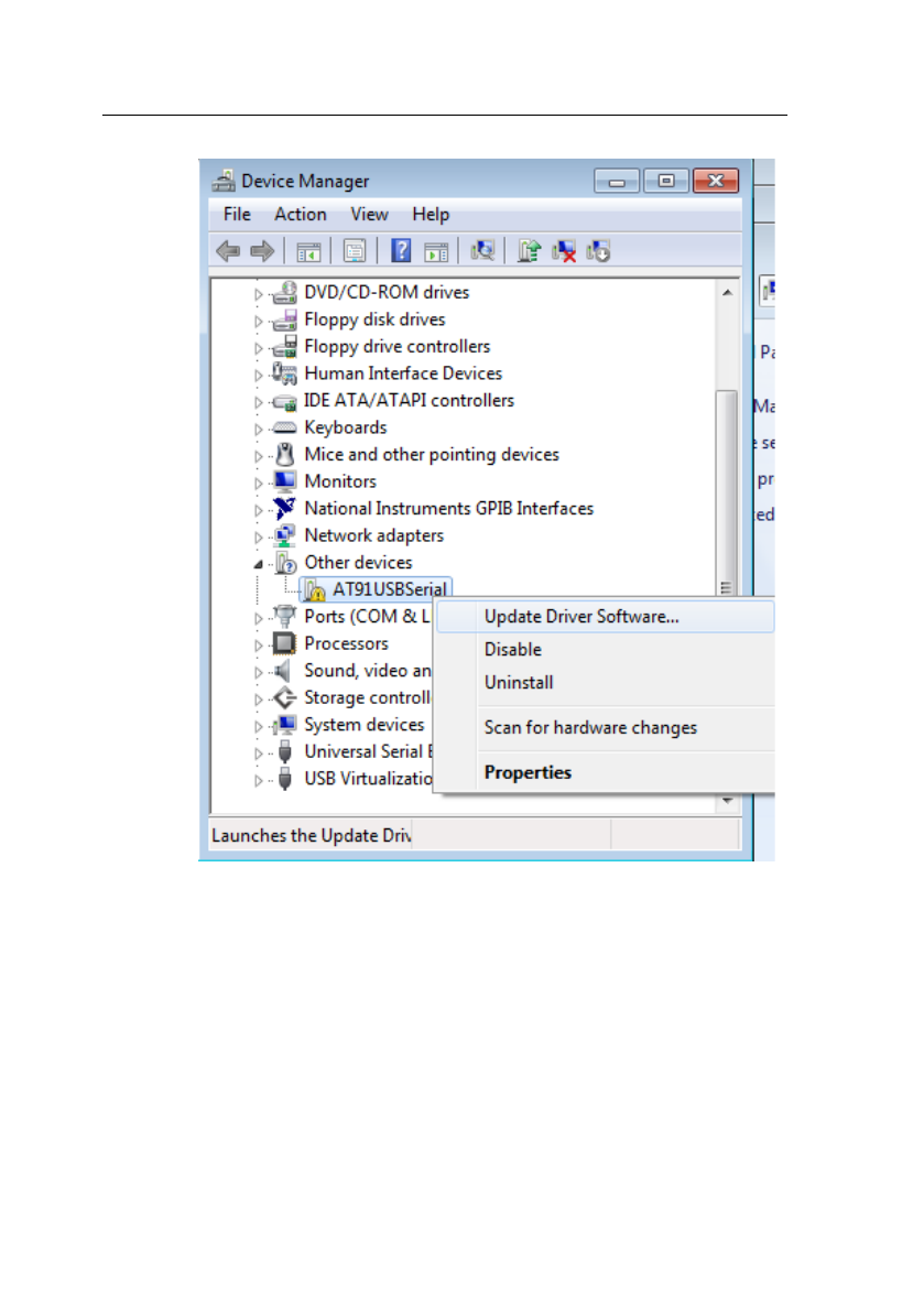
5. Now, go to Device Manager on the computer (Open up
the “start” button, and right-click “Computer” and select
“Properties”. Click “Device Manager” link on the top left
of the side menu)
6. There will be an item listed under “Other devices”
labeled “AT91USBSerial”. Right-click the item and
select “Update Driver Software…”
62
7. In the following window, select “Browse my computer for
driver software”, and following this, select “Let me pick
from a list of device drivers on my computer”.
8. Now there will be a window listing Common hardware
types. Click the “Next” button and select on the
following screen “Have Disk…”
9. From the “Install From Disk” window, click “Browse…”
and locate and double-click the USB driver file
downloaded from the website labeled
“atm6124_cdc.inf”.
63
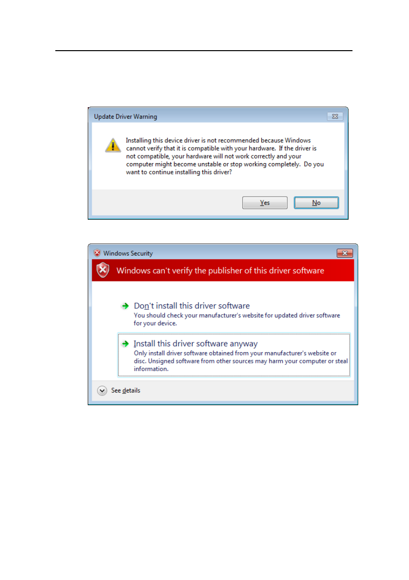
10. Now click “OK”. It will show in the window under Model
“AT91 USB to Serial Converter”. Click “Next” and you
will get the following note:
11. Go ahead and click “Yes”. When you get the following
prompt, select “Install this driver software anyway”.
12. The driver will now install. Once finished, under “Device
Manager”, you should see under “Ports (COM & LPT)”
an item labeled “BK Precision USB to Serial Converter
(COM#)”. The “COM#” is the com port that can be used
to access the virtual COM port for remote
communication.
64
For Windows XP:
1. The USB driver is included in the CD that comes with
the instrument. You can also go to
www.bkprecision.com and browse this product’s page to
find and download the USB driver.
2. Connect the included USB Type A to Type B cable to
the generator and the computer, then power on the
instrument.
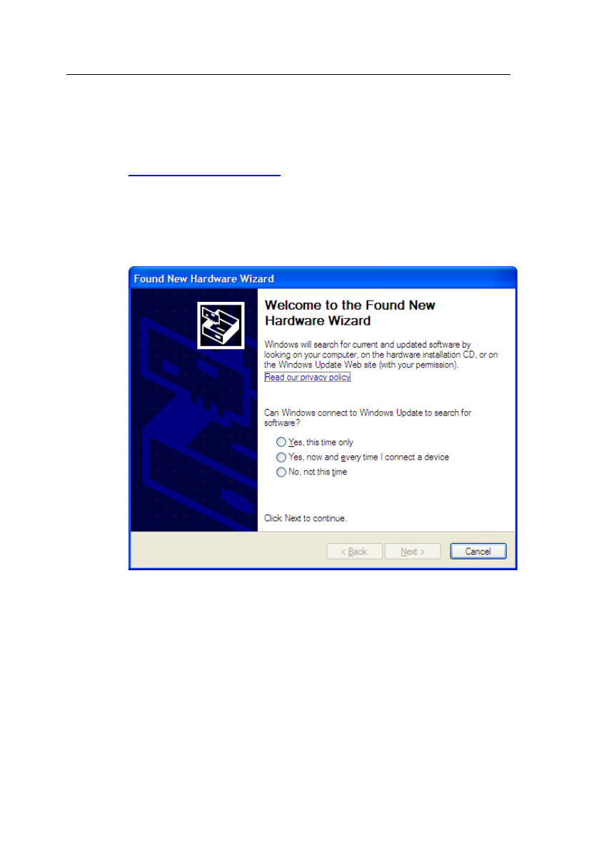
3. The following screen will appear.
4. Select “No, not this time” and click “Next”.
5. In the following screen, select “Install from a list or
specific location (Advanced)” and click “Next”.
6. In the next screen, select “Don’t search. I will choose the
driver to install.” and click “Next” again.
7. In the following screen, click “Have Disk…”
8. From the “Install From Disk” window, click “Browse…”
and locate and double-click the USB driver file
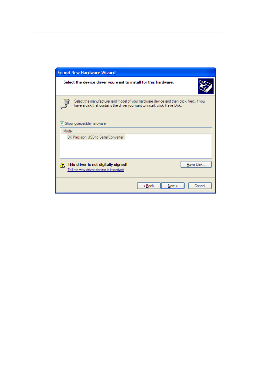
65
downloaded from the website labeled
“atm6124_cdc.inf”. Select it and click “OK”.
9. The following screen will appear.
10. Click “Next”, and a prompt will appear:
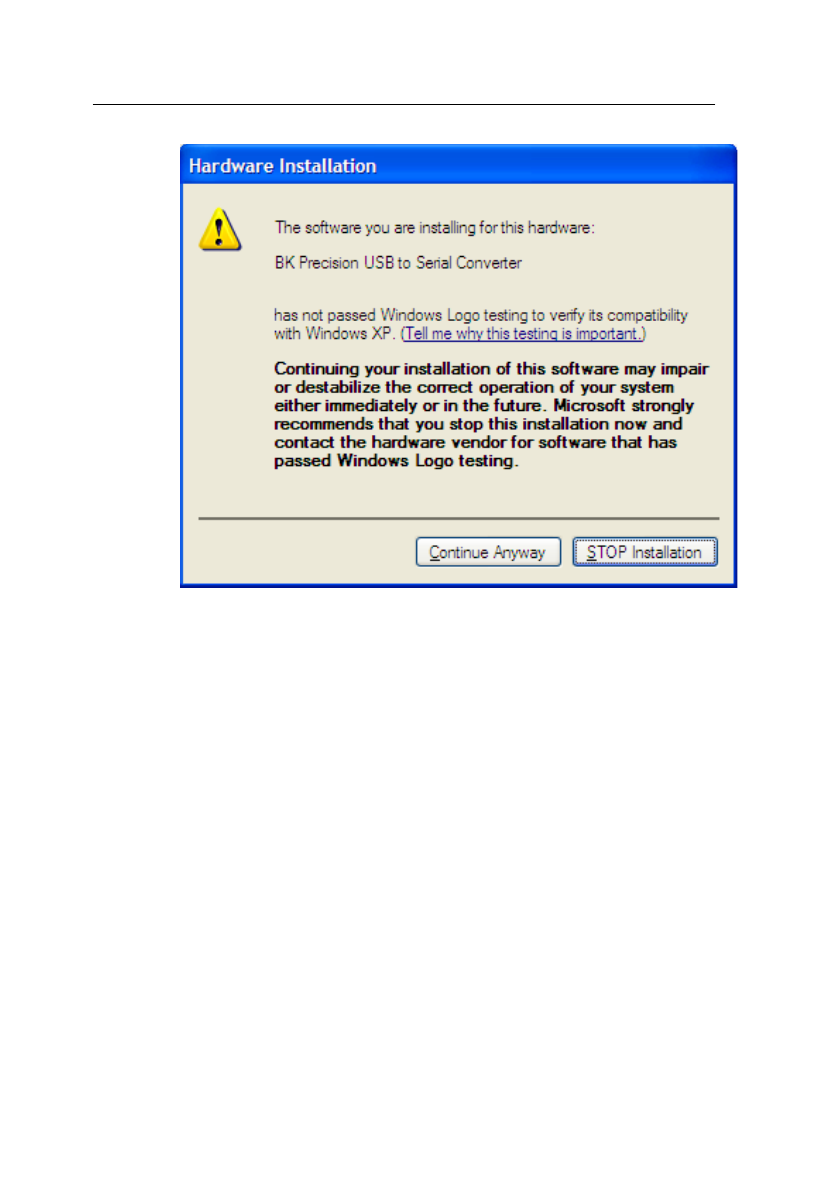
66
11. Click on “Continue Anyway” and the driver will now
install.
12. The driver will now install. Once finished, under “Device
Manager” (This can be opened by: Right-click “My
Computer”->Select “Properties”->Select “Hardware” tab-
>Click “Device Manager”), you should see under “Ports
(COM & LPT)” an item labeled “BK Precision USB to
Serial Converter (COM#)”. The “COM#” is the com port
that can be used to access the virtual COM port for
remote communication.
4.1.2 USB (Virtual COM) Settings
The USB (virtual COM) interface settings for the
communication port are as follows:

67
BAUDRATE: 115200
PARITY: NONE
DATA BITS: 8
STOP BIT: 1
FLOW CONTROL: NONE
4.2 Device States
The device may be in one of the two possible states
described below.
4.2.1 Local State (LOCS)
In the LOCS state, the device may be operated from the
front panel.
4.2.2 Remote State (REMS)
In the REMS state, the device may be operated from the
USB interface. Actuating any front panel key will cause the
device state to revert to the LOCS.
4.3 Message Exchange Protocol
The device decodes messages using the Message
Exchange Protocol similar to the one defined in IEEE
488.2. The following functions implemented in the MEP
must be considered:

68
4.3.1 The Input Buffer
The device has a 128-byte long cyclic input buffer.
Decoding of remote messages is begun as soon as the
input buffer is not empty, that is, as soon as the controller
has sent at least one byte to the device. Should the input
buffer be filled up by the controller faster than the device
can remove the bytes and decode them, the bus
handshake (CTS/RTS) is used to pause data transfer until
room has been made for more bytes in the buffer. This
prevents the controller from overrunning the device with
data.
4.3.2 The Output Queue
The device has a 100-byte long output queue in which it
stores response messages for the controller to read. If at
the time a response message is formatted the queue
contains previously formatted response messages, such
that there are not enough places in the queue for the new
message, the device will hold off putting the message in
the queue until there is a place for it.
4.3.3 Response Messages
The device sends a Response Message in response to
a valid query. All queries return a single Response
Message Unit.

69
4.4 Instrument Identification
The *IDN? common query is used to read the
instrument's identification string. The string returned is as
follows:
BK, MODEL 4045B,0,V0.1
The “V0.1” reflects the firmware version number
and will change accordingly.
4.5 Instrument Reset
The *RST common command effects an instrument
reset to the factory default power up state.
4.6 Command Syntax
4.6.1 General Command Structure
A Program Message is defined as a string containing one
Program Message Units, which is an instrument command
or query. The Program Message is terminated by the
Program Message Terminator.
The Program Message Terminator consists of optional
white space characters, followed by the Linefeed (LF)
character (0x0A).

70
The Program Message Unit can be divided into
three sections as follows:
a) Program Header
The Program Header represents the operation to be
performed, and consists of ASCII character mnemonics.
Two types of Program Headers are used in the
MODEL 4045B: Instrument-control headers and Common
Command and Query headers. Common Command and
Query Program Headers consist of a single mnemonic
prefixed by an asterisk ('*').
The mnemonics consist of upper - or lower-case alpha
characters.
Example: The command to set the frequency to
1KHZ may be written in the following ways:
FREQ 1KHZ
FREQ 1000HZ
FREQ 1000
FREQ 1E3
freq 1khz
freq 1000hz
freq 1000
freq 1e3
b) Program Header Separator

71
The Program Header Separator is used to separate the
program header from the program data. It consists of one
or more white space characters, denoted as <ws>.
Typically, it is a space.
c) Program Data
The Program Data represent the values of the parameters
being set, for example, the '1KHZ' in the above
examples. Different forms of program data are accepted,
depending on the command. The Program Data types
used in the instrument are:
i) Character program data
This form of data is comprised of a mnemonic made up of
lower - or upper-case alpha characters. As with Program
Header mnemonics, some Character Data mnemonics
have short and long forms. Only the short or the long form
may be used.
ii) Boolean data
Boolean data indicate that the parameter can take one of
two states, ON or OFF. The parameter may be character
type
ON or OFF
or numeric. A numeric value is rounded to an integer. A
non-zero result is interpreted as 1 (ON), and a zero result
as 0 (OFF).
Queries return the values 0 or 1.

72
iii) NRf
This is a decimal numeric data type, where
NR1 indicates an integer number,
NR2 indicates a fixed point real number, and
NR3 indicates a floating point real number.
iv) Numeric value program data
This data type defines numeric values, as well as special
cases of Character Data. Numeric values may be
specified in any of Integer, Fixed Point or Floating Point
format. All parameters which have associated units accept
a suffix, which may be specified using upper or lower-case
characters. When the suffix is not specified, the numeric
value is accepted in the default units, which are Hertz for
frequency, Seconds for time, and Volts for voltage. To set
the frequency to 1KHz we can send one of the following
commands:
FREQ 1000
FREQ 1E3
The special forms of character data accepted as
numbers are
MAXimum: sets the parameter to its maximum
value.
MINimum: sets the parameter to its minimum
value.

73
For example, to set the frequency to its maximum
value we can send the command
FREQ MAX
Some Program Message Units either require, or can
accept, more than one data element. Program data
elements are separated from each other by the Program
Data Separator. It is defined as optional white space
characters followed by a comma (','), which in turn is
followed by optional white space characters.
There are two types of Program Message Units:
Command Message Units and Query Message Units. A
Query differs from a Command in that the Program
Header is terminated with a question mark ('?'). For
example, the frequency might be queried with the
following query:
FREQ?
Some Query Message Units accept data, giving the device
more specific information about what is being queried. In
many cases the Query Message Unit may optionally be
supplied with the MIN or MAX mnemonics as data. This
tells the device to return the minimum or maximum value
to which the parameter may currently be set. For example,
FREQ? MAX

74
will return the maximum value to which the
frequency may currently be set.
Not all Program Message units have query forms (for
example, SAV), and some Program Message Units might
have only the query form (for example IDN?).
The instrument puts the response to the query into the
output queue, from where it may be read by the controller.
NOTE: All commands should be terminated with a
<CR> carriage return or <LF> line feed character. Any
response string from a query command has both
<CR> and <LF> characters appended. For example,
an amplitude query command will return
1.23<CR><LF>.
4.7 Status Reporting
The instrument is capable of reporting status events and
errors to the controller.
4.7.1 The Error Queue
The error queue is used to store codes of errors detected
in the device. It is implemented as a cyclic buffer of length
10. The error queue is read with the following query:
ERR?

75
The first error in the queue is returned, and the queue is
advanced.
4.7.2 Error Codes
The negative error codes are defined by SCPI. Positive
codes are specific to the instrument.
The error message is returned in the form
<error number>,"<error description>"
A table of error numbers and their descriptions is
presented here.
No error reported
0 - No error
Command Errors
A command error is in the range -199 to -100, and
indicates that a syntax error was detected. This includes
the case of an unrecognized header.
-100 Command Error
-101 Invalid character
-102 Syntax error
-103 Invalid separator
-104 Data type error
-108 Parameter not allowed

76
More parameters than allowed were
received
-109 Missing parameter
Fewer parameters than necessary
were received
-110 Command header error
-111 Header separator error
-112 Program mnemonic too long
The mnemonic must contain no more
than 12 characters.
-113 Undefined header
-120 Numeric data error
-121 Invalid character in number
-123 Exponent too large
-124 Too many digits
-128 Numeric data not allowed
A different data type was expected
-131 Invalid suffix
-134 Suffix too long
-138 Suffix not allowed
-140 Character data error.
-141 Invalid character data.
Incorrect character data were
received.
-144 Character data too long
Character data may contain no more
than 12 characters.
-148 Character data not allowed
-158 String data not allowed
-161 Invalid block data
An error was found in the block data
-168 Block data not allowed

77
-178 Expression data not allowed
Execution Errors
An execution error indicates that the device could not
execute a syntactically correct command, either since the
data were out of the instrument's range, or due to a device
condition.
-200 Execution error
An attempt was made to RECALL the
contents of an uninitialized stored
setting buffer.
-211 Trigger ignored.
The *TRG common command was
ignored due to the device not being in
the correct state to execute the
trigger.
-220 Parameter error.
A parameter is in the correct range,
but conflicts with other parameters.
-221 Settings conflict.
The parameter is out of range due to
the current instrument state.
-222 Data out of range.
-223 Too much data.
The arbitrary waveform memory limit
has been exceeded.
-224 Illegal parameter value.

78
The parameter value must be
selected from a finite list of
possibilities.
Device-Specific Errors
An error specific to the device occurred.
-315 Configuration memory lost.
Device memory has been lost.
-330 Self-test failed.
-350 Queue overflow.
Error codes have been lost due to
more than 10 errors being
reported without being read.
Query Errors
A query error indicates that the output queue control
has detected a problem. This could occur if either an
attempt was made to read data from the instrument if none
was available, or when data were lost. Data could be lost
when a query causes data to be formatted for the
controller to be read, and the controller sends more
commands without reading the data.

79
-410 Query INTERRUPTED.
Data were sent before the entire
response of a previous query was
read.
-420 Query UNTERMINATED.
An attempt was made to read a
response before the complete
program message meant to generate
that response was sent.
Warnings
The execution of some commands might cause an
undesirable instrument state. The commands are
executed, but a warning is issued.
500 Trigger rate short
510 Output overload
"Trigger rate short" means that the period of the waveform
is larger than the value of the internal trigger rate. Thus
not every trigger will generate a cycle (or burst) of the
waveform.

80
4.8 COMMON COMMANDS
4.8.1 System Data Commands
*IDN? - Identification query
The identification query enables unique identification of
the device over the GPIB. This query should always be
the last in a program message. It returns a string with four
fields:
Manufacturer name
Model name
Serial number (0 if not relevant)
Version number
Command
Type: Common Query
Syntax: *IDN?
Response: BK, MODEL 4045B,0,V1.1
4.8.2 Internal Operation Commands
*RST - Reset command
The Reset command performs a device reset. It
causes the device to return to the factory default power up
state.
Type: Common Command
Syntax: *RST

81
4.8.3 Device Trigger Commands
a) *TRG - Trigger command
This command is analogous to the IEEE 488.1 Group
Execute Trigger interface message, and has the same
effect. It is used to trigger the device to output a wave, and
is accepted only when the trigger mode is set to Trigger,
Gate or Burst, and the trigger source is set to BUS.
Type: Common Command
Syntax: *TRG
4.8.4 Stored Settings Commands
*RCL - Recall instrument state
This command is used to restore the state of the device to
that stored in the specified memory location.
Arguments
Type <NRf>
Range 0 to 19 (4045B). Non integer values are
rounded before execution
Type: Common Command
Syntax: *RCL<ws><NRf>
Example: *RCL 0 (Recall default state)
*RCL 9

82
*SAV - Save instrument state
This command is used to store the current instrument
state in the specified memory location.
Arguments
Type: <NRf>
Range: 0 to 9. Non integer values are rounded
before execution
Type: Common Command
Syntax: *SAV<ws><NRf>
Example: *SAV 2
Stored setting location 0 stores the factory defaults, and is
a read-only location.
4.9 INSTRUMENT CONTROL
COMMANDS
Instrument control commands are grouped into logical
subsystems according to the SCPI instrument model. The
commands are comprised of mnemonics indicating the
subsystem to which the command belongs, and the
hierarchy within that subsystem. When the command is to
be referred to the Root node, it should be prefixed with a
colon (:). Mnemonics appearing in square brackets [...] are
optional. The '|' character is used to denote a choice of

83
specifications. The '<ws>' is used to denote a white space
character.
Note: When controlling the instrument remotely, do
not interrupt the instrument with front panel
interactions. Although the instrument will be
automatically changed back to LOCS (local) mode,
subsequent remote commands may cause errors
during communication, in which will require a need of
restarting the instrument before continuing again with
remote operations.
4.9.1 Default Subsystem
The Source Subsystem controls the frequency, voltage,
amplitude modulation and clock source. The command
structure is as follows:
FUNCtion SINusoid|SQUare|TRIangle|
FREQuency <numeric value>
AMPLitude <numeric value>
OFFSet <numeric value>
DCYCle <numeric value>
OUTPUT ON/OFF
MODULation OFF/AM/FM/INT/EXT
DEPTh <numeric value>
MODFRequency <numeric value>
MODSHape SIN/TRI/ SQU
DEViation <numeric value>
SWEep ON/OFF/LIN/LOG

84
SWRAte <numeric value>
SWSTArt <numeric value>
SWSTOp <numeric value>
MODE CONT/ TRIG / GATE / BRST
TRIG INT / EXT
TRAte <numeric value>
BURSt <numeric value>
FREQuency <frequency>
The frequency command controls the frequency of
the output waveform.
Arguments
Type: Numeric.
Units: MHz, KHz, Hz (default)
Range: For SIN and SQU – 0.1 Hz to Max.
frequency (see specifications),
For TRI – 0.1 Hz to 1 MHz,
For ARB - Dependent on the Point Rate and
Wavelength.
Fmax = 1/(20nS * Wavelength)
Fmin = 1/(50S * Wavelength)
Rounding: The value is rounded to 5 digits or 100 mHz.
(DDS) or 4 digits (ARB)
Command Type: Setting or Query
Setting
Syntax: FREQuency<ws><frequency>[units]
FREQuency<ws>MINimum|MAXimum
Examples: FREQ 5KHZ

85
FREQ 5E3
FREQ MAXIMUM
FREQ MIN
Query
Syntax: FREQuency?[<ws>MAXimum|MINimum]
Examples: FREQ?
FREQ? MAX
Response: NR3
Considerations:
1) The MIN and MAX arguments refer to currently
settable minimum or maximum.
2) FIXed is alias for CW.
Point Rate
RATE <point rate>
This command is used to set the point rate. It is
coupled with the frequency of the waveform by the
relation:
Frequency = 1/(Point Rate * Wavelength)
Thus changing the point rate will result in a change
in frequency.
Arguments
Type: Numeric
Units: s, ms, us, ns
Range: 20ns to 50s

86
Rounding: to 4 digits
Command Type: Setting or Query
Setting
Syntax: RATE<ws><point rate>[units]
RATE<ws>MINimum|MAXimum
Examples: RATE 100NS
Query
Syntax: RATe?[<ws>MINimum|MAXimum]
Response: NR3
Note: You can alternately use the :ARB:PRATe
command.
AMPLitude <p-p amplitude>
The amplitude command is used to set the peak-to-peak
amplitude of the output waveform. Note that the amplitude
and the offset are limited by the relation:
Peak Amplitude + |Offset| <= 5V
Arguments
Type: Numeric
Units: V, mV, VPP, mVPP
Range: 10mV to 10V
Rounding: 1mV for 10mV to 999mV. 10mV for 1V to
10V.
Command Type: Setting or Query
Setting
Syntax: AMPLitude<ws><amplitude>[units]
AMPLitude<ws>MINimum|MAXimum
Examples: AMPL 2.5

87
AMPL 2.5V
AMPL MAX
Query
Syntax: AMPLitude? <ws>MINimum|MAXimum]
Examples: AMPL?
AMPL? MAX
Response: NR2
Considerations:
1) The MAXimum amplitude is dependent on the offset.
2) The MAX and MIN arguments should not be used in a
program message containing an OFFSet command, since
these values are evaluated during parsing, based on the
current value of the offset.
OFFSet <offset>
The offset command is used to set the DC offset of the
output waveform. Note that the amplitude and the offset
are limited by the relation:
Peak Amplitude + |Offset| ≤ 5V
Arguments
Type: Numeric
Units: V, mV
Range: 10mV to 5V
Rounding: To 10mV
Command Type: Setting or Query
Setting
Syntax: OFFSet<ws><offset>[units]

88
OFFSet<ws>MINimum|MAXimum
Examples: OFFS 2.5
OFFS 2.5V
OFFS MAX
Query
Syntax: OFFSet?[<ws>MINimum|MAXimum]
Examples: OFFS?
OFFS? MAX
Response: NR2
Considerations:
1) The MAXimum offset is dependent on the amplitude.
2) The MAX and MIN arguments should not be used in a
program message containing an AMPLitude command,
since these values are evaluated during parsing, based on
the current value of the amplitude.
FUNCtion
The function command is used to set the type of waveform
to be generated by the instrument.
Command Type: Setting or Query
Setting Syntax: FUNCtion<ws><SIN|SQU|TRI>
Examples: FUNC SIN
FUNC TRI
FUNC ARB
Query Syntax: FUNCtion?
Examples: FUNC?
Response: SIN|TRI|SQU|ARB

89
DCYCle <duty cycle value>
This command is used to set the duty-cycle of the square
wave or the symmetry of triangular wave. The value is
given in percent .
Arguments Type: Numeric
Units: None (percent implied)
Range: 1 to 99
Rounding: To integer
Command Type: Setting or Query
Syntax: DCYCle <ws><duty cycle value>
DCYCle <ws>MINimum|MAXimum
Query Syntax: DCYCle?[<ws>MINimum|MAXimum]
Response: NR3
OUT <state>
This command controls whether the output is ON or OFF.
Arguments
Type: Boolean
Command Type: Setting or Query
Setting
Syntax: OUT<ws>ON|1|OFF|0
Examples: OUT ON
OUT 1
Query
Syntax: OUT?
Response: 0|1

90
MODULation
This command activates or deactivates modulation:
Command Type: Setting or Query
Setting
Syntax: MODULation OFF|AM|FM|INT|EXT
Examples: MODULation FM
MODULation OFF
MODULation EXT
Query
Syntax: MODULation?
Response: OFF |
AM INT |
AM EXT |
FM INT |
FM EXT
DEPTh
This command sets the AM modulation depth in %
Arguments
Type: Numeric
Units: none (implied %)
Range: 0 to 100
Rounding: To integer
Command Type: Setting or Query
Setting
Syntax: DEPTh<ws><percent depth>
DEPTh<ws>MINimum|MAXimum

91
Examples: DEPTh 50
Query
Syntax: DEPTh?[<ws>MINimum|MAXimum]
Response: NR3
MODFRequency
This command sets the AM and FM modulating waveform
frequency
Arguments
Type: Numeric.
Units: MHz, KHz, Hz (default)
Range: Fmax = 20 KHz
Fmin = 0.01 Hz
Command Type: Setting or Query
Setting
Syntax: MODFR<ws><frequency>[units]
MODFR<ws>MINimum|MAXimum
Examples: MODFR 5KHZ
MODFR 5E3
MODFR MAXIMUM
MODFR MIN
Query
Syntax: MODFR?[<ws>MAXimum|MINimum]
Examples: MODFR?
MODFR? MAX
Response: NR3

92
MODSHape
This command selects the modulating waveform shape
Arguments
Type: Character
Options: SINusoid, TRIangle, SQUare
Command Type: Setting or Query
Setting
Syntax: MODSHape<ws><SIN|TRI|SQU>
Examples: MODSHape SIN
MODSHape TRI
Query
Syntax: MODSHape?
Response: SIN|TRI|SQU
DEViation
This command sets the FM modulation deviation
Arguments
Type: Numeric.
Units: MHz, KHz, Hz (default)
Range:
Fmax = carrier frequency
Fmin = 0.01 Hz
Command Type: Setting or Query
Setting
Syntax: DEViation<ws><frequency>[units]
DEViation<ws>MINimum|MAXimum
Examples: DEV 5KHZ

93
DEV 5E3
DEV MAXIMUM
DEV MIN
Query
Syntax: DEViation?[<ws>MAXimum|MINimum]
Examples: DEV?
DEV? MAX
Response: NR3
SWEep
This command activates or deactivates sweep:
Arguments
Type: Boolean
Command Type: Setting or Query
Setting
Syntax: SWE<ws>ON|OFF|LIN|LOG
Examples: SWE ON
SWE LIN
Query
Syntax: SWE?
Response: OFF|LIN ON|LIN OFF|LOG ON|LOG
OFF
Note: Sweep will automatically be active if set to Linear or
Logarithmic.

94
SWRAte
This command sets the time for one complete sweep:
Arguments
Type: Numeric
Units: S, mS, uS, nS
Range: 10mS to 100S
Command Type: Setting or Query
Setting
Syntax: SWRAte<ws><time>[units]
SWRAte<ws>MINimum|MAXimum
Examples: SWRAte 50MS
Query
Syntax: SWRAte?[<ws>MINimum|MAXimum]
Response: NR3
SWSTArt
This command sets the start frequency of the sweep:
Arguments
Type: Numeric.
Units: MHz, KHz, Hz (default)
Range: Dependent on the frequency range of the
current function.
Command Type: Setting or Query
Setting
Syntax: SWSTArt<ws><frequency>[units]
SWSTArt<ws>MINimum|MAXimum
Examples: SWSTArt 5KHZ

95
SWSTArt 5E3
SWSTArt MAXIMUM
SWSTArt MIN
Query
Syntax: SWSTArt?[<ws>MAXimum|MINimum]
Examples: SWSTArt ?
SWSTArt ? MAX
Response: NR3
SWSTOp
This command sets the stop frequency of the sweep:
Arguments
Type: Numeric.
Units: MHz, KHz, Hz (default)
Range: Dependent on the frequency range of the
current function.
Command Type: Setting or Query
Setting
Syntax: SWSTOp<ws><frequency>[units]
SWSTOp<ws>MINimum|MAXimum
Examples: SWSTOp 5KHZ
SWSTOp 5E3
SWSTOp MAXIMUM
SWSTOp MIN
Query
Syntax: SWSTOp?[<ws>MAXimum|MINimum]
Examples: SWSTOp ?
SWSTOp ? MAX
Response: NR3

96
MODE <trigger mode>
This command is used to set the trigger mode.
Arguments
Type: Character
Options: CONTinuous
TRIGger
GATE
BURSt
Command Type: Setting or Query
Setting
Syntax: MODE<ws><CONT|TRIG|GATE|BURS>
Examples: MODE CONT
MODE BURS
Query
Syntax: MODE?
Response: CONT|TRIG|GATE|BURS
TRIGger <trigger source>
This command is used to select the trigger source, for use
in the Trigger, Gate and Burst trigger modes.
Arguments
Type: Character
Command Type: Setting or Query

97
Setting
Syntax: TRIGger<ws><INT|EXT>
Examples: TRIG EXT
TRIG INT
Query
Syntax: TRIGger?
Response: INT|EXT
BURSt <burst count>
This command is used to set the number of cycles to be
output in the BURST mode. It is not a standard SCPI
command.
Arguments
Type: Numeric
Range: 1 to 65535
Rounding: To integer value
Command Type: Setting or Query
Setting
Syntax: BURSt<ws><value>
Examples: BURS 100
BURS MAXIMUM
Query
Syntax: BURSt?[<ws>MAXimum|MINimum]
Response: NR1
Examples: BURST?
BURS? MAX

98
TRAte <trigger rate>
Sets the rate of the internal trigger.
Arguments
Type: Numeric
Units: S, mS, uS, nS
Range: 1 uS to 10S
Rounding: to 4 digits
Command Type: Setting or Query
Setting
Syntax: TRAte<ws><value>[units]
TRAte<ws>MINimum|MAXimum
Examples: TRAte 10E-6
TRAte MIN
Query
Syntax: TRAte?[<ws>MINimum|MAXimum]
Response: NR3
Examples: TRAte?
TRAte? MIN
ERRor?
This query returns the first entry in the error queue, and
removes that entry from the queue.
Command Type: Query only

99
Query
Syntax: ERRor?
Response: <Error number>, "<error description>"
4.9.2 Arbitrary Subsystem
The Arbitrary subsystem is not part of the SCPI
standard. It was developed to suit the needs of the
instrument. Within this subsystem are found
commands to:
1) control the point rate, start address, wavelength,
and synchronization pulse address;
2) set values of the arbitrary waveform, either
discretely or using predefined, copy or draw
functions;
3) protect an area of waveform memory;
4) set the state of the automatic update and
increment features;
5) update the waveform.
The following shows the structure of the ARBitrary
subsystem:
:ARBitrary
:PRATe <numeric value>
:ADDRess <numeric value>
:DATA <numeric value>|<arbitrary block>
:DRAW <numeric value>,<numeric value>
:PREDefined
<shape>,<start>,<address>,<length>,<scale>

100
:STARt <numeric value>
:LENGth <numeric value>
:SAVe
Point Rate
ARBitrary:PRATe <point rate>
This command is used to set the point rate. It is coupled
with the frequency of the waveform by the relation:
Frequency = 1/(Point Rate * Wavelength)
Thus changing the point rate will result in a change in
frequency.
Arguments
Type: Numeric
Units: S, mS, uS, nS
Range: 20nS to 50S
Rounding: to 4 digits
Command Type: Setting or Query
Setting
Syntax: :ARBitrary:PRATe<ws><point
rate>[units]
:ARBitrary:PRATe<ws>MINimum|MAXimum
Examples: :ARB:PRAT 100NS
Query
Syntax:
:ARBitrary:PRATe?[<ws>MINimum|MAXimum]
Response: NR3
Note: You can alternately use the RATE command.

101
Address
:ARBitrary:ADDRess <address>
This command sets the current address of the
waveform. It is used to determine to where arbitrary data
are to be written.
Arguments
Type: Numeric
Range: 1 to 1,000
Rounding: to integer value
Command Type: Setting or Query
Setting
Syntax:
:ARBitrary:ADDRess<ws><address>
:ARBitrary:ADDRess<ws>MINimum|MAXimum
Examples: :ARB:ADDR 100
Query
Syntax:
:ARBitrary:ADDRess?[<ws>MINimum|MAXimum]
Response: NR1
Data
:ARBitrary:DATA <data>
This command is used to set the values of the
waveform.
Arguments

102
Type: Numeric. Definite form arbitrary block.
Indefinite form arbitrary block
Numeric Range: -2047 to 2047 ASCII
Rounding: to integer value
Command Type: Setting or Query
Setting Syntax
Numeric:
:ARBitrary:DATA<ws><numeric>{[,<numeric]}
Example :ARB:DATA 100,200,1000,2000,-
2000
Query
Syntax:
:ARBitrary:DATA?<ws><number
of points>,ASCii
Response: Data are returned in the decimal
numeric form.
Considerations:
Line Draw
:ARBitrary:DRAW <start address>,<end address>
This command is used to generate a straight line
between two points in the arbitrary waveform memory.
Arguments
Type: Numeric.
Range: 1 to 500,000
Rounding: to integer value
Command Type: Setting only
Setting
Syntax: :ARBitrary:DRAW<ws><start
address>,<end address>
Example: :ARB:DRAW 1,1000

103
Considerations:
1) The value of the data at the start and end points
must first be set by the user, using the
:ARB:DATA command.
2) The range of the straight line cannot overlap with
protected memory.
3) The end address must be greater than the start
address.
Predefined waveforms
:ARB:PRED <shape>,<start address>,<length>,<scale>
This command is used to load the waveform memory
with a specific type of waveform.
Arguments
Shape
Type: Character
Options: SINusoid
SQUare
TRIangle
NOISe (Pseudo-Random Noise)
ANOise (Noise added to the current
waveform)
Start Address
Type: Numeric. The MIN and MAX forms both
set the address to 1
Range: 1 to 1000
Rounding: to integer value
Length
Type: Numeric.

104
Range
SIN: 16 to 1000; divisible by 4
SQU: 2 to 1000; divisible by 2
TRI: 16 to 1000; divisible by 4
NOIS: 16 to 1000,
ANO: 16 to 1000,
Rounding: to integer value.
Scale
Type: Numeric. MIN sets the scale to 1;
MAX sets the scale to 100
Range: 1 to 100 (See considerations)
Rounding; to integer value.
Command Type: Setting only
Setting
Syntax: :ARBitrary:PREDefined<ws>
<shape>, <start>, <length>,<scale>
Examples: :ARB:PRED SIN,1,1e3,100
Considerations:
1) The start address and the length must meet the
specification that. Start address + Length - 1 <= 1,000
2) The 'scale' refers to the scaling of the waveform as a
percentage of full scale. A scale of 100% will, under the
correct conditions, generate a waveform whose data
values range from -2047 to +2047. These 'correct
conditions' are set by the 'offset' value. This offset is the
value of the data at the start address, and determines
the maximum scale settable. The following table shows
the data values required in order to achieve maximum
scale.
SHAPE DATA
SIN 0
SQU 0

105
TRI 0
NOIS 0
Start Address
:ARBitrary:STARt <start address>
This command sets the start address of the waveform to
be run.
Arguments
Type: Numeric
Range: 1 to 999
Rounding: to integer value
Command Type: Setting or Query
Setting
Syntax: :ARBitrary:STARt<ws><start
address>
:ARBitrary:STARt<ws>MINimum|MAXimum
Example: :ARB:STAR 100
Query
Syntax:
:ARBitrary:STARt?[<ws>MINimum|MAXimum]
Examples: :ARB:START?
:ARB:STAR? MIN
Response: NR1
Considerations: The start address and length must
meet the condition:
Start Address + Length - 1 <= 1000
Wavelength
:ARBitrary:LENGth <length>

106
This command sets the length of the waveform being
run.
Arguments
Type: Numeric
Range: 2 to 1000
Rounding: to integer value
Command Type: Setting or Query
Setting
Syntax: :ARBitrary:LENGth<ws><length>
:ARBitrary:LENGth<ws>MINimum|MAXimum
Example: :ARB:LENG 1E3
Query
Syntax:
:ARBitrary:LENGth?[<ws>MINimum|MAXimum]
Example: :ARB:LENG?
Response: NR1
Considerations: 1) Changing the wavelength will
change either the frequency.
2) The minimum wavelength is 2.
Save
:ARBitrary:SAVe
This command is used to save all unsaved arbitrary
waveform data into non-volatile memory..
Arguments
Type: none
Command Type: Setting only
Setting
Syntax: :ARBitrary: SAVe

107
SERVICE INFORMATION
Warranty Service: Please go the support and service section on our website
www.bkprecision.com to obtain a RMA #. Return the product in the original
packaging with proof of purchase to the address below. Clearly state on the RMA the
performance problem and return any leads, probes, connectors and accessories that
you are using with the device.
Non-Warranty Service: Please go the support and service section on our website
www.bkprecision.com to obtain a RMA #. Return the product in the original
packaging to the address below. Clearly state on the RMA the performance problem
and return any leads, probes, connectors and accessories that you are using with the
device. Customers not on an open account must include payment in the form of a
money order or credit card. For the most current repair charges please refer to the
service and support section on our website.
Return all merchandise to B&K Precision Corp. with pre-paid shipping. The
flat-rate repair charge for Non-Warranty Service does not include return
shipping. Return shipping to locations in North America is included for
Warranty Service. For overnight shipments and non-North American shipping
fees please contact B&K Precision Corp.
B&K Precision Corp.
22820 Savi Ranch Parkway
Yorba Linda, CA 92887
www.bkprecision.com
714-921-9095
Include with the returned instrument your complete return shipping
address, contact name, phone number and description of problem.

108
LIMITED THREE-YEAR WARRANTY
B&K Precision Corp. warrants to the original purchaser that its products and
the component parts thereof, will be free from defects in workmanship and
materials for a period of three years from date of purchase.
B&K Precision Corp. will, without charge, repair or replace, at its option,
defective product or component parts. Returned product must be
accompanied by proof of the purchase date in the form of a sales receipt.
To help us better serve you, please complete the warranty registration for
your new instrument via our website www.bkprecision.com
Exclusions: This warranty does not apply in the event of misuse or
abuse of the product or as a result of unauthorized alterations or
repairs. The warranty is void if the serial number is altered, defaced or
removed.
B&K Precision Corp. shall not be liable for any consequential damages,
including without limitation damages resulting from loss of use. Some states
do not allow limitations of incidental or consequential damages. So the above
limitation or exclusion may not apply to you.
This warranty gives you specific rights and you may have other rights, which
vary from state-to-state.
B&K Precision Corp.
22820 Savi Ranch Parkway
Yorba Linda, CA 92887
www.bkprecision.com
714-921-9095

109
Index
Amplitude, 13, 28, 50
cursor, 49
duty cycle, 28
Errors, 51
factory default, 50
frequency, 28
Impedance Matching,
26
LCD, 24
Linear, 35
Offset, 28
recall, 54
safety, 3
Specifications, 13
store, 53
Symmetry, 28
Sync Out, 25