Bk 4050B Series Programming Manual User
2017-05-03
User Manual: Bk 4050B Series Programming Manual 4050B_series_programming_manual en-us programming_manuals s
Open the PDF directly: View PDF ![]() .
.
Page Count: 40
- 1.1. About Commands & Queries
- 1.2. Table of Commands & Queries
- 1.3. IEEE 488.2 Common Command Introduction
- 1.4. Output Command
- 1.5. Basic Wave Command
- 1.6. Arbitrary Wave Command
- 1.7. Modulate Wave Command
- 1.8. Sweep Wave Command
- 1.1.
- 1.9. Burst Wave Command
- 1.1.
- 1.10. Parameter Copy Command
- 1.1.
- 1.1.
- 1.1.
- 1.1.
- 1.1.
- 1.1.
- 1.1.
- 1.1.
- 1.1.
- 1.1.
- 1.1.
- 1.1.
- 1.1.
- 1.1.
- 1.11. Sync Command
- 1.12. Number Format Command
- 1.13. Configuration Command
- 1.1.
- 1.14. Buzzer Command
- 1.15. Screen Save Command
- 1.16. Clock Source Command
- 1.17. Frequency Counter Command
- 1.1.
- 1.1.
- 1.1.
- 1.1.
- 1.1.
- 1.1.
- 1.1.
- 1.1.
- 1.1.
- 1.1.
- 1.1.
- 1.1.
- 1.1.
- 1.1.
- 1.1.
- 1.1.
- 1.1.
- 1.1.
- 1.18. Invert Command
- 1.19
- 1.19
- 1.19
- 1.19
- 1.19 Coupling Command
- 1.20 Voltage Overload Command
- 1.21 Store list command
- 1.22 Get arbitrary wave data command
- 1.1.
- 1.19. Virtual key command
- 1.1.
- 1.1.
- 1.1.
- 1.1.
- 1.1.
- 1.1.
- 1.1.
- 1.1.
- 1.1.
- 1.1.
- 1.1.
- 1.1.
- 1.1.
- 1.1.
- 1.1.
- 1.1.
- 1.1.
- 1.1.
- 1.1.
- 1.1.
- 1.1.
- 1.1.
- 1.1.
- 1.1.
- 1.1.
- 1.1.
- 1.1.
- 1.1.
- 1.1.
- 1.1.
- 1.1.
- 1.1.
- 1.1.
- 1.1.
- 1.1.
- 1.1.
- 1.1.
- 1.1.
- 1.1.
- 1.1.
- 1.1.
- 1.1.
- 1.1.
- 1.1.
- 1.1.
- 1.1.
- 1.20. Harmonic Command
- 1.23 Waveform Combining Command
- 1.24 IP Command
- 1.25 Subnet Mask Command
- 1.26 Gateway Command
- 1.27 Index

PROGRAMMING MANUAL
Function/Arbitrary Waveform Generator
MODEL: 4050B Series (4053B, 4054B, 4055B)

Table of Contents
1.1. About Commands & Queries __________________________________________ 1
1.2. Table of Commands & Queries _________________________________________ 2
1.3. IEEE 488.2 Common Command Introduction ______________________________ 4
1.4. Output Command ___________________________________________________ 9
1.5. Basic Wave Command _______________________________________________ 10
1.6. Arbitrary Wave Command ___________________________________________ 11
1.7. Modulate Wave Command ___________________________________________ 13
1.8. Sweep Wave Command _____________________________________________ 17
1.9. Burst Wave Command _______________________________________________ 19
1.10. Parameter Copy Command ___________________________________________ 22
1.11. Sync Command ____________________________________________________ 22
1.12. Number Format Command ___________________________________________ 23
1.13. Configuration Command _____________________________________________ 23
1.14. Buzzer Command __________________________________________________ 24
1.15. Screen Save Command ______________________________________________ 24
1.16. Clock Source Command _____________________________________________ 24
1.17. Frequency Counter Command ________________________________________ 25
1.18. Invert Command ___________________________________________________ 26
1.19 Coupling Command _________________________________________________ 26
1.20 Voltage Overload Command __________________________________________ 27
1.21 Store list command _________________________________________________ 28
1.22 Get arbitrary wave data command _____________________________________ 28
1.19. Virtual key command _______________________________________________ 31
1.20. Harmonic Command ________________________________________________ 31
1.23 Waveform Combining Command ______________________________________ 32
1.24 IP Command ______________________________________________________ 33
1.25 Subnet Mask Command _____________________________________________ 33
1.26 Gateway Command _________________________________________________ 34
1.27 Index _____________________________________________________________ 1

1
1.1. About Commands & Queries
This section lists and describes the remote control commands and queries recognized by the
instrument. All commands and queries can be executed in either local or remote state.
The description for each command or query, with syntax and other information, begins on a
new page. The name (header) is given in both long and short form, and the subject is indicated
as a command or query or both. Queries perform actions such as obtaining information, and
are recognized by the question mark (?) following the header.
1.3.1 How they are listed
The descriptions are listed in alphabetical order according to their short form.
1.3.2 How they are described
In the descriptions themselves, a brief explanation of the function performed is given. This is
followed by a presentation of the formal syntax, with the header given in
Upper-and-Lower-Case characters and the short form derived from it in ALL UPPER-CASE
characters. Where applicable, the syntax of the query is given with the format of its response.
1.3.3 When can they be used?
The commands and queries listed here can be used for 4050 Series arbitrary/function
waveform generators.
1.3.4 Command Notation
The following notation is used in the commands:
< > Angular brackets enclose words that are used
placeholders, of which there are two types: the header path
and the data parameter of a command.
:= A colon followed by an equals sign separates a placeholder
from the description of the type and range of values that
may be used in a command instead of the placeholder.
{ } Braces enclose a list of choices, one of which one must be
made.
[ ] Square brackets enclose optional items.
… An ellipsis indicates that the items both to its left and right
may be repeated a number of times.

2
1.2. Table of Commands & Queries
Short Long Form
Subsystem
Function
*IDN *IDN SYSTEM Get identification from device.
*OPC *OPC SYSTEM
Get or set the OPC bit (0) in the Event Status
Register (ESR).
*CLS *CLS SYSTEM Clear all the status data registers.
*ESE *ESE SYSTEM
Get or set the Standard Event Status Enable register
(ESE).
*ESR *ESR SYSTEM
Reads and clears the contents of the Event Status
Register (ESR).
*RST *RST SYSTEM Initiate a device reset. The *RST reca
lls the default
setup.
*SRE *SRE SYSTEM Set or get the bit settings of the Service Request
Enable Register (SRE).
*STB *STB SYSTEM Read the contents of the 488.2 defined status register
(STB), and the Master Summary Status (MSS).
*TST *TST SYSTEM Perform an internal self-
test and the response
indicates whether the self-
test has detected any
errors.
CHDR COMM_HEADER SIGNAL Sets or gets the command returned format
OUTP OUTPUT SIGNAL Set or get output state.
BSWV BASIC_WAVE SIGNAL
Set or get basic wave parameters. Turns on or off
channel signal.
ARWV ARBWAVE SYSTEM Change arbitrary wave type.
MDWV MODULATEWAVE SIGNAL Set or get modulate wave parameters.
SWWV SWEEPWAVE SIGNAL Sets or gets sweep parameters.
BTWV BURSTWAVE SIGNAL Set or get burst wave parameters.
PACP PARACOPY SIGNAL Copies parameters from one channel to the other.
SYNC SYNC SIGNAL Set or get in-phase signal.
NBFM NumBer_ForMat SYSTEM Sets or gets data format.
SCFG SYSTEM_CONFIG SYSTEM Changes system load data of power on.
BUZZ BUZZER SYSTEM Set or get buzzer State.
SCSV SCREEN_SAVE SYSTEM Sets or gets screen save state.
ROSC ROSCILLATOR SIGNAL Set or get clock source.
FCNT FREQCOUNTER SIGNAL Sets or gets frequency counter parameters.
INVT INVERT SIGNAL Set or get output signal phase state.
COUP COUPLING SIGNAL Sets or gets coupling parameters.
VOLTPRT VOLTPRT SYSTEM Sets or gets state of over-voltage protection.
STL STORELIST SIGNAL Lists all stored waveforms.

3
WVDT WVDT SIGNAL Sets and gets arbitrary wave data.
VKEY VIRTUALKEY SYSTEM Sets the virtual keys.
HARM HARMonic SIGNAL Sets or gets harmonic information.
CMBN CoMBiNe SIGNAL Sets or gets wave combine information.
SYST:COMM:
LAN:IPAD SYSTEM:COMMU
NICATE:
LAN:IPADDRESS
SYSTEM The Command can set and get system IP address.
SYST:COMM:
LAN:SMAS SYSTEM:COMMU
NICATE:
LAN:SMASK
SYSTEM The Command can set and get system subnet mask.
SYST:COMM:
LAN:GAT SYSTEM:COMMU
NICATE:
LAN:GATEWAY
SYSTEM The Command can set and get system Gateway.
4
1.3. IEEE 488.2 Common Command Introduction
IEEE standard defines the common commands used for querying the basic information of the
instrument or executing basic operations. These commands usually start with "*" and the
length of the keywords of the command is usually 3 characters.
1.3.1 IDN
DESCRIPTION The *IDN? Query causes the instrument to identify itself. The
response comprises manufacturer, model number, serial number,
software version and firmware version.
QUERY SYNTAX *IDN?
RESPONSE FORMAT *IDN ,<device id>,<model>,<serial number>, <software>, <version>,
<firmware version>
<device id>:=“BK Precision” is used to identify instrument.
<model>:= A model identifier less than 14 characters.
<serial number>:= A nine- or 10-digit decimal code .
<software version>:= A serial numbers about software version.
<firmware version>:= two digits giving the major release level
followed by a period, then one digit giving the minor release level
followed by a period and a single-digit update level (xx.y.z).
EXAMPLE 1 Reads version information.
*IDN?
return:
*IDN BK Precision,4050B,00-00-00-13-22,1.01.01.10R1,20.234.3.
1.3.2 OPC
DESCRIPTION The *OPC (OPeration Complete) command sets to true the OPC bit
(bit 0) in the standard Event Status Register (ESR).
The *OPC? query always responds with the ASCII character 1
because the device only responds to the query when the
previous command has been entirely executed.
QUERY SYNTAX *OPC?

5
RESPONSE FORMAT *OPC 1
1.3.3 CLS
DESCRIPTION The *CLS command clears all the status data registers.
COMMAND SYNTAX *CLS
EXAMPLE
The following command causes all the status data registers to be
cleared:
*CLS
1.3.4 ESE
DESCRIPTION The *ESE command sets the Standard Event Status Enable register
(ESE). This command allows one or more events in the ESR register to
be reflected in the ESB summary message bit (bit 5) of the STB register.
The *ESE? query reads the contents of the ESE register.
COMMAND SYNTAX *ESE <value>
<value> : = 0 to 255.
QUERY SYNTAX *ESE?
RESPONSE FORMAT *ESE <value>
EXAMPLE The following instructions allows the ESB bit to be set if a user request
(URQ bit 6, i.e. decimal 64) and/or a device dependent error (DDE bit
3, i.e. decimal 8) occurs. Summing these values yields the ESE register
mask 64+8=72.
*ESE?
Return:
*ESE 72
RELATED COMMANDS *ESR
1.3.5 ESR
DESCRIPTION The *ESR? query reads and clears the contents of the Event
6
Status Register (ESR). The response represents the sum of the binary
values of the register bits 0 to 7.
QUERY SYNTAX *ESR?
RESPONSE FORMAT *ESR <value>
<value> : = 0 to 255
EXAMPLE The following instruction reads and clears the content of the ESR
register:
*ESR?
Return:
*ESR 0
RELATED COMMANDS *CLS, *ESE
1.3.6 RST
DESCRIPTION The *RST command initiates a device reset. The *RST recalls the
default setup.
COMMAND SYNTAX * RST
EXAMPLE This example resets the signal generator:
*RST
1.3.7 SRE
DESCRIPTION The *SRE command sets the Service Request Enable register (SRE).
This command allows the user to specify which summary message
bit(s) in the STB register will generate a service request.
A summary message bit is enabled by writing a ‘1’ into the
corresponding bit location. Conversely, writing a ‘0’ into a given bit
location prevents the associated event from generating a service
request (SRQ). Clearing the SRE register disables SRQ interrupts.
The *SRE? query returns a value that, when converted to a
binary number represents the bit settings of the SRE register. Note
that bit 6 (MSS) cannot be set and it’s returned value is always zero.
COMMAND SYNTAX *SRE <value>
<value> : = 0 to 255

7
QUERY SYNTAX *SRE?
RESPONSE FORMAT *SRE <value>
EXAMPLE The following instruction allows a SRQ to be generated as soon as the
MAV summary bit (bit 4, i.e. decimal 16) or the INB summary bit (bit 0,
i.e. decimal 1) in the STB register, or both are set. Summing these two
values yields the SRE mask 16+1 = 17.
*SRE?
Return:
*SRE 17
1.3.8 STB
DESCRIPTION The *STB? query reads the contents of the 488.2 defined status
register (STB), and the Master Summary Status (MSS).
The response represents the values of bits 0 to 5 and 7 of the Status
Byte register and the MSS summary message.
The response to a *STB? query is identical to the response of a serial
poll except that the MSS summary message appears in bit 6 in place of
the RQS message.
QUERY SYNTAX *STB?
RESPONSE FORMAT *STB <value>
<value> : = 0 to 255
EXAMPLE The following reads the status byte register:
*STB?
Return:
*STB 0
RELATED COMMANDS *CLS, *SRE
1.3.9 TST
DESCRIPTION The *TST? query performs an internal self-
test and the response
indicates whether the self-test has detected any errors. The self-test
includes testing the hardware of all channels.
Hardware failures are identified by a unique binary code in the
returned <status> number. A “0” response indicates that no failures
occurred.
8
QUERY SYNTAX *TST?
RESPONSE FORMAT *TST <status>
<status> : = 0 self-test successful
EXAMPLE The following causes a self-test to be performed:
TST?
Return(if no failure):
*TST 0
RELATED COMMANDS *CAL
1.3.10 CHDR
DESCRIPTION This Command is used to change query command return format.
SHORT parameter is return short format. LONG parameter is return
long format. Off is that command header and parameter unit will
not return.
COMMAND SYNTAX Comm_HeaDeR <parameter>
<parameter>:= {SHORT,LONG,OFF}
QUERY SYNTAX Comm_HeaDeR?
RESPONSE FORMAT SYNC <parameter>
EXAMPLE 1 Set query command format to long.
CHDR LONG
EXAMPLE 2 Read query command format.
CHDR?
return:
COMM_HEADER LONG

9
1.4. Output Command
DESCRIPTION Enable or disable the output of the [Output] connector at the
front panel corresponding to the channel. The query returns ON or
OFF and “LOAD”, “PLRT” parameters.
COMMAND SYNTAX <channel>:OUTPut <parameter>
<channel>:={C1, C2}
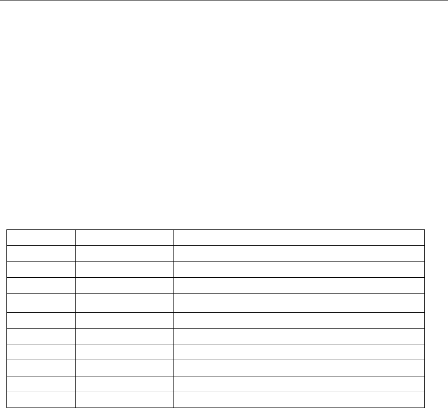
<parameter >:= {a parameter from the table below}
Parameters Value Description
ON --- Turn on
OFF --- Turn off
LOAD <load> Value of load (
default unit is ohm
)
PLRT <NOR, INVT> Value of polarity
parameter
< load>:= {please see the note below.}
QUERY SYNTAX <channel>: OUTP(OUTPut)?
RESPONSE FORMAT <channel>: OUTP <load>
EXAMPLE Turn on channel one.
C1: OUTP ON
Read channel one output state.
C1: OUTP?
Return:
C1: OUTP ON, LOAD, HZ, PLRT, NOR
Set the load to 50.
C1: OUTP LOAD, 50
Set the load to HZ.
C1: OUTP LOAD, HZ
Set the polarity normal.
C1: OUTP PLRT, NOR
Set the polarity inverted.

10
C1: OUTP PLRT, INVT
1.5. Basic Wave Command
DESCRIPTION Set or get basic wave parameters. If Wave Combine is turned on, it is
not possible to set the wave to square because combining a square
waveform is not possible.
COMMAND SYNTAX <channel>:BaSic_WaVe <parameter>
<channel>:={C1, C2}
<parameter>:= {a parameter from the table below}
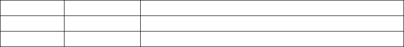
Parameters Value Description
WVTP <type> Type of wave
FRQ <frequency> Value of frequency. If wave type is Noise
or DC, you can’t set this parameter.
PERI <period>
Value of period. If wave type is Noise or DC,
you can’t set this parameter.
AMP <amplitude> Value of amplitude. If wave type is Noise
or DC, you can’t set this parameter.
OFST <offset> Value of offset. If wave type is Noise or D
C, you can’t set this parameter.
SYM <symmetry>
Value of symmetry. Only when wave type is
Ramp, you can set this parameter.
DUTY <duty> Value o
f duty cycle. Only when wave type is
Square and Pulse, you can set this parameter.
PHSE <phase> Value of phase. If wave type is Noise or P
ulse or DC, you can’t set this parameter.
STDEV <standard
deviation >
Value of Noise wave standard deviation. Only
w
hen wave type is Noise, you can set this
parameter.
MEAN <mean>
Value of Noise wave mean. Only when wave
type is Noise, you can set this parameter.
Note: if the command doesn’t set basic wave type, the parameter will set parameters to
current device wave type by default.
where: <type>:={SINE, SQUARE, RAMP, PULSE, NOISE, ARB ,DC}
<frequency>:= {Default unit is "Hz". Value depends on the model.}
<amplitude>:= {Default unit is "V". Value depends on the model.}

11
<offset>:= {Default unit is "V". Value depends on the model.}
<duty>:= {0% to 100%. Value depends on frequency.}
<symmetry> :={ 0% to 100%}
<phase>:= {0 to 360,if you set 400,it will set 40 (400-360)}
< standard deviation >:= {Default unit is "V". Value depends on the model.}
<mean>:= {Default unit is "V". Value depends on the model.}
<width>:= {Max_width < (Max_duty * 0.01) * period and Min_width >
(Min_duty * 0.01) * period.}
<rise>:= {Value depends on the model.}
<fall>:= {Value depends on the model.}
<delay>:= {Unit is S. Maximal is Pulse period, minimum value is 0.}
<bandwidth switch >:= {ON,OFF}
<bandwidth value>:= {value between 20MHz and 120MHz}
QUERY SYNTAX <channel>: BaSic_WaVe?
<channel>:={C1, C2}
RESPONSE <channel>:BSWV<type>,<frequency>,<amplitude>,<offset>,<duty>,
<symmetry>, <phase>,<variance>,<mean>,<width>, <rise>, <fall>, <delay>.
EXAMPLE 1 change channel one current wave type to ramp.
C1:BSWV WVTP,RAMP
EXAMPLE 2 Changes current signal frequency of channel one to 2000 Hz.
C1: BSWV FRQ, 2000
EXAMPLE 3 set current signal amplifier of channel one.
C1: BSWV AMP, 3
EXAMPLE 4 reads channel basic wave parameters from device.
C1:BSWV?
Return:
C1:BSWV WVTP, SINE,FRQ,100HZ,PERI,0.01S,AMP,2V, OFST,0V,HLEV,1V,
LLEV,-1V,PHSE,0
RELATED COMMANDS ARWV, BTWV, CFG, CPL, MDWV, SWWV
1.6. Arbitrary Wave Command
DESCRIPTION Sets and gets arbitrary wave type.

12
COMMAND SYNTAX <channel>:ArbWaVe INDEX,<value1>
<channel>:ArbWaVe NAME,<value2>
<channel>:={C1, C2}
<value1>: the table below shows what the index number and its
corresponding waveform name.
< value2>: For user-defined waveforms, this is the name of the waveform.
It is case-sensitive.
Index
Name
Index
Name
Index
Name
Index
Name
0 StairUp 50 RoundHalf 100 LFPulse 150 SquareDuty16
1 StairDn 51 RoundsPM 101 Tens1 151 SquareDuty18
2 StarUD 52 BlaseiWave 102 Tens2 152 SquareDuty20
3 Ppulse 53 DampedOsc 103 Tens3 153 SquareDuty22
4 Npulse 54 SwingOsc 104 Airy 154 SquareDuty24
5 Trepezia 55 Discharge 105 Besselj 155 SquareDuty26
6
Upramp
56
Pahcur
106
Bessely
156
SquareDuty28
7
Dnramp
57
Combin
107
Dirichlet
157
SquareDuty30
8
ExpFal
58
SCR
108
Erf
158
SquareDuty32
9
ExpRise
59
Butterworth
109
Erfc
159
SquareDuty34
10 LogFall 60 Chebyshev1 110 ErfcInv 160 SquareDuty36
11 LogRise 61 Chebyshev2 111 ErfInv 161 SquareDuty38
12 Sqrt 62 TV 112 Laguerre 162 SquareDuty40
13 Root3 63 Voice 113 Legend 163 SquareDuty42
14 X^2 64 Surge 114 Versiera 164 SquareDuty44
15
X^3
65
Radar
115
Weibull
165
SquareDuty46
16
Sinc
66
Ripple
116
LogNormal
166
SquareDuty48
17
Gaussian
67
Gamma
117
Laplace
167
SquareDuty50
18
Dlorentz
68
StepResp
118
Maxwell
168
SquareDuty52
19
Haversine
69
BandLimited
119
Rayleigh
169
SquareDuty54
20 Lorentz 70 CPulse 120 Cauchy 170 SquareDuty56
21 Gauspuls 71 CWPulse 121 CosH 171 SquareDuty58
22 Gmonopuls 72 GateVibr 122 CosInt 172 SquareDuty60
23 Tripuls 73 LFMPulse 123 CotH 173 SquareDuty62
24 Cardiac 74 MCNoise 124 CscH 174 SquareDuty64
25 Quake 75 AM 125 SecH 175 SquareDuty66
26
Chirp
76
FM
126
SinH
176
SquareDuty68
27
Twotone
77
PFM
127
SinInt
177
SquareDuty70
28
SNR
78
PM
128
TanH
178
SquareDuty72
29
Hamming
79
PWM
129
ACosH
179
SquareDuty74
30 Hanning 80 EOG 130 ASecH 180 SquareDuty76
31 Kaiser 81 EEG 131 ASinH 181 SquareDuty78
32 Blackman 82 EMG 132 ATanH 182 SquareDuty80
33 Gausswin 83 Pulseilogram 133 ACscH 183 SquareDuty82

13
34 Triangle 84 ResSpeed 134 ACotH 184 SquareDuty84
35 BlackmanH 85 ECG1 135 Bartlett 185 SquareDuty86
36 Bartlett-Ha
nn
86 ECG2 136 BohmanWin 186 SquareDuty88
37 Tan 87 ECG3 137 ChebWin 187 SquareDuty90
38 Cot 88 ECG4 138 FlattopWin 188 SquareDuty92
39 Sec 89 ECG5 139 ParzenWin 189 SquareDuty94
40 Csc 90 ECG6 140 TaylorWin 190 SquareDuty96
41 Asin 91 ECG7 141 TukeyWin 191 SquareDuty98
42 Acos 92 ECG8 142 SquareDuty01 192 SquareDuty99
43
Atan
93
ECG9
143
SquareDuty02
193
demo1_375pts
44
Acot
94
ECG10
144
SquareDuty04
194
demo1_16kpts
45
Square
95
ECG11
145
SquareDuty06
195
demo2_3kpts
46
SinTra
96
ECG12
146
SquareDuty08
196
demo2_16kpts
47 SineVer 97 ECG13 147 SquareDuty10
48 AmpALT 98 ECG14 148 SquareDuty12
49 AttALT 99 ECG15 149 SquareDuty14
Note: Index is only available for built-in waves and Name is only available for user defined
wave.
QUERY SYNTAX <channel>:ARWV (ARbWaVe)?
<channel>:={C1, C2}
RESPONSE FORMAT <channel>:ARWV <index>
EXAMPLE 1 Set StarUp arbitrary wave output by index.
ARWV INDEX, 2
EXAMPLE 2 Reads system current wave.
ARWV?
Return:
ARWV INDEX,2,NAME,stairup
EXAMPLE 3 Set Atan arbitrary wave output by name.
ARWV NAME, ATAN
RELATED COMMANDS BSWV
1.7. Modulate Wave Command
DESCRIPTION Set or get modulated wave parameters.

14
COMMAND SYNTAX <channel>:MoDulateWaVe<parameter>
<channel>:={C1, C2}
<parameter>:= {a parameter from the table below. }
Parameters Value Description
STATE <state> Turn on or off modulation. Note: if you want to
set or read other parameters of modulation, you
must set STATE to ON at first.
AM, SRC <src> AM signal source.
AM, MDSP <mod wave shape> AM modulation wave. Only when AM signal
source is set to INT, you can set the param
eter.
AM, FRQ <AM frequency> AM frequency. Only when AM signal source
is set to INT, you can set the parameter.
AM, DEPTH <depth> AM depth. Only when AM signal source is set to
INT, you can set the parameter.
DSBAM, SRC <src> DSBAM signal source.
DSBAM, MDSP <mod wave shape> DSBAM modulation wave. Only when AM signal
source is set to INT, you can set the parameter.
DSBAM, FRQ <DSB-AM frequency> DSBAM frequency. Only when AM signal source
is set to INT, you can set the parameter.
FM, SRC <src> FM signal source.
FM, MDSP <mod wave shape>
FM modulation wave. Only when FM signal
source is set to INT, you can set the parameter.
FM, FRQ <FM frequency> FM frequency. Only when FM signal source is set
to INT, you can set the parameter.
FM, DEVI
<FM frequency
deviation >
FM frequency deviation. Only when FM signal
source is set to INT. you can set the parameter.
PM, SRC, <src> PM signal source.
PM, MDSP <mod wave shape> PM modulation wave. Only when PM signal
source is set to INT, you can set the parameter.
PM, FRQ <PM frequency> PM frequency. Only when PM signal source is set
to INT, you can set the parameter.
PWM, FRQ <PWM frequency>
PWM frequency. Only when carrier wave is
PULSE wave, you can set the parameter.
PWM, DEVI <PWM dev> Duty cycle deviation. Only when carrier wave is
PULSE wave, you can set the parameter.
PWM, MDSP <mod wave shape> PWM modulation wave. Only when carrier wave
is PULSE wave, you can set the parameter.
PWM, SRC <src> PWM signal source.
PM, DEVI <PM phase offset>
PM phase deviation. Only when PM signal
source is set to INT, you can set the parameter.
ASK, SRC <src> ASK signal source.

15
ASK, KFRQ <ASK key frequency>
ASK key frequency. Only when ASK signal source
is set to INT, you can set the parameter.
FSK, KFRQ <FSK key frequency> FSK key frequency. Only when FSK signal source
is set to INT, you can set the parameter.
FSK, HFRQ <FSK hop frequency> FSK hop frequency.
FSK, SRC <src> FSK signal source.
PSK, KFRQ <FSK key frequency> PSK key frequency. Only when PSK signal source
is set to INT, you can set the parameter.
PSK, SRC <src> PSK signal source.
CARR, WVTP <wave type> Carrier wave type.
CARR, FRQ <frequency> Value of carrier frequency.
CARR, AMP <amplitude> Value of carrier amplitude.
CARR, OFST <offset> Value of carrier offset.
CARR, SYM <symmetry>
Value of carrier symmetry. Only ramp can set this
parameter.
CARR, DUTY <duty>
Value of duty cycle. Only square and pulse can
set this parameter.
CARR, PHSE <phase> Value of carrier phase.
CARR, RISE <rise>
Value of rise time. Only Pulse can set this
parameter.
CARR, FALL <fall>
Value of fall time. Only Pulse can set this
parameter.
CARR, DLY <delay> Value of carrier delay. Only PULSE can set this
parameter.
Note: If Carrier wave is Pulse or Noise, the modulation waveform cannot be set. To set AM,
FM, PM, CARR and STATE the first parameter have to be one of them.
where: <state>:={ON,OFF}
<src>:= {INT,EXT}
<mod wave shape>:={SINE, SQUARE, TRIANGLE, UP RAMP, DNRAMP, NOISE,
ARB}
<am frequency>:= {Default unit is "Hz". Value depends on model}
<depth>:= {0% to 120%}
<fm frequency>:= {Default unit is "Hz". Value depends on model)
<fm frequency deviation > :={ 0 to carrier frequency, Value depends on the
difference between carrier frequency and bandwidth frequency.}
<pm frequency> :={Default units are in “Hz”. Value depends on
model}
<pm phase offset>:= {0° to 360°}
<pwm frequency>:= {0Hz to 4kHz }
<pwm dev>:= { Default unit is "%",value depends on carrier duty cycle}
<ask key frequency>:= Default units are in “Hz”. Value depends on
16
model}
<fsk frequency>:={Default units are in “Hz”. Value depends on
model}
<fsk jump frequency>:= { the same witch basic wave frequency}
<wave type>:={SINE ,SQUARE, RAMP, ARB, PULSE }
<frequency>:= { Default units are in “Hz”. Value depends on model}
<amplitude>:={Default units are in “Volts”. Value depends on model}
<offset>:={ Default unit is "V".}
<duty>:={0% to 100 %.}
<symmetry>:={ 0% to 100%}
<rise>:= {Value depends on the model.}
<fall>:= {Value depends on the model.}
<delay>:= {Default unit is "S".}
QUERY SYNTAX <channel>:MoDulateWaVe?
<channel>:={C1, C2}
RESPONSE FORMAT <channel>:MoDulateWaVe <parameter>
<parameter>:={return all parameter of the current modulation wave
parameters.}
EXAMPLE 1 Set channel one modulation type to AM.
C1:MDWV AM
EXAMPLE 2 Set modulation shape to AM, and set AM modulating wave shape to
sine wave.
C1:MDWV AM, MDSP, SINE
EXAMPLE 3 Reads channel one modulate wave parameters that STATE is ON.
C1:MDWV?
Return:
C1:MDWV
STATE,ON,AM,MDSP,SINE,SRC,INT,FRQ,100HZ,DEPTH,100,CARR,WVTP
,RAMP,FRQ,1000HZ,AMP,4V,OFST,0V,SYM,50
EXAMPLE 4 Reads channel one modulate wave parameters that STATE is OFF.
C1:MDWV?
Return:
C1:MDWV STATE,OFF
EXAMPLE 5 Set channel one Fm frequency to 1000HZ
C1:MDWV FM, FRQ, 1000HZ

17
EXAMPLE 6 Set the value of channel one carrier wave shape to SINE.
C1:MDWV CARR,WVTP,SINE
EXAMPLE 7 Set the Value of channel one carrier wave frequency to 1000Hz.
C1:MDWV CARR,FRQ,1000
RELATED COMMANDS ARWV, BTWV, SWWV, BSWV
1.8. Sweep Wave Command
DESCRIPTION Set or get sweep wave parameters.
COMMAND SYNTAX <channel>: SWeepWaVe) <parameter>
<channel>:={C1, C2}
<parameter>:= {a parameter from the table below. }
Parameters Value Description
STATE <state> Turn on or off sweep wave. Note if you want to set or read
sweep wave parameters, you must first
enable sweep
mode.
TIME <time> Value of sweep time
STOP <stop frequency> Value of stop frequency
START <start frequency> Value of start frequency
TRSR <trigger src> Trigger source
TRMD <trigger mode> Value of trigger output. If TRSR is EXT,
the parameter is
invalid.
SWMD <sweep mode > Sweep way
DIR
<direction>
Sweep direction
EDGE <edge> Value of edge. Only TRSR is EXT, the parameter is valid.
MTRIG <manual trigger> Make the device once manual trigger.
The parameter is
valid only when TRSR is set to MAN.
CARR,WVTP <wave type> Value of carrier wave type.
CARR,FRQ
<frequency>
Value of frequency.
CARR,AMP <amplifier> Value of amplifier.
CARR,OFST <offset> Value of offset.
CARR,SYM <symmetry> Value of symmetry.
CARR,DUTY <duty> Value of duty cycle.
Only Square can set this parameter.
CARR,PHSE <phase> Value of phase.
Note: If Carrier wave is Pulse or Noise, enabling sweep is not allowed. If you want to set
18
CARR and STATE, the first parameter has to be one of them.
where: <state>:= {ON, OFF}
<time>:= { Default unit is "S". Value depends on the model.}
<stop frequency> :={ the same with basic wave frequency}
<start frequency> :={ the same with basic wave frequency}
<trigger src>:= {EXT, INT, MAN}
<trigger mode>:= {ON, OFF}
<sweep mod>:= {LINE, LOG}
<direction>:= {UP, DOWN}
<edge>:={RISE, FALL}
<wave type>:={SINE ,SQUARE, RAMP, ARB}
<frequency> :={ Default unit is "Hz". Value depends on the model.}
<amplitude> :={ Default unit is "V". Value depends on the model.}
<offset> :={ Default unit is "V", Value depends on the model.}
<duty>:= {0% to 100 %.}
<symmetry>:={ 0% to 100%}
QUERY SYNTAX <channel>:SWeepWaVe?
<channel>:={C1, C2}
RESPONSE FORMAT <parameter>:={return all parameter of the current sweep wave
parameters.}
EXAMPLE 1 Set channel one sweep time to 1 S.
C1:SWWV TIME, 1S
EXAMPLE 2 Set channel one sweep stop frequency to 1000hz.
C1: SWWV STOP, 1000HZ
EXAMPLE 3 Read channel one sweep parameters of which STATE is ON.
C2: SWWV?
Return:
C2: SWWV STATE, ON, TIME, 1S, STOP, 100HZ, START, 100HZ, TRSR,
MAN,TRMD, OFF, SWMD, LINE, DIR, UP, CARR, WVTP, SQUARE,
FRQ, 1000HZ, AMP, 4V, OFST, 0V, DUTY, 50, PHSE, 0
EXAMPLE 4 Reads channel two modulate wave parameters that STATE is OFF.
C2:SWWV?
Return:
C2:SWWV STATE,OFF

19
1.9. Burst Wave Command
DESCRIPTION Set or get burst wave parameters.
COMMAND SYNTAX <channel>:BursTWaVe <parameter>
<channel>:={C1, C2}
<parameter>:= {a parameter from the table below.}
Parameters Value Description
STATE <state> Enable or disable
burst wave. Note if
you want to se
t or read burst wave
parameters
you must first enable burst
mode.
PRD <period> When carrier wave is NOISE wave, this
cannot be set. When GATE is selected,
you cannot set this. This can be set only
when trig source is IN (internal).
STPS <start phase>
When carrier wave is NOISE or PULSE
wave, you can’t set it.
GATE_NCYC <gate ncycle> When carrier wave is NOISE, you can’t
set it.
TRSR <trigger> When carrier wave is NOISE wave, you
can’t set it. When NCYC was chosen you
can set it.
DLAY <delay> When carrier wave is NOISE wave, you
can’t set it. When NCYC was chosen you
can’t set it.
PLRT <polarity> When GATE was chosen you can set it.
When carrier wave is NOISE,
it is the
only parameter.
TRMD <trig mode> When carrier wave is NOISE wave, you
can’t set it. When NCYC was chosen you
can set it. When TRSR is set to EXT, you
can’t set is.
EDGE <edge> When carrier wave is NOISE wave, you
can’t set it. When NCYC is selected and
TRSR is set to EXT, you can set it.
TIME <circle time> When carrier wave is NOISE wave, you
can’t set it. When NCYC is selected, you
can set it.
MTRIG
When TRSR’s parameter be chosen to

20
MAN, that it can be set.
CARR,WVTP <wave type> Value of carrier wave type.
CARR,FRQ <frequency> Value of frequency.
CARR,AMP <amplifier> Value of amplifier.
CARR,OFST <offset> Value of offset.
CARR,SYM <symmetry> Value of symmetry.
CARR,DUTY <duty> Value of duty cycle.
Only Square can set this parameter.
CARR,PHSE <phase> Value of phase.
CARR, RISE <rise> Value of rise edge. Only when carrier is Pulse,
the Value is valid.
CARR, FALL <fall> Value of fall edge. Only when carrier is Pulse,
the Value is valid.
CARR, STDEV <standard
deviation > Value of standard deviation. Only when
carrier is Noise, the Value is valid.
CARR,DLY <carr delay>
Value of carrier wave delay. This is valid
only when the carrier wave is pulse.
CARR, MEAN <mean> Value of carrier wave mean. This is valid
only when the carrier wave is noise.
Note: If you want to set CARR and STATE, the first parameter has to one of them
where: <state>:= {ON, OFF}
<period>:= {Default unit is “S”. Value depends on the model.}
<start phase>:= {0 to 360}
<gate ncycle>:= {GATE, NCYC}
<trigger source>:= {EXT, INT, MAN}
<delay>:= {Default unit is "S", Value depends on the model.}
<polarity>:= {NEG, POS}
<trig mode >:= {RISE, FALL, OFF}
<edge>:= { RISE, FALL}
<circle time> :={ Value depends on the Model (“INF” means infinite).}
<wave type>:={SINE ,SQUARE, RAMP, PULSE, NOISE, ARB}
<frequency> :={ Default unit is "HZ". Value depends on the model.}
<amplitude>:= {Default unit is "V". Value depends on the model.}
<offset>:= {Default unit is "V". Value depends on the model.}
<duty>:= {0% to 100%.}
<symmetry> :={ 0% to 100%}
<phase>:= {0 to 360}
< standard deviation >:= {Default unit is "V". Value depends on the
model.}
<mean>:= {Default unit is "V". Value depends on the model.}
<width> :={ Max_width < (Max_duty * 0.01) * period and Min_width >
(Min_duty * 0.01) * period.}
<rise>:= {Value depends on the model.}

21
<fall>:= {Value depends on the model.}
<delay>:= {Default unit is “S”.}
QUERY SYNTAX <channel>:BursTWaVe? <parameter>
<parameter>:=<period>……
RESPONSE FORMAT <channel>:BTWV <type>|<state>|<period>……
EXAMPLE 1 Set channel one burst wave period to 1S.
C1:BTWV PRD, 1
EXAMPLE 2 Set channel one burst wave delay to 0S
C1:BTWV DLAY, 0
EXAMPLE 3 Reads burst wave parameters of channel two when STATE is ON.
C2: BTWV?
Return:
C2:BTWV
STATE,ON,PRD,0.01S,STPS,0,TRSR,INT,TRMD,OFF,TIME,1,DLAY,2.4e-07
S,,GATE_NCYC,NCYC,CARR,WVTP,SINE,FRQ,1000HZ,AMP,4V,OFST,0V,P
HSE,0
EXAMPLE 4 Reads burst wave parameters of channel two when STATE is OFF.
C2: BTWV?
Return:
C2: BTWV STATE,OFF
22
1.10. Parameter Copy Command
DESCRIPTION Copies parameters from one channel to another.
COMMAND SYNTAX PAraCoPy <destination channel>, <src channel>
<destination channel>:= {C1, C2}
<src channle>:= {C1, C2}
Note: the parameters C1 and C2 must be set to device together.
EXAMPLE 1 Copy parameters from channel one to channel two.
PACP C2,C1
RELATED COMMANDS ARWV, BTWV, MDWV, SWWV, BSWV
1.11. Sync Command
DESCRIPTION Set signal output from rear panel in phase with forward.
COMMAND SYNTAX <channel>:SYNC <parameter>
<channel>:={C1,C2}
<parameter>:= {ON,OFF}
QUERY SYNTAX <channel>:SYNC?
RESPONSE FORMAT <channel>:SYNC <parameter>
EXAMPLE 1 Turn on sync function of channel one.
C1:SYNC ON
EXAMPLE 2 Reads channel one sync state.
C1:SYNC?
Return:
C1:SYNC OFF

23
1.12. Number Format Command
DESCRIPTION Sets or gets number format.
COMMAND SYNTAX NumBer_ForMat <parameter>
<parameter> :={ a parameter from the table below.}
Parameters Value Description
PNT <pnt> Point format
SEPT <sept> Separator format
Where:
<pnt>:= {Dot, Comma}.
<sept> :={ Space, Off, On}.
QUERY SYNTAX NumBer_ForMat?
RESPONSE FORMAT NBFM <parameter>
EXAMPLE 1 Set point format to DOT.
NBFM PNT, DOT
EXAMPLE 2 Set Separator format to ON.
NBFM SEPT,ON
EXAMPLE 3 Read number format.
NBFM?
Return:
NBFM PNT, DOT, SEPT, ON
1.13. Configuration Command
DESCRIPTION Changes system load data of power on.
COMMAND SYNTAX Sys_CFG<parameter>
<parameter>:= {DEFAULT,LAST}
QUERY SYNTAX Sys_CFG?
RESPONSE FORMAT SCFG <parameter>
EXAMPLE 1 Set system load data of power on to last time data.
SCFG LAST
24
1.14. Buzzer Command
DESCRIPTION Turns on or off buzzer.
COMMAND SYNTAX BUZZer <parameter>
<parameter>:= {ON,OFF}
QUERY SYNTAX BUZZer?
RESPONSE FORMAT BUZZ <parameter>
EXAMPLE 1 Turns on buzzer.
BUZZ ON
1.15. Screen Save Command
DESCRIPTION Turns on or off Screen Save.
COMMAND SYNTAX SCreen_SaVe <parameter>
<parameter>:= {OFF,1,5,15,30,60,120,300, Units are minutes}
QUERY SYNTAX SCreen_SaVe?
RESPONSE FORMAT SCSV <parameter>
EXAMPLE 1 Set screen save time 5 minutes.
SCSV 5
1.16. Clock Source Command
DESCRIPTION Set or get signal oscillator resource.
COMMAND SYNTAX ROSCillator <parameter>
<parameter>:= {INT, EXT }
QUERY SYNTAX ROSCillator?
25
RESPONSE FORMAT ROSC <parameter>
EXAMPLE 1 Uses system clock source.
ROSC INT
1.17. Frequency Counter Command
DESCRIPTION Sets or gets frequency counter parameters.
COMMAND SYNTAX FreqCouNTer <parameter>
<parameter>:= {a parameter from the table below}
Parameters Value Description
STATE <state> State of frequency counter.
FRQ <frequency> Value of frequency. Can’t be set.
PW <position width> Value of positive width. Can’t be set.
NW <negative width> Value of negative width. Can’t be set.
DUTY <duty> Value of duty cycle. Can’t be set.
FRQDEV <freq deviation> Value of freq deviation. Can’t be set.
REFQ <ref freq> Value of reference freq.
TRG <triglev> Value of trigger level.
MODE <mode> Value of mode.
HFR <HFR> State of HFR.
where: < state >:={ON, OFF}
<frequency>:= {Default unit is "Hz". Value range depends on the model.}
< mode >:={AC, DC}
<HFR>:={ON, OFF}
QUERY SYNTAX FreqCouNTer?
RESPONSE FORMAT FCNT < state ><frequency><duty><ref freq><triglev><position width><
negative width>
<freq deviation><mode><HFR>
EXAMPLE 1
Turn frequency counter on:
FCNT STATE,ON
EXAMPLE 2
Set reference freq to 1000Hz:
FCNT REFQ,1000
EXAMPLE 3
26
Query frequency counter information:
FCNT?
Return:
FCNT STATE,ON,FRQ,10000000HZ,DUTY,59.8568,REFQ,
1e+07HZ,TRG,0V,PW,5.98568e-08S,NW,4.01432e-08S,FRQDEV,0ppm,MODE,
AC,HFR,OFF
1.18. Invert Command
DESCRIPTION Sets or gets polarity of current channel.
COMMAND SYNTAX <channel>:INVerT <parameter>
<channel>:={C1, C2}
<parameter>:= {ON, OFF}
QUERY SYNTAX <channel>: INVT (INVerT)?
<channel>:={C1, C2}
RESPONSE FORMAT <channel>:INVerT <parameter>
EXAMPLE 1
Set C1 ON:
C1: INVT ON
EXAMPLE 2
Read the polarity of channel one.
C1: INVT?
Return:
C1: INVT ON
Note: The <channel> is a selectable parameter. If channel is not set, default is current
channel.
1.19 Coupling Command
DESCRIPTION Sets or gets channel coupling parameters. You can only set coupling
value when trace switch off.
COMMAND SYNTAX COUPling <parameter>
<parameter>:= {a parameter from the table below}
Parameters
Value
Description
TRACE <trace> Trace switch
FDEV <frq_dev> Value of f frequency deviation.

27
PDEV <pha_dev> Value of position phase deviation.
FCOUP <fcoup> Value of frequency coupling switch
FRAT <frat> Value of frequency coupling ratio
PCOUP <pcoup> Value of phase coupling switch
PRAT <prat> Value of phase coupling ratio
ACOUP <acoup> Value of amplitude coupling switch
ARAT <arat> Value of amplitude coupling ratio
ADEV <adev> Value of amplitude coupling deviation
where: <trace>:={ON, OFF}
< state >:={ON, OFF}
< bsch >:= {CH1, CH2}
< frq_dev >:={ Default unit is “Hz”, value range depends on the model}
< pha_dev >:={ Default unit is “°”value range depends on the model }
<fcoup>,<acoup>,<pcoup>:={ON, OFF}
<frat>,<prat>,< arat >:={a ratio value. value range depends on the model }
<adev>:={ a deviation value. value range depends on the model }
QUERY SYNTAX
EXAMPLE 1
EXAMPLE 2
EXAMPLE 3
EXAMPLE 4
COUPling?
Set 4050B coupling state on
COUP STATE,ON
Set 4050B frequency deviation value 5Hz
COUP FDEV,5
Set 4050B amplitude coupling ratio
COUP ARAT,2
Query 4050B coupling information.
COUP?
Return:
COUP\sTRACE,OFF,FCOUP,ON,PCOUP,ON,ACOUP,ON,FDEV,5HZ,
PRAT,1,ARAT,2\n
1.20 Voltage Overload Command
DESCRIPTION Sets or gets state of over-voltage protection.
COMMAND SYNTAX VOLTPRT <parameter>
<parameter>:= {ON, OFF}
28
QUERY SYNTAX VOLTPRT?
RESPONSE FORMAT VOLTPRT <parameter>
1.21 Store list command
DESCRIPTION This command is used to read the device wave data name. If the
store unit is empty, the command will return an “EMPTY” string.
QUERY SYNTAX StoreList? BUILDIN, USER
RESPONSE FORMAT STL M0, SINE, M1, noise, M2, STAIRUP….
EXAMPLE 1 Read device memory saved arbitrary data.
STL?
Return:
STL M0, SINE, M1, noise, M2, STAIRUP….
EXAMPLE 2 Read built-in wave data.
STL? BUILDIN
Return:
STL M0, Sine, M1, Noise, M10, ExpFal, M11, ExpRise….
EXAMPLE 3 Read wave data defined by user.
STL? USER
Return:
STL
WVNM,sinec_8M,sinec_3000000,sinec_1664000,ramp_8M,sinec_2000000
,sinec_50000,square_8M,sinec_5000,wave1,square_1M
1.22 Get arbitrary wave data command
DESCRIPTION This command changes the user defined memory unit arbitrary wave
data.
COMMAND SYNTAX WaVe_DaTa <address>,<parameter>
<channel>:={C1, C2}
<address>:= {M0-M196}
29
<parameter>:= {a parameter from the table below. }
Note: All parameters must be set in one command. If not, the command will not execute
successfully.
QUERY SYNTAX For built-in waves
WVDT? Mn (x=0-196)
Where:(0<=n<=196):
M0~M196: all of them are building in waves (32KB). User defined waves do
not have this index.
For user defined waves
WVDT? USER,<wave name>
<wave name>:={The name of user defined wave}
RESPONSE FORMAT WaVe_DaTa <parameter>
EXAMPLE Read device memory saved arbitrary data.
WVDT? M50
return:
WVDT\sPOS,\sM2,\sWVNM,\sStairUD,\sLENGTH,\s32768B,\sTYPE,
\s6,\sWAVEDATA,\FF\7F\FF\7F\FF\7F\FF\7F\FF\7F\FF\7F\FF\7F\FF\7
F\FF\7F\FF\7F\FF\7F\FF\7F\FF\7F\FF\7F\FF\7F\FF\7F\FF\7F\FF\7F\F
F\7F\FF\7F\FF\7F\FF\7F\FF\7F\FF\7F\FF\7F\FF\7F\FF\7F\FF\7F\FF\7
F\FF\7F\FF\7F\FF\7F\FF\7F\FF\7F\FF\7F\FF\7F\FF\7F\FF\7F\FF\7F\F
F\7F\FF\7F\FF\7F\FF\7F\FF\7F\FF\7F\FF\7F\FF\7F\FF\7F\FF\7F\FF\7
F\FF\7F\FF\7F\FF\7F\FF\7F\FF\7F\FF\7F\FF\7F\FF\7F\FF\7F\FF\7F\F
F\7F\FF\7F\FF\7F\FF\7F\FF\7F\FF\7F\FF\7F\FF\7F\FF\7F\FF\7F\FF\7
F\FF\7F\FF\7F\FF\7F\FF\7F\FF\7F\FF\7F\FF\7F\FF\7F\FF\7F\FF\7F\F
F\7F\FF\7F\FF\7F\FF\7F\FF\7F\FF\7F\FF\7F\FF\7F\FF\7F\FF\7F\FF\7
F\FF\7F\FF\7F\FF\7F\FF\7F\FF\7F\FF\7F\FF\7F\FF\7F\FF\7F\FF\7F\F
F\7F\FF\7F\FF\7F\FF\7F\FF\7F\FF\7F\FF\7F\FF\7F\FF\7F\FF\7F\FF\7
F\FF\7F\FF\7F\FF\7F\FF\7F\FF\7F\FF\7F\FF\7F\FF\7F\FF\7F\FF\7F\F
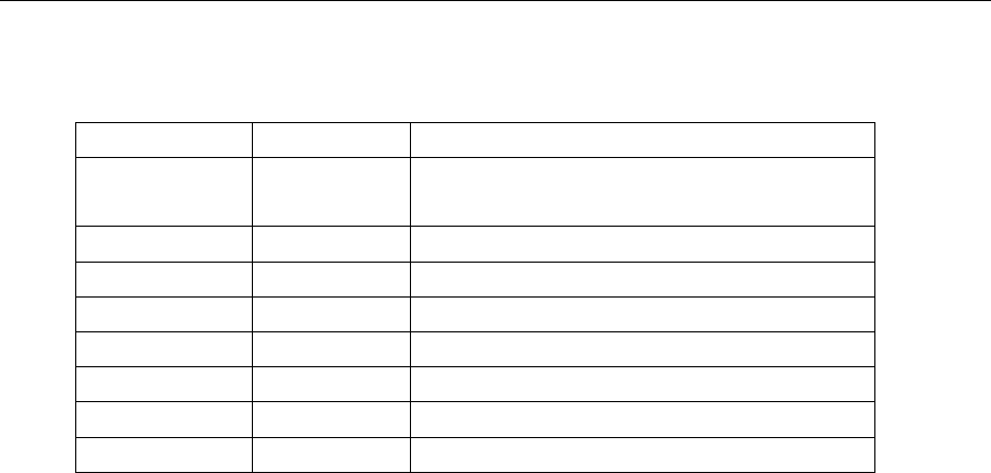
Parameters Value Description
WVNM <wave
name> Wave name.
TYPE <type> Wave type.
LENGTH
<length>
Wave length, FROM 8b~8M
FREQ <frequency> Wave frequency.
AMPL <amplifier> Wave amplifier.
OFST <offset> Wave offset.
PHASE <phase> Wave phase.
WAVEDATA <wave data> Wave data.
30
F\7F\FF\7F\FF\7F\FF\7F\FF\7F\FF\7F\FF\7F\FF\7F\FF\7F\FF\7F\FF\7
F\…

31
1.19. Virtual key command
DESCRIPTION The Command is used to send simulate a operation of pressing key on
front panel
COMMAND SYNTAX VKEY (VirtualKEY) VALUE,<value>,STATE,<state>
<value>:= {a parameter from the table below.}
<state>:=<0,1>( “1” is effective to virtual value, and “0” is useless )
EXAMPLE VKEY VALUE,15, STATE,1
VKEY VALUE,KB_SWEEP, STATE,1
KB_FUNC1 28 KB_NUMBER_4 52
KB_FUNC2 23 KB_NUMBER_5 53
KB_FUNC3 18 KB_NUMBER_6 54
KB_FUNC4
13
KB_NUMBER_7
55
KB_FUNC5 8 KB_NUMBER_8 56
KB_FUNC6 3 KB_NUMBER_9 57
KB_MOD 15 KB_POINT 46
KB_SWEEP 16 KB_NEGATIVE 43
KB_BURST 17 KB_LEFT 44
KB_WAVES 4 KB_RIGHT 40
KB_UTILITY 11 KB_OUTPUT1 153
KB_PARAMETER 5 KB_OUTPUT2 152
KB_STORE_RECALL 70 KB_KNOB_RIGHT 175
KB_NUMBER_0 48 KB_KNOB_LEFT 177
KB_NUMBER_1
49
KB_KNOB_DOWN
176
KB_NUMBER_2 50 KB_HELP 12
KB_NUMBER_3 51 KB_CHANNEL 72
1.20. Harmonic Command
DESCRIPTION Sets or gets harmonic information. The channel basic wave must
be sine.

32
COMMAND SYNTAX
<channel>:HARM(HARMonic) HARMSTATE,<value1>, HARMTYPE
, < value2>, HARMORDER,< value3>, <parameter>, <value4>,
HARMPHASE, < value5>
<value1>:= <ON, OFF>
<value2>:= <EVEN, ODD,ALL>
< value3>:= {an integer value.}
<parameter> :=< HARMAMP, HARMDBC>
< value4>:= {an integer value.}
< value5>:= {an integer value.}
QUERY SYNTAX <channel>: HARM (HARMonic)?
<channel>:={C1, C2}
EXAMPLES Set the channel one harmonic switch on.
C1: HARMHARMSTATE, ON
Get the channel one harmonic information.
C1: HARM?
Return:
C1:HARM HARMSTATE, ON,HARMTYPE, EVEN,HARMORDER, 2,
HARMAMP, 0V, HARMPHASE, 0
1.23 Waveform Combining Command
DESCRIPTION Sets or gets waveform combining information.
COMMAND SYNTAX <channel>: CoMBiNe <parameter>
<channel>:={C1, C2}
<parameter>:= {ON, OFF}
QUERY SYNTAX <channel>: CoMBiNe?
<channel>:={C1, C2}
EXAMPLES Turn on the waveform combining of channel one.

33
C1:CMBN ON
Query the waveform combining state of channel two.
C2:CMBN?
Return:
C2:CMBN OFF
1.24 IP Command
DESCRIPTION The Command can set and get system IP address.
COMMAND SYNTAX SYSTem:COMMunicate:LAN:IPADdress <parameter1>.<parameter2>.
<parameter3>.<parameter4>
Where:
<parameter1>:={a integer value between 1 and 223}
<parameter2>:={a integer value between 0 and 255}
<parameter3>:={a integer value between 0 and 255}
<parameter4>:={a integer value between 0 and 255}
QUERY SYNTAX SYSTem:COMMunicate:LAN:IPADdress?
EXAMPLES Set IP address to 10.11.13.203
SYSTem: COMMunicate: LAN:IPADdress 10.11.13.203
Get IP address.
SYST:COMM:LAN:IPAD?
Return:
“10.11.13.203”
1.25 Subnet Mask Command
DESCRIPTION The Command can set and get system subnet mask.
COMMAND SYNTAX SYSTem:COMMunicate:LAN:SMASk <parameter1>.<parameter2>.
<parameter3>.<parameter4>
34
Note:
<parameter1>:={a integer value between 0 and 255}
<parameter2>:={a integer value between 0 and 255}
<parameter3>:={a integer value between 0 and 255}
<parameter4>:={a integer value between 0 and 255}
QUERY SYNTAX SYSTem:COMMunicate:LAN:SMASk?
EXAMPLES Set subnet mask to 255.0.0.0
SYSTem:COMMunicate:LAN:SMASk 255.0.0.0
Get subnet mask
SYSTem:COMMunicate:LAN:SMASk?
Return:
“255.0.0.0”
1.26 Gateway Command
DESCRIPTION The Command can set and get system Gateway.
COMMAND SYNTAX SYST:COMM:LAN:GAT(SYSTem:COMMunicate:LAN:GATeway)
<parameter1>.<parameter2>.<parameter3>.<parameter4>
Note:
<parameter1>:={a integer value between 0 and 223}
<parameter2>:={a integer value between 0 and 255}
<parameter3>:={a integer value between 0 and 255}
<parameter4>:={a integer value between 0 and 255}
QUERY SYNTAX SYSTem:COMMunicate:LAN:GATeway?
EXAMPLES Set Gateway to 10.11.13.5:
SYSTem:COMMunicate:LAN:GATeway 10.11.13.5
Get gateway:
SYSTem:COMMunicate:LAN:GATeway?
Return:
“10.11.13.5”

V042413
1.27 Index
*IDN *IDN
*OPC *OPC
*CLS *CLS
*ESE *ESE
*ESR *ESR
*RST *RST
*SRE *SRE
*STB *STB
*TST *TST
A
ARWV ARBWAVE
B
BSWV BASIC_WAVE
BTWV BURSTWAVE
BUZZ BUZZER
C
CHCP CHANNEL_COPY
CHDR COMM_HEADER
CMBN CoMBiNe
COUP COUPLING
D
DCWV DC_WAVE
F
FCNT FREQCOUNTER
H
HARM HARMonic
I
INVT INVERT
M
MDWV MODULATEWAVE
N
NBFM NumBer_ForMat
O
OUTP OUTPUT
P
PACP PARACOPY
R
