BlackBerry R6420GN GPRS OEM Radio Modems 1902GS & 1902G User Manual integrator guide
BlackBerry Limited GPRS OEM Radio Modems 1902GS & 1902G integrator guide
UserManual.wiki
>
BlackBerry
>
R6420GN User Manual
>
user manual
Contents
1.
user manual
2.
modified integrators guide
user manual
Navigation menu
Upload a User Manual
Namespaces
Wiki Guide
HTML
PDF
Info
Views
User Manual
Discussion / Help
Navigation


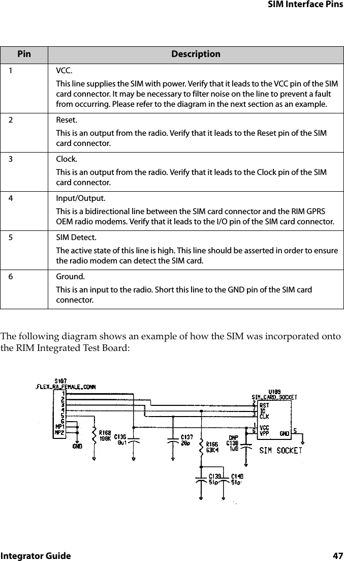
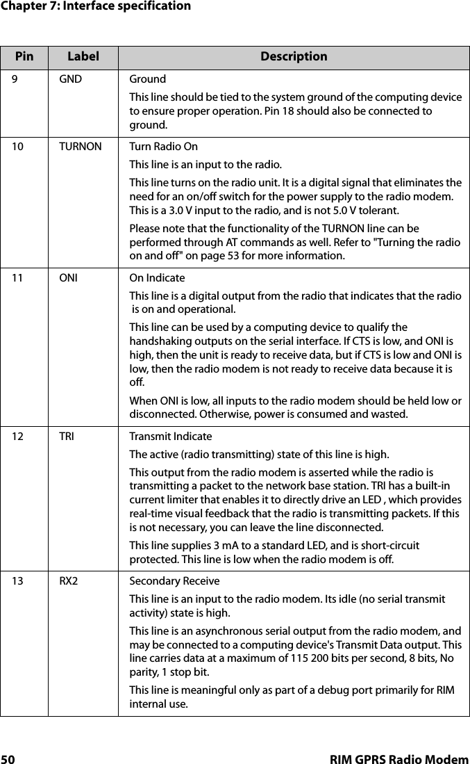
![Chapter 5: Integrating the radio modem34 RIM GPRS Radio Modem• SIM interface cable (G models only)• antenna connector Radio interface cable and connectorThe radio interface connector connects the radio modem to a serial computing device, speaker and microphone, and power supply. Serial communication data, control signals, and power are carried on a flat 22-conductor 0.30 mm (0.012 inches) thick flexible printed circuit (FPC) cable with 1-mm centerline spacing, which can plug into a matching connector. Because each application is unique, it may be necessary to create a custom Flat Flex Cable (FFC) Jumper with the correct length and correct connector orientation for your application. Please refer to the diagram in the next section for FPC specifications.The interface cable supplied with the Integrator’s Kit is a Type D 76.2 mm (3.0 inches) long FFC Jumper with 1 mm centerline spacing, Molex part number 210390382.This cable can plug into a matching 22-position 1.0 [0.039] horizontal FPC connector. AMP/Tyco Electronics manufactures a variety of connectors. For information about each connector, including mechanical drawings, visit the manufacturer’s web site (www.amp.com), or contact RIM (oemsupport@rim.net) for help selecting an appropriate connector for your application.SIM interface cable and connectorThe SIM interface cable and connector connects a SIM card to the radio modem. All SIM communication data and power are carried on a flat 6-conductor 0.30 mm (0.012") thick flexible printed circuit (FPC) cable with 1.00 mm centerline spacing, which can plug into a matching connector. Because each application is unique, it may be necessary to create a custom Flat Flex Cable Jumper with the correct length and connector orientation for your application. Please refer to the following diagram for FPC specifications:Note: The SIM interface cable and connector are only required for the 1902G and 1802G models.](https://usermanual.wiki/BlackBerry/R6420GN.user-manual/User-Guide-240920-Page-34.png)
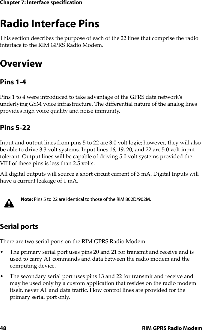
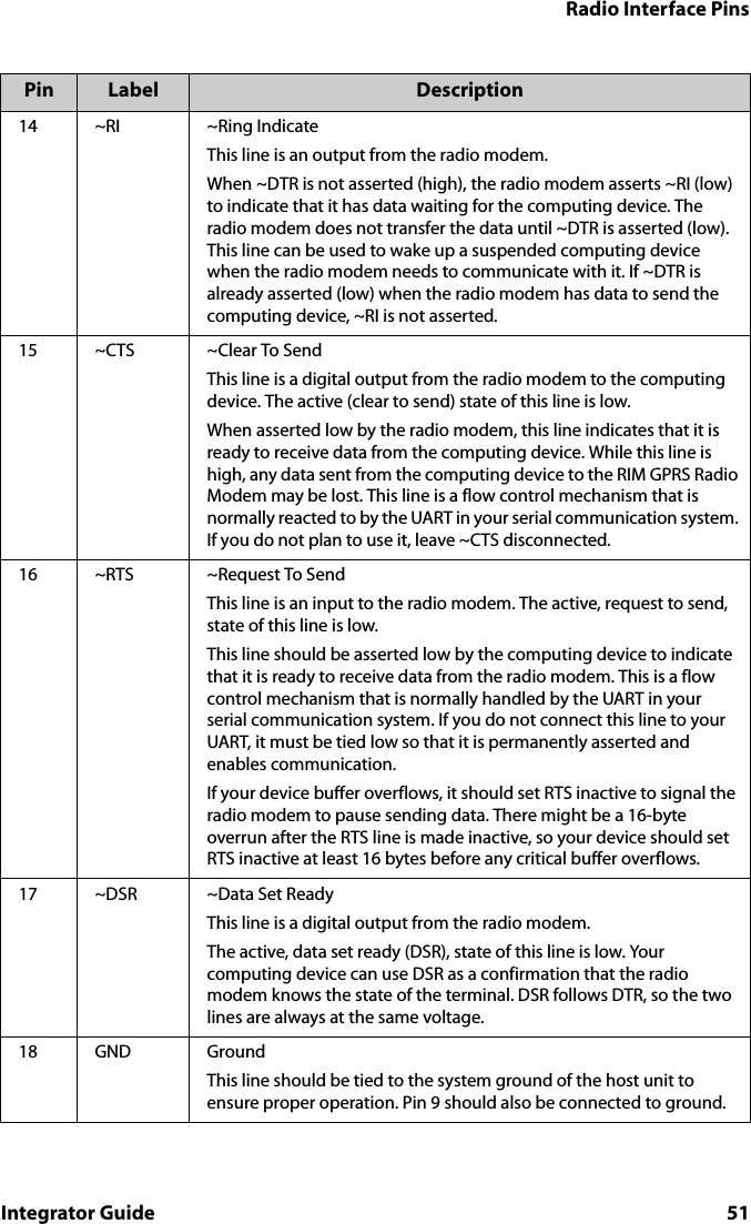
![Cables and connectorsIntegrator Guide 35The 6-pin interface cable supplied with the RIM GPRS Radio Modem Developer's Kit is a 76.2 mm (3.0") long Flat Flex Cable (FFC) Jumper with 1.00 mm centerline spacing and same side conductive surfaces, Parlex part number 100-6-76-B.This cable can plug into a matching 6-position 1.0 [0.039] horizontal FPC connector. A variety of connectors are manufactured by AMP/Tyco Electronics, including AMP part number 487951-6. For information about each connector, including mechanical drawings, visit the manufacturer's web site (www.amp.com), or contact RIM (oemsupport@rim.net) for help with selecting an appropriate connector for your application.](https://usermanual.wiki/BlackBerry/R6420GN.user-manual/User-Guide-240920-Page-35.png)