BlackBerry R6420GN GPRS OEM Radio Modems 1902GS & 1902G User Manual integrator guide
BlackBerry Limited GPRS OEM Radio Modems 1902GS & 1902G integrator guide
UserManual.wiki
>
BlackBerry
>
R6420GN User Manual
>
modified integrators guide
Contents
1.
user manual
2.
modified integrators guide
modified integrators guide
Navigation menu
Upload a User Manual
Namespaces
Wiki Guide
HTML
PDF
Info
Views
User Manual
Discussion / Help
Navigation


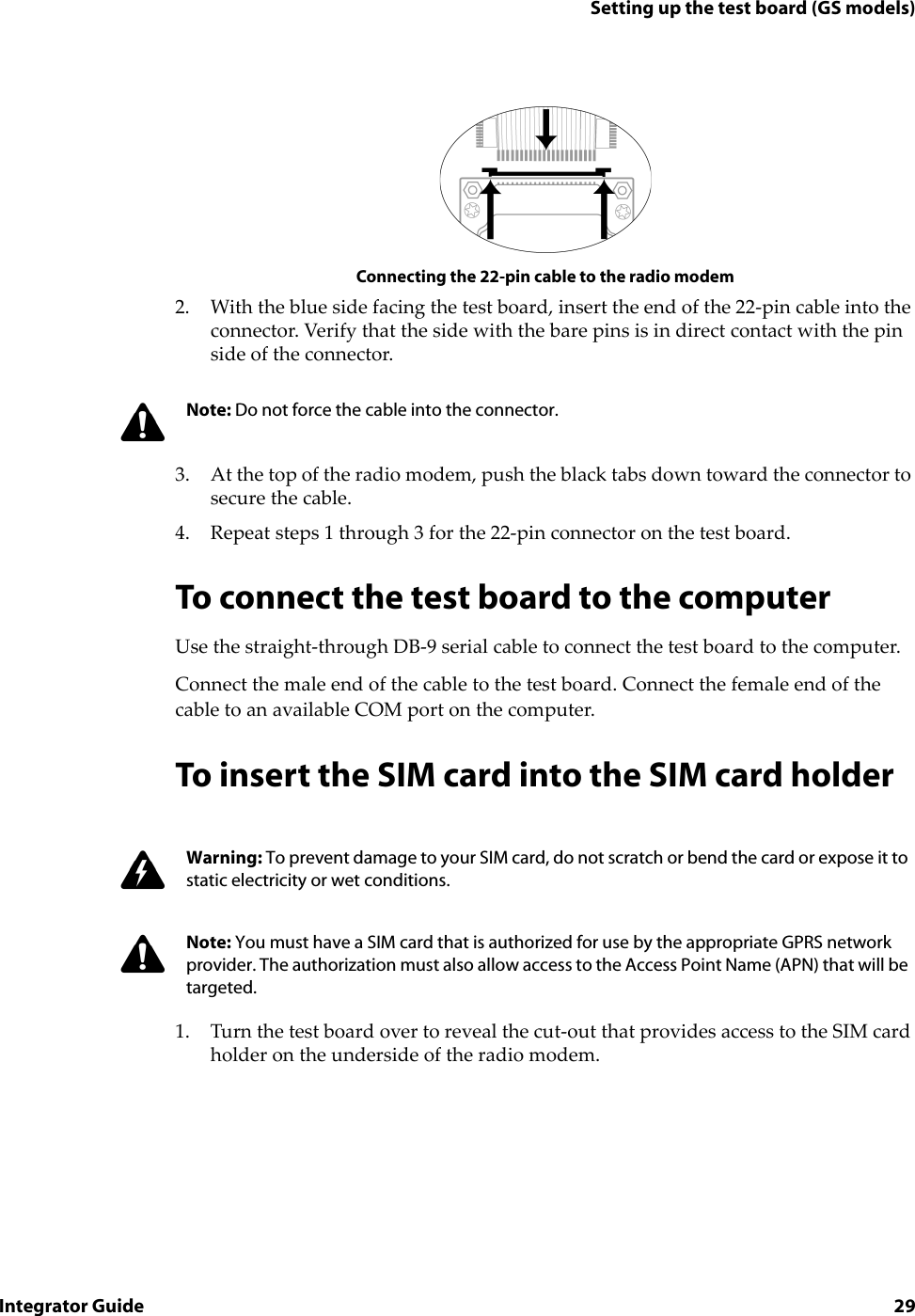

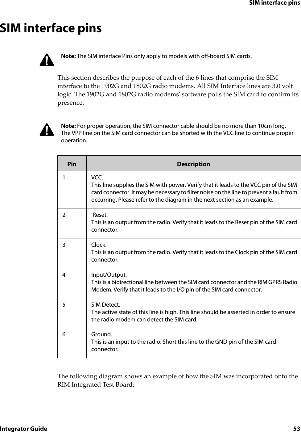
![Chapter 4: Integrating the radio modem42 RIM GPRS Radio ModemSIM interface cable and connectorThe SIM interface cable and connector connects a SIM card to the radio modem. All SIM communication data and power are carried on a flat 6-conductor 0.30 mm (0.012") thick flexible printed circuit (FPC) cable. This cable has 1.00 mm centerline spacing that can plug into a matching connector. Because each application is unique, you may need to create a custom Flat Flex Cable Jumper that has the correct length and connector orientation for your application. Please refer to the diagram below for FPC specifications.FPC interface cable specificationsNote: The interface cable supplied with the Integrator Kit is a Type D 76.2 mm (3.0 inches) long FFC Jumper with 1 mm centerline spacing, Molex part number 210390382.This cable can plug into a matching 22-position 1.0 [0.039] horizontal FPC connector. AMP/Tyco Electronics manufactures a variety of connectors. For information about each connector, including mechanical drawings, visit the manufacturer’s web site (www.amp.com), or contact RIM (oemsupport@rim.net) for help selecting an appropriate connector for your application.Note: The SIM interface cable and connector are only required for the 1902G and 1802G models.](https://usermanual.wiki/BlackBerry/R6420GN.modified-integrators-guide/User-Guide-253530-Page-42.png)
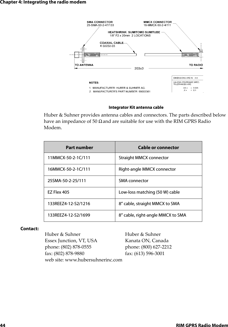
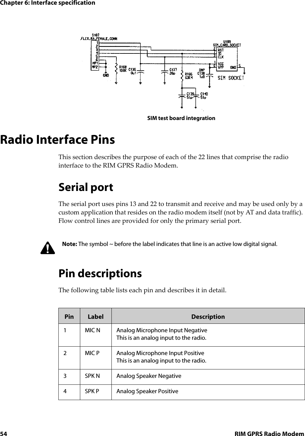
![Cables and connectorsIntegrator Guide 43Antenna cable and connectorsThe antenna cable and connector connects the antenna to the radio modem. RIM uses the industry-standard MMCX connector for the RIM GPRS Radio Modem. The MMCX connector is very small, and it has the mating force to withstand heavy vibration.Typically, an antenna does not plug directly into a RIM GPRS Radio Modem. Instead, a cable is used between the radio’s antenna connector and a second connector at the device’s outer casing. This allows the antenna to be removed from the system without opening the device, and it eliminates a source of strain on the radio’s MMCX connector.The antenna cable that you use should have low loss, an impedance of 50 Ω, and an MMCX plug that mates with the RIM GPRS Radio Modem’s MMCX jack. The other end of the cable can be any connector with an impedance of 50 Ω. An SMA screw-on connector is suitable and widely available. TNC connectors are also suitable, but they are larger than SMA connectors.The following cable is included with the Integrator Kit:Note: The 6-pin interface cable supplied with the Integrator Kit is a 76.2 mm (3.0") long Flat Flex Cable (FFC) Jumper with 1.00 mm centerline spacing and same side conductive surfaces, Parlex part number 100-6-76-B.This cable can plug into a matching 6-position 1.0 [0.039] horizontal FPC connector. A variety of connectors are manufactured by AMP/Tyco Electronics, including AMP part number 487951-6. For information about each connector, including mechanical drawings, visit the manufacturer's web site (www.amp.com), or contact RIM (oemsupport@rim.net) for help with selecting an appropriate connector for your application.Note: The antenna cable supplied with the Integrator Kit has an MMCX connector on one end and an SMA connector on the other. The cable is built with strain reliefs to prevent damage.](https://usermanual.wiki/BlackBerry/R6420GN.modified-integrators-guide/User-Guide-253530-Page-43.png)