BlackBerry R6420GN GPRS OEM Radio Modems 1902GS & 1902G User Manual integrator guide
BlackBerry Limited GPRS OEM Radio Modems 1902GS & 1902G integrator guide
Contents
- 1. user manual
- 2. modified integrators guide
modified integrators guide

RIM GPRS Radio Modem
1902G, 1902GS, 1802G, 1802GS
Integrator Guide
Version 1.0
2
RIM GPRS Radio Modem 1902G, 1902GS, 1802G, 1802GS Integrator Guide
Last revised: 28 June 2002
Part numbers: PDF-04522-002
The information in this document is RIM confidential and is for internal distribution only.
© 2002 Research In Motion Limited. All Rights Reserved. The BlackBerry and RIM families of related
marks, images and symbols are the exclusive properties of Research In Motion Limited. RIM, Research In
Motion, ‘Always On, Always Connected’, the “envelope in motion” symbol and the BlackBerry logo are
registered with the U.S. Patent and Trademark Office and may be pending or registered in other countries.
All other brands, product names, company names, trademarks and service marks are the properties of
their respective owners.
The handheld and/or associated software are protected by copyright, international treaties and various
patents, including one or more of the following U.S. patents: 6,278,442; 6,271,605; 6,219,694; 6,075,470;
6,073,318; D445,428; D433,460; D416,256. Other patents are registered or pending in various countries
around the world. Visit www.rim.net/patents.shtml for a current listing of applicable patents.
While every effort has been made to ensure technical accuracy, information in this document is subject to
change without notice and does not represent a commitment on the part of Research In Motion Limited, or
any of its subsidiaries, affiliates, agents, licensors, or resellers. There are no warranties, express or implied,
with respect to the content of this document.
Research In Motion Limited
295 Phillip Street
Waterloo, ON N2L 3W8
Canada
Research In Motion Europe
Centrum House, 36 Station Road
Egham, Surrey TW20 9LF
United Kingdom
Published in Canada
3
NOTE: This document is provided for informational purposes only, and does not constitute a binding
legal document unless specifically incorporated by reference into a binding legal agreement between you
and Research In Motion (RIM). In the event that you enter into a binding legal agreement with RIM, all
provisions contained in such binding legal agreement shall apply, regardless of whether such provisions
conflict with information contained herein.
RIM assumes no responsibility for any typographical, technical or other inaccuracies in this document.
RIM reserves the right to periodically change information that is contained in this document; however,
RIM makes no commitment to provide any such changes, updates, enhancements or other additions to
this document to you in a timely manner or at all.
FOR INTERNAL USE ONLY. NOT FOR PUBLIC DISTRIBUTION.
The information contained in this document is commercially confidential, for internal use only, and must
not be disclosed to any third party without the express written consent of RIM. This document is to be
treated as Confidential Information for the purposes of any Non-Disclosure Agreement between you and
RIM.
Warning: This document is for the use of licensed users only. Any unauthorized copying, distribution or
disclosure of information is a violation of copyright laws. No reproduction in whole or in part of this
document may be made without express written consent of RIM.
THERE ARE NO WARRANTIES, EXPRESS OR IMPLIED, WITH RESPECT TO THE CONTENT OF THIS
DOCUMENT, AND ALL INFORMATION PROVIDED HEREIN IS PROVIDED "AS IS". IN NO EVENT
SHALL RIM BE LIABLE TO ANY PARTY FOR ANY DIRECT, INDIRECT, SPECIAL OR
CONSEQUENTIAL DAMAGES FOR ANY USE OF THIS DOCUMENT, INCLUDING WITHOUT
LIMITATION, RELIANCE ON THE INFORMATION PRESENTED, LOST PROFITS OR BUSINESS
INTERRUPTION, EVEN IF RIM WAS EXPRESSLY ADVISED OF THE POSSIBILITY OF SUCH
DAMAGES.
4


Important Safety and compliance information
6RIM GPRS Radio Modem
FCC compliance statement (USA)
FCC Class B Part 15
This device complies with Part 15 of the FCC Rules. Operation is subject to the
following two conditions:
•This device may not cause harmful interference, and
•This device must accept any interference received, including interference that
may cause undesired operation.
This equipment has been tested and found to comply with the limits for a Class B
digital device, pursuant to Part 15 of the FCC Rules. These limits are designed to
provide reasonable protection against harmful interference in a residential
installation. This equipment generates, uses and can radiate radio frequency energy
and, if not installed and used in accordance with the manufacturer’s instructions, may
cause interference harmful to radio communications.
There is no guarantee, however, that interference will not occur in a particular
installation. If this equipment does cause harmful interference to radio or television
reception, which can be determined by turning the equipment off and on, the user is
encouraged to try to correct the interference by one or more of the following
measures:
•Reorient or relocate the receiving antenna.
•Increase the separation between the equipment and receiver.
•Connect the equipment into an outlet on a circuit different from that to which the
receiver is connected.
•Consult the dealer or an experienced radio/TV technician for help.
Industry Canada Certification
This device complies with Industry Canada RSS 133, under certification number
2503A-R6020GN.
Class B compliance
This device complies with the Class B limits for radio noise emissions as set out in the
interference-causing equipment standard entitled “Digital Apparatus,” ICES-003 of
Industry Canada.
Warning: Changes or modifications to this unit not expressly approved by the party
responsible for compliance could void the user’s authority to operate this equipment.
Contents
Important Safety and compliance information................................................................ 5
FCC compliance statement (USA)...........................................................................6
Industry Canada Certification .................................................................................6
Class B compliance.............................................................................................6
About this guide................................................................................................................11
Related documentation...........................................................................................11
CHAPTER 1 Introduction to the RIM GPRS Radio Modem.................................................................. 13
About the RIM GPRS Radio Modem ....................................................................14
Range of applications.......................................................................................15
Receiver sensitivity...........................................................................................15
Noise immunity ................................................................................................15
Powerful and efficient transmitter.................................................................16
Small size ...........................................................................................................16
GPRS network technology......................................................................................16
CHAPTER 2 Getting Started.................................................................................................................. 19
About the Integrator Kit .........................................................................................20
Working with RIM...................................................................................................20
Integration overview...............................................................................................21
CHAPTER 3 Setting up the test board ................................................................................................. 25
Test board components...........................................................................................26
Setting up the test board (GS models) ..................................................................27
To connect the radio modem to the test board.............................................28
To connect the test board to the computer ...................................................29
To insert the SIM card into the SIM card holder..........................................29
To connect the antenna to the radio modem................................................30
To connect the test board to an AC outlet.....................................................31
To turn on the system ......................................................................................31
To connect the headset.....................................................................................31
Setting up the test board (G models) ....................................................................32
To connect the SIM card to the test board.....................................................33
To connect the radio modem to the test board.............................................34
To connect the test board to the computer ...................................................35
To insert the SIM card into the SIM card holder..........................................35
To connect the antenna to the radio modem................................................36
To connect the test board to an AC outlet.....................................................36
To turn on the system ......................................................................................36
To connect the headset.....................................................................................36
CHAPTER 4 Integrating the radio modem .......................................................................................... 37
Overview...................................................................................................................38
Environmental properties.......................................................................................38
Storage temperature ................................................................................................38
Operating temperature ...........................................................................................38
Physical properties ..................................................................................................38
Weight ................................................................................................................38
Dimensions........................................................................................................39
Mounting methods ..................................................................................................39
Bolts or standoffs ..............................................................................................40
Tie wraps............................................................................................................40
Permanent industrial adhesive.......................................................................41
Cables and connectors.............................................................................................41
Radio interface cable and connector..............................................................41
SIM interface cable and connector .................................................................42
Antenna cable and connectors........................................................................43
CHAPTER 5 Power Requirements ........................................................................................................ 45
Load specifications ..................................................................................................46
Power supply parameters ...............................................................................46
Ripple specification ..........................................................................................46
Power requirements ................................................................................................47
Batteries.....................................................................................................................47
Rechargeable batteries .....................................................................................47
Single-use batteries...........................................................................................48
Plug-in supplies .......................................................................................................48
Automotive supplies...............................................................................................48
CHAPTER 6 Interface specification ...................................................................................................... 51
RIM GPRS Radio Modem interface.......................................................................52
AT Commands .........................................................................................................52
SIM interface pins ....................................................................................................53
Radio Interface Pins.................................................................................................54
Serial port...........................................................................................................54
Pin descriptions ................................................................................................54
Turning off and turning on the radio ...................................................................58
Turning on the radio ........................................................................................58
Turning off the radio........................................................................................58
Resetting the Radio...........................................................................................59
Loading firmware (optional)..................................................................................59
CHAPTER 7 Antenna selection .............................................................................................................61
Introduction to antenna terminology ...................................................................62
Gain and ERP ....................................................................................................62
Impedance matching, return loss, and VSWR .............................................62
Antenna size......................................................................................................63
Selecting an antenna................................................................................................63
Antenna requirements ............................................................................................64
Antenna design considerations .............................................................................64
Vertical polarization.........................................................................................65
Proximity to active electronics........................................................................65
Transmit interference.......................................................................................65
Device position .................................................................................................65
Antenna cable....................................................................................................66
Additional notes ...............................................................................................66
Shielding ...................................................................................................................67
CHAPTER 8 Certification....................................................................................................................... 69
FCC radio frequency exposure rules ....................................................................70
Complying with FCC SAR/MPE guidelines........................................................70
Antenna..............................................................................................................70
SAR and MPE limits.........................................................................................71
Guidelines..........................................................................................................71
Operating manual compliance statement .....................................................71
Labelling ............................................................................................................72
For more information.......................................................................................72
CHAPTER 9 Specifications .................................................................................................................... 73
Power supply & typical current usage .................................................................74
RF properties ............................................................................................................74
Serial communications............................................................................................74
Other features...........................................................................................................74
Mechanical & environmental properties..............................................................75
Audio.........................................................................................................................75
Gain setting........................................................................................................76
Frequency response (voiceband filter) ..........................................................76
Input/output impedance .................................................................................76
Signal to (noise + distortion) ...........................................................................76
CHAPTER 10 Glossary ............................................................................................................................. 77
Index .................................................................................................................................. 81

About this guide
This guide explains how to integrate the RIM GPRS Radio Modem
into a variety of devices such as laptop computers, handhelds,
vending machines, point-of-sale terminals, vehicle-based mobile
terminals, and alarm systems.
This guide includes the following topics:
•integration overview
•test board overview
•mounting requirements
•power (battery) requirements
•interfacing to the RIM radio modem
•antenna selection and placement
Throughout the guide, there are suggestions and precautions that can
ease the implementation of a wireless communication solution. To
discuss the technical integration of this radio modem, contact RIM at
oemsupport@rim.net.
Related documentation
The Integrator Kit also includes the RIM GPRS Radio Modem AT
Command Reference, which lists the AT commands that apply to the
RIM GPRS Radio Modem.
About this guide
12 RIM GPRS Radio Modem


Chapter 1: Introduction to the RIM GPRS Radio Modem
14 RIM GPRS Radio Modem
About the RIM GPRS Radio Modem
With the introduction of the RIM GPRS Radio Modem, Research In Motion® (RIM®)
sets a new standard for radio modem performance. Its small size and weight makes it
suitable for virtually any wireless data and voice application, including handheld
devices and mobile terminals. Its multislot class allows for the highest possible
download rates allowed using a single receiver on a GPRS network.
The RIM GPRS Radio Modem consists of the following models:
•1902G
•1902GS
•1802G
•1802GS
The RIM GPRS Radio Modem offers the following advantages:
•range of applications
•radio performance
•reciever sensitivity
•noise immunity
•powerful and efficient transmitter
•small size
Model Description
1902G This model is designed for use with GPRS and GSM wide-area wireless
data/voice networks operating in the 1900 and 850 MHz range in North
America. It is identical to the 1902GS, but it has a 6-pin zif connection, which
allows you to position the SIM card in the location that best suits your
design.
1902GS This model is designed for use with GPRS and GSM wide-area wireless
data/voice networks operating in the 1900 and 850 MHz range in North
America. It is identical to the 1902G, but it has an on-board SIM card.
1802G This model is designed for use with GPRS and GSM wide-area wireless voice
and data networks operating in the 900 MHz and 1800 MHz ranges. It is
identical to the 1802GS, but it has a 6-pin zif connection, which allows you
to position the SIM card in the location that best suits your design.
1802GS This model is designed for use with GPRS and GSM wide-area wireless voice
and data networks operating in the 900 MHz and 1800 MHz ranges. It is
identical to the 1802G, but has an on-board SIM card.

About the RIM GPRS Radio Modem
Integrator Guide 15
These advantages are described below.
Range of applications
RIM radio modems are designed to integrate easily into a computing device and are
suitable for a wide range of applications, including:
•laptop computers
•vehicle tracking
•point-of-sale devices
•monitoring and telemetry
•ruggedized terminals
•vending machines
•handheld computers
•utility meters
•parking meters
•billboards
•dispatching
•security alarm panels
Receiver sensitivity
Receiver sensitivity is a measure of how well the radio modem can receive and
decode data from a network base station. This figure is important when a device is
used in areas where signal strength is weak, such as inside buildings and in locations
that are not close to a base station. A radio modem with good receiver sensitivity can
be used in more places than a radio modem with poor receiver sensitivity.
The RIM GPRS Radio Modem typically has a receiver sensitivity of -107 dBm with a
2.4% bit error rate (BER).
Noise immunity
The RIM GPRS Radio Modem is not desensitized by the electromagnetic interference
(EMI) or “noise” generated by the electronics of the terminal into which it is
integrated. As a result, no special shielding is required between the radio and your
device.
Note: BER is an industry standard error rate used to define sensitivity; it does not indicate that
2.4% of the data that is passed by the radio to the application is corrupted.
Chapter 1: Introduction to the RIM GPRS Radio Modem
16 RIM GPRS Radio Modem
Noise immunity offers several key benefits:
•easier integration
•longer battery life
•increased reliability
•improved RF performance
•more coverage from each base station
•no need for special RF shielding
Powerful and efficient transmitter
When necessary, the RIM GPRS Radio Modem can supply a full 1.0 watt at 1900 MHz.
However, the RIM GPRS Radio Modem quickly decreases the output power when it is
close to a base station, because a stronger signal is needed only when the radio
modem is far from a base station. By transmitting a strong signal only when it is
necessary, the RIM GPRS Radio Modem conserves battery power and ensures a
balanced link.
Preliminary results indicate that the RIM GPRS Radio Modem provides reliable
transmit efficiency across the entire operating voltage range of 3.5 to 4.75 volts. As a
result, batteries can be used even when nearing depletion. The transmit efficiency also
maximizes the radio coverage area throughout the life of the battery. Final numbers
are yet to be determined.
Small size
Because of its single board design, the RIM GPRS Radio Modem is very thin and, at
only 42.0 by 67.5 mm, is smaller than a business card. This tiny size allows the RIM
GPRS Radio Modem to meet most applications’ tight space requirements. The radio
modem’s single-board design is more reliable than multi-board designs, particularly
in high-vibration environments (such as vehicles) or in devices that can be dropped
(such as handheld devices).
GPRS network technology
The Global System for Mobile Communication (GSM), first deployed by Oy
Radiolinja Ab of Finland in 1992, has become the international voice communication
standard. The General Packet Radio Service (GPRS) supplement to the GSM network
was first proposed in 1992 to combine telecom and datacom, and the result has been
well-received. For more information on GSM and GPRS, visit http://www.gsm.org.

GPRS network technology
Integrator Guide 17
GPRS is a packet switched overlay to the circuit switched GSM network that gives a
mobile device on that network “always on” capabilities. GPRS allows for a theoretical
maximum transfer speed of 171.2 kbps. It is also IP-based, which means that a mobile
device on the GPRS network is Internet-aware.
GPRS networks are deployed worldwide. There are currently 172 countries with
deployed GSM networks. Enabling GPRS communication on GSM networks requires
only two additional hardware devices and a software upgrade. Many GSM network
providers have already supplemented their networks with GPRS capability. GPRS
technology is deployed or is being deployed in the following countries:
Australia Germany Luxembourg Singapore
Austria Greece Malaysia Slovenia
Belgium Hong Kong Malta South Africa
Canada Hungary Netherlands Spain
China Iceland New Zealand Sweden
Croatia Ireland Norway Switzerland
Czech
Republic
Israel Philippines Taiwan
Denmark Italy Poland Turkey
Estonia Lebanon Portugal United Arab
Emirates
Finland Liechtenstein Romania United
Kingdom
French W.
Indies
Lithuania Russia United States
Note: The RIM 1902G and 1902GS models are compatible with networks in North America that
operate in the 1900 and 850 MHz range.
The RIM 1802G and 1802GS models are compatible with networks, usually in Europe, that
operate in the 900 and 1800 MHz range.
Chapter 1: Introduction to the RIM GPRS Radio Modem
18 RIM GPRS Radio Modem


Chapter 2: Getting Started
20 RIM GPRS Radio Modem
About the Integrator Kit
RIM is committed to facilitating RIM GPRS Radio Modem integration. RIM provides
resources for you to evaluate the feasibility of implementing a wireless
communication solution and works closely with partners to develop an application in
the shortest time possible.
The Integrator Kit includes several tools to help streamline the evaluation and
integration process. Using the kit, you can quickly interface the radio modem to your
computing device.
Working with RIM
RIM has an experienced team to help you with design and implementation. If you
need help getting started, or if you have any questions about the radio technology or
its integration into your platform, contact the engineering development team:
phone: +1 (519) 888-7465 ext. 5200
fax: +1 (519) 883-4940
email: oemsupport@rim.net
web site: http://www.rim.net/oem
Note: The radio modem that is part of the Integrator Kit is not activated on the GPRS network
until a SIM card, which has been activated for GPRS communication, is attached to the device
through the proper lines. Contact your GPRS network provider to obtain a SIM card and activate
the radio modem.
Integration overview
Integrator Guide 21
Integration overview
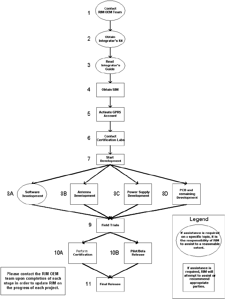
The following flowchart illustrates the integration process.

Chapter 2: Getting Started
22 RIM GPRS Radio Modem
Step Description
Contact the RIM OEM team Email OEMinquiry@rim.net or call (519) 888-7465 x5200 to
obtain more information about RIM Radio Modem products
and whether they are suitable for your application.
Obtain Integrator Kit Request the Integrator Kit from Research In Motion. This kit
includes the radio modem, two mechanical samples of the
radio, an interface and test board, AC to DC power supply,
required cables, magnetic mount antenna, and
documentation.
Read the Integrator Guide Read the Integrator Guide first to make sure that you follow
proper procedures to prevent unnecessary delays and
equipment damage. This guide explains topics such as
mounting requirements, battery power characteristics,
interfaces to the RIM radio modem, and antenna selection
and placement.
Obtain SIM Contact the appropriate network provider to obtain a SIM
card.
For network contact information, visit
http://www.rim.net/oem or contact RIM at
oemsupport@rim.net.
Activate GPRS account Contact the appropriate network provider to activate the
GPRS account.
For network contact information, visit
http://www.rim.net/oem or contact RIM at
oemsupport@rim.net.
Contact Certification Labs Learn about obtaining FCC and/or Industry Canada
certification. Radio frequency (RF) emitting products cannot
be sold in the United States or Canada until you have the
necessary government approvals. Understanding what you
are permitted to do before beginning your design will help
you to avoid redesign costs.
For more information on testing, visit
http://www.rim.net/oem/ or contact the RIM at
oemsupport@rim.net.
Start Development Plan your project carefully before starting development. You
must address several important considerations when
planning your design. To speed up the development process,
you can often perform several procedures in-parallel.
Contact RIM at oemsupport@rim.net for further details.

Integration overview
Integrator Guide 23
Develop Software Contact RIM if you encounter any problems with the
communication between the offboard processor and the
radio.
Develop an Antenna Start developing an antenna. The antenna that is provided
with the Integrator Kit has been certified for use with the RIM
GPRS Radio Modem. If this antenna does not meet your
needs, develop an antenna for use with the final product.
Refer to the Integrator Guide for guidelines selecting an
antenna.You can also contact RIM for general assistance and
for recommendations of antenna companies that can
provide further assistance.
Develop a Power Supply Start developing the power supply for the product. Refer to
the Integrator Guide for guidelines on the strict power
requirements of the RIM radio modem.
Contact RIM at oemsupport@rim.net for further details on
power requirements, guidelines for power supply
development, and recommendations of power supply
companies that can provide further assistance.
Complete PCB and
Remaining Development
Start developing the housing and Printed Circuit Board (PCB)
for the product.
Refer to the Integrator Guide for guidelines on radio and
antenna placement.
Conduct Field Trials Start product field trials to ensure performance and reliability.
Perform Certification Choose a testing lab to perform FCC or Industry Canada
certification and any applicable network certification. Before
sending your product for testing, contact RIM to make sure
that the solution is set up properly for testing. For more
information, visit http://www.rim.net/oem/.
Pilot/Beta Release Contact RIM prior to beta release of the product, especially if
the product has not been certified yet. There are specific
guidelines that must be followed prior to certification to
make sure that the release conforms to legal requirements.
Final Release Congratulations on completing the development process!
Contact RIM if you encounter any obstacles related to the RIM
GPRS Radio Modem. Please also provide RIM with regular
updates on the release’s progress.
Step Description
Chapter 2: Getting Started
24 RIM GPRS Radio Modem


Chapter 3: Setting up the test board
26 RIM GPRS Radio Modem
Test board components
The RIM test board provides a standard RS-232 serial interface between a computer
and the radio modem. The test board allows you to connect the RIM GPRS Radio
Modem to a standard computer using a COM port or to a terminal device using a
RS-232 serial port. The test board also provides access points to the radio’s
communication port, which enables you to monitor activity with a logic probe,
multimeter, or oscilloscope.
The test board includes the following components and functionality:
•RS-232 interface
•on/off switch
•test points
•power supply
•LED indicators
•standard SIM slot
•microphone/speaker jack
The test board components and functionality are described below.
Component Description
RS-232 interface The serial (COM) port on a computer and most terminal
devices operates at RS-232 signal levels, which are typically
±12V. This high voltage would damage the RIM GPRS Radio
Modem, which is typically integrated into a device that
operates an asynchronous serial port at 3.0V. The RS-232
interface on the test board allows you to produce an output
from the radio that is easily interpreted by a computer.
On/off switch When the switch is on, the radio turns on whenever power is
applied to the test board. When the switch is off, the radio
shuts down. Refer to "Turning off and turning on the radio" on
page 58 for more information.
Test points The test board is more than an RS-232 interface. It provides
direct access to each of the 22 pins on the radio interface
cable, which enables connectivity to analytical
equipment—such as a logic probe, multimeter, or
oscilloscope—and real-time data flow indication.
Setting up the test board (GS models)
Integrator Guide 27
Setting up the test board (GS models)
To use the test board that is provided with your Integrator Kit, you must connect the
RIM GPRS Radio Modem to an antenna, SIM card, and a computer (or another device
with a RS-232 serial interface). Use the test board and cables that are supplied with
your Integrator Kit.
To set up the test board, complete these tasks in the following order:
1. Connect the radio modem to the test board.
2. Connect the test board to the computer.
3. Insert the SIM card into the SIM card holder.
4. Connect the antenna to the radio modem.
5. Connect the test board to an AC outlet.
6. Turn on the system.
7. Connect the headset.
The following graphic illustrates the GS model test board and major components.
Power supply The RIM GPRS Radio Modem requires a clean, high-current
power source. RIM uses a standard plug-pack to provide the
current that is necessary to operate the radio. The voltage is
converted into the necessary levels by the power supply
section on the test board.
LED indicators The test board includes light emitting diode (LED) indicators
that are designed to indicate the flow of data to and from the
host (in real time), the radio power status, power to the test
board, network coverage, and more.
Standard SIM card holder The test board includes a SIM card holder for use with
standard 3V or 5V SIM cards. The SIM card is necessary in order
to access GSM/GPRS networks.
Microphone/speaker jack The test board includes a microphone/speaker jack for use
with the headset that is included in the Integrator Kit. The
microphone/speaker jack enables the integrator to take
advantage of the GSM circuit-switched voice network that
underlies the GPRS networks.
Component Description
Note: These steps apply to on-board SIM models (GS) only.
Chapter 3: Setting up the test board
28 RIM GPRS Radio Modem
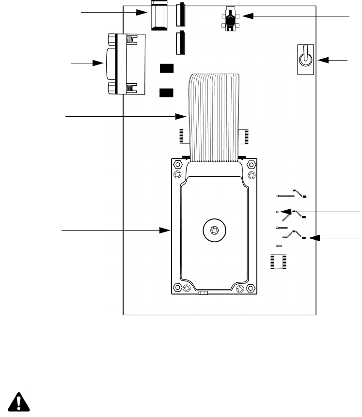
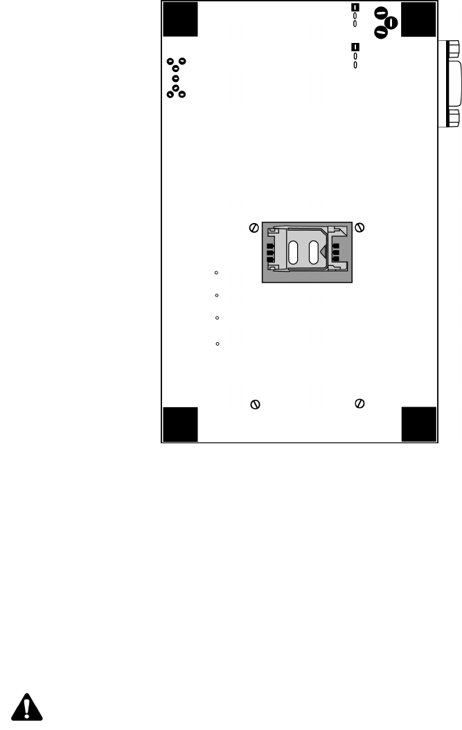
GS model test board — top view
To connect the radio modem to the test board
The 22-pin flat interface cable supplies clean, regulated power to the radio and carries
most of the data and all of the voice between the test board and the radio modem. This
cable also carries control and status signals, such as ONI.
1. At the top of the radio modem, push the two black tabs up and away from the
connector.
microphone/
on/off switch
test point
LED
power jack
RS-232
22-pin
GPRS
speaker jack
interface
indicator
connector
Radio Modem
cable
Note: This step is only necessary if the radio modem is not already connected to the test board.
Setting up the test board (GS models)
Integrator Guide 29
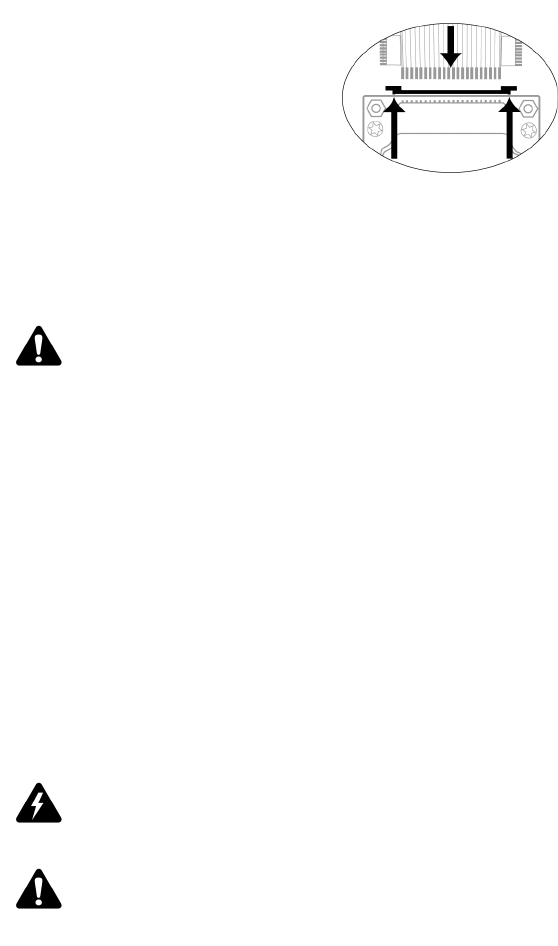
Connecting the 22-pin cable to the radio modem
2. With the blue side facing the test board, insert the end of the 22-pin cable into the
connector. Verify that the side with the bare pins is in direct contact with the pin
side of the connector.
3. At the top of the radio modem, push the black tabs down toward the connector to
secure the cable.
4. Repeat steps 1 through 3 for the 22-pin connector on the test board.
To connect the test board to the computer
Use the straight-through DB-9 serial cable to connect the test board to the computer.
Connect the male end of the cable to the test board. Connect the female end of the
cable to an available COM port on the computer.
To insert the SIM card into the SIM card holder
1. Turn the test board over to reveal the cut-out that provides access to the SIM card
holder on the underside of the radio modem.
Note: Do not force the cable into the connector.
Warning: To prevent damage to your SIM card, do not scratch or bend the card or expose it to
static electricity or wet conditions.
Note: You must have a SIM card that is authorized for use by the appropriate GPRS network
provider. The authorization must also allow access to the Access Point Name (APN) that will be
targeted.
Chapter 3: Setting up the test board
30 RIM GPRS Radio Modem
Underside of the test board showing the on-board SIM card holder
2. Slide the SIM card holder in the direction of the arrow to unlock it, and then lift
the cover open.
3. Slide the SIM card into the cover with the conductive side facing the leads on the
board. The notched end of the SIM card should align with the notch in the SIM
card holder.
4. Close the cover, and then slide the cover in the reverse direction of the arrow to
lock it into place.
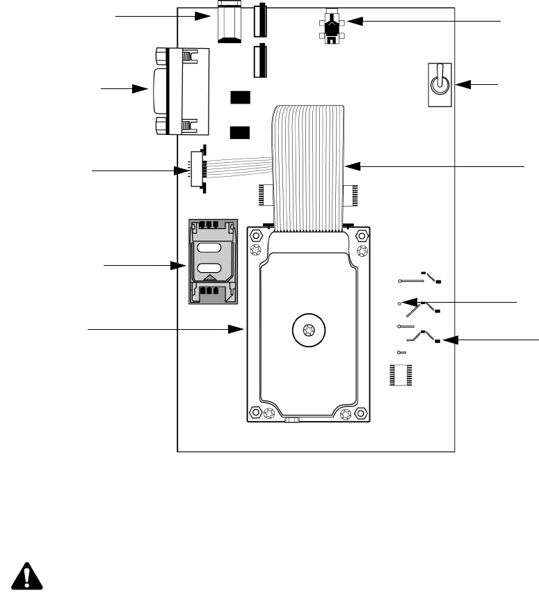
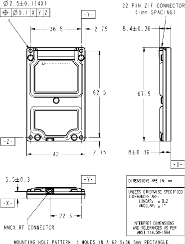
To connect the antenna to the radio modem
The Integrator Kit includes a high-performance, 3 dB-gain magmount antenna, which
is terminated by a screw-on SMA plug. The radio modem includes a snap-on MMCX
jack.
Note: If you connect the antenna before you connect the test board to an AC outlet, the unit
detects network coverage more reliably.
Setting up the test board (GS models)
Integrator Guide 31
1. Insert the antenna into the base and turn the antenna until the two components
are securely fastened.
2. Insert the SMA cable connector into the MMCX connector and turn the SMA
connector until the two components are securely fastened.
SMA cable connector and MMCX connector
3. Insert the MMCX connector into the radio modem’s MMCX jack.
4. Position the antenna for optimal coverage. The magmount antenna provides
optimum RF performance when it is placed on a broad metal surface, such as the
roof of a car. If you are using the antenna inside a building, for improved
performance, place it near a window, with few obstacles (such as a wall, furniture,
or equipment) between the antenna and the window.
To connect the test board to an AC outlet
Plug the 5VDC, 2.4A, center-pin-positive power adapter into a wall outlet. Connect
the other end to the test board’s power jack.
To turn on the system
Switch the power switch to the TURNON position to allow the radio modem to power
up.
When the radio is on, the LED marked ONI is lit. Refer to "Turning off and turning on
the radio" on page 58 for more information.
To connect the headset
Insert the headset plug into the audio jack.

Chapter 3: Setting up the test board
32 RIM GPRS Radio Modem
Setting up the test board (G models)
To use the test board that is provided with your Integrator Kit, you must connect the
RIM GPRS Radio Modem to an antenna, SIM card, and computer (or another device
with a RS-232 serial interface). Use the test board and cables that are supplied with
your Integrator Kit.
To set up the test board, complete these tasks in the following order:
1. Connect the SIM card to the test board.
2. Connect the radio modem to the test board.
3. Connect the test board to the computer.
4. Insert the SIM card into the SIM card holder.
5. Connect the antenna to the radio modem.
6. Connect the test board to an AC outlet.
7. Turn on the system.
8. Connect the headset.
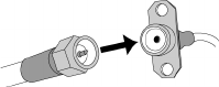
The following graphic illustrates the G model test board and major components.
Note: These steps apply to off-board SIM models (G) only.
Setting up the test board (G models)
Integrator Guide 33
G model test board — top view
To connect the SIM card to the test board
The 6-pin flat SIM interface cable carries the data and power between the test board
SIM slot and the radio modem.
1. Remove the radio modem from the test board: unfasten the nuts and lift the radio
modem up and away from the test board.
2. On the underside of the modem, on the connector, push the two black tabs up
from the connector to widen the opening.
microphone/
on/off switch
test point
LED
power jack
RS-232
22-pin
GPRS
speaker jack
interface
indicator
connector
Radio Modem
cable
6-pin
SIM card
connector
holder
Note: This task only applies to the 1802G and 1902G models.

Chapter 3: Setting up the test board
34 RIM GPRS Radio Modem
Underside of radio modem showing the 6-pin connector
3. With the blue side facing the test board, insert the end of the cable 6-pin cable into
the connector. Verify that the side with the bare pins is in direct contact with the
pin side of the connector.
4. Push the black tabs down toward the connector to secure the cable.
5. Repeat steps 2 through 4 to connect the 6-pin connector to the test board.
6. Re-attach the radio modem to the test board.
To connect the radio modem to the test board
The 22-pin flat interface cable supplies clean, regulated power to the radio and carries
most of the data and all of the voice between the test board and the radio modem. This
cable also carries control and status signals, such as ONI.
1. At the top of the radio modem, push the two black tabs up and away from the
connector.
Note: Do not force the cable into the connector.
Note: This step is only necessary if the radio modem is not already connected to the test board.

Setting up the test board (G models)
Integrator Guide 35
Connecting the 22-pin cable to the radio modem
2. With the blue side facing the test board, insert the end of the 22-pin cable into the
connector. Verify that the side with the bare pins is in direct contact with the pin
side of the connector.
3. At the top of the radio modem, push the black tabs down toward the connector to
secure the cable.
4. Repeat steps 1 through 3 for the 22-pin connector on the test board.
To connect the test board to the computer
Use the straight-through DB-9 serial cable to connect the test board to the computer.
Connect the male end of the cable to the test board. Connect the female end of the
cable to the computer’s COM port.
To insert the SIM card into the SIM card holder
1. Slide the SIM card holder in the direction of the arrow to unlock it, and then lift
the cover open.
2. Slide the SIM card into the cover with the conductive side facing the leads on the
board. The notched end of the SIM card should align with the notch in the SIM
card holder.
3. Close the cover, and then slide the cover in the reverse direction of the arrow to
lock it into place.
Note: Do not force the cable into the connector.
Warning: To prevent damage to your SIM card, do not scratch or bend the card or expose it to
static electricity or wet conditions.
Note: You must have a SIM card that is authorized for use by the appropriate GPRS network
provider. The authorization must also allow access to the Access Point Name (APN) that will be
targeted.
Chapter 3: Setting up the test board
36 RIM GPRS Radio Modem
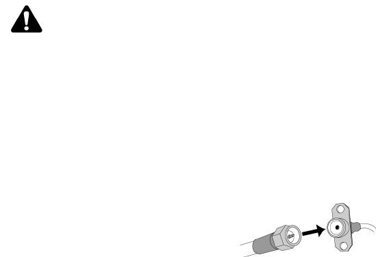
To connect the antenna to the radio modem
The Integrator Kit includes a high-performance, 3 dB-gain magmount antenna, which
is terminated by a screw-on SMA plug. The radio modem includes a snap-on MMCX
jack.
1. Insert the antenna into the base and turn the antenna until the two components
are securely fastened.
2. Insert the SMA cable connector into the MMCX connector and turn the SMA
connector until the two components are securely fastened.
SMA cable connector and MMCX connector
3. Insert the MMCX connector into the radio modem’s MMCX jack.
4. Position the antenna for optimal coverage. The magmount antenna provides
optimum RF performance when it is placed on a broad metal surface, such as the
roof of a car. If you are using the antenna inside a building, for improved
performance, place it near a window, with few obstacles (such as a wall, furniture,
or equipment) between the antenna and the window.
To connect the test board to an AC outlet
Plug the 5VDC, 2.4A, center-pin-positive power adapter into a wall outlet. Connect
the other end to the test board’s power jack.
To turn on the system
Switch the power switch to the TURNON position to allow the radio modem to power
up.
When the radio is on, the LED marked ONI is lit. Refer to "Turning off and turning on
the radio" on page 58 for more information.
To connect the headset
Insert the headset plug into the audio jack.
Note: If you connect the antenna before you connect the test board to an AC outlet, the unit
detects network coverage more reliably.


Chapter 4: Integrating the radio modem
38 RIM GPRS Radio Modem
Overview
This section provides you with information on issues that you should consider when
you are developing your application’s hardware. You can use this information and
the additional components provided with the Integrator Kit as a resource as you
develop your application’s hardware.
The Integrator Kit includes several components that can help you develop your
product’s housing and physically integrate the radio modem and associated
hardware into your your application. These components consist of two 22-pin
connector cables, two 6-pin connector cables (G models only), and two radio modem
mechanical samples.
Environmental properties
Environmental testing ensures that RIM products can withstand both typical and
extreme real-world conditions.
During environmental testing, RIM takes samples of its radio modems and subjects
them to a variety of harsh conditions. Each unit in the sample is also visually
inspected after testing. This experience enables RIM to fine-tune its design and
manufacturing process.
Storage temperature
The RIM GPRS Radio Modem can be stored at a temperature from -40°C to 85°C
(-40°F to 185°F).
Operating temperature
The RIM GPRS Radio Modem operates between -30°C to 75°C (-22°F to 158°F).
Physical properties
Weight
The RIM GPRS Radio Modem weighs 36 g (1.2 oz), including the case.
Warning: You should warn end users not to exceed the upper temperature limit; doing so can
result in performance degradation or damage to the power amplifier, especially during
transmission.
Mounting methods
Integrator Guide 39
Dimensions
RIM radio modems meet stringent space requirements. The maximum dimensions of
the radio modem, not including cables, are:
Width 42.0 mm (1.65 inches)
Length 67.5 mm (2.66 inches)
Thickness 8.4 mm (0.33 inches)
Mounting methods
RIM GPRS Radio Modems can be securely fastened using a variety of methods;
however, you must consider the operating environment when you choose a mounting
option. For example, extreme temperature, heavy vibration, or areas with high
electromagnetic interference can require a special mounting solution. You must make
sure that the radio modem remains securely attached in the environment where it is
used.
This section describes the following mounting methods:
•bolts or standoffs
•tie wraps
•permanent industrial adhesive
Chapter 4: Integrating the radio modem
40 RIM GPRS Radio Modem
The following information is presented as a guide; however, applications can vary
considerably. A mechanical engineer can help you make sure that the mounting
method that you choose is suitable for your application.
Bolts or standoffs
The radio modem includes a hole in each corner, which can be used to bolt the device
onto a circuit board, device housing, standoffs, or other surface. The mounting hole
pattern is four holes in a 62.5-by-36.5 mm rectangle, with each hole 2.5 mm in
diameter.
To allow room under the radio for components on your board, you can use standoffs
instead of bolts, as illustrated in the following diagram.
Tie wraps
You can also use tie wraps as a secure but non-permanent means of attaching the
radio modem to a surface. Typically, each tie wrap passes through a hole drilled into
the board’s surface on either side of the radio modem. This enables the radio to be
attached to a shell, a PCB, or other mounting surfaces.

Cables and connectors
Integrator Guide 41
Permanent industrial adhesive
The RIM GPRS Radio Modem is small and lightweight enough to be attached to the
host device using an industrial adhesive. For some applications, this mounting
method is preferable to bolts, because adhesive is easier to use in a manufacturing
environment and is more resistant to loosening than bolts. In many cases, an effective
solution is to adhere the radio modem to the inside surface of your product’s casing.
Choose an adhesive based on its ability to stick to the material used in the radio
modem’s outer casing and the surface to which the radio modem will be mounted.
The RIM GPRS Radio Modem’s bottom casing is magnesium.
Cables and connectors
The radio modem includes the following connectors:
•radio interface connector
•SIM interface connector (G models only)
•antenna connector
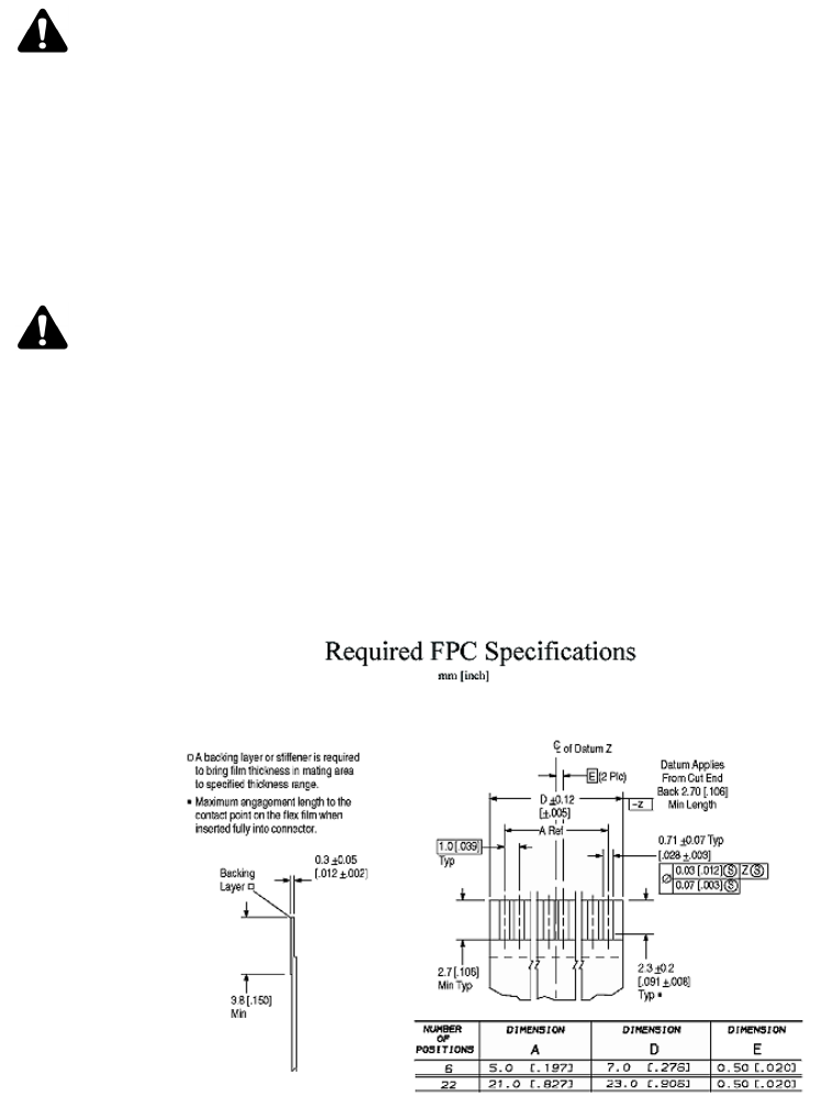
Radio interface cable and connector
The radio interface connector connects the radio modem to a serial computing device,
speaker and microphone, and power supply. Serial communication data, control
signals, and power are carried on a flat 22-conductor 0.30 mm (0.012 inches) thick
flexible printed circuit (FPC) cable. This cable has 1-mm centerline spacing that can
plug into a matching connector.
Because each application is unique, you may need to create a custom Flat Flex Cable
(FFC) Jumper that has the correct length and correct connector orientation for your
application. Please refer to the diagram in the next section for FPC specifications.
Warning: If you use tie wraps, make sure that the surface beneath the radio modem is flat.
Otherwise, the mounting surface can push up on the bottom surface of the radio case, and the
tie wraps, when tightened, can push down on the edge of the radio case. This pressure can
cause the radio modem’s metal case to flex upward and short components inside the radio. To
avoid this malfunction, you should not use thick adhesive foam tape and tie wraps together.
Note: You should choose foam tape for rough surfaces and adhesive tape for smooth surfaces.
Chapter 4: Integrating the radio modem
42 RIM GPRS Radio Modem
SIM interface cable and connector
The SIM interface cable and connector connects a SIM card to the radio modem. All
SIM communication data and power are carried on a flat 6-conductor 0.30 mm
(0.012") thick flexible printed circuit (FPC) cable. This cable has 1.00 mm centerline
spacing that can plug into a matching connector.
Because each application is unique, you may need to create a custom Flat Flex Cable
Jumper that has the correct length and connector orientation for your application.
Please refer to the diagram below for FPC specifications.
FPC interface cable specifications
Note: The interface cable supplied with the Integrator Kit is a Type D 76.2 mm (3.0 inches) long
FFC Jumper with 1 mm centerline spacing, Molex part number 210390382.
This cable can plug into a matching 22-position 1.0 [0.039] horizontal FPC connector. AMP/Tyco
Electronics manufactures a variety of connectors. For information about each connector,
including mechanical drawings, visit the manufacturer’s web site (www.amp.com), or contact
RIM (oemsupport@rim.net) for help selecting an appropriate connector for your application.
Note: The SIM interface cable and connector are only required for the 1902G and 1802G
models.

Cables and connectors
Integrator Guide 43
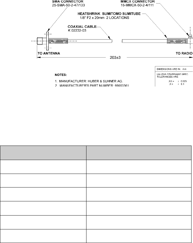
Antenna cable and connectors
The antenna cable and connector connects the antenna to the radio modem. RIM uses
the industry-standard MMCX connector for the RIM GPRS Radio Modem. The
MMCX connector is very small, and it has the mating force to withstand heavy
vibration.
Typically, an antenna does not plug directly into a RIM GPRS Radio Modem. Instead,
a cable is used between the radio’s antenna connector and a second connector at the
device’s outer casing. This allows the antenna to be removed from the system without
opening the device, and it eliminates a source of strain on the radio’s MMCX
connector.
The antenna cable that you use should have low loss, an impedance of 50 Ω, and an
MMCX plug that mates with the RIM GPRS Radio Modem’s MMCX jack. The other
end of the cable can be any connector with an impedance of 50 Ω. An SMA screw-on
connector is suitable and widely available. TNC connectors are also suitable, but they
are larger than SMA connectors.
The following cable is included with the Integrator Kit:
Note: The 6-pin interface cable supplied with the Integrator Kit is a 76.2 mm (3.0") long Flat Flex
Cable (FFC) Jumper with 1.00 mm centerline spacing and same side conductive surfaces, Parlex
part number 100-6-76-B.
This cable can plug into a matching 6-position 1.0 [0.039] horizontal FPC connector. A variety of
connectors are manufactured by AMP/Tyco Electronics, including AMP part number 487951-6.
For information about each connector, including mechanical drawings, visit the manufacturer's
web site (www.amp.com), or contact RIM (oemsupport@rim.net) for help with selecting an
appropriate connector for your application.
Note: The antenna cable supplied with the Integrator Kit has an MMCX connector on one end
and an SMA connector on the other. The cable is built with strain reliefs to prevent damage.
Chapter 4: Integrating the radio modem
44 RIM GPRS Radio Modem
Integrator Kit antenna cable
Huber & Suhner provides antenna cables and connectors. The parts described below
have an impedance of 50 Ω and are suitable for use with the RIM GPRS Radio
Modem.
Contact:
Part number Cable or connector
11MMCX-50-2-1C/111 Straight MMCX connector
16MMCX-50-2-1C/111 Right-angle MMCX connector
25SMA-50-2-25/111 SMA connector
EZ Flex 405 Low-loss matching (50 W) cable
133REEZ4-12-S2/1216 8” cable, straight MMCX to SMA
133REEZ4-12-S2/1699 8” cable, right-angle MMCX to SMA
Huber & Suhner
Essex Junction, VT, USA
phone: (802) 878-0555
fax: (802) 878-9880
web site: www.hubersuhnerinc.com
Huber & Suhner
Kanata ON, Canada
phone: (800) 627-2212
fax: (613) 596-3001


Chapter 5: Power Requirements
46 RIM GPRS Radio Modem
Load specifications
The RIM GPRS Radio Modem draws its power in bursts; the power required changes
rapidly depending on whether the radio is transmitting, receiving, or idle.
Power supply parameters
The RIM RIM GPRS Radio Modem requires a clean, stable 3.5 to 4.75 volt source that
is capable of delivering a one-second burst of up to 2 A when it is required by the
transmitter. RIM recommends that you design a more robust power supply that can
provide adequate power under such non-ideal conditions as an improperly matched
antenna, under which this burst could be as high as 2.2 A.
If you want your RIM GPRS hardware integration to be fully compatible with the RIM
902M and RIM 802D radio modems, make sure that the power input to the radio
modem is above 4.1 Volts. Please contact the RIM OEM Engineering Development
team for further details on backwards compatibility.
Ripple specification
For best performance, RIM recommends ripple of less than 15 mV peak-to-peak
(measured at the radio end of the connector) across the frequency range 60 Hz to
1 MHz. The maximum ripple at the connector that can be tolerated is 20 mV
peak-to-peak.
Except in special cases where there are several sources of ripple, you should measure
the ripple with an oscilloscope set to 1-MHz bandwidth; the peak-to-peak value is not
to exceed 15 mV.
You can place a passive LC (series L, shunt C) power filter between your power
supply and the RIM radio modem to reduce ripple at the radio connector. The radio
modem already has approximately 70 µF of on-board shunt capacity. The inductor
cannot exceed 100 µH (otherwise, transients could reset the radio), it must be rated to
pass the maximum DC current of 2.2 A supply current at all temperatures, and its
resistance must be low enough to guarantee minimum voltage of 3.5 V to the radio
modem at 2.2 A.
Note: If there are several ripple components, or if ripple is measured with a larger (typically
20-MHz) bandwidth, the ripple appears to be worse than it is. If the ripple is still below 15 mV
under these conditions, it meets the ripple specification.
Power requirements
Integrator Guide 47
Power requirements
The RIM GPRS Radio Modem requires a clean power source that is capable of
delivering bursts of high current. You can provide this power source through the
following sources:
•a rechargeable battery pack or single-use batteries
•a plug-in power supply unit
•an automotive supply
These sources are discussed below.
Batteries
If the RIM GPRS Radio Modem is integrated into a handheld device, it can be
powered by batteries. This technology is easily available, and it eliminates the need
for power supply components, such as voltage regulators.
Rechargeable batteries
Nickel cadmium
For battery-operated applications that require a wide operating temperature range,
RIM recommends using rechargeable nickel cadmium (NiCad) batteries to power the
RIM GPRS Radio Modem. You can also successfully use nickel metal hydride (NiMH)
and lithium ion (Li+) cells. However, many of these cells work poorly at temperatures
below freezing. Batteries specifications should be obtained from the manufacturer.
The cells that you use must be able to meet the radio modem load specifications (refer
to page 46); they must be able to provide 2.0 A (at 4.2 V) for transmission.
Rechargeable cells vary considerably; even if two cells have the same published
capacity, one might be less efficient than another when the radio transmitter is turned
on. This is because some batteries have a higher equivalent series resistance (ESR) at
high current drain. The ESR should be low enough that the battery can supply the
transmission current required without a large voltage drop.
Alkaline
You can also use rechargeable alkaline batteries. These cells are typically rated for
about 25 discharge cycles, far fewer than NiCads, but they provide longer life than
NiCads. For the first five to ten cycles, you will receive about 70 to 80 percent of the
battery life that you would expect from a single-use alkaline cell. After 25 discharges,
this number may drop to 50 percent.

Chapter 5: Power Requirements
48 RIM GPRS Radio Modem
Single-use batteries
Of the single-use cells, only alkaline and lithium cells provide the high current
necessary for transmission. However, AA alkaline cells are likely the best choice. They
are inexpensive, widely available, and provide an excellent power source. Alkaline
cells typically run for approximately four times longer than similar-size NiCad cells
and for approximately three times longer than similar-size NiMH cells.
Plug-in supplies
A plug-in supply converts normal AC power (usually 110 V or 220 V) into a steady
DC source that can be used instead of batteries. You must design your plug-in supply
to make sure that voltage spikes, lightning, and other power fluctuations cannot
damage the radio modem. To keep the inputs within the limits given in the radio
modem load specifications (refer to page 46), you can add transient voltage protection
zener diodes or other spike arrestor circuits. These should have a value of 20 V and be
placed on the supply side of the regulator circuit.
Preliminary indications suggest a supply capable of providing at least 3.5 V and rated
for 2.2 A peak current is recommended. Final numbers are yet to be determined.
Automotive supplies
If you plan to power the RIM GPRS Radio Modem from an automotive supply, you
must take steps to protect the radio modem from the intense power fluctuations that
occur when an automobile starts. You should use a circuit that consists of inductors,
transorbs and voltage regulators to make sure that the radio modem is protected from
these power fluctuations.
Warning: You must take precautions with alkaline rechargeable batteries. These cells are not
intended to be used to their full capacity, so their actual useful runtime is closer to 30 to 40
percent of a single-use alkaline cell, and they require the user to pay closer attention to the
battery state. If you fully discharge a rechargeable alkaline battery, you may only get five
recharges before the capacity decreases to the point where it can no longer be used.
Warning: RIM strongly discourages the use of general-purpose carbon-based batteries; this
type of battery cannot supply the power required by the transmitter. These cells are more
suited to flashlights and other products that do not have a load characteristized by bursts. If a
carbon-based battery is used, the voltage drops below the minimum power required under
load almost immediately following a radio transmission, which resets the radio each time it tries
to transmit.
You should recommend that users of your product use single-use batteries that are clearly
identified as alkaline.
Automotive supplies
Integrator Guide 49
Commonly, in automotive applications, voltages may be as high as 70 V on the
battery, especially on startup. Commercial automotive adapters are available that
safely convert the 12 V automotive supply to a regulated supply suitable for
operating the RIM GPRS Radio Modem.
Chapter 5: Power Requirements
50 RIM GPRS Radio Modem


Chapter 6: Interface specification
52 RIM GPRS Radio Modem
RIM GPRS Radio Modem interface
The asynchronous serial interface on the RIM GPRS Radio Modem operates at 3.0V,
which means that it is compatible with many existing system designs.
The radio modem can be controlled by a wide variety of microcontrollers and
microprocessors, such as the Intel 8051 or 80386, or Motorola 68000. In most cases, the
RIM GPRS Radio Modem can be connected directly to a micro-controller, or through a
Universal Asynchronous Receiver/Transmitter (UART) to a microprocessor data bus.
If the radio modem will be connected directly to a PC or other RS-232 device, an
interface must be provided to convert the signal voltage to the higher values required
by an RS-232 device.
The RIM GPRS Radio Modem is compliant with GSM Phase 2/2+ specifications. For
detailed information on the AT command structure, please refer to the RIM GPRS
Radio Modem AT Command Reference Guide included in the Integrator Kit.
AT Commands
Command Description
V.25ter The V.25ter commands correspond to the basic commands of AT
Hayes-compatible modems applicable for GSM 07.07. These
commands include answering incoming calls, switching modes,
and redialling.
GSM 07.07 The GSM 07.07 commands are used to remotely control GSM
functionality, including phone book functionality. These
commands include selecting bearer service types, entering PINs,
and changing passwords.
GSM 07.05 for SMS The GSM 07.05 commands are used to perform short message
service (SMS) and CBS related operations for both Text and PDU
modes. These commands include deleting, transmitting, and
saving SMS messages.
GSM 07.07 for GPRS The GSM 07.07 for GPRS AT commands are required for all GPRS
functionality, including PDP context definitions and activations
quality of service (QoS) definitions and requests GPRS attaches and
detaches, PDP address retrieval GPRS Mobile Station class retrieval
event reporting, network registration status retrieval, and SMS.
SIM interface pins
Integrator Guide 53
SIM interface pins
This section describes the purpose of each of the 6 lines that comprise the SIM
interface to the 1902G and 1802G radio modems. All SIM Interface lines are 3.0 volt
logic. The 1902G and 1802G radio modems' software polls the SIM card to confirm its
presence.
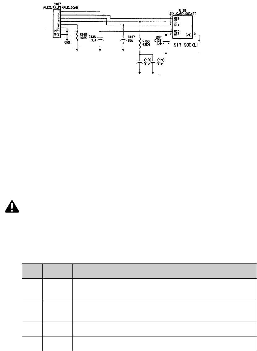
The following diagram shows an example of how the SIM was incorporated onto the
RIM Integrated Test Board:
Note: The SIM interface Pins only apply to models with off-board SIM cards.
Note: For proper operation, the SIM connector cable should be no more than 10cm long.
The VPP line on the SIM card connector can be shorted with the VCC line to continue proper
operation.
Pin Description
1 VCC.
This line supplies the SIM with power. Verify that it leads to the VCC pin of the SIM
card connector. It may be necessary to filter noise on the line to prevent a fault from
occurring. Please refer to the diagram in the next section as an example.
2 Reset.
This is an output from the radio. Verify that it leads to the Reset pin of the SIM card
connector.
3Clock.
This is an output from the radio. Verify that it leads to the Clock pin of the SIM card
connector.
4Input/Output.
This is a bidirectional line between the SIM card connector and the RIM GPRS Radio
Modem. Verify that it leads to the I/O pin of the SIM card connector.
5SIM Detect.
The active state of this line is high. This line should be asserted in order to ensure
the radio modem can detect the SIM card.
6Ground.
This is an input to the radio. Short this line to the GND pin of the SIM card
connector.
Chapter 6: Interface specification
54 RIM GPRS Radio Modem
SIM test board integration
Radio Interface Pins
This section describes the purpose of each of the 22 lines that comprise the radio
interface to the RIM GPRS Radio Modem.
Serial port
The serial port uses pins 13 and 22 to transmit and receive and may be used only by a
custom application that resides on the radio modem itself (not by AT and data traffic).
Flow control lines are provided for only the primary serial port.
Pin descriptions
The following table lists each pin and describes it in detail.
Note: The symbol ~ before the label indicates that line is an active low digital signal.
Pin Label Description
1 MIC N Analog Microphone Input Negative
This is an analog input to the radio.
2 MIC P Analog Microphone Input Positive
This is an analog input to the radio.
3 SPK N Analog Speaker Negative
4SPK PAnalog Speaker Positive

Radio Interface Pins
Integrator Guide 55
5 AGND Analog Ground
This is an analog ground for the radio.
6COV Coverage
This line is a digital output from the radio.
The active state of this line is high and indicates that the radio modem is
in network coverage, as determined by the presence of a signal from the
network base station.
When the radio modem does not have contact with the wireless network,
this line is low.
7, 8 — Power supply
These pins supply power to the radio. Since the current requirement
during transmission exceeds the current rating of a single line, both lines
7 and 8 should be connected to the power supply. Supplying power to
these two lines allows the radio to turn on.
9GND Ground
This line should be tied to the system ground of the computing device to
ensure proper operation. Pin 18 should also be connected to ground.
10 TURNON Turn Radio On
This line is an input to the radio.
This line turns on the radio unit. It is a digital signal that eliminates the
need for an on/off switch for the power supply to the radio modem. This
is a 3.0 V input to the radio, and is not 5.0 V tolerant.
Refer to "Turning off and turning on the radio" on page 57 for more
information.
11 ONI On Indicate
This line is a digital output from the radio that indicates that the radio is
on and operational.
This line can be used by a computing device to qualify the handshaking
outputs on the serial interface. If CTS is low, and ONI is high, then the unit
is ready to receive data, but if CTS is low and ONI is low, then the radio
modem is not ready to receive data because it is off.
When ONI is low, all inputs to the radio modem should be held low or
disconnected. Otherwise, power is consumed and wasted.
12 TRI Transmit Indicate
The active (radio transmitting) state of this line is high.
This output from the radio modem is asserted while the radio is
transmitting a packet to the network base station. TRI has a built-in
current limiter that enables it to directly drive an LED , which provides
real-time visual feedback that the radio is transmitting packets. If this is
not necessary, you can leave the line disconnected.
This line supplies 3 mA to a standard LED, and is short-circuit protected.
This line is low when the radio modem is off.
Pin Label Description

Chapter 6: Interface specification
56 RIM GPRS Radio Modem
13 RX2 Secondary Receive
This line is meaningful only as part of a debug port primarily for RIM
internal use.
14 ~RI ~Ring Indicate
This line is an output from the radio modem. It indicates an incoming call
on the serial line.
When ~DTR is not asserted (high), the radio modem asserts ~RI (low) to
indicate that it has data waiting for the computing device. The radio
modem does not transfer the data until ~DTR is asserted (low). This line
can be used to wake up a suspended computing device when the radio
modem needs to communicate with it. If ~DTR is already asserted (low)
when the radio modem has data to send the computing device, ~RI is not
asserted.
15 ~CTS ~Clear To Send
This line is a digital output from the radio modem to the computing
device. The active (clear to send) state of this line is low.
When asserted low by the radio modem, this line indicates that it is ready
to receive data from the computing device. While this line is high, any
data sent from the computing device to the RIM GPRS Radio Modem may
be lost. This line is a flow control mechanism that is normally reacted to
by the UART in your serial communication system. If you do not plan to
use it, leave ~CTS disconnected.
16 ~RTS ~Request To Send
This line is an input to the radio modem. The active, request to send, state
of this line is low.
This line should be asserted low by the computing device to indicate that
it is ready to receive data from the radio modem. This is a flow control
mechanism that is normally handled by the UART in your serial
communication system. If you do not connect this line to your UART, it
must be tied low so that it is permanently asserted and enables
communication.
If your device buffer overflows, it should set RTS inactive to signal the
radio modem to pause sending data. There might be a 16-byte overrun
after the RTS line is made inactive, so your device should set RTS inactive
at least 16 bytes before any critical buffer overflows.
17 ~DSR ~Data Set Ready
This line is a digital output from the radio modem.
The active, data set ready (DSR), state of this line is low. Your computing
device can use DSR as a confirmation that the radio modem knows the
state of the terminal..
18 GND Ground
This line should be tied to the system ground of the host unit to ensure
proper operation. Pin 9 should also be connected to ground.
Pin Label Description

Turning off and turning on the radio
Integrator Guide 57
Turning off and turning on the radio
To determine the current state of the radio, observe the ONI line. If ONI is high, the
radio is on or is in the process of shutting down. If ONI is low, the radio is off or in the
process of turning on. The TURNON pin is a digital signal that turns the radio on and off.
It eliminates the need for a power switch across the power supply to the radio. TURNON
also enables and disables the serial port.
19 ~DTR ~Data Terminal Ready
This line is a digital input to the radio.
The active, data terminal ready (DTR), state of this line is low, and indicates
that the computing device is ready to receive data from the radio modem.
De-asserting this line high turns communication off; the radio modem
does not attempt to deliver data to the computing device until ~DTR is
again asserted low.
If you do not intend to use ~DTR, tie it to ground to ensure that it is always
asserted during radio modem operation.
This line should be deasserted when the radio modem is off. Driving ~DTR
low when the radio modem is off will consume unnecessary power.
20 TX Transmitted data
This is an input to the radio. Its idle (no serial transmit activity) state is
high.
This line is an asynchronous serial input to the radio modem, and should
be connected to the host terminal's Transmit Data output. This line carries
data at a maximum of 115 200 bits per second. Parameters are 8 bits, No
parity, 1 stop bit. This baud rate can be changed using the
AT+IPR=<rate> AT command.
21 RX Received data
This line is an output from the radio modem. Its idle (no serial receive
activity) state is high.
This line is an asynchronous serial output from the radio modem, and
should be connected to the host terminal’s Receive Data input. This line
carries data at at a maximum of 115 200 bits per second. Parameters are
8 bits, No parity, 1 stop bit. The baud rate can be changed using the
AT+IPR=<rate> AT command.
22 TX2 Secondary Transmit
This line is for RIM internal use only.
Pin Label Description
Warning: All unused inputs to the radio should be tied to ground, and any unused outputs
from the radio should be left disconnected.
Chapter 6: Interface specification
58 RIM GPRS Radio Modem
Turning on the radio
You can turn the radio modem on by setting TURNON to high.
The following considerations are related to turning on the radio:
•During the RIM GPRS Radio Modem’s startup procedure, which can take several
seconds, all changes to TURNON are ignored by the operating system.
•Do not use TURNON to indicate radio status. ONI must be used as the indicator of
the radio status. It is possible for the radio to be off even though TURNON is
asserted. In this case, you can turn on the radio by setting TURNON low and then
high again.
•If the radio fails to respond to a high TURNON line, the radio may require service or
the power supplied to the radio may be too low for proper operation.
Turning off the radio
The RIM GPRS Radio Modem requires a controlled shutdown. You can turn the radio
modem off by de-asserting TURNON.
The following considerations are related to turning off the radio:
•During the RIM GPRS Radio Modem’s shutdown procedure, which can take
several seconds, all changes to TURNON are ignored by the operating system.
•Do not use the TURNON state to indicate radio status. ONI must be used to indicate
radio status. It is possible for the radio to be on even though TURNON is de-asserted.
In this case, you can turn off the radio by setting TURNON high and then low again.
•To make sure that power consumption is reduced to the lowest possible levels, all
inputs to the radio should be low when the radio is turned off.
•Data that has been received by a RIM GPRS Radio Modem from the network, but
has not been transferred to the computing device, will not be saved. The data will
be lost when the unit begins shutdown or is turned off.
•It is only necessary to remove power from pins 7 and 8 if the application is very
power constrained.
Resetting the Radio
RIM recommends that you incorporate a method to remove power from pins 7 and 8
on the radio modem during the development and prototype phase. This will enable
the device to perform a hard reset of the radio modem, which can be useful in some
debugging testing situations.
Loading firmware (optional)
Integrator Guide 59
Loading firmware (optional)
RIM firmware controls the operation of the radio modem. RIM is committed to the
quality of its firmware, and may periodically make improvements or optimizations to
it. The radio modem is designed so that loading revised firmware is not required; two
RIM GPRS radio modems with different firmware revisions will always be able to
communicate with each other, and with the same fixed servers, through the wireless
network. Nevertheless, you may choose to design your application in such a way that
allows the RIM firmware to be updated after your product is deployed in the field.
Because of its large size, firmware cannot be updated over the air. If you decide to
implement the ability to update the firmware after the radio modem is deployed, RIM
can provide a command-line programming utility that loads firmware into the radio
modem. If your device is not MS-DOS-based, the programming utility must reside on
a PC or laptop that is connected through its COM port to the radio modem’s RX and TX
lines. This means that the RX and TX lines are brought out to an external connector,
and a switch is required to select whether the radio modem is connected to your
processor or to the external programming computer. Other lines that are required
during reprogramming are DTR (must be asserted low) and GND.
This external serial port can also be useful for FCC certification testing, and it is highly
recommended that this be incorporated into at least one device designated for testing
purposes.
Chapter 6: Interface specification
60 RIM GPRS Radio Modem

Chapter 7: Antenna selection
62 RIM GPRS Radio Modem
Introduction to antenna terminology
This section introduces some of the terminology that is used to describe antennas, and
expands on the summary of antenna requirements that are described below (refer to
page 64).
Gain and ERP
Antennas produce gain by concentrating radiated energy in certain areas, and
radiating less energy in other directions. The amount of gain depends on the radiation
pattern, antenna match, and antenna efficiency. Antenna gain is given as a rating of
the maximum increase in radiated field energy density relative to a dipole antenna,
expressed in decibels of power gain (dBd).
A dipole is a balanced antenna consisting of two radiators that are each a
quarter-wavelength, making a total of a half-wavelength. The widespread use of
half-wave dipole antennas at VHF and UHF has led to the use of a half-wave dipole as
the reference element.
At the antenna port, the output power of the RIM GPRS Radio Modem is as high as
1.0 W at the antenna port. The antenna gain (or loss) results in an increase (or
decrease) in this value. The actual output from the antenna is called the Effective
Radiated Power (ERP). For example, if the radio modem delivers 2.0 W of power to a
2.3 dBd gain antenna, the ERP is 2.0 ×10^(2.3÷10) = 3.4 W, the actual power radiated by
the antenna in the direction of maximum gain and polarization.
Impedance matching, return loss, and VSWR
The antenna, cables, and connectors in a radio frequency system must all possess the
same impedance. The impedance required by the RIM GPRS Radio Modem is 50 Ω,
which is a widely-available industry standard. Any deviation from this value may
result in impedance mismatch and signal loss.
Impedance mismatch can also be caused by cable connections, cable lengths, and
imperfections in the cables and connectors. The mismatch causes some of the radio
frequency energy to be reflected back from the mismatch location. This reflection
interferes with the signal and reduces its amplitude, which results in power loss.
Antenna mismatch can be expressed as a Return Loss (RL), which is the ratio of
reflected power to the incident power, expressed in decibels.

Selecting an antenna
Integrator Guide 63
Equation 1: Return Loss
The Voltage Standing Wave Ratio (VSWR) is another way to express the ratio of
incident power (from the radio modem) to reflected power (into the radio modem).
Equation 2: VSWR
VSWR=1 or RL=-∞dB is a perfect match. In practice, imperfections are inevitable,
which means that VSWR will be greater than 1 and RL will be a negative number.
VSWR and RL normally vary as a function of frequency.
Antenna size
The optimal antenna radiation efficiency is produced by an antenna measuring one
wavelength, l. The value of l for the RIM GPRS Radio Modem is calculated by
dividing the speed of light c = 3 x 10⁸ m/s by the center frequency.
Antenna lengths of λ/2, λ/4, and λ/8 also work well, and usually result in a relatively
well matched antenna. λ/2 or λ/4 can be electrically “shortened” by adding load
matching elements to control the antenna match. However, this shortening will
reduce the antenna efficiency and, therefore, the effective radiated power.
Selecting an antenna
The antenna is one of the most important components of a wireless communication
system. The right antenna will maximize the coverage area of the RIM radio modem.
The antenna that you choose should suit your project’s needs. There are many
different antenna types and options that will meet your engineering and user
requirements and remain within budget constraints. We strongly recommend that
you use an experienced antenna provider in order to realize the highest gain possible.
A well-designed antenna solution will maximize your application’s efficiency,
coverage area, and battery life.
RL =×
10 10
log P
P
reflected
output
VSWR =
+1P
P
1 - P
P
reflected
output
reflected
output
Chapter 7: Antenna selection
64 RIM GPRS Radio Modem
Antenna manufacturers have designed and manufactured a wide variety of antennas
for use on the GPRS network and for other radio-frequency (RF) systems operating in
the same frequency range. RIM does not recommend specific antennas because the
choice of antenna is application-dependent.
An antenna’s performance depends on its configuration and environment; the same
antenna behaves differently from device to device, even if these devices use the same
RIM radio modem. For example, a magmount antenna might be suitable for some
applications, because it includes a magnetic base that clamps the antenna onto a metal
surface. This surface is called a ground plane, and it reflects electromagnetic radiation
that would otherwise be lost to the antenna. This reflection effectively doubles the
length of the antenna by creating a virtual “mirror image” of the antenna beneath the
plane.
Antenna requirements
The antenna system used with the RIM GPRS Radio Modem has the following
minimum requirements:
•For the RIM GPRS Radio Modem hardware integration to be fully compatible
with the RIM 902M and RIM 802D radio modems, the antenna must be modular.
•GPRS has several frequency bands, 1900, 1800, 900, and 850, each of which
requires its own antenna.
•GPRS, Mobitex, and DataTAC networks have different center frequencies. If the
same antenna is used for all three networks, receiver sensitivity is reduced.
Contact the RIM OEM Engineering Development team for more information on
backward compatibility.
•The RIM GPRS Radio Modem requires an impedance of 50 Ω.
Antenna design considerations
Proper antenna positioning maximizes the gain provided by the antenna. When you
determine the proper antenna position, consider the environment in which the device
will be used. Physical devices can vary significantly, and incorporating the antenna is
an integral part of a successful design.
When you are designing an antenna, you should consider the following issues:
•vertical polarization
•proximity to active electronics
•transmit interference
•device position
•antenna cable
Antenna design considerations
Integrator Guide 65
These issues are discussed below.
Vertical polarization
Because the GPRS network is based on a vertically polarized radio-frequency
transmission, the application’s antenna should be oriented vertically and upward
when the radio modem is in use. In small, hand-held devices, a user-friendly design
would allow the antenna to be folded out of the way when it is not in use.
Proximity to active electronics
You should position the antenna as far from the computing device’s active electronics
as possible. Metal construction in a computing device’s case and internal components
may attenuate the signal in certain directions, which reduces the radio modem’s
sensitivity and transmit performance when the computing device is held or
positioned in certain orientations. However, the judicious use of metal in the
construction of a ground plane for an antenna can significantly improve the antenna
gain and the system’s coverage.
Transmit interference
To prevent interference from the antenna into the radio modem during transmit, the
antenna must be placed a minimum 2 cm (0.8”) away from the radio modem. For best
performance, the antenna should be placed more than 5 cm (2”) away from the radio
modem.
Device position
If the computing device is designed to sit on a surface, the antenna should be as far
from the bottom of the device as possible. This reduces radio-frequency (RF)
reflections when the device is placed on a metal surface.
When the computing device is hand-held or is worn next to the user’s body, the
antenna should be positioned to radiate away from the body. Otherwise, the body
absorbs the radiated energy and the effective coverage area of the radio is reduced.
Positioning the antenna away from the body also helps the device meet the FCC’s RF
exposure (SAR/MPE) requirements.
Chapter 7: Antenna selection
66 RIM GPRS Radio Modem
Antenna cable
For best results, the antenna should be connected directly to the antenna cable. If you
require an extension cable, it should be low loss, as short as possible, and have an
impedance of 50 Ω. You must use a proper matching connector, because each
connector in the signal path introduces a return loss and reduces performance.
Additional notes
The following additional notes are provided courtesy of Larsen Antenna
Technologies:
“There are a number of critical issues to consider when integrating antennas into
portable RF systems. It is important to make allowances early in the design process to
optimize performance and provide flexibility in antenna choice. Generally, it is
prudent to position the antenna “up and away” from the radio modem and printer
motors to maximize noise reduction and receiver desensitivity. Other “high noise”
areas to be avoided include displays and keypads that can seriously degrade antenna
performance. Advances in antenna shielding techniques may also be incorporated to
retain the integrity of the system.
“Mechanical issues for an integrated antenna revolve around proper cable routing
and use of service loops to provide uninhibited antenna rotation if needed. The ability
to position the antenna in a manner which will result in antenna deformation, impact
resistance and aesthetic requirements must also be considered to design a workable
form factor. The option to position the antenna vertically when in use so that
performance is optimized is another consideration which can be limiting and a true
consideration when choosing to use off-the-shelf solutions.
“Custom antenna solutions may be worthy of consideration for some projects. In
some applications, custom designed antennas have shown performance increases of
up to 2 dB when compared to quality off-the-shelf solutions. The cost of a custom
design and resulting production can be as cost efficient as an off-the-shelf solution for
projects requiring quantities as low as 20,000 antennas. “The use of state-of-the-art
antenna theory, printed circuit technology, and application of evolving concepts can
produce antennas with reduced sized without compromising performance.
“Examining the options available, and choosing an antenna early in the development
process, can only benefit the performance and aesthetic appeal of a product. The
engineering staff at Larsen Antenna Technologies are experts in this field with over 30
years of experience in helping OEMs reach their antenna design and production
objectives.”

Shielding
Integrator Guide 67
Shielding
RIM GPRS Radio Modem’s electrical design provides high immunity to
radio-frequency (RF) noise, also called electromagnetic interference (EMI). The metal
casing also acts as a shield that helps to minimize the effect of RF interference that
originates in the computing device to which it is attached. The metal casing also
prevents the RIM radio modem from emitting RF energy into the computing device
and disrupting the computing device’s operation.
Consequently, you do not need to provide any additional RF shielding between the
radio modem and a computing device, unless the environment contains an extreme
level of RF noise. In fact, additional RF shielding is less important than making sure
that the radio modem’s power supply is free of high-frequency electrical noise.
The antenna must be positioned so that the radiated energy is directed away from the
computing device. If your application does not permit this positioning, RF shielding
may be required between the antenna and the computing device.
Note: Circuits with a high impedance, and sensitive analog circuits, are especially vulnerable to
nearby radio frequency emissions, and may need to be shielded. Circuits like CRTs and LCD
display drivers are most often affected.
Chapter 7: Antenna selection
68 RIM GPRS Radio Modem


Chapter 8: Certification
70 RIM GPRS Radio Modem
FCC radio frequency exposure rules
Based on FCC rules 2.1091 and 2.1093 and FCC Guidelines for Human Exposure to
Radio Frequency Electromagnetic Fields, OET Bulletin 65, and its Supplement C, all
integrations of the RIM GPRS Radio Modem are subject to routine environmental
evaluation for radio-frequency (RF) exposure prior to equipment authorization or
use.
For portable devices, defined in accordance with FCC rules as transmitting devices
designed to be used within 20 cm of the user body under normal operating
conditions, RF evaluation must be based on Specific Absorption Rate (SAR) limits in
W/kg. SAR is a measurement of the rate of energy absorption per unit mass of body
tissue.
For mobile devices, defined as transmitting devices designed to be generally used
such that a separation distance of at least 20 cm is maintained between the body of the
user and the transmitting radiated structure, the human exposure to RF radiation can
be evaluated in terms of Maximum Permissible Exposure (MPE) limits for field
strength or power density in mW/cm2.
Complying with FCC SAR/MPE guidelines
Antenna
If the RIM GPRS Radio Modem is integrated in a vehicle, and the Eclipse magmount
antenna is used, the MPE limits are not exceeded provided that the antenna is
installed at least 20 cm from any edge of the vehicle rooftop. This can be accomplished
by making it mandatory for customers to put a prominent warning in their user
manual, which warns installers to properly mount the antenna in the centre of the
vehicle rooftop. The user should also be warned to maintain the minimum required
distance from the antenna.
The submission to the FCC should include end product information, end product
SAR/MPE test report, and a reference to the RIM module FCC ID for all other Part22
and 24 requirements.
Note: The FCC grant for the RIM GPRS Radio Modem does not limit or restrict it to operating in
vehicle-mount configurations. However, in a non-vehicle situation you may need to provide
semi-fixed installation procedures for magmount antennas to make sure that the MPE
separation distances are met for satisfying grant conditions and to overcome mobility issues
caused by such antennas.
Warning: It is mandatory for portable end-products, such as handheld and body-worn devices,
to comply with FCC RF radiation requirements’ SAR limit.
Complying with FCC SAR/MPE guidelines
Integrator Guide 71
For information on labs for SAR/MPE testing, visit http://www.rim.net/oem.
During the SAR/MPE testing, the RIM testing software resides on an external
computer that must be able to directly communicate with the radio modem. The
device that you submit can meet this requirement one of the following ways:
•The device you submit for testing must have an external connector that can be
used to connect the radio modem to a computer.
•If your device can run DOS-based programs, RIM can provide a DOS-based
utility that joins two COM ports. This utility is useful if the radio modem might
be connected to a handheld device’s internal COM 4 port.
•The device has an external RS-232 serial connection to COM 1.
•The device has a virtual link between the two COM ports, so that an external
device connected to COM 1 can communicate with the radio modem connected to
the internal COM 4, which eliminates the need to remove the radio from the
handheld device.
SAR and MPE limits
Guidelines
RF exposure distance is based on normal operating proximity to the user’s or nearby
persons’ body. This distance is measured from any part of a radiating structure,
which is generally the antenna, to the closest body part. If antennas other than those
tested by RIM are used, a set of tests must be performed to determine the passing
distance that meets the SAR exposure limits for handheld, body-worn, and portable
devices, or MPE exposure limits for vehicular and mobile devices.
Operating manual compliance statement
For mobile and vehicular devices, Integrators should include a statement in their
operation, user, and/or installation manual that informs users of RF exposure issues
and make sure that bystanders keep a passing distance from the antenna while it
General Population/
Uncontrolled
exposure
1.6 W/kg for partial body exposure, averaged over 1 g of tissue
4 W/kg for hands, wrists and feet averaged over 10 g of tissue
Note: The 1.6 W/kg limit applies for most RIM radio modems.
Occupational/
Controlled exposure
8 W/kg for partial body
20 W/kg for hands, wrists and feet.
MPE PCS 1900 MHz band: 1 mW/cm2
GSM 850 MHz band: 0.56 mW/cm2
Chapter 8: Certification
72 RIM GPRS Radio Modem
transmits. Integrators should provide instructions or diagrams in the manual for
proper antenna mounting and position, when applicable, to make sure that the
antenna is a safe exposure distance to the operator and nearby persons.
For handheld, body-worn, and portable devices, separate FCC approval is required to
be in compliance with FCC RF exposure guidelines with respect to the SAR limits.
Labelling
Compliance with respect to SAR limits which satisfy MPE limits would not require
warning labels, but you can use an RF radiation warning label to alert the user or
nearby persons about abnormal usage conditions.
Installation instructions should, at a minimum, specify the correct mounting
procedure on a ground plane, and recommend positioning the antenna so that the
minimum distance is kept from any edge of the vehicle rooftop.
For more information
Sections 2.1091 and 2.1093 of the FCC Rules, which govern RF exposure limits, are
available at:
web site: http://www.access.gpo.gov/nara/cfr/index.html
by searching for “47CFR2.1091” and “47CFR2.1093”.
Bulletin 65 and its Supplement C, issued by the FCC RF Safety Group (Office of
Engineering and Technology), is available at:
web site: http://www.fcc.gov/oet/info/documents/bulletins/#65
You can obtain further information concerning FCC regulations, including RF
exposure limits, by contacting the RF Safety Group:
phone: (202) 418-2464
email: rfsafety@fcc.gov
web site: http://www.fcc.gov/oet/rfsafety
You can also contact the FCC Call Centre:
phone: 1-888-CALL-FCC (1-888-225-5322)
You can contact the RIM Engineering Development:
phone: (519) 888-7465
email: oemsupport@rim.net


Chapter 9: Specifications
74 RIM GPRS Radio Modem
Power supply & typical current usage
RF properties
Serial communications
Other features
•ARM Processor running at 32.5 MHz
•Software can activate/deactivate radio
Power supply single power supply
Operating range 3.5 to 4.75V DC
Transmit mode up to 2 A (at 4.2V, output 1.0W)
1902 models 1802 models
Transmit
frequency
1850 - 1910 MHz
824 - 829 MHz
1800 MHz
890 - 915 MHz
Transmit power 1.0 W nominal maximum transmit power
at antenna port
1.0 W at 1800 MHz
2.0 W at 900 MHz
Receive
frequency
1930 - 1990 MHz
869 - 894 MHz
1805 - 1880 MHz
935 - 960 MHz
Receiver
sensitivity
typical -107 dBm
2.4% bit error rate (BER)
typical -107 dBm
2.2439% bit error rate (BER)
Multislot Class 88
Note: As defined in the GSM specifications, the radio modem’s transmitter can reduce output
power when it is near a base station.
Serial ports 3.0V asynchronous
Second 3-wire serial port (TX, RX, GND)
Link speed 1200 to 115 200 bps

Mechanical & environmental properties
Integrator Guide 75
•Flow control options:
•Hardware
•Xon/Xoff
•None
•Radio parameters stored at power down
•Terminal devices may power-down while radio-modem remains operational
•Fully shielded metal enclosure
Mechanical & environmental properties
Audio
Weight 36 g (1.2 oz), including case
Footprint 42.0 by 67.5 mm (1.65" x 2.66")
Thickness 8.4 mm (.33")
3.0V interface
connectors
22 pin Flexible Printed Circuit (FPC) connector
6 pin FPC connector (GS models only)
Antenna cable
connector
MMCX
Casing metal
Operating
temperature
-30°C to +75°C (at 5-95% relative humidity, non-condensing)
Storage
temperature
-40°C to +85°C
Note: The following audio functionality is not supported:
•automatic gain control (your design should include noise suppression)
•hands free
•echo cancellation
Chapter 9: Specifications
76 RIM GPRS Radio Modem
Gain setting
Frequency response (voiceband filter)
Input/output impedance
Signal to (noise + distortion)
Uplink 0 to 22.5 dB in step of 1.5 dB
Downlink -36 to 9 dB in step of 1.5 dB
0 -100 Hz max of -34 dB
200 Hz Typ of -1.1
300 - 3350 Hz min -0.2 dB
max 0.1 dB
3400 Hz typ of -0.7 dB
4000 Hz typ of -39 dB
>=4400 Hz -75 dB
Group
delay
500 - 2500Hz min 300 us
max 600 us
Input 124 kohm
Output minimum 330 ohm (single-ended)
15 ohm (differential)
maximum 470 pF (single-ended)
100 pF (differential)
Voiceband ADC minimum 69 dB (PGA=0dB)
typical 77 dB
Voiceband DAC minimum 47 dB (PGA=0dB)

Chapter 10
Glossary

Chapter 10: Glossary
78 RIM GPRS Radio Modem
Term Meaning
APN Access Point Name. GPRS network provider's name for a given external
network.
CBS Cell Broadcast Service. Unacknowledged general short messages to all
receivers within a defined geographical area
dB Decibel measures power based on a logarithmic scale. 10 dB = 10 times,
3 dB = 2 times, –10 dB = 0.1 times.
FPC Flexible Printed Circuit. The interface cable on the RIM GPRS Radio
Modem is made using this type of flat multi-conductor wiring. Also
known as FFC (Flat Flex Cable).
Gain In this document, refers to increase/decrease in radiated power.
GMSK The modulation scheme used by airlink communication on GPRS
communication. Allows theoretical data rates of 14.4 kbps per timeslot.
GPRS General Packet Radio Service. The IP-based data network that
supplements the existing GSM voice networks throughout the world.
GSM Global System for Mobile Communications. A second generation voice
communication network standard accepted throughout the world.
IP Internet Protocol. Standard network layer protocol used over many
networks including the GPRS network and the Internet.
MMCX The connector on the RIM GPRS Radio Modem to which an antenna
cable is connected.
Network Operator The corporation or agency that installs, maintains and authorizes use of
a GPRS network in a given area, usually within one country.
Noise Undesired, random interference combining with the signal. If the
device is not immune to noise, the interference must be overcome with
a stronger signal strength. Noise can be produced by electronic
components.
OEM Original Equipment Manufacturer. Usually implies that the “OEM
product” carries another manufacturer’s name. The RIM GPRS Radio
Modem is designed to be embedded in OEM terminals, PCs, and data
gathering equipment.
OSI The Open Systems Interconnection model allows different systems,
following the applicable standards, to communicate openly with each
another.

Integrator Guide 79
Polarity Direction of current flow. Connecting some cables with the wrong
polarity (i.e. backward) may damage the device.
QoS Quality Of Service.
Radio Modem A device that provides modulation and demodulation for a radio
frequency communications system.
Radiation In this document, refers to electromagnetic energy emitted in the radio
frequency (RF) band.
Return Loss A measure of antenna matching.
RF Radio Frequency.
RS-232 The standard asynchronous serial communications interface used by
most existing personal computers and mini-computers. Usually refers
to both the communications protocol and the electrical interface.
RSSI Received Signal Strength Indicator. A high RSSI represents a strong
signal received by the radio modem from the base station.
SIM Subscriber Identity Module. A SIM is necessary in order to activate a
GSM/GPRS device on the network.
SMS Short Message Service. Messaging services over the circuit-switched
GSM networks, up to a maximum of 160 characters.
TTL Transistor-Transistor Logic. Used in digital circuits. Low (0) is
represented by 0 V and High (1) by 5 V. The RIM RIM GPRS Radio
Modem uses 3.0V for High.
UART Universal Asynchronous Receiver/Transmitter. Used as an interface
between a microprocessor and a serial port.
VSWR Voltage Standing Wave Ratio. A measure of antenna matching. Refer to
"Antenna selection" on page 61 for more information.
Term Meaning
Chapter 10: Glossary
80 RIM GPRS Radio Modem
Integrator Guide 81
Index
Numerics
22-pin interface cable
connecting, 28, 34
illustration, 29, 35
6-pin connector
illustration, 34
6-pin interface cable
connecting, 33
A
AC outlet
connecting the test board, 31, 36
adhesive, industrial, 41
alkaline batteries
overview, 47
warning, 48
amplitude, 62
antenna, 64
cable, 43, 64, 66
connectors, 43
device position, 64
distance from radio modem, 65
ERP, 62
extension cables, 66
gain, 62, 65
ground plane, 64
impedance, 62
introduction to terminology, 62
magmount, 64
matching, 63
MMCX connector, 31, 36, 43
modularity, 64
MPE limits, 70
orientation, 65
position, 65
positioning, 31, 36, 64
proximity to active electronics, 65
radiation efficiency, 63
return loss, 62, 79
RF exposure requirements, 65
selecting, 63
shielding, 67
size, 63
SMA plug, 30, 36, 43
transmit interference, 64, 65
vertical polarization, 64, 65
VSWR, 62, 79
antenna cable
impedance, 43
in integrator kit, 43
Integrator Kit, 44
part numbers, 44
antenna development, overview, 23
arrestor circuits, 48
AT Commands, 52
attenuation, 65
audio
frequency response, 76
gain setting, 76
input/output impedance, 76
signal to (noise + distortion), 76
specifications, 75
automotive supplies
adapters, 48
power fluctuations, 48
B
batteries
alkaline, 47
equivalent series resistance, 47
nickel cadmium, 47
overview, 47
recommended, 48
single-use, 48
battery
conserving power, 16
bolts, 40
Index
82 RIM GPRS Radio Modem
C
cable
antenna, 66
radio interface, 41
SIM interface, 42
cables
serial, 41
certification
Industry Canada, 6
certification testing, 59
Class B compliance, 6
Clock SIM interface pin, 53
compliance
Class B, 6
FCC statement, 6
contacting RIM, 11, 20, 22
COV pin, 55
coverage
antenna positioning, 31, 36
CTS pin, 56
D
development process
antenna development, 23
FCC certification, 23
field trials, 23
power supply development, 23
printed circuit board development, 23
software development, 23
development process, overview, 21
dimensions, 39
DSR pin, 57
DTR pin, 57, 59
E
Effective Radiated Power, 62
environmental properties
specifications, 75
environmental testing, 38
equations
return loss, 63
VSWR, 63
equivalent series resistance, 47
ESR, 47
F
FCC
certification testing, 59
compliance statement, 6
interference requirements, 6
MPE limits, 70, 71, 72
SAR limits, 70, 71, 72
FCC certification, 23
getting started, 22
overview, 23
pre-design research, 22
Federal Communications Commission, 59
field trials, overview, 23
firmware, loading, 59
FPC cable, 41
frequency
VSWR, 63
frequency response, specifications, 76
G
G model test board, illustration, 33
gain, 65
gain setting
specifications, 76
General Packet Radio Service, 16
Global System for Mobile Communication, 16
GND pin, 55, 57, 59
GPRS radio modem
batteries, 47
bottom casing, 41
environmental testing, 38
GSM compliance, 52
integration overview, 38
integration possibilities, 15
MMCX jack, 30, 36
mounting, 39
mounting methods, 40, 41
noise immunity, 15
operating temperature, 38
power requirements, 46, 47
power supply parameters, 46
radio interface, 54
receiver sensitivity, 15
serial interface, 52
single board design, 16
size, 16, 39
specifications, 74
storage temperature, 38
transmitter, 16
GPRS radio modem specifications
dimensions, 39
weight, 38
GPRS, countries with, 17
Ground SIM interface pin, 53
GS model test board, illustration, 28
GSM, 16
H
headset
Index
Integrator Guide 83
connecting, 31, 36
I
illustrations
22-pin interface cable, 29, 35
6-pin connector, 34
antenna MMCX connector, 31, 36
FPC interface cable specifications, 42
G model test board, 33
GS model test board, 28
Integrator Kit antenna cable, 44
radio modem underside, 34
SIM card holder, 30
SIM test board integration, 54
SMA connector, 31, 36
test board underside, 30
impedance, 43, 62
industrial adhesive, 41
Industry Canada
certification, 6
Class B compliance, 6
input/output impedance, specifications, 76
Input/Output, SIM interface pin, 53
integration
GPRS radio modem, 15
illustrated, 21
overview, 38
process overview, 21
integration process
antenna development, 23
FCC certification, 23
field trials, 23
power supply development, 23
printed circuit board development, 23
software development, 23
Integrator Kit
content, 22
overview, 20
interface
connecting to, 41
test board, 27
UART, 79
interface cable
22-pin, 28, 34
6-pin, 33
SIM, 42
specifications, 42
interference
FCC requirments, 6
shielding, 67
L
LED indicators, 27
loading, firmware, 59
M
magmount antenna, 30, 36
mechanical properties
specifications, 75
MIC N pin, 54, 55
MIC P pin, 54
microphone/speaker jack, 27
minimum requirements, 64
MMCX connector, 43
illustrated, 31, 36
mounting
hole pattern, 40
overview, 39
mounting methods
bolts, 40
permanent industrial adhesive, 41
standoffs, 40
tie wraps, 40
MPE limits
antenna, 70, 71
operating manual compliance statement, 71
researching, 72
RF exposure, 70, 71
warning labels, 72
MSG pin, 55
N
network coverage, antenna positioning, 31, 36
networks
GPRS, 16
GSM, 16
nickel cadmium batteries, 47
noise
shielding, 67
noise immunity, overview, 15
O
OEM, 78
on/off switch, 26
ONI pin, 55, 58
operating temperature, 38
P
PCB development, 23
permanent industrial adhesive, 41
pins
COV, 55
CTS, 56
DSR, 57
DTR, 57, 59
Index
84 RIM GPRS Radio Modem
GND, 55, 57, 59
MIC N, 54
MIC P, 54
MSG, 55
ONI, 55, 58
power supply, 55
radio interface, 54
RI, 56
RTS, 56
RX, 57, 59
RX2, 56
SIM interface, 53
SPK N, 54
SPK P, 54
TRI, 56
TURNON, 55
TX, 57, 59
TX2, 57
plug-in supplies
transient voltage protection, 48
polarization
vertical, 65
power
automotive supples, 48
LC filter, 46
minimum voltage, 46
plug-in supplies, 48
requirements, 46
shunt capacity, 46
source requirements, 47
supply parameters, 46
power supply
alkaline batteries, 48
automotive supplies, 48
load specifications, 46
plug-in supply, 48
specifications, 74
test board, 27
power supply development
overview, 23
printed circuit board development
overview, 23
R
radio coverage
maximizing, 16
radio interface cable, 41
radio interface pins
COV, 55
CTS, 56
description, 54
DSR, 57
DTR, 57, 59
GND, 55, 57, 59
MIC N, 54
MIC P, 54
MSG, 55
ONI, 55, 58
power supply, 55
RI, 56
RTS, 56
RX, 57, 59
RX2, 56
SPK N, 54
SPK P, 54
TRI, 56
TURNON, 55
TX, 57, 59
TX2, 57
radio modem
antenna requirements, 64
distance of antenna to, 65
models, 14
resetting, 59
specifications, 74
turning off, 58
turning on, 58
radio signal
attenuation, 65
receiver sensitivity, 15
requirements, antenna, 64
Reset SIM interface pin, 53
resetting the radio modem, 59
return loss, 62
equation, 63
RF properties
specifications, 74
RI pin, 56
RIM
contacting, 20
RIM firmware, 59
RIM GPRS Radio Modem
advantages, 14
integration possibilities, 15
models, 14
network compatibility, 17
overview, 14
RIM, contacting, 11, 22
ripple specification, 46
RS232, 79
RS-232 interface, 26
RTS pin, 56
RX pin, 57, 59
RX2 pin, 56
Index
Integrator Guide 85
S
SAR limits
more information, 72
operating manual compliance statement, 71
RF exposure, 70, 71
warning labels, 72
serial cable, connecting to the test board, 29, 35
serial communications
specifications, 74
serial interface, 52
serial port, 54
setting up the test board (G), 32
setting up the test board (GS), 27
shielding, 67
shutting down the radio modem, 58
signal to (noise + distortion), specifications, 76
SIM card
activiation, 20
inserting into holder, 29, 35
warning, 29, 35
SIM card holder, 27
illustration, 30
SIM Detect SIM interface pin, 53
SIM interface pins, 53
Clock, 53
Ground, 53
Input/Output, 53
Reset, 53
SIM Detect, 53
VCC, 53
SIM test board incorporation, 54
SIM, interface cable, 42
single board design, 16
single-use batteries
overview, 48
warning, 48
size, GPRS radio modem, 16, 39
SMA connector
illustrated, 31, 36
SMA plug, 30, 36, 43
software development, 23
specifications
audio, 75
dimensions, 39
environmental properties, 75
frequency response, 76
gain setting, 76
input/output impedance, 76
interface cable, 42
mechanical properties, 75
minimum voltage, 46
noise immunity, 15
power supply, 74
receiver sensitivity, 15
RF properties, 74
ripple, 46
serial communications, 74
shielding, 15
signal to (noise + distortion), 76
size, 16
transmitter range, 16
weight, 38
SPK N pin, 54
SPK P pin, 54
standoffs, 40
storage temperature, 38
Subscriber Identity Module, 20
support, contacting, 11, 20, 22
T
temperature
operating, 38
storage, 38
warning, 38
test board
antenna, 30, 36
antenna cable, 43, 44
components, 26
connecting the antenna, 30, 36
connecting the headset, 31, 36
connecting to AC outlet, 31, 36
connecting to the computer, 29, 35
output to computer, 26
power switch, 31, 36
radio interface cable, 41
set up overview (G), 32
set up overview (GS), 27
SIM interface cable, 42
turning off, 31, 36
turning on, 31, 36
test board components
LED indicators, 27
microphone/speaker jack, 27
on/off switch, 26
power supply, 27
RS-232 interface, 26
SIM card holder, 27
test points, 26
test points, 26
testing
certification, 59
environmental, 38
tie wraps, 40
warning, 41
transmit interference, 65
transmitter, efficiency, 16
Index
Integrator Guide 87

© 2002 Research In Motion Limited
Published in Canada