BlackBerry REF30LW Tablet PC User Manual DSS test report
BlackBerry Limited Tablet PC DSS test report
UserManual.wiki
>
BlackBerry
>
REF30LW User Manual
>
DSS test report
Contents
1.
user manual
2.
DSS test report
DSS test report
Navigation menu
Upload a User Manual
Namespaces
Wiki Guide
HTML
PDF
Info
Views
User Manual
Discussion / Help
Navigation
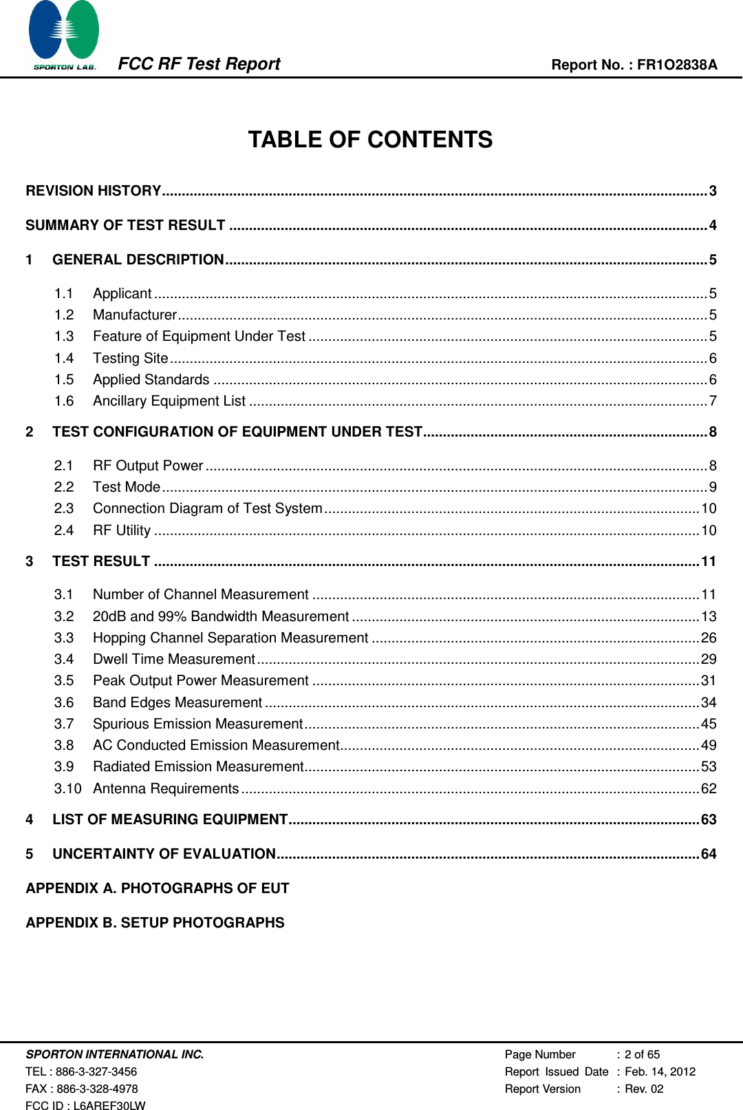
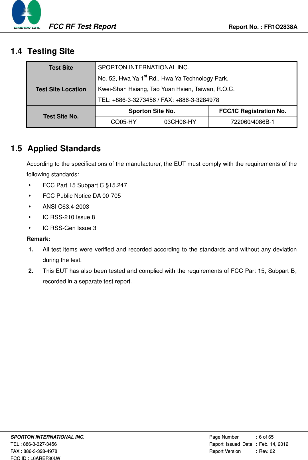
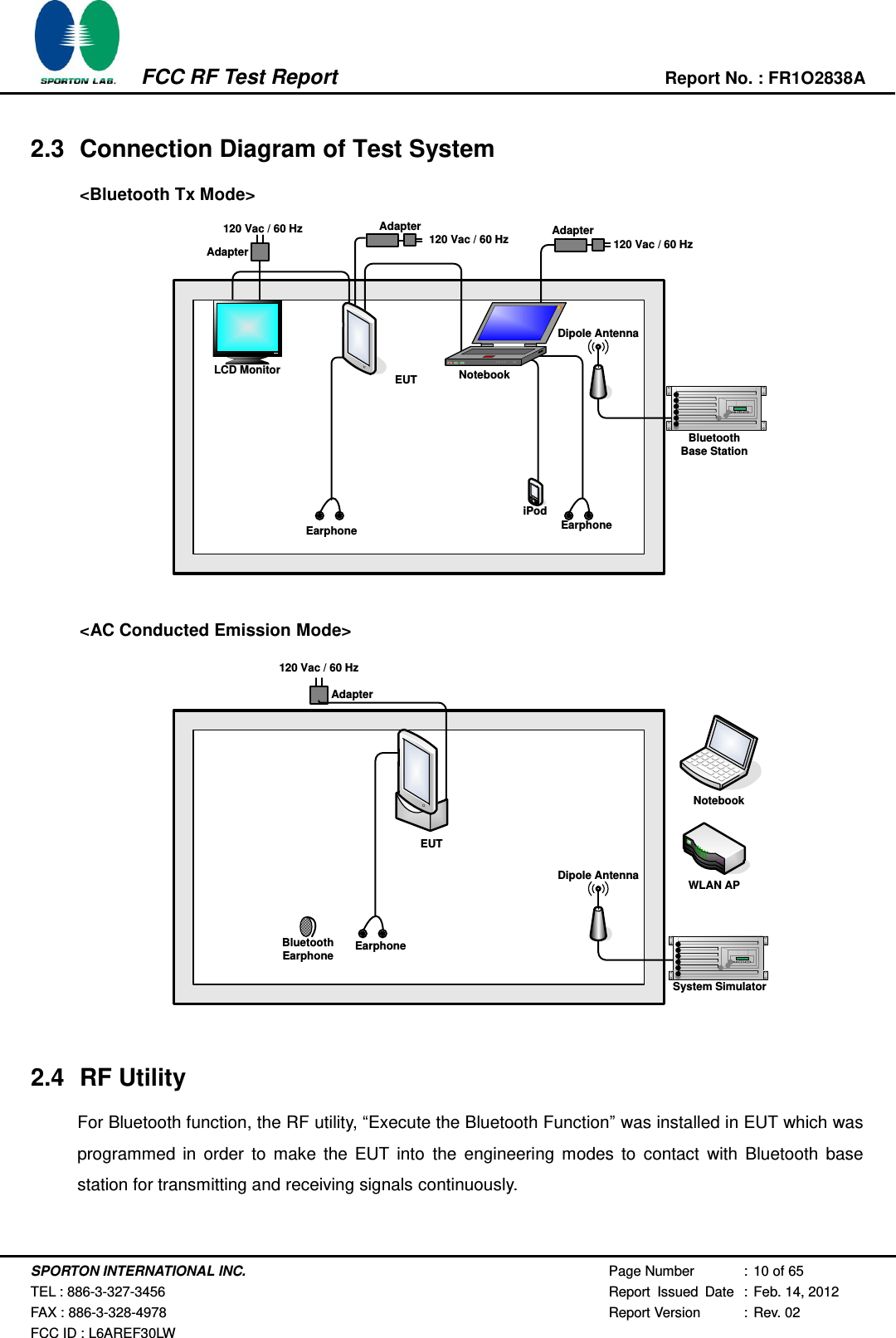
![SPORTON INTERNATIONAL INC. Page Number : 14 of 65 TEL : 886-3-327-3456 Report Issued Date : Feb. 14, 2012 FAX : 886-3-328-4978 Report Version : Rev. 02 FCC ID : L6AREF30LW FCC RF Test Report Report No. : FR1O2838A 3.2.5 Test Result of 20dB Bandwidth Test Mode : Mode 1, 2, 3 Temperature : 22~24℃ Test Engineer : Reece Li Relative Humidity : 53~57% Channel Frequency (MHz) 20dB Bandwidth (MHz) 00 2402 0.904 39 2441 0.904 78 2480 0.904 20 dB Bandwidth Plot on Channel 00 Ref 20 dBmAtt 20 dB***Offset 20.2 dB 1 PKMAXH A LVL3DBRBW 30 kHzVBW 300 kHzSWT 2.5 msCenter2.402 GHzSpan2 MHz200 kHz/-80-70-60-50-40-30-20-10010201Marker 1 [T1 ] 5.37 dBm 2.401984000 GHzndB [T1] 20.00 dB BW 904.000000000 kHzT1Temp 1 [T1 ndB] -14.24 dBm 2.401548000 GHzT2Temp 2 [T1 ndB] -14.91 dBm 2.402452000 GHzDate: 29.NOV.2011 20:42:43720510](https://usermanual.wiki/BlackBerry/REF30LW.DSS-test-report/User-Guide-1699527-Page-14.png)
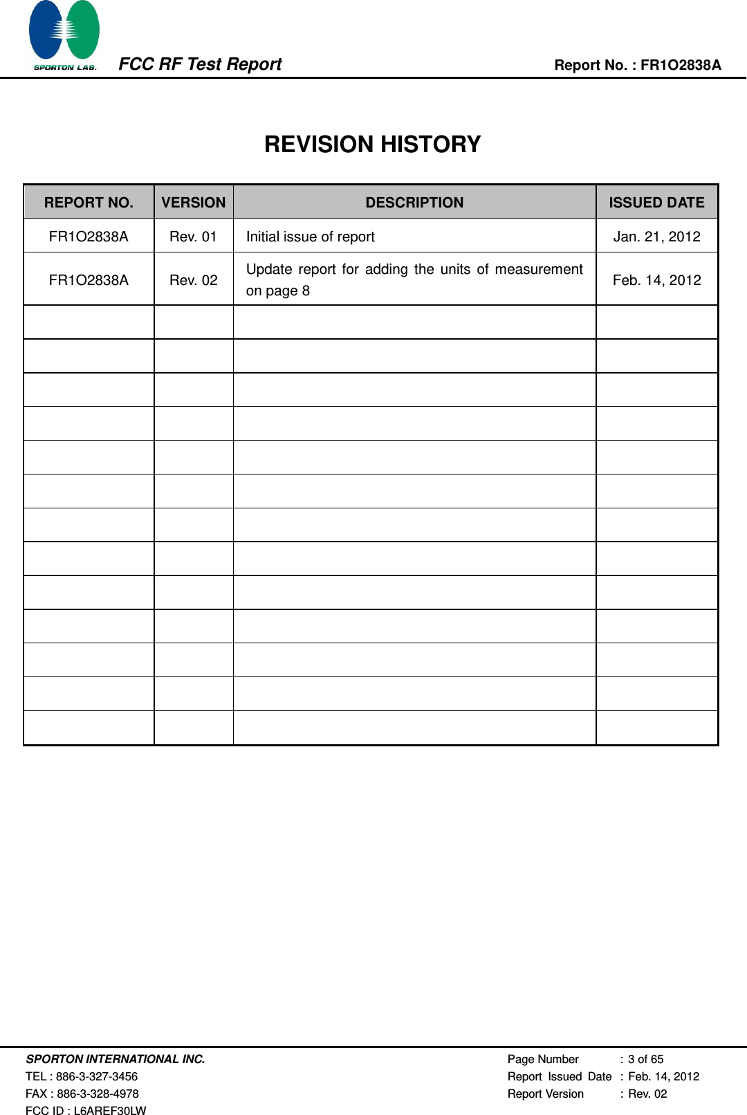
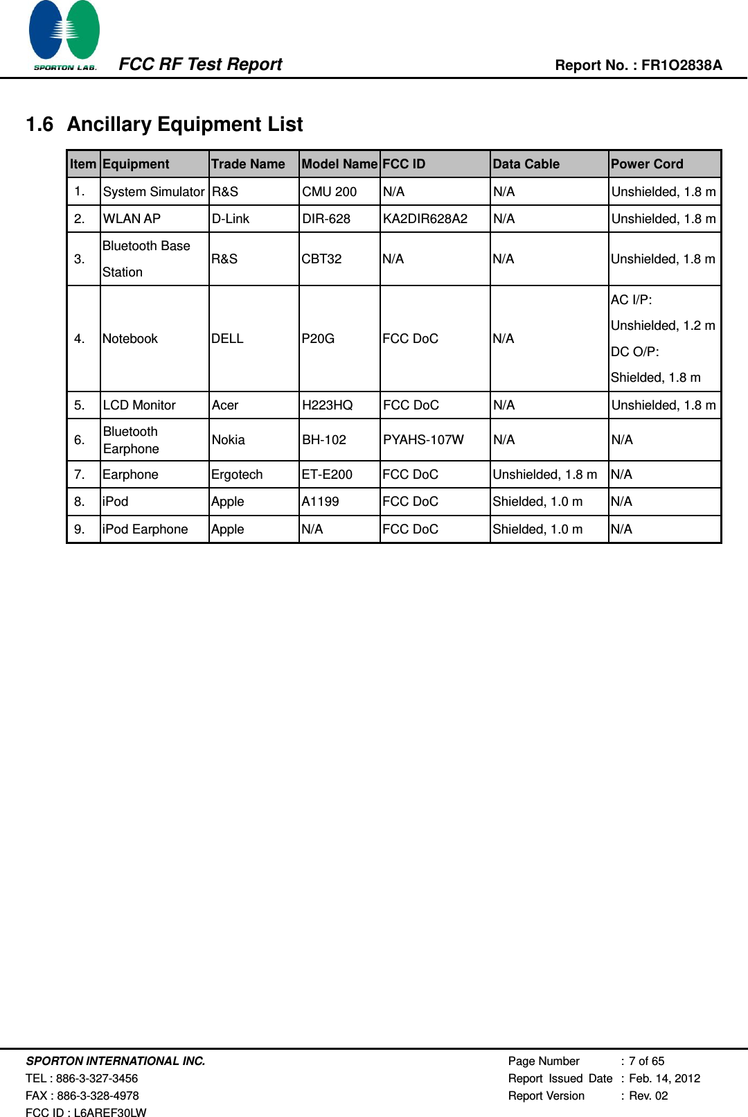
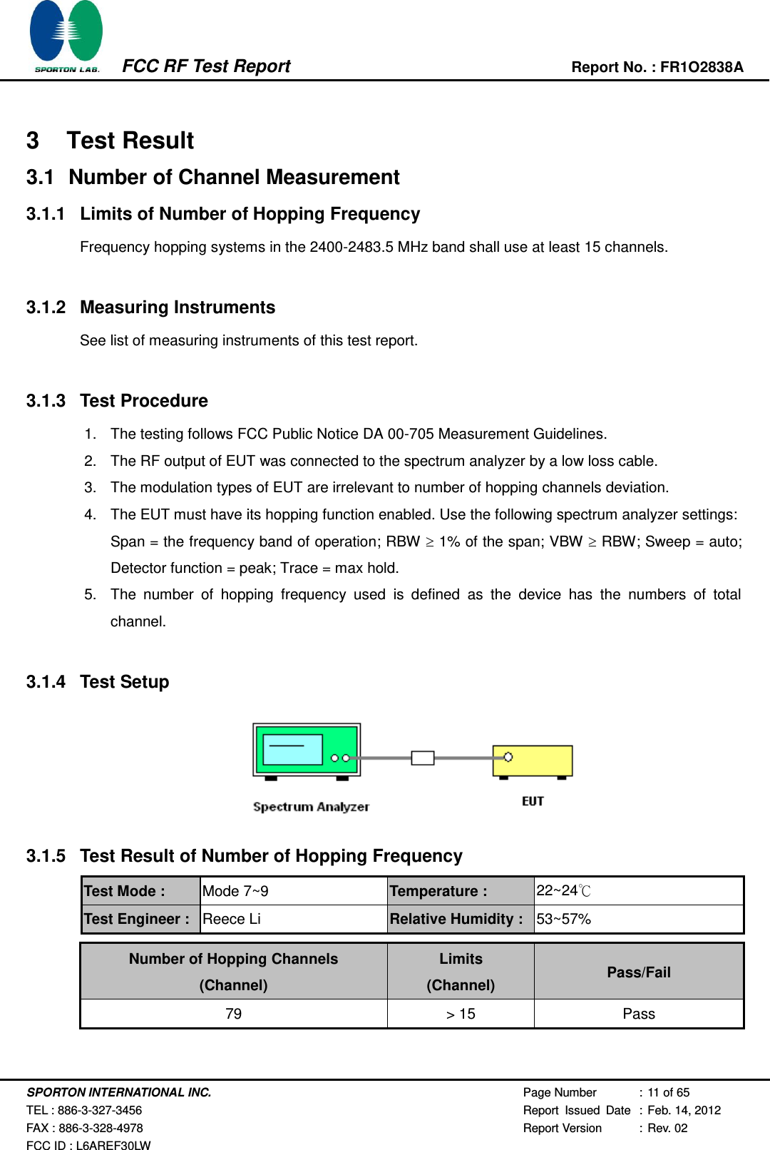
![SPORTON INTERNATIONAL INC. Page Number : 15 of 65 TEL : 886-3-327-3456 Report Issued Date : Feb. 14, 2012 FAX : 886-3-328-4978 Report Version : Rev. 02 FCC ID : L6AREF30LW FCC RF Test Report Report No. : FR1O2838A 20 dB Bandwidth Plot on Channel 39 20 dB Bandwidth Plot on Channel 78 Ref 20 dBmAtt 20 dB***Offset 20.2 dB 1 PKMAXH A LVL3DBRBW 30 kHzVBW 300 kHzSWT 2.5 msCenter2.441 GHzSpan2 MHz200 kHz/-80-70-60-50-40-30-20-10010201Marker 1 [T1 ] 5.61 dBm 2.440984000 GHzndB [T1] 20.00 dB BW 904.000000000 kHzT1Temp 1 [T1 ndB] -14.54 dBm 2.440544000 GHzT2Temp 2 [T1 ndB] -13.86 dBm 2.441448000 GHzDate: 29.NOV.2011 20:43:53Ref 20 dBmAtt 20 dB***Offset 20.2 dB 1 PKMAXH A LVL3DBRBW 30 kHzVBW 300 kHzSWT 2.5 msCenter2.48 GHzSpan2 MHz200 kHz/-80-70-60-50-40-30-20-10010201Marker 1 [T1 ] 5.41 dBm 2.479984000 GHzndB [T1] 20.00 dB BW 904.000000000 kHzT1Temp 1 [T1 ndB] -13.90 dBm 2.479548000 GHzT2Temp 2 [T1 ndB] -14.77 dBm 2.480452000 GHzDate: 29.NOV.2011 20:45:00720510 720510](https://usermanual.wiki/BlackBerry/REF30LW.DSS-test-report/User-Guide-1699527-Page-15.png)
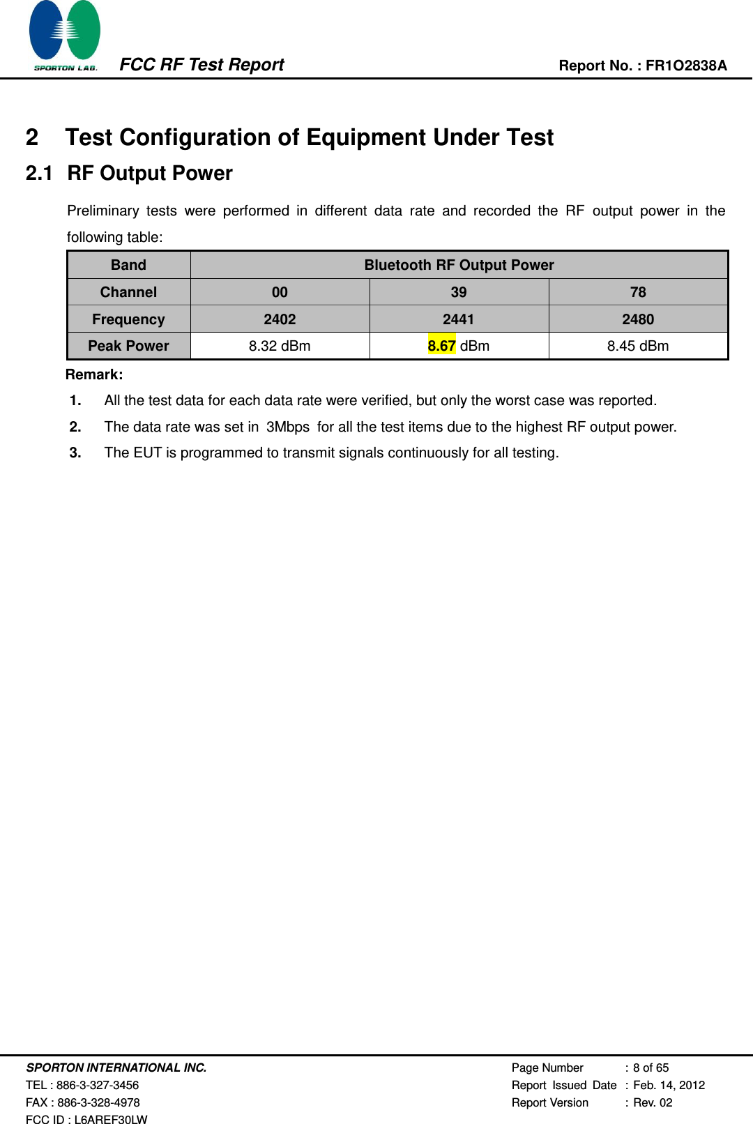
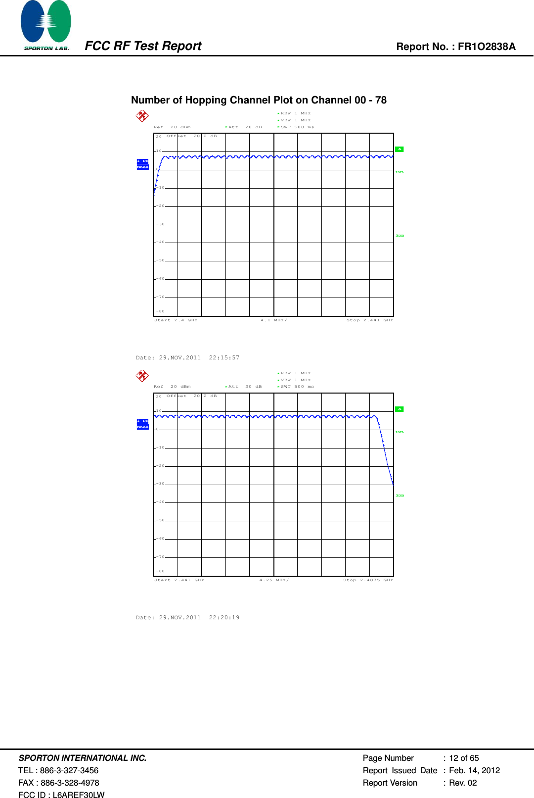
![SPORTON INTERNATIONAL INC. Page Number : 16 of 65 TEL : 886-3-327-3456 Report Issued Date : Feb. 14, 2012 FAX : 886-3-328-4978 Report Version : Rev. 02 FCC ID : L6AREF30LW FCC RF Test Report Report No. : FR1O2838A Test Mode : Mode 4, 5, 6 Temperature : 22~24℃ Test Engineer : Reece Li Relative Humidity : 53~57% Channel Frequency (MHz) 20dB Bandwidth (MHz) 00 2402 1.344 39 2441 1.350 78 2480 1.344 20 dB Bandwidth Plot on Channel 00 Ref 20 dBmAtt 20 dB***Offset 20.2 dB 1 PKMAXH A LVL3DBRBW 30 kHzVBW 300 kHzSWT 5 msCenter2.402 GHzSpan3 MHz300 kHz/-80-70-60-50-40-30-20-10010201Marker 1 [T1 ] 2.85 dBm 2.401988000 GHzndB [T1] 20.00 dB BW 1.344000000 MHzT1Temp 1 [T1 ndB] -17.05 dBm 2.401328000 GHzT2Temp 2 [T1 ndB] -17.45 dBm 2.402672000 GHzDate: 29.NOV.2011 20:46:04720510](https://usermanual.wiki/BlackBerry/REF30LW.DSS-test-report/User-Guide-1699527-Page-16.png)
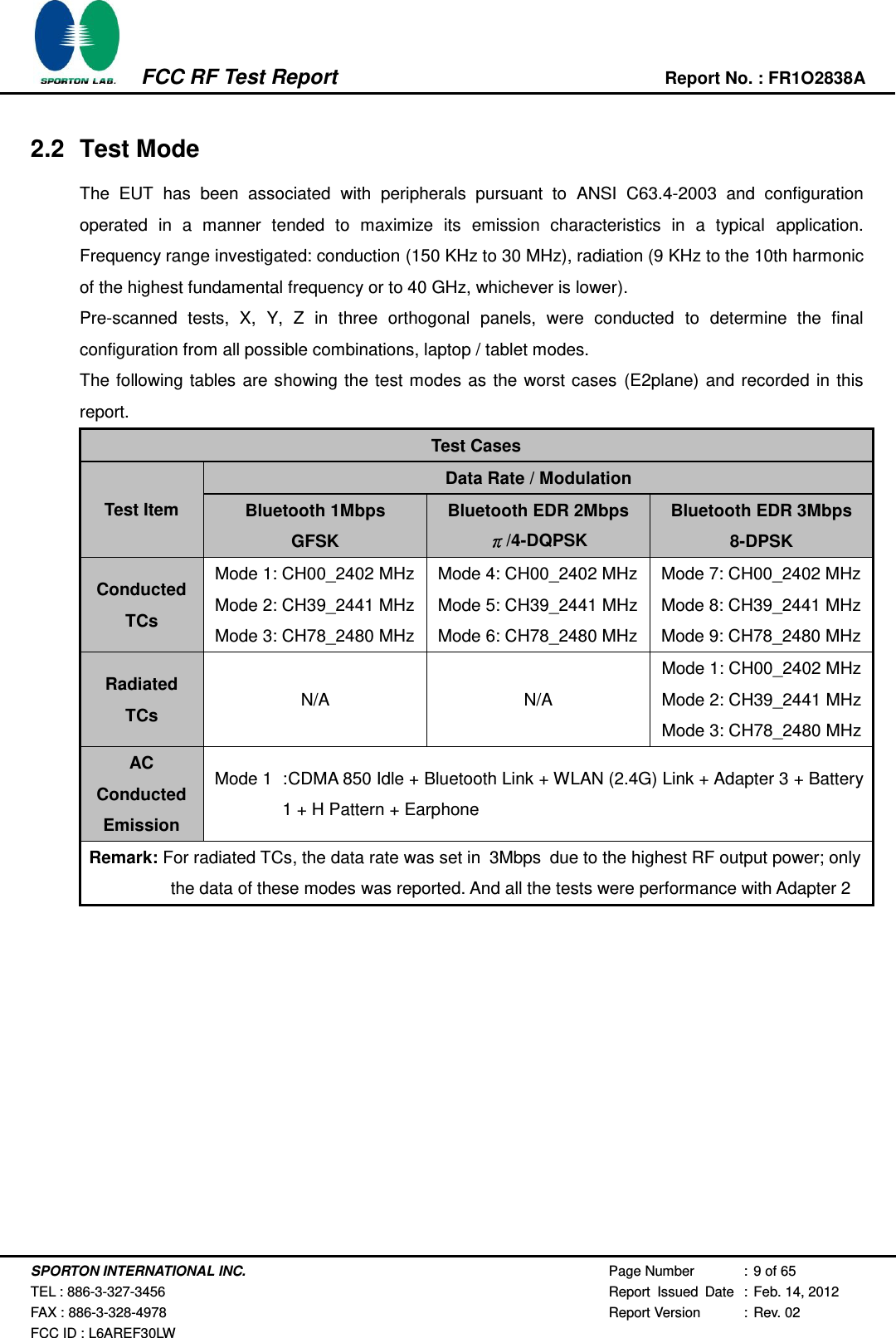
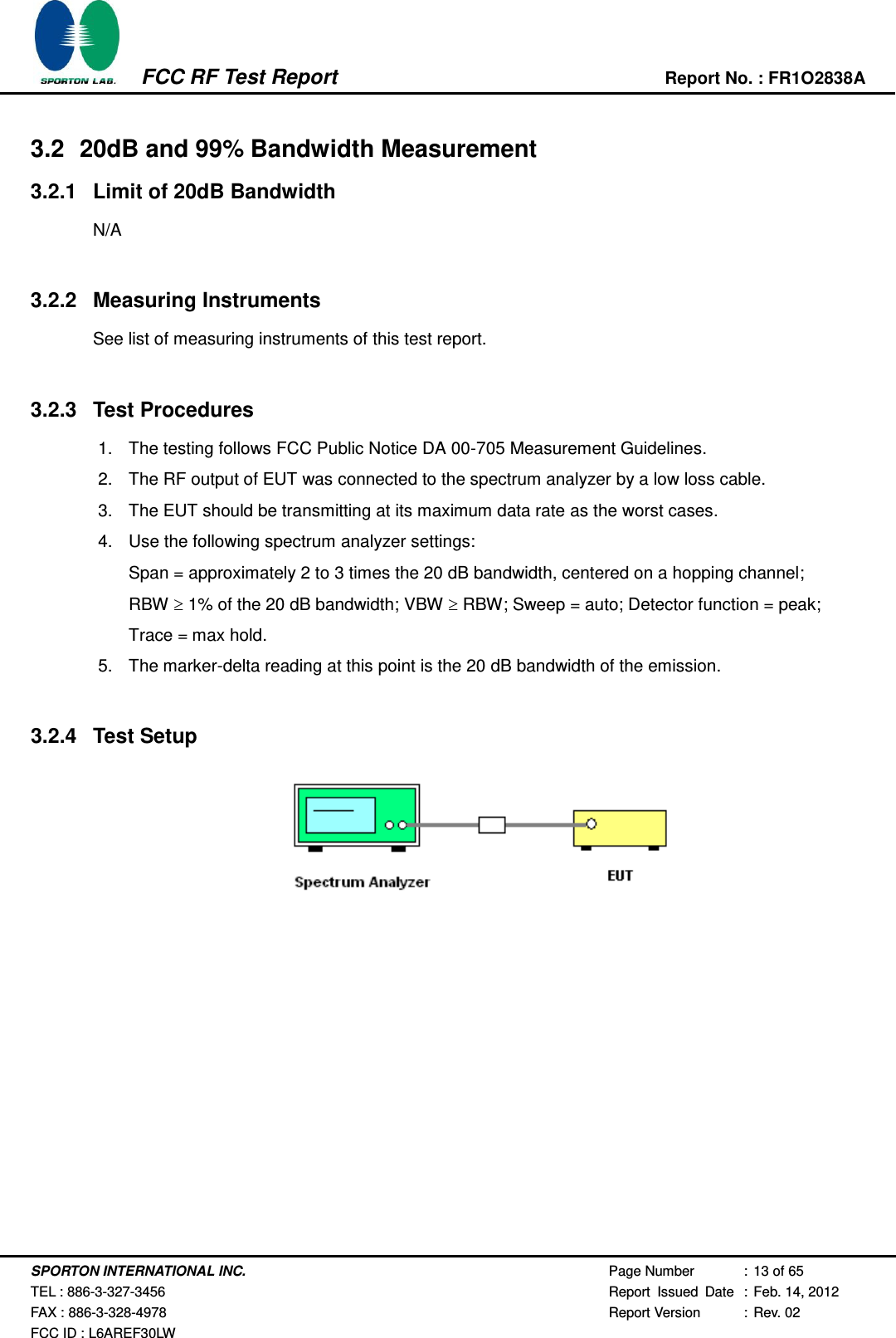
![SPORTON INTERNATIONAL INC. Page Number : 17 of 65 TEL : 886-3-327-3456 Report Issued Date : Feb. 14, 2012 FAX : 886-3-328-4978 Report Version : Rev. 02 FCC ID : L6AREF30LW FCC RF Test Report Report No. : FR1O2838A 20 dB Bandwidth Plot on Channel 39 20 dB Bandwidth Plot on Channel 78 Ref 20 dBmAtt 20 dB***Offset 20.2 dB 1 PKMAXH A LVL3DBRBW 30 kHzVBW 300 kHzSWT 5 msCenter2.441 GHzSpan3 MHz300 kHz/-80-70-60-50-40-30-20-10010201Marker 1 [T1 ] 3.18 dBm 2.440988000 GHzndB [T1] 20.00 dB BW 1.350000000 MHzT1Temp 1 [T1 ndB] -17.16 dBm 2.440322000 GHzT2Temp 2 [T1 ndB] -17.13 dBm 2.441672000 GHzDate: 29.NOV.2011 20:46:45Ref 20 dBmAtt 20 dB***Offset 20.2 dB 1 PKMAXH A LVL3DBRBW 30 kHzVBW 300 kHzSWT 5 msCenter2.48 GHzSpan3 MHz300 kHz/-80-70-60-50-40-30-20-10010201Marker 1 [T1 ] 3.03 dBm 2.479988000 GHzndB [T1] 20.00 dB BW 1.344000000 MHzT1Temp 1 [T1 ndB] -16.71 dBm 2.479328000 GHzT2Temp 2 [T1 ndB] -17.04 dBm 2.480672000 GHzDate: 29.NOV.2011 20:47:49720510 720510](https://usermanual.wiki/BlackBerry/REF30LW.DSS-test-report/User-Guide-1699527-Page-17.png)
![SPORTON INTERNATIONAL INC. Page Number : 18 of 65 TEL : 886-3-327-3456 Report Issued Date : Feb. 14, 2012 FAX : 886-3-328-4978 Report Version : Rev. 02 FCC ID : L6AREF30LW FCC RF Test Report Report No. : FR1O2838A Test Mode : Mode 7, 8, 9 Temperature : 22~24℃ Test Engineer : Reece Li Relative Humidity : 53~57% Channel Frequency (MHz) 20dB Bandwidth (MHz) 00 2402 1.284 39 2441 1.284 78 2480 1.302 20 dB Bandwidth Plot on Channel 00 A Offset 20.2 dBLVLRef 20 dBmCenter2.402 GHzSpan3 MHz300 kHz/Att 20 dB*3DBRBW 30 kHzSWT 5 ms*VBW 300 kHz* 1 PKMAXH-80-70-60-50-40-30-20-10010201Marker 1 [T1 ] 2.85 dBm 2.401988000 GHzndB [T1] 20.00 dB BW 1.284000000 MHzT1Temp 1 [T1 ndB] -16.74 dBm 2.401358000 GHzT2Temp 2 [T1 ndB] -17.19 dBm 2.402642000 GHzDate: 29.NOV.2011 21:39:22720510](https://usermanual.wiki/BlackBerry/REF30LW.DSS-test-report/User-Guide-1699527-Page-18.png)
![SPORTON INTERNATIONAL INC. Page Number : 19 of 65 TEL : 886-3-327-3456 Report Issued Date : Feb. 14, 2012 FAX : 886-3-328-4978 Report Version : Rev. 02 FCC ID : L6AREF30LW FCC RF Test Report Report No. : FR1O2838A 20 dB Bandwidth Plot on Channel 39 20 dB Bandwidth Plot on Channel 78 A Offset 20.2 dBLVLRef 20 dBmCenter2.441 GHzSpan3 MHz300 kHz/Att 20 dB*3DBRBW 30 kHzSWT 5 ms*VBW 300 kHz* 1 PKMAXH-80-70-60-50-40-30-20-10010201Marker 1 [T1 ] 3.38 dBm 2.440988000 GHzndB [T1] 20.00 dB BW 1.284000000 MHzT1Temp 1 [T1 ndB] -16.84 dBm 2.440358000 GHzT2Temp 2 [T1 ndB] -16.37 dBm 2.441642000 GHzDate: 29.NOV.2011 21:39:50 A Offset 20.2 dBLVLRef 20 dBmCenter2.48 GHzSpan3 MHz300 kHz/Att 20 dB*3DBRBW 30 kHzSWT 5 ms*VBW 300 kHz* 1 PKMAXH-80-70-60-50-40-30-20-10010201Marker 1 [T1 ] 3.11 dBm 2.479982000 GHzndB [T1] 20.00 dB BW 1.302000000 MHzT1Temp 1 [T1 ndB] -16.84 dBm 2.479358000 GHzT2Temp 2 [T1 ndB] -17.15 dBm 2.480660000 GHzDate: 29.NOV.2011 21:38:53720510 720510](https://usermanual.wiki/BlackBerry/REF30LW.DSS-test-report/User-Guide-1699527-Page-19.png)
![SPORTON INTERNATIONAL INC. Page Number : 20 of 65 TEL : 886-3-327-3456 Report Issued Date : Feb. 14, 2012 FAX : 886-3-328-4978 Report Version : Rev. 02 FCC ID : L6AREF30LW FCC RF Test Report Report No. : FR1O2838A 3.2.6 Test Result of 99% Occupied Bandwidth Test Mode : Mode 1, 2, 3 Temperature : 22~24℃ Test Engineer : Reece Li Relative Humidity : 53~57% Channel Frequency (MHz) 99% Occupied Bandwidth (MHz) 00 2402 0.828 39 2441 0.832 78 2480 0.836 99% Bandwidth Plot on Channel 00 A Offset 20.2 dBLVLRef 20 dBmCenter2.402 GHzSpan2 MHz200 kHz/Att 20 dB***3DBRBW 30 kHzVBW 30 kHzSWT 5 ms* 1 SAMAXH-80-70-60-50-40-30-20-10010201Marker 1 [T1 ] 4.47 dBm 2.401988000 GHzOBW828.000000000 kHzT1Temp 1 [T1 OBW] -13.99 dBm 2.401588000 GHzT2Temp 2 [T1 OBW] -14.33 dBm 2.402416000 GHzDate: 29.NOV.2011 22:07:48720510](https://usermanual.wiki/BlackBerry/REF30LW.DSS-test-report/User-Guide-1699527-Page-20.png)
![SPORTON INTERNATIONAL INC. Page Number : 21 of 65 TEL : 886-3-327-3456 Report Issued Date : Feb. 14, 2012 FAX : 886-3-328-4978 Report Version : Rev. 02 FCC ID : L6AREF30LW FCC RF Test Report Report No. : FR1O2838A 99% Occupied Bandwidth Plot on Channel 39 99% Occupied Bandwidth Plot on Channel 78 A Offset 20.2 dBLVLRef 20 dBmCenter2.441 GHzSpan2 MHz200 kHz/Att 20 dB***3DBRBW 30 kHzVBW 30 kHzSWT 5 ms* 1 SAMAXH-80-70-60-50-40-30-20-10010201Marker 1 [T1 ] 4.94 dBm 2.440988000 GHzOBW832.000000000 kHzT1Temp 1 [T1 OBW] -13.53 dBm 2.440584000 GHzT2Temp 2 [T1 OBW] -13.93 dBm 2.441416000 GHzDate: 29.NOV.2011 22:08:27 A Offset 20.2 dBLVLRef 20 dBmCenter2.48 GHzSpan2 MHz200 kHz/Att 20 dB***3DBRBW 30 kHzVBW 30 kHzSWT 5 ms* 1 SAMAXH-80-70-60-50-40-30-20-10010201Marker 1 [T1 ] 4.76 dBm 2.479984000 GHzOBW836.000000000 kHzT1Temp 1 [T1 OBW] -13.77 dBm 2.479584000 GHzT2Temp 2 [T1 OBW] -13.47 dBm 2.480420000 GHzDate: 29.NOV.2011 22:07:12720510 720510](https://usermanual.wiki/BlackBerry/REF30LW.DSS-test-report/User-Guide-1699527-Page-21.png)
![SPORTON INTERNATIONAL INC. Page Number : 22 of 65 TEL : 886-3-327-3456 Report Issued Date : Feb. 14, 2012 FAX : 886-3-328-4978 Report Version : Rev. 02 FCC ID : L6AREF30LW FCC RF Test Report Report No. : FR1O2838A Test Mode : Mode 4, 5, 6 Temperature : 22~24℃ Test Engineer : Reece Li Relative Humidity : 53~57% Channel Frequency (MHz) 99% Occupied Bandwidth (MHz) 00 2402 1.196 39 2441 1.196 78 2480 1.196 99% Bandwidth Plot on Channel 00 A Offset 20.2 dBLVLRef 20 dBmCenter2.402 GHzSpan2 MHz200 kHz/Att 20 dB***3DBRBW 30 kHzVBW 30 kHzSWT 5 ms* 1 SAMAXH-80-70-60-50-40-30-20-10010201Marker 1 [T1 ] 2.09 dBm 2.401984000 GHzOBW 1.196000000 MHzT1Temp 1 [T1 OBW] -12.26 dBm 2.401400000 GHzT2Temp 2 [T1 OBW] -13.45 dBm 2.402596000 GHzDate: 29.NOV.2011 22:04:56720510](https://usermanual.wiki/BlackBerry/REF30LW.DSS-test-report/User-Guide-1699527-Page-22.png)
![SPORTON INTERNATIONAL INC. Page Number : 23 of 65 TEL : 886-3-327-3456 Report Issued Date : Feb. 14, 2012 FAX : 886-3-328-4978 Report Version : Rev. 02 FCC ID : L6AREF30LW FCC RF Test Report Report No. : FR1O2838A 99% Occupied Bandwidth Plot on Channel 39 99% Occupied Bandwidth Plot on Channel 78 A Offset 20.2 dBLVLRef 20 dBmCenter2.441 GHzSpan2 MHz200 kHz/Att 20 dB***3DBRBW 30 kHzVBW 30 kHzSWT 5 ms* 1 SAMAXH-80-70-60-50-40-30-20-10010201Marker 1 [T1 ] 2.78 dBm 2.440984000 GHzOBW 1.196000000 MHzT1Temp 1 [T1 OBW] -11.52 dBm 2.440400000 GHzT2Temp 2 [T1 OBW] -12.81 dBm 2.441596000 GHzDate: 29.NOV.2011 22:03:06 A Offset 20.2 dBLVLRef 20 dBmCenter2.48 GHzSpan2 MHz200 kHz/Att 20 dB***3DBRBW 30 kHzVBW 30 kHzSWT 5 ms* 1 SAMAXH-80-70-60-50-40-30-20-10010201Marker 1 [T1 ] 2.45 dBm 2.479988000 GHzOBW 1.196000000 MHzT1Temp 1 [T1 OBW] -11.65 dBm 2.479400000 GHzT2Temp 2 [T1 OBW] -13.01 dBm 2.480596000 GHzDate: 29.NOV.2011 22:05:38720510 720510](https://usermanual.wiki/BlackBerry/REF30LW.DSS-test-report/User-Guide-1699527-Page-23.png)
![SPORTON INTERNATIONAL INC. Page Number : 24 of 65 TEL : 886-3-327-3456 Report Issued Date : Feb. 14, 2012 FAX : 886-3-328-4978 Report Version : Rev. 02 FCC ID : L6AREF30LW FCC RF Test Report Report No. : FR1O2838A Test Mode : Mode 7, 8, 9 Temperature : 22~24℃ Test Engineer : Reece Li Relative Humidity : 53~57% Channel Frequency (MHz) 99% Occupied Bandwidth (MHz) 00 2402 1.172 39 2441 1.172 78 2480 1.172 99% Bandwidth Plot on Channel 00 A Offset 20.2 dBLVLRef 20 dBmCenter2.402 GHzSpan2 MHz200 kHz/Att 20 dB***3DBRBW 30 kHzVBW 30 kHzSWT 5 ms* 1 SAMAXH-80-70-60-50-40-30-20-10010201Marker 1 [T1 ] 2.33 dBm 2.401984000 GHzOBW 1.172000000 MHzT1Temp 1 [T1 OBW] -12.60 dBm 2.401420000 GHzT2Temp 2 [T1 OBW] -11.87 dBm 2.402592000 GHzDate: 29.NOV.2011 21:59:49720510](https://usermanual.wiki/BlackBerry/REF30LW.DSS-test-report/User-Guide-1699527-Page-24.png)
![SPORTON INTERNATIONAL INC. Page Number : 25 of 65 TEL : 886-3-327-3456 Report Issued Date : Feb. 14, 2012 FAX : 886-3-328-4978 Report Version : Rev. 02 FCC ID : L6AREF30LW FCC RF Test Report Report No. : FR1O2838A 99% Occupied Bandwidth Plot on Channel 39 99% Occupied Bandwidth Plot on Channel 78 A Offset 20.2 dBLVLRef 20 dBmCenter2.441 GHzSpan2 MHz200 kHz/Att 20 dB***3DBRBW 30 kHzVBW 30 kHzSWT 5 ms* 1 SAMAXH-80-70-60-50-40-30-20-10010201Marker 1 [T1 ] 2.80 dBm 2.440984000 GHzOBW 1.172000000 MHzT1Temp 1 [T1 OBW] -12.26 dBm 2.440420000 GHzT2Temp 2 [T1 OBW] -11.19 dBm 2.441592000 GHzDate: 29.NOV.2011 22:00:26 A Offset 20.2 dBLVLRef 20 dBmCenter2.48 GHzSpan2 MHz200 kHz/Att 20 dB***3DBRBW 30 kHzVBW 30 kHzSWT 5 ms* 1 SAMAXH-80-70-60-50-40-30-20-10010201Marker 1 [T1 ] 2.60 dBm 2.479984000 GHzOBW 1.172000000 MHzT1Temp 1 [T1 OBW] -12.36 dBm 2.479420000 GHzT2Temp 2 [T1 OBW] -11.17 dBm 2.480592000 GHzDate: 29.NOV.2011 21:59:08720510 720510](https://usermanual.wiki/BlackBerry/REF30LW.DSS-test-report/User-Guide-1699527-Page-25.png)

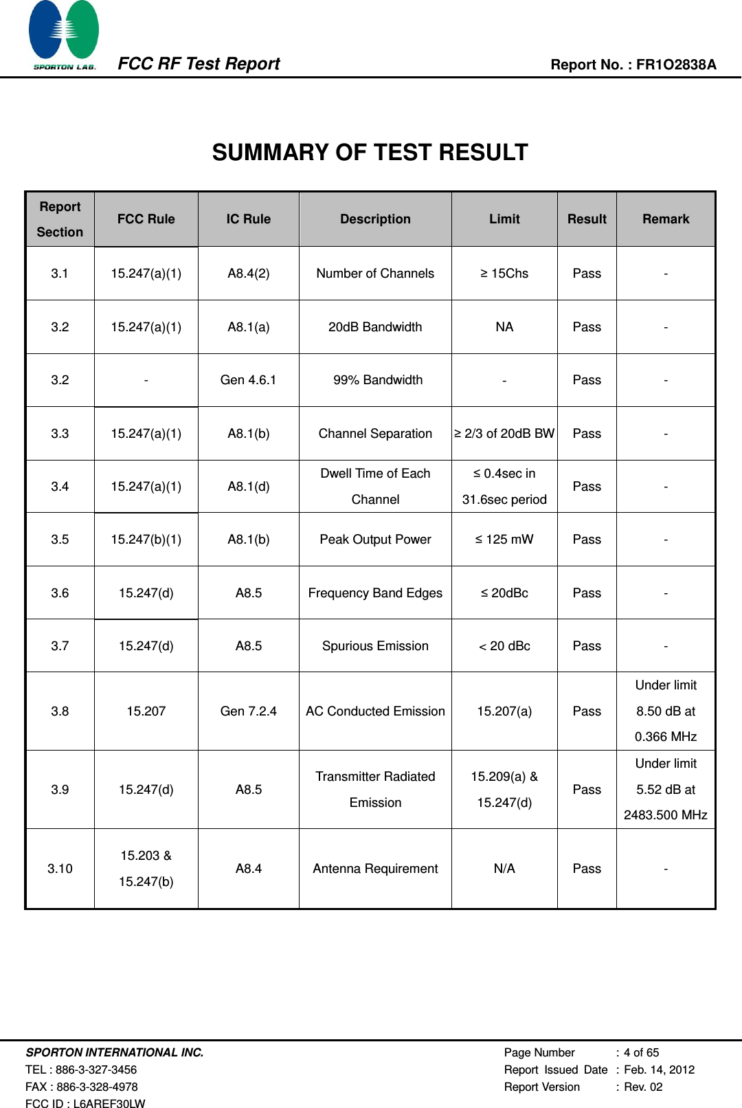
![SPORTON INTERNATIONAL INC. Page Number : 27 of 65 TEL : 886-3-327-3456 Report Issued Date : Feb. 14, 2012 FAX : 886-3-328-4978 Report Version : Rev. 02 FCC ID : L6AREF30LW FCC RF Test Report Report No. : FR1O2838A 3.3.5 Test Result of Hopping Channel Separation Test Mode : Mode 7, 8, 9 Temperature : 22~24℃ Test Engineer : Reece Li Relative Humidity : 53~57% Channel Frequency (MHz) Frequency Separation (MHz) (2/3 of 20dB BW) Limits (MHz) Pass/Fail 00 2402 1.002 0.8560 Pass 39 2441 1.002 0.8560 Pass 78 2480 1.002 0.8680 Pass Channel Separation Plot on Channel 00 - 01 A Offset 20.2 dBLVLRef 20 dBmCenter2.4025 GHzSpan3 MHz300 kHz/Att 20 dB*3DBRBW 30 kHzSWT 5 ms*VBW 100 kHz* 1 PKMAXH-80-70-60-50-40-30-20-10010201Marker 1 [T1 ] 2.80 dBm 2.401990000 GHz2Delta 2 [T1 ] 0.12 dB 1.002000000 MHzDate: 29.NOV.2011 21:17:48720510](https://usermanual.wiki/BlackBerry/REF30LW.DSS-test-report/User-Guide-1699527-Page-27.png)
![SPORTON INTERNATIONAL INC. Page Number : 28 of 65 TEL : 886-3-327-3456 Report Issued Date : Feb. 14, 2012 FAX : 886-3-328-4978 Report Version : Rev. 02 FCC ID : L6AREF30LW FCC RF Test Report Report No. : FR1O2838A Channel Separation Plot on Channel 39 - 40 Channel Separation Plot on Channel 77 - 78 A Offset 20.2 dBLVLRef 20 dBmCenter2.4415 GHzSpan3 MHz300 kHz/Att 20 dB*3DBRBW 30 kHzSWT 5 ms*VBW 100 kHz* 1 PKMAXH-80-70-60-50-40-30-20-10010201Marker 1 [T1 ] 3.37 dBm 2.440984000 GHz2Delta 2 [T1 ] 0.04 dB 1.002000000 MHzDate: 29.NOV.2011 21:18:49Ref 20 dBmAtt 20 dB***Offset 20.2 dB 1 PKMAXH A LVL3DBRBW 30 kHzVBW 100 kHzSWT 5 msCenter2.4795 GHzSpan3 MHz300 kHz/-80-70-60-50-40-30-20-10010201Marker 1 [T1 ] 3.14 dBm 2.478984000 GHz2Delta 2 [T1 ] 0.06 dB 1.002000000 MHzDate: 29.NOV.2011 21:24:54720510 720510](https://usermanual.wiki/BlackBerry/REF30LW.DSS-test-report/User-Guide-1699527-Page-28.png)
![SPORTON INTERNATIONAL INC. Page Number : 30 of 65 TEL : 886-3-327-3456 Report Issued Date : Feb. 14, 2012 FAX : 886-3-328-4978 Report Version : Rev. 02 FCC ID : L6AREF30LW FCC RF Test Report Report No. : FR1O2838A 3DH5 Dwell Time (One Pulse) Plot on Channel 39 3DH5 Dwell Time (Count Pulses) Plot on Channel 39 Ref 20 dBmAtt 20 dB**Offset 20.2 dBCenter 2.441 GHz1 ms/ 1 PKMAXH A SGLLVL3DBRBW 1 MHzVBW 1 MHzSWT 10 ms-80-70-60-50-40-30-20-10010201Marker 1 [T1 ] -49.28 dBm 2.200000 ms 2Delta 2 [T1 ] 0.94 dB 2.980000 ms 3Delta 3 [T1 ] 0.89 dB 3.740000 ms Date: 29.NOV.2011 21:11:59 A Offset 20.2 dBLVLRef 20 dBmAtt 20 dB*3DBRBW 1 MHzVBW 1 MHz*Center 2.441 GHz1 s/SWT 10 s1 PKMAXHSGL -80-70-60-50-40-30-20-1001020Date: 29.NOV.2011 21:10:01720510 720510](https://usermanual.wiki/BlackBerry/REF30LW.DSS-test-report/User-Guide-1699527-Page-30.png)
![SPORTON INTERNATIONAL INC. Page Number : 32 of 65 TEL : 886-3-327-3456 Report Issued Date : Feb. 14, 2012 FAX : 886-3-328-4978 Report Version : Rev. 02 FCC ID : L6AREF30LW FCC RF Test Report Report No. : FR1O2838A Peak Output Power Plot on Channel 00 Peak Output Power Plot on Channel 39 A Att 20 dB**Ref 20 dBmOffset 20.2 dBLVLCenter2.402 GHzSpan6 MHz600 kHz/*3DBRBW 3 MHzSWT 500 ms*VBW 3 MHz* 1 PKMAXH-80-70-60-50-40-30-20-10010201Marker 1 [T1 ] 8.32 dBm 2.402000000 GHzDate: 29.NOV.2011 20:30:06 A Att 20 dB**Ref 20 dBmOffset 20.2 dBLVLCenter2.441 GHzSpan6 MHz600 kHz/*3DBRBW 3 MHzSWT 500 ms*VBW 3 MHz* 1 PKMAXH-80-70-60-50-40-30-20-10010201Marker 1 [T1 ] 8.67 dBm 2.441000000 GHzDate: 29.NOV.2011 20:31:20720510 720510](https://usermanual.wiki/BlackBerry/REF30LW.DSS-test-report/User-Guide-1699527-Page-32.png)
![SPORTON INTERNATIONAL INC. Page Number : 33 of 65 TEL : 886-3-327-3456 Report Issued Date : Feb. 14, 2012 FAX : 886-3-328-4978 Report Version : Rev. 02 FCC ID : L6AREF30LW FCC RF Test Report Report No. : FR1O2838A Peak Output Power Plot on Channel 78 A Att 20 dB**Ref 20 dBmOffset 20.2 dBLVLCenter2.48 GHzSpan6 MHz600 kHz/*3DBRBW 3 MHzSWT 500 ms*VBW 3 MHz* 1 PKMAXH-80-70-60-50-40-30-20-10010201Marker 1 [T1 ] 8.45 dBm 2.479988000 GHzDate: 29.NOV.2011 20:32:34720510](https://usermanual.wiki/BlackBerry/REF30LW.DSS-test-report/User-Guide-1699527-Page-33.png)
![SPORTON INTERNATIONAL INC. Page Number : 44 of 65 TEL : 886-3-327-3456 Report Issued Date : Feb. 14, 2012 FAX : 886-3-328-4978 Report Version : Rev. 02 FCC ID : L6AREF30LW FCC RF Test Report Report No. : FR1O2838A 3.6.6 Test Result of Conducted Band Edges Test Mode : Mode 7 and 9 Temperature : 22~24℃ Test Channel : 00 and 78 Relative Humidity : 53~57% Test Engineer : Reece Li Low Band Edge Plot on Channel 00 High Band Edge Plot on Channel 78 A Offset 20.2 dBLVLRef 20 dBmAtt 20 dB*3 MHz/Start2.375 GHzStop2.405 GHz3DBRBW 300 kHzSWT 2.5 ms*VBW 300 kHz* 1 PKMAXH-80-70-60-50-40-30-20-10010201Marker 1 [T1 ] -39.41 dBm 2.399720000 GHzD1 5.33 dBmD2 -14.67 dBmF1Date: 29.NOV.2011 21:57:16 A Offset 20.2 dBLVLRef 20 dBmAtt 20 dB*3 MHz/Start2.475 GHzStop2.505 GHz3DBRBW 300 kHzSWT 2.5 ms*VBW 300 kHz* 1 PKMAXH-80-70-60-50-40-30-20-10010201Marker 1 [T1 ] -44.37 dBm 2.491740000 GHzD1 5.67 dBmD2 -14.33 dBmF1Date: 29.NOV.2011 21:58:20720510 720510](https://usermanual.wiki/BlackBerry/REF30LW.DSS-test-report/User-Guide-1699527-Page-44.png)
![SPORTON INTERNATIONAL INC. Page Number : 46 of 65 TEL : 886-3-327-3456 Report Issued Date : Feb. 14, 2012 FAX : 886-3-328-4978 Report Version : Rev. 02 FCC ID : L6AREF30LW FCC RF Test Report Report No. : FR1O2838A 3.7.5 Test Result Test Mode : Mode 7 Temperature : 22~24℃ Test Channel : 00 Relative Humidity : 53~57% Test Engineer : Reece Li Conducted Spurious Emission Plot between 30MHz ~ 3 GHz Conducted Spurious Emission Plot between 3 GHz ~ 25 GHz A Att 20 dB*Ref 20 dBmOffset 20.2 dBLVLStart30 MHzStop3 GHz297 MHz/**3DBRBW 100 kHzVBW 300 kHzSWT 300 ms 1 PKVIEW-80-70-60-50-40-30-20-10010201Marker 1 [T1 ] -45.31 dBm 2.376300000 GHzD1 -16.12 dBmDate: 29.NOV.2011 22:10:17Ref 20 dBmAtt 20 dB**Offset 20.6 dB A LVLRBW 100 kHzVBW 300 kHzSWT 2.2 s*Start3 GHzStop25 GHz2.2 GHz/3DB 1 PKVIEW-80-70-60-50-40-30-20-10010201Marker 1 [T1 ] -33.43 dBm 21.304000000 GHzD1 -16.12 dBmDate: 29.NOV.2011 22:10:39720510 720510](https://usermanual.wiki/BlackBerry/REF30LW.DSS-test-report/User-Guide-1699527-Page-46.png)
![SPORTON INTERNATIONAL INC. Page Number : 47 of 65 TEL : 886-3-327-3456 Report Issued Date : Feb. 14, 2012 FAX : 886-3-328-4978 Report Version : Rev. 02 FCC ID : L6AREF30LW FCC RF Test Report Report No. : FR1O2838A Test Mode : Mode 8 Temperature : 22~24℃ Test Channel : 39 Relative Humidity : 53~57% Test Engineer : Reece Li Conducted Spurious Emission Plot between 30MHz ~ 3 GHz Conducted Spurious Emission Plot between 3 GHz ~ 25 GHz A Att 20 dB*Ref 20 dBmOffset 20.2 dBLVL297 MHz/Start30 MHzStop3 GHz**3DBRBW 100 kHzVBW 300 kHzSWT 300 ms 1 PKVIEW-80-70-60-50-40-30-20-10010201Marker 1 [T1 ] -45.50 dBm 2.376300000 GHzD1 -15.36 dBmDate: 29.NOV.2011 22:09:24Ref 20 dBmAtt 20 dB**Offset 20.6 dB A LVLRBW 100 kHzVBW 300 kHzSWT 2.2 s*Start3 GHzStop25 GHz2.2 GHz/3DB 1 PKVIEW-80-70-60-50-40-30-20-10010201Marker 1 [T1 ] -33.21 dBm 21.920000000 GHzD1 -15.36 dBmDate: 29.NOV.2011 22:09:46720510 720510](https://usermanual.wiki/BlackBerry/REF30LW.DSS-test-report/User-Guide-1699527-Page-47.png)
![SPORTON INTERNATIONAL INC. Page Number : 48 of 65 TEL : 886-3-327-3456 Report Issued Date : Feb. 14, 2012 FAX : 886-3-328-4978 Report Version : Rev. 02 FCC ID : L6AREF30LW FCC RF Test Report Report No. : FR1O2838A Test Mode : Mode 9 Temperature : 22~24℃ Test Channel : 78 Relative Humidity : 53~57% Test Engineer : Reece Li Conducted Spurious Emission Plot between 30MHz ~ 3 GHz Conducted Spurious Emission Plot between 3 GHz ~ 25 GHz A Att 20 dB*Ref 20 dBmOffset 20.2 dBLVLStart30 MHzStop3 GHz297 MHz/**3DBRBW 100 kHzVBW 300 kHzSWT 300 ms 1 PKVIEW-80-70-60-50-40-30-20-10010201Marker 1 [T1 ] -42.83 dBm 2.376300000 GHzD1 -14.31 dBmDate: 29.NOV.2011 22:11:08Ref 20 dBmAtt 20 dB**Offset 20.6 dB A LVLRBW 100 kHzVBW 300 kHzSWT 2.2 s*Start3 GHzStop25 GHz2.2 GHz/3DB 1 PKVIEW-80-70-60-50-40-30-20-10010201Marker 1 [T1 ] -32.12 dBm 21.876000000 GHzD1 -14.31 dBmDate: 29.NOV.2011 22:11:29720510 720510](https://usermanual.wiki/BlackBerry/REF30LW.DSS-test-report/User-Guide-1699527-Page-48.png)
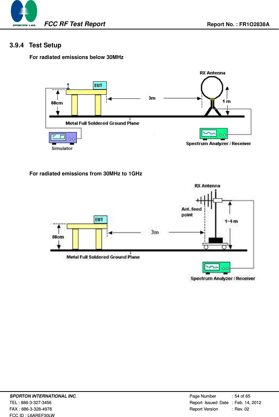
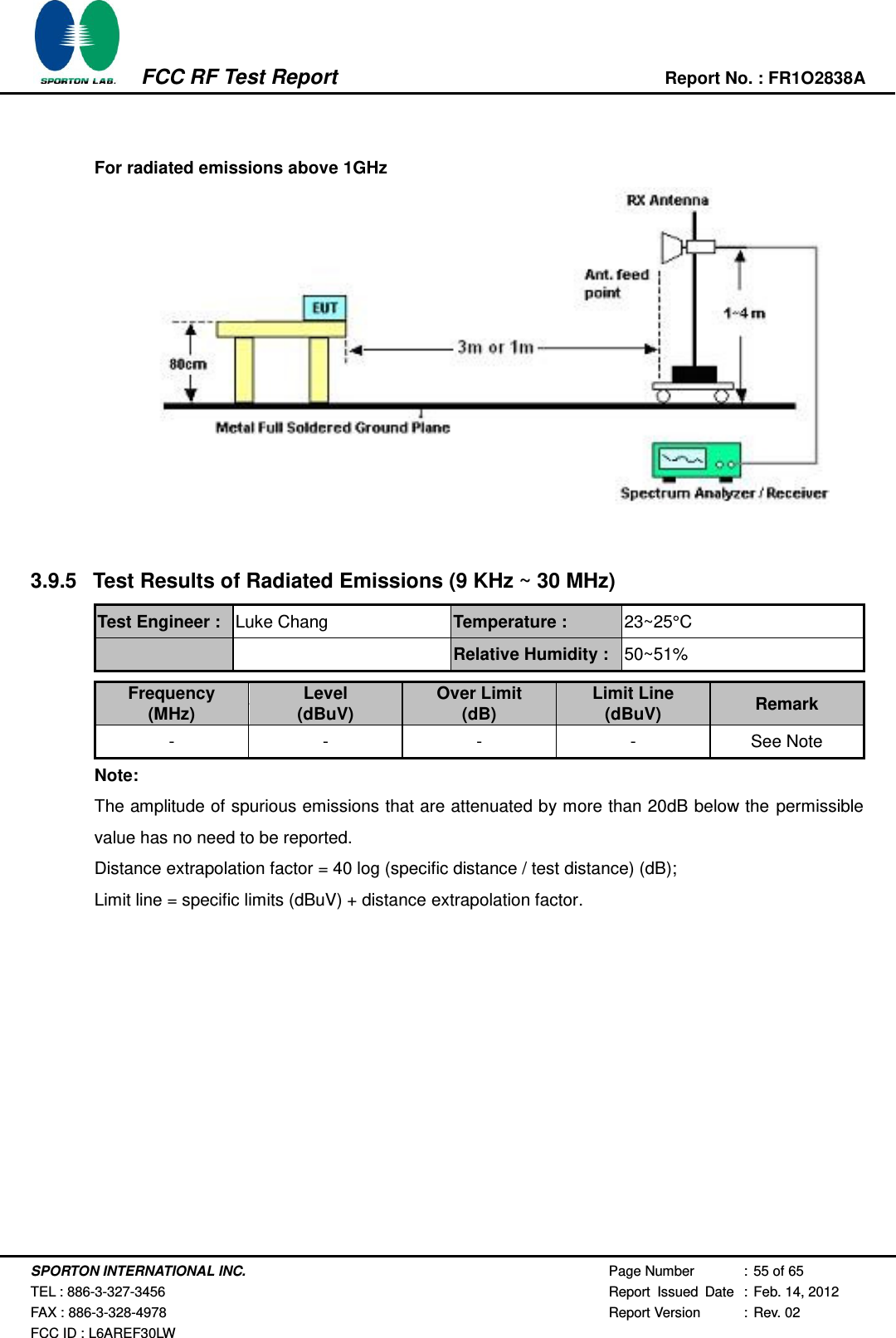
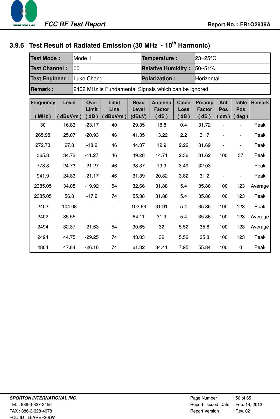
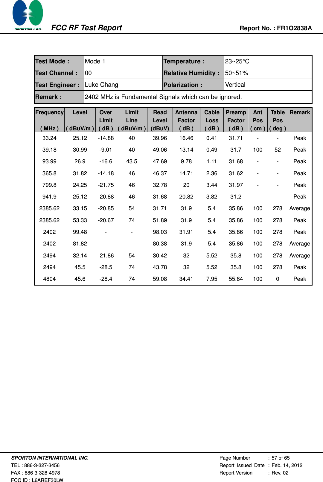
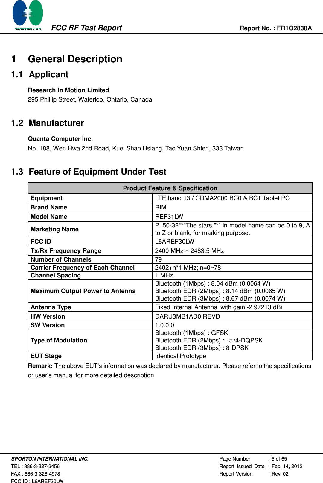
![SPORTON INTERNATIONAL INC. Page Number : 53 of 65 TEL : 886-3-327-3456 Report Issued Date : Feb. 14, 2012 FAX : 886-3-328-4978 Report Version : Rev. 02 FCC ID : L6AREF30LW FCC RF Test Report Report No. : FR1O2838A 3.9 Radiated Emission Measurement 3.9.1 Limit of Radiated Emission In any 100 KHz bandwidth outside the intentional radiator frequency band, all harmonics/spurious must be at least 20 dB below the highest emission level within the authorized band. In addition, radiated emissions which fall in the restricted bands must also comply with the FCC section 15.209 limits as below. Frequency (MHz) Field Strength (microvolts/meter) Measurement Distance (meters) 0.009 – 0.490 2400/F(KHz) 300 0.490 – 1.705 24000/F(KHz) 30 1.705 – 30.0 30 30 30 – 88 100 3 88 – 216 150 3 216 - 960 200 3 Above 960 500 3 3.9.2 Measuring Instruments See list of measuring instruments of this test report. 3.9.3 Test Procedures 1. The testing follows the guidelines in FCC Public Notice DA 00-705 Measurement Guidelines. 2. Use the following spectrum analyzer settings: (1) Span = wide enough to fully capture the emission being measured; RBW = 1 MHz for f 1 GHz, 100 KHz for f < 1 GHz; VBW RBW; Sweep = auto; Detector function = peak; Trace = max hold. (2) Above 18 GHz shall be extrapolated to the specified distance using an extrapolation factor of 20 dB/decade from 3m to 1m. Distance extrapolation factor = 20 log (specific distance [3m] / test distance [1m]) (dB) 3. Follow the guidelines in ANSI C63.4-2003 with respect to maximizing the emission by rotating the EUT, measuring the emission for three EUT orthogonal planes, and adjusting the measurement antenna height and polarization. A pre-amp and a high pass filter are used for this test in order to get the good signal level. 4. Measured average value for the peak value is greater than 54 dBuv/m](https://usermanual.wiki/BlackBerry/REF30LW.DSS-test-report/User-Guide-1699527-Page-53.png)