BlackBerry REF30LW Tablet PC User Manual DSS test report
BlackBerry Limited Tablet PC DSS test report
Contents
- 1. user manual
- 2. DSS test report
DSS test report

SPORTON INTERNATIONAL INC.
Page Number
:
1 of 65
TEL : 886-3-327-3456
Report Issued Date
:
Feb. 14, 2012
FAX : 886-3-328-4978
Report Version
:
Rev. 02
FCC ID : L6AREF30LW
FCC RF Test Report
Report No. : FR1O2838A
FCC RF Test Report
APPLICANT
:
Research In Motion Limited
EQUIPMENT
:
LTE band 13 / CDMA2000 BC0 & BC1 Tablet PC
BRAND NAME
:
RIM
MODEL NAME
:
REF31LW
MARKETING NAME
:
P150-32***The stars "*" in model name can be 0 to
9, A to Z or blank, for marking purpose.
FCC ID
:
L6AREF30LW
STANDARD
:
FCC Part 15 Subpart C §15.247
CLASSIFICATION
:
(DSS) Spread Spectrum Transmitter
The product was received on Oct. 28, 2011 and completely tested on Dec. 20, 2011. We,
SPORTON INTERNATIONAL INC., would like to declare that the tested sample has been
evaluated in accordance with the procedures given in ANSI C63.4-2003 and shown the
compliance with the applicable technical standards.
The test results in this report apply exclusively to the tested model / sample. Without written
approval of SPORTON INTERNATIONAL INC., the test report shall not be reproduced except
in full.
Reviewed by:
Jones Tsai / Manager
SPORTON INTERNATIONAL INC.
No. 52, Hwa Ya 1st Rd., Hwa Ya Technology Park, Kwei-Shan Hsiang, Tao Yuan Hsien, Taiwan, R.O.C.

SPORTON INTERNATIONAL INC.
Page Number
:
2 of 65
TEL : 886-3-327-3456
Report Issued Date
:
Feb. 14, 2012
FAX : 886-3-328-4978
Report Version
:
Rev. 02
FCC ID : L6AREF30LW
FCC RF Test Report
Report No. : FR1O2838A
TABLE OF CONTENTS
REVISION HISTORY .......................................................................................................................................... 3
SUMMARY OF TEST RESULT ......................................................................................................................... 4
1 GENERAL DESCRIPTION .......................................................................................................................... 5
1.1 Applicant ............................................................................................................................................ 5
1.2 Manufacturer ...................................................................................................................................... 5
1.3 Feature of Equipment Under Test ..................................................................................................... 5
1.4 Testing Site ........................................................................................................................................ 6
1.5 Applied Standards ............................................................................................................................. 6
1.6 Ancillary Equipment List .................................................................................................................... 7
2 TEST CONFIGURATION OF EQUIPMENT UNDER TEST ........................................................................ 8
2.1 RF Output Power ............................................................................................................................... 8
2.2 Test Mode .......................................................................................................................................... 9
2.3 Connection Diagram of Test System ............................................................................................... 10
2.4 RF Utility .......................................................................................................................................... 10
3 TEST RESULT .......................................................................................................................................... 11
3.1 Number of Channel Measurement .................................................................................................. 11
3.2 20dB and 99% Bandwidth Measurement ........................................................................................ 13
3.3 Hopping Channel Separation Measurement ................................................................................... 26
3.4 Dwell Time Measurement ................................................................................................................ 29
3.5 Peak Output Power Measurement .................................................................................................. 31
3.6 Band Edges Measurement .............................................................................................................. 34
3.7 Spurious Emission Measurement .................................................................................................... 45
3.8 AC Conducted Emission Measurement........................................................................................... 49
3.9 Radiated Emission Measurement .................................................................................................... 53
3.10 Antenna Requirements .................................................................................................................... 62
4 LIST OF MEASURING EQUIPMENT ........................................................................................................ 63
5 UNCERTAINTY OF EVALUATION ........................................................................................................... 64
APPENDIX A. PHOTOGRAPHS OF EUT
APPENDIX B. SETUP PHOTOGRAPHS
SPORTON INTERNATIONAL INC.
Page Number
:
3 of 65
TEL : 886-3-327-3456
Report Issued Date
:
Feb. 14, 2012
FAX : 886-3-328-4978
Report Version
:
Rev. 02
FCC ID : L6AREF30LW
FCC RF Test Report
Report No. : FR1O2838A
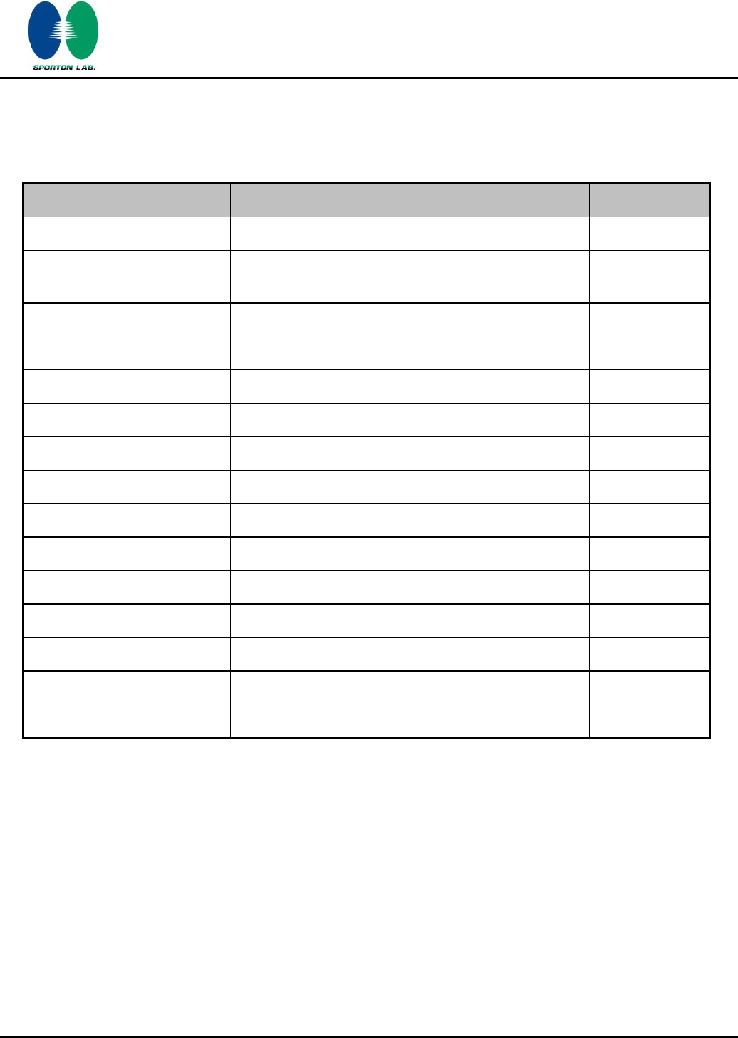
REVISION HISTORY
REPORT NO.
VERSION
DESCRIPTION
ISSUED DATE
FR1O2838A
Rev. 01
Initial issue of report
Jan. 21, 2012
FR1O2838A
Rev. 02
Update report for adding the units of measurement
on page 8
Feb. 14, 2012
SPORTON INTERNATIONAL INC.
Page Number
:
4 of 65
TEL : 886-3-327-3456
Report Issued Date
:
Feb. 14, 2012
FAX : 886-3-328-4978
Report Version
:
Rev. 02
FCC ID : L6AREF30LW
FCC RF Test Report
Report No. : FR1O2838A
SUMMARY OF TEST RESULT
Report
Section
FCC Rule
IC Rule
Description
Limit
Result
Remark
3.1
15.247(a)(1)
A8.4(2)
Number of Channels
≥ 15Chs
Pass
-
3.2
15.247(a)(1)
A8.1(a)
20dB Bandwidth
NA
Pass
-
3.2
-
Gen 4.6.1
99% Bandwidth
-
Pass
-
3.3
15.247(a)(1)
A8.1(b)
Channel Separation
≥ 2/3 of 20dB BW
Pass
-
3.4
15.247(a)(1)
A8.1(d)
Dwell Time of Each
Channel
≤ 0.4sec in
31.6sec period
Pass
-
3.5
15.247(b)(1)
A8.1(b)
Peak Output Power
≤ 125 mW
Pass
-
3.6
15.247(d)
A8.5
Frequency Band Edges
≤ 20dBc
Pass
-
3.7
15.247(d)
A8.5
Spurious Emission
< 20 dBc
Pass
-
3.8
15.207
Gen 7.2.4
AC Conducted Emission
15.207(a)
Pass
Under limit
8.50 dB at
0.366 MHz
3.9
15.247(d)
A8.5
Transmitter Radiated
Emission
15.209(a) &
15.247(d)
Pass
Under limit
5.52 dB at
2483.500 MHz
3.10
15.203 &
15.247(b)
A8.4
Antenna Requirement
N/A
Pass
-
SPORTON INTERNATIONAL INC.
Page Number
:
5 of 65
TEL : 886-3-327-3456
Report Issued Date
:
Feb. 14, 2012
FAX : 886-3-328-4978
Report Version
:
Rev. 02
FCC ID : L6AREF30LW
FCC RF Test Report
Report No. : FR1O2838A
1 General Description
1.1 Applicant
Research In Motion Limited
295 Phillip Street, Waterloo, Ontario, Canada
1.2 Manufacturer
Quanta Computer Inc.
No. 188, Wen Hwa 2nd Road, Kuei Shan Hsiang, Tao Yuan Shien, 333 Taiwan
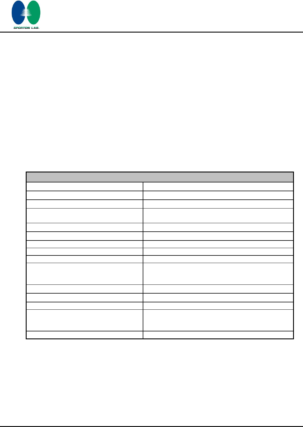
1.3 Feature of Equipment Under Test
Product Feature & Specification
Equipment
LTE band 13 / CDMA2000 BC0 & BC1 Tablet PC
Brand Name
RIM
Model Name
REF31LW
Marketing Name
P150-32***The stars "*" in model name can be 0 to 9, A
to Z or blank, for marking purpose.
FCC ID
L6AREF30LW
Tx/Rx Frequency Range
2400 MHz ~ 2483.5 MHz
Number of Channels
79
Carrier Frequency of Each Channel
2402+n*1 MHz; n=0~78
Channel Spacing
1 MHz
Maximum Output Power to Antenna
Bluetooth (1Mbps) : 8.04 dBm (0.0064 W)
Bluetooth EDR (2Mbps) : 8.14 dBm (0.0065 W)
Bluetooth EDR (3Mbps) : 8.67 dBm (0.0074 W)
Antenna Type
Fixed Internal Antenna with gain -2.97213 dBi
HW Version
DARU3MB1AD0 REVD
SW Version
1.0.0.0
Type of Modulation
Bluetooth (1Mbps) : GFSK
Bluetooth EDR (2Mbps) : π/4-DQPSK
Bluetooth EDR (3Mbps) : 8-DPSK
EUT Stage
Identical Prototype
Remark: The above EUT's information was declared by manufacturer. Please refer to the specifications
or user's manual for more detailed description.
SPORTON INTERNATIONAL INC.
Page Number
:
6 of 65
TEL : 886-3-327-3456
Report Issued Date
:
Feb. 14, 2012
FAX : 886-3-328-4978
Report Version
:
Rev. 02
FCC ID : L6AREF30LW
FCC RF Test Report
Report No. : FR1O2838A
1.4 Testing Site
Test Site
SPORTON INTERNATIONAL INC.
Test Site Location
No. 52, Hwa Ya 1st Rd., Hwa Ya Technology Park,
Kwei-Shan Hsiang, Tao Yuan Hsien, Taiwan, R.O.C.
TEL: +886-3-3273456 / FAX: +886-3-3284978
Test Site No.
Sporton Site No.
FCC/IC Registration No.
CO05-HY
03CH06-HY
722060/4086B-1
1.5 Applied Standards
According to the specifications of the manufacturer, the EUT must comply with the requirements of the
following standards:
FCC Part 15 Subpart C §15.247
FCC Public Notice DA 00-705
ANSI C63.4-2003
IC RSS-210 Issue 8
IC RSS-Gen Issue 3
Remark:
1. All test items were verified and recorded according to the standards and without any deviation
during the test.
2. This EUT has also been tested and complied with the requirements of FCC Part 15, Subpart B,
recorded in a separate test report.
SPORTON INTERNATIONAL INC.
Page Number
:
7 of 65
TEL : 886-3-327-3456
Report Issued Date
:
Feb. 14, 2012
FAX : 886-3-328-4978
Report Version
:
Rev. 02
FCC ID : L6AREF30LW
FCC RF Test Report
Report No. : FR1O2838A
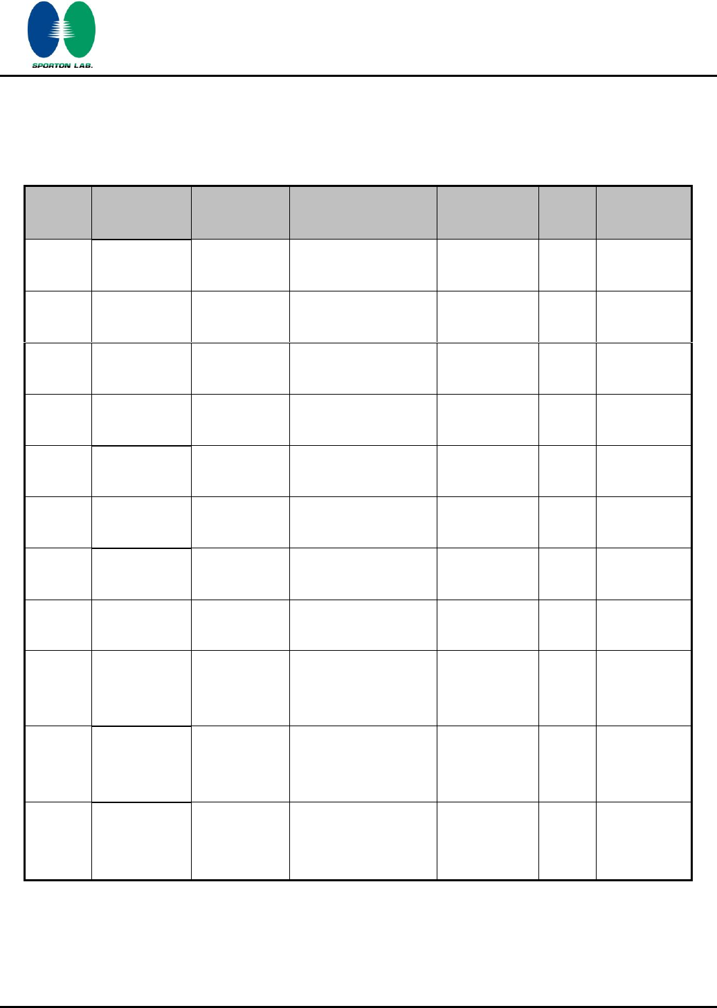
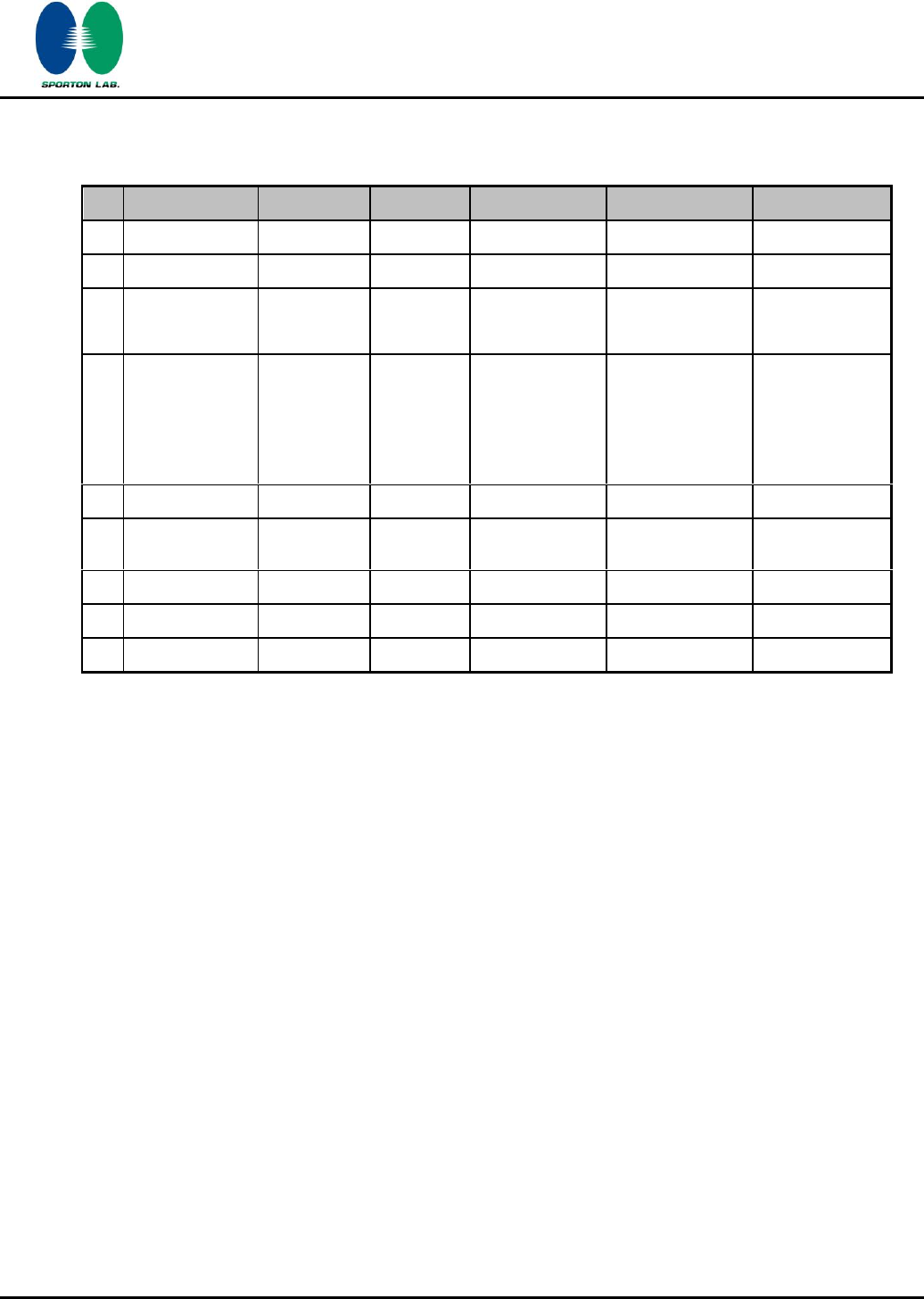
1.6 Ancillary Equipment List
Item
Equipment
Trade Name
Model Name
FCC ID
Data Cable
Power Cord
1.
System Simulator
R&S
CMU 200
N/A
N/A
Unshielded, 1.8 m
2.
WLAN AP
D-Link
DIR-628
KA2DIR628A2
N/A
Unshielded, 1.8 m
3.
Bluetooth Base
Station
R&S
CBT32
N/A
N/A
Unshielded, 1.8 m
4.
Notebook
DELL
P20G
FCC DoC
N/A
AC I/P:
Unshielded, 1.2 m
DC O/P:
Shielded, 1.8 m
5.
LCD Monitor
Acer
H223HQ
FCC DoC
N/A
Unshielded, 1.8 m
6.
Bluetooth
Earphone
Nokia
BH-102
PYAHS-107W
N/A
N/A
7.
Earphone
Ergotech
ET-E200
FCC DoC
Unshielded, 1.8 m
N/A
8.
iPod
Apple
A1199
FCC DoC
Shielded, 1.0 m
N/A
9.
iPod Earphone
Apple
N/A
FCC DoC
Shielded, 1.0 m
N/A
SPORTON INTERNATIONAL INC.
Page Number
:
8 of 65
TEL : 886-3-327-3456
Report Issued Date
:
Feb. 14, 2012
FAX : 886-3-328-4978
Report Version
:
Rev. 02
FCC ID : L6AREF30LW
FCC RF Test Report
Report No. : FR1O2838A
2 Test Configuration of Equipment Under Test
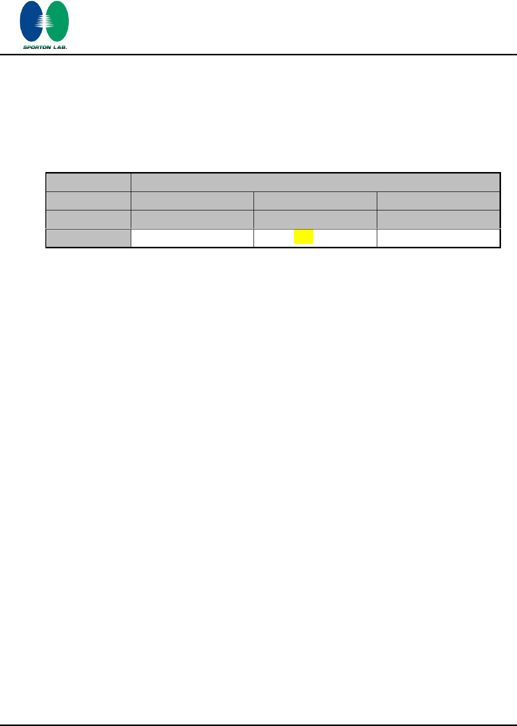
2.1 RF Output Power
Preliminary tests were performed in different data rate and recorded the RF output power in the
following table:
Band
Bluetooth RF Output Power
Channel
00
39
78
Frequency
2402
2441
2480
Peak Power
8.32 dBm
8.67 dBm
8.45 dBm
Remark:
1. All the test data for each data rate were verified, but only the worst case was reported.
2. The data rate was set in
3Mbps
for all the test items due to the highest RF output power.
3. The EUT is programmed to transmit signals continuously for all testing.
SPORTON INTERNATIONAL INC.
Page Number
:
9 of 65
TEL : 886-3-327-3456
Report Issued Date
:
Feb. 14, 2012
FAX : 886-3-328-4978
Report Version
:
Rev. 02
FCC ID : L6AREF30LW
FCC RF Test Report
Report No. : FR1O2838A
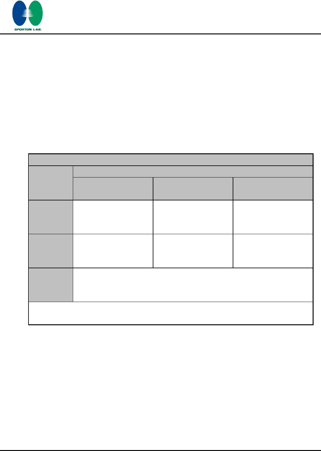
2.2 Test Mode
The EUT has been associated with peripherals pursuant to ANSI C63.4-2003 and configuration
operated in a manner tended to maximize its emission characteristics in a typical application.
Frequency range investigated: conduction (150 KHz to 30 MHz), radiation (9 KHz to the 10th harmonic
of the highest fundamental frequency or to 40 GHz, whichever is lower).
Pre-scanned tests, X, Y, Z in three orthogonal panels, were conducted to determine the final
configuration from all possible combinations, laptop / tablet modes.
The following tables are showing the test modes as the worst cases (E2plane) and recorded in this
report.
Test Cases
Test Item
Data Rate / Modulation
Bluetooth 1Mbps
GFSK
Bluetooth EDR 2Mbps
π/4-DQPSK
Bluetooth EDR 3Mbps
8-DPSK
Conducted
TCs
Mode 1: CH00_2402 MHz
Mode 2: CH39_2441 MHz
Mode 3: CH78_2480 MHz
Mode 4: CH00_2402 MHz
Mode 5: CH39_2441 MHz
Mode 6: CH78_2480 MHz
Mode 7: CH00_2402 MHz
Mode 8: CH39_2441 MHz
Mode 9: CH78_2480 MHz
Radiated
TCs
N/A
N/A
Mode 1: CH00_2402 MHz
Mode 2: CH39_2441 MHz
Mode 3: CH78_2480 MHz
AC
Conducted
Emission
Mode 1 : CDMA 850 Idle + Bluetooth Link + WLAN (2.4G) Link + Adapter 3 + Battery
1 + H Pattern + Earphone
Remark: For radiated TCs, the data rate was set in 3Mbps due to the highest RF output power; only
the data of these modes was reported. And all the tests were performance with Adapter 2
SPORTON INTERNATIONAL INC.
Page Number
:
10 of 65
TEL : 886-3-327-3456
Report Issued Date
:
Feb. 14, 2012
FAX : 886-3-328-4978
Report Version
:
Rev. 02
FCC ID : L6AREF30LW
FCC RF Test Report
Report No. : FR1O2838A
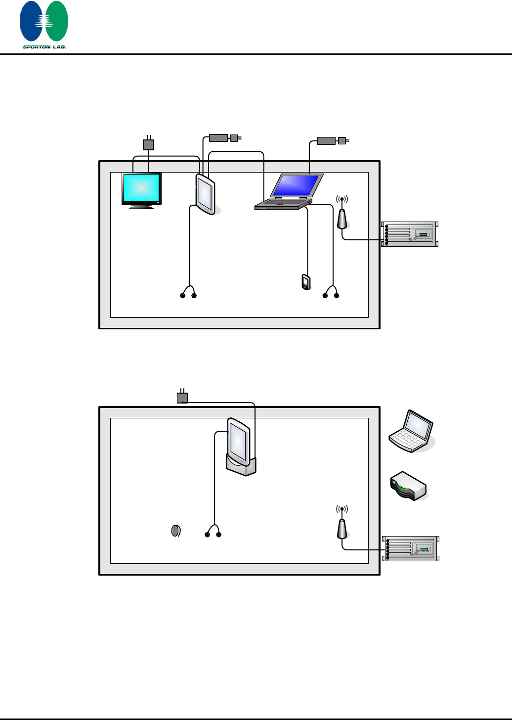
2.3 Connection Diagram of Test System
<Bluetooth Tx Mode>
LCD Monitor
iPod
Adapter
Adapter 120 Vac / 60 Hz
120 Vac / 60 Hz
Earphone
Dipole Antenna
EUT
Bluetooth
Base Station
Earphone
Adapter 120 Vac / 60 Hz
Notebook
<AC Conducted Emission Mode>
System Simulator
Dipole Antenna WLAN AP
Earphone
Bluetooth
Earphone
Adapter
120 Vac / 60 Hz
Notebook
EUT
2.4 RF Utility
For Bluetooth function, the RF utility, “Execute the Bluetooth Function” was installed in EUT which was
programmed in order to make the EUT into the engineering modes to contact with Bluetooth base
station for transmitting and receiving signals continuously.
SPORTON INTERNATIONAL INC.
Page Number
:
11 of 65
TEL : 886-3-327-3456
Report Issued Date
:
Feb. 14, 2012
FAX : 886-3-328-4978
Report Version
:
Rev. 02
FCC ID : L6AREF30LW
FCC RF Test Report
Report No. : FR1O2838A
3 Test Result
3.1 Number of Channel Measurement
3.1.1 Limits of Number of Hopping Frequency
Frequency hopping systems in the 2400-2483.5 MHz band shall use at least 15 channels.
3.1.2 Measuring Instruments
See list of measuring instruments of this test report.
3.1.3 Test Procedure
1. The testing follows FCC Public Notice DA 00-705 Measurement Guidelines.
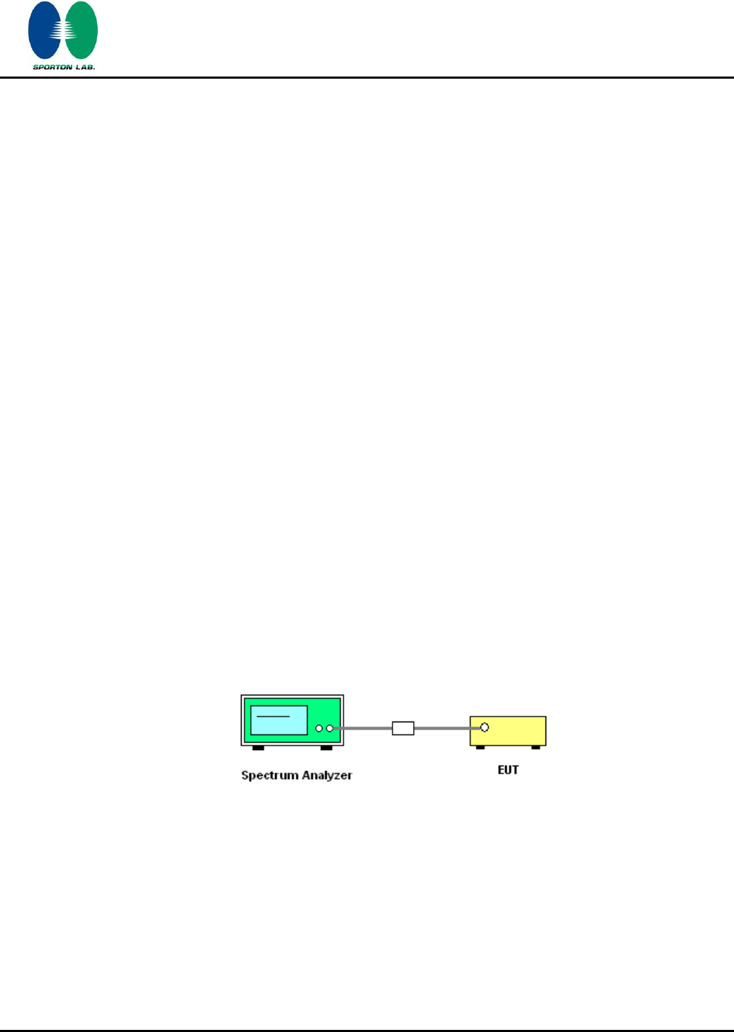
2. The RF output of EUT was connected to the spectrum analyzer by a low loss cable.
3. The modulation types of EUT are irrelevant to number of hopping channels deviation.
4. The EUT must have its hopping function enabled. Use the following spectrum analyzer settings:
Span = the frequency band of operation; RBW 1% of the span; VBW RBW; Sweep = auto;
Detector function = peak; Trace = max hold.
5. The number of hopping frequency used is defined as the device has the numbers of total
channel.
3.1.4 Test Setup
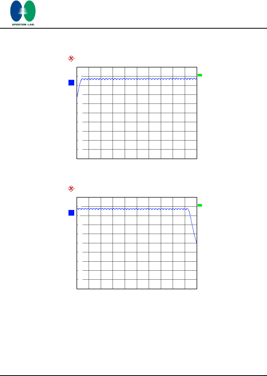
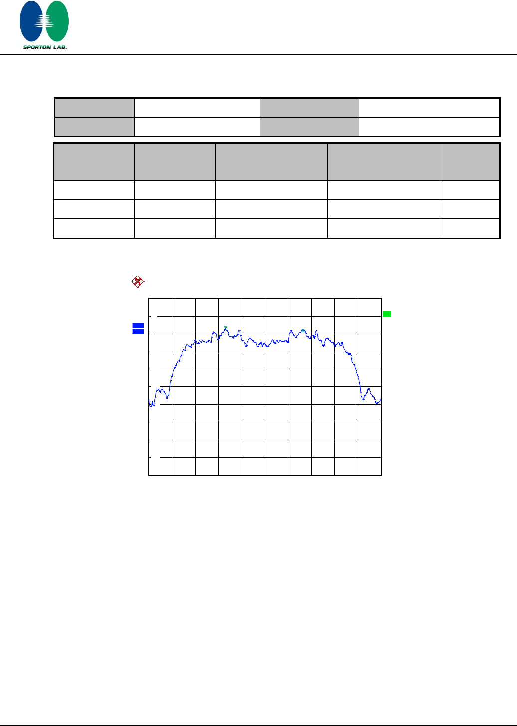
3.1.5 Test Result of Number of Hopping Frequency
Test Mode :
Mode 7~9
Temperature :
22~24℃
Test Engineer :
Reece Li
Relative Humidity :
53~57%
Number of Hopping Channels
(Channel)
Limits
(Channel)
Pass/Fail
79
> 15
Pass
SPORTON INTERNATIONAL INC.
Page Number
:
12 of 65
TEL : 886-3-327-3456
Report Issued Date
:
Feb. 14, 2012
FAX : 886-3-328-4978
Report Version
:
Rev. 02
FCC ID : L6AREF30LW
FCC RF Test Report
Report No. : FR1O2838A
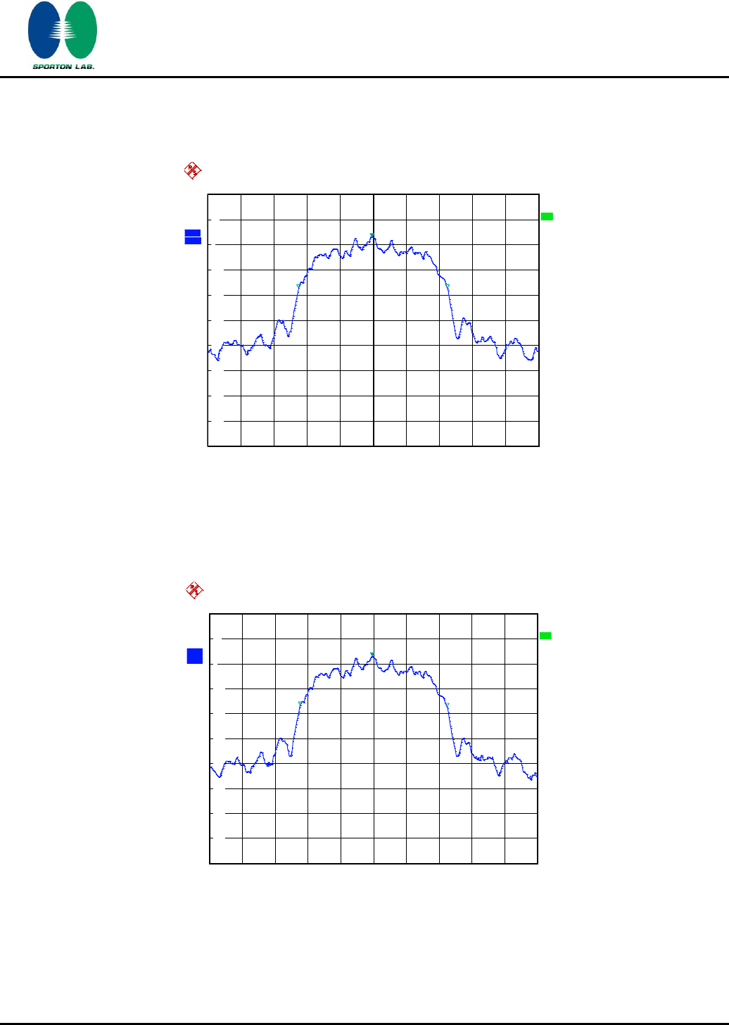
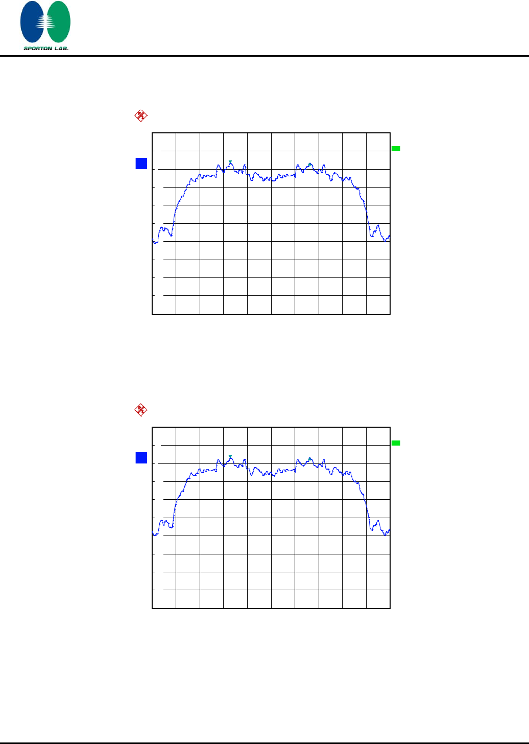
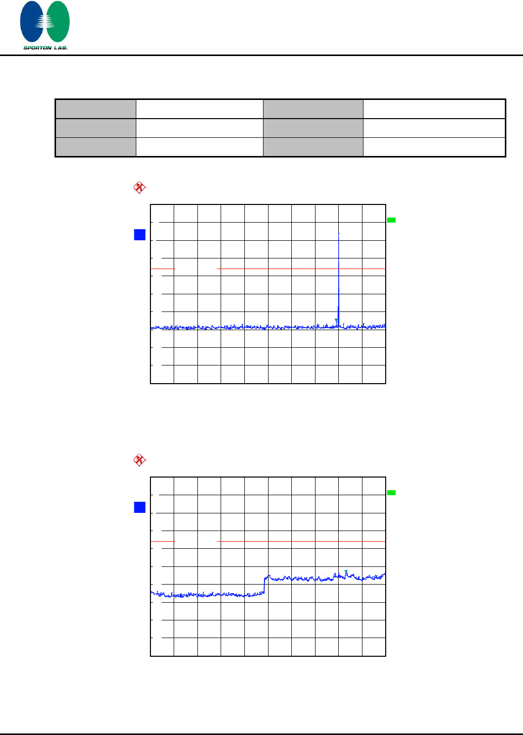
Number of Hopping Channel Plot on Channel 00 - 78
A
Offset
20.2 dB
LVL
Ref
20 dBm
Att
20 dB
*
*
Start
2.4 GHz
Stop
2.441 GHz
4.1 MHz/
*
*
3DB
RBW
1 MHz
VBW
1 MHz
SWT
500 ms
*
1 PK
MAXH
-80
-70
-60
-50
-40
-30
-20
-10
0
10
20
Date: 29.NOV.2011 22:15:57
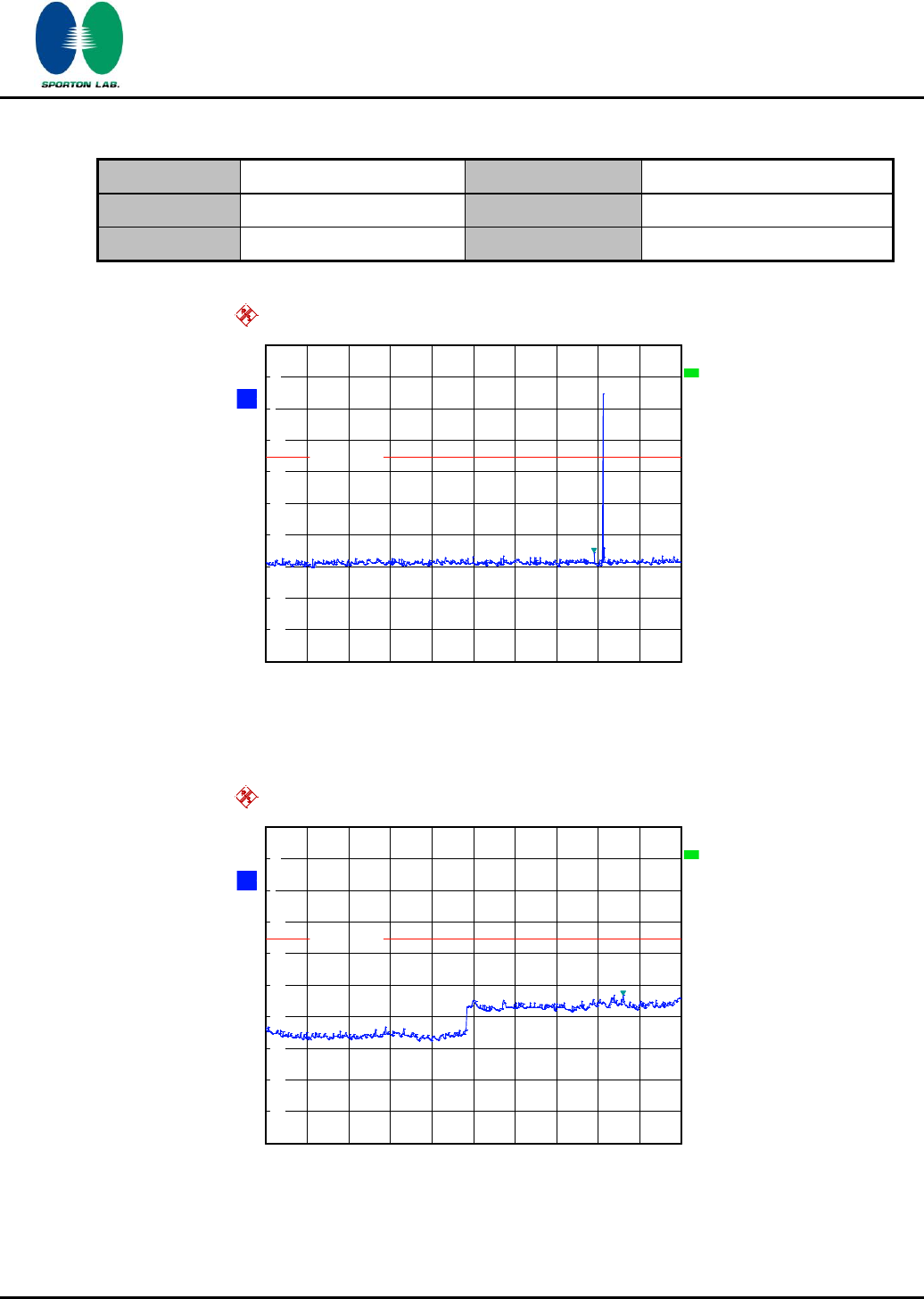
Ref
20 dBm
Att
20 dB
*
*
*
Offset
20.2 dB
A
LVL
3DB
RBW
1 MHz
VBW
1 MHz
SWT
500 ms
*
Start
2.441 GHz
Stop
2.4835 GHz
4.25 MHz/
*
1 PK
MAXH
-80
-70
-60
-50
-40
-30
-20
-10
0
10
20
Date: 29.NOV.2011 22:20:19
720510
SPORTON INTERNATIONAL INC.
Page Number
:
13 of 65
TEL : 886-3-327-3456
Report Issued Date
:
Feb. 14, 2012
FAX : 886-3-328-4978
Report Version
:
Rev. 02
FCC ID : L6AREF30LW
FCC RF Test Report
Report No. : FR1O2838A
3.2 20dB and 99% Bandwidth Measurement
3.2.1 Limit of 20dB Bandwidth
N/A
3.2.2 Measuring Instruments
See list of measuring instruments of this test report.
3.2.3 Test Procedures
1. The testing follows FCC Public Notice DA 00-705 Measurement Guidelines.
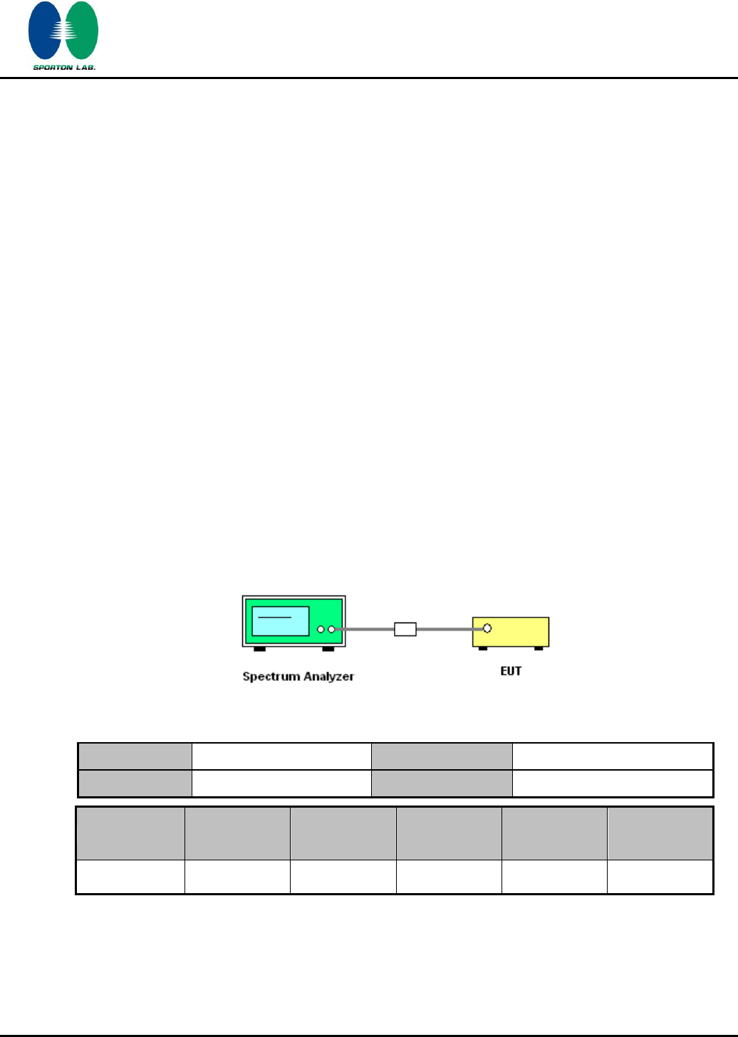
2. The RF output of EUT was connected to the spectrum analyzer by a low loss cable.
3. The EUT should be transmitting at its maximum data rate as the worst cases.
4. Use the following spectrum analyzer settings:
Span = approximately 2 to 3 times the 20 dB bandwidth, centered on a hopping channel;
RBW 1% of the 20 dB bandwidth; VBW RBW; Sweep = auto; Detector function = peak;
Trace = max hold.
5. The marker-delta reading at this point is the 20 dB bandwidth of the emission.
3.2.4 Test Setup
SPORTON INTERNATIONAL INC.
Page Number
:
14 of 65
TEL : 886-3-327-3456
Report Issued Date
:
Feb. 14, 2012
FAX : 886-3-328-4978
Report Version
:
Rev. 02
FCC ID : L6AREF30LW
FCC RF Test Report
Report No. : FR1O2838A
3.2.5 Test Result of 20dB Bandwidth
Test Mode :
Mode 1, 2, 3
Temperature :
22~24℃
Test Engineer :
Reece Li
Relative Humidity :
53~57%
Channel
Frequency (MHz)
20dB Bandwidth (MHz)
00
2402
0.904
39
2441
0.904
78
2480
0.904
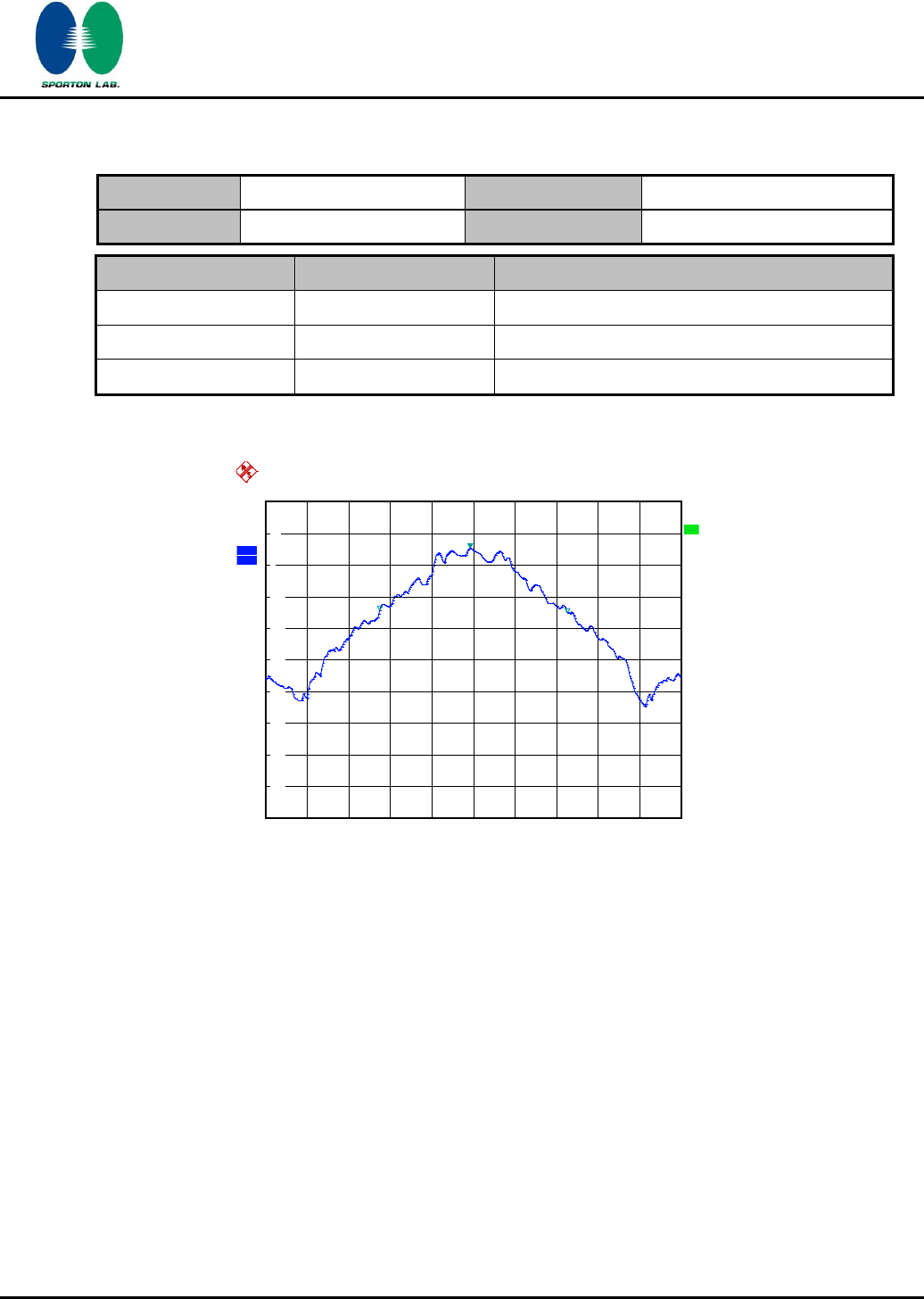
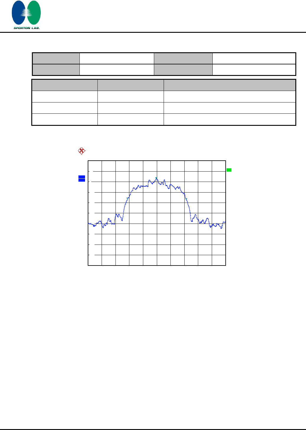
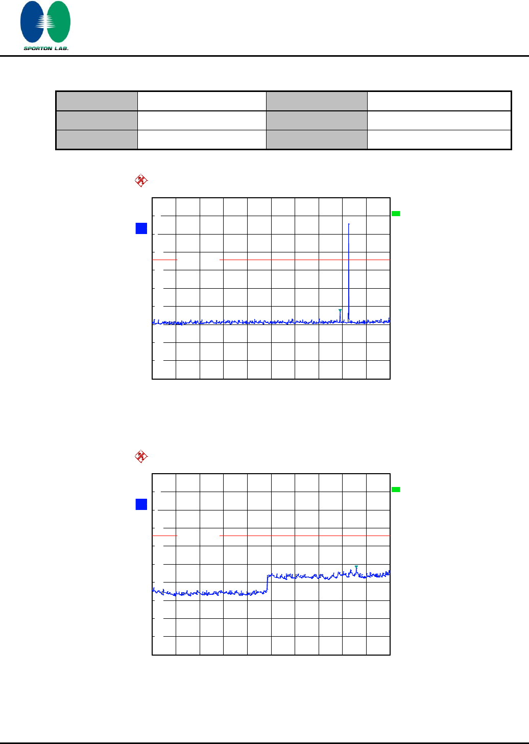
20 dB Bandwidth Plot on Channel 00
Ref
20 dBm
Att
20 dB
*
*
*
Offset
20.2 dB
1 PK
MAXH
A
LVL
3DB
RBW
30 kHz
VBW
300 kHz
SWT
2.5 ms
Center
2.402 GHz
Span
2 MHz
200 kHz/
-80
-70
-60
-50
-40
-30
-20
-10
0
10
20
1
Marker 1 [T1 ]
5.37 dBm
2.401984000 GHz
ndB [T1] 20.00 dB
BW 904.000000000 kHz
T1
Temp 1 [T1 ndB]
-14.24 dBm
2.401548000 GHz
T2
Temp 2 [T1 ndB]
-14.91 dBm
2.402452000 GHz
Date: 29.NOV.2011 20:42:43
720510

SPORTON INTERNATIONAL INC.
Page Number
:
15 of 65
TEL : 886-3-327-3456
Report Issued Date
:
Feb. 14, 2012
FAX : 886-3-328-4978
Report Version
:
Rev. 02
FCC ID : L6AREF30LW
FCC RF Test Report
Report No. : FR1O2838A
20 dB Bandwidth Plot on Channel 39
20 dB Bandwidth Plot on Channel 78
Ref
20 dBm
Att
20 dB
*
*
*
Offset
20.2 dB
1 PK
MAXH
A
LVL
3DB
RBW
30 kHz
VBW
300 kHz
SWT
2.5 ms
Center
2.441 GHz
Span
2 MHz
200 kHz/
-80
-70
-60
-50
-40
-30
-20
-10
0
10
20
1
Marker 1 [T1 ]
5.61 dBm
2.440984000 GHz
ndB [T1] 20.00 dB
BW 904.000000000 kHz
T1
Temp 1 [T1 ndB]
-14.54 dBm
2.440544000 GHz
T2
Temp 2 [T1 ndB]
-13.86 dBm
2.441448000 GHz
Date: 29.NOV.2011 20:43:53
Ref
20 dBm
Att
20 dB
*
*
*
Offset
20.2 dB
1 PK
MAXH
A
LVL
3DB
RBW
30 kHz
VBW
300 kHz
SWT
2.5 ms
Center
2.48 GHz
Span
2 MHz
200 kHz/
-80
-70
-60
-50
-40
-30
-20
-10
0
10
20
1
Marker 1 [T1 ]
5.41 dBm
2.479984000 GHz
ndB [T1] 20.00 dB
BW 904.000000000 kHz
T1
Temp 1 [T1 ndB]
-13.90 dBm
2.479548000 GHz
T2
Temp 2 [T1 ndB]
-14.77 dBm
2.480452000 GHz
Date: 29.NOV.2011 20:45:00
720510
720510

SPORTON INTERNATIONAL INC.
Page Number
:
16 of 65
TEL : 886-3-327-3456
Report Issued Date
:
Feb. 14, 2012
FAX : 886-3-328-4978
Report Version
:
Rev. 02
FCC ID : L6AREF30LW
FCC RF Test Report
Report No. : FR1O2838A
Test Mode :
Mode 4, 5, 6
Temperature :
22~24℃
Test Engineer :
Reece Li
Relative Humidity :
53~57%
Channel
Frequency (MHz)
20dB Bandwidth (MHz)
00
2402
1.344
39
2441
1.350
78
2480
1.344
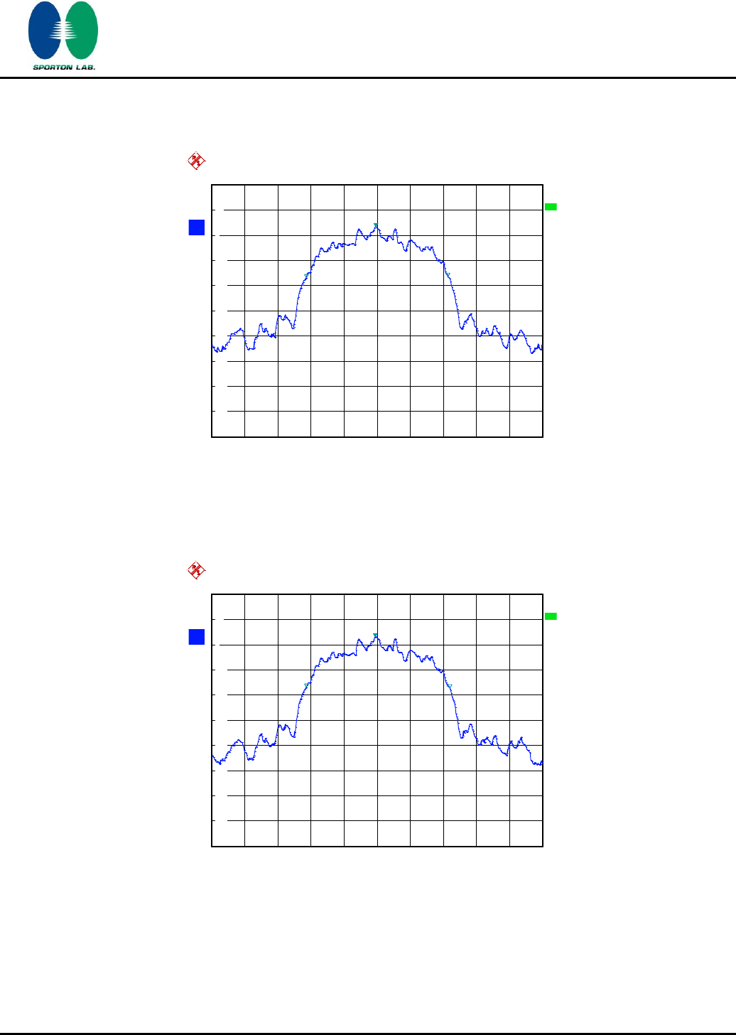
20 dB Bandwidth Plot on Channel 00
Ref
20 dBm
Att
20 dB
*
*
*
Offset
20.2 dB
1 PK
MAXH
A
LVL
3DB
RBW
30 kHz
VBW
300 kHz
SWT
5 ms
Center
2.402 GHz
Span
3 MHz
300 kHz/
-80
-70
-60
-50
-40
-30
-20
-10
0
10
20
1
Marker 1 [T1 ]
2.85 dBm
2.401988000 GHz
ndB [T1] 20.00 dB
BW 1.344000000 MHz
T1
Temp 1 [T1 ndB]
-17.05 dBm
2.401328000 GHz
T2
Temp 2 [T1 ndB]
-17.45 dBm
2.402672000 GHz
Date: 29.NOV.2011 20:46:04
720510
SPORTON INTERNATIONAL INC.
Page Number
:
17 of 65
TEL : 886-3-327-3456
Report Issued Date
:
Feb. 14, 2012
FAX : 886-3-328-4978
Report Version
:
Rev. 02
FCC ID : L6AREF30LW
FCC RF Test Report
Report No. : FR1O2838A
20 dB Bandwidth Plot on Channel 39
20 dB Bandwidth Plot on Channel 78
Ref
20 dBm
Att
20 dB
*
*
*
Offset
20.2 dB
1 PK
MAXH
A
LVL
3DB
RBW
30 kHz
VBW
300 kHz
SWT
5 ms
Center
2.441 GHz
Span
3 MHz
300 kHz/
-80
-70
-60
-50
-40
-30
-20
-10
0
10
20
1
Marker 1 [T1 ]
3.18 dBm
2.440988000 GHz
ndB [T1] 20.00 dB
BW 1.350000000 MHz
T1
Temp 1 [T1 ndB]
-17.16 dBm
2.440322000 GHz
T2
Temp 2 [T1 ndB]
-17.13 dBm
2.441672000 GHz
Date: 29.NOV.2011 20:46:45
Ref
20 dBm
Att
20 dB
*
*
*
Offset
20.2 dB
1 PK
MAXH
A
LVL
3DB
RBW
30 kHz
VBW
300 kHz
SWT
5 ms
Center
2.48 GHz
Span
3 MHz
300 kHz/
-80
-70
-60
-50
-40
-30
-20
-10
0
10
20
1
Marker 1 [T1 ]
3.03 dBm
2.479988000 GHz
ndB [T1] 20.00 dB
BW 1.344000000 MHz
T1
Temp 1 [T1 ndB]
-16.71 dBm
2.479328000 GHz
T2
Temp 2 [T1 ndB]
-17.04 dBm
2.480672000 GHz
Date: 29.NOV.2011 20:47:49
720510
720510
SPORTON INTERNATIONAL INC.
Page Number
:
18 of 65
TEL : 886-3-327-3456
Report Issued Date
:
Feb. 14, 2012
FAX : 886-3-328-4978
Report Version
:
Rev. 02
FCC ID : L6AREF30LW
FCC RF Test Report
Report No. : FR1O2838A
Test Mode :
Mode 7, 8, 9
Temperature :
22~24℃
Test Engineer :
Reece Li
Relative Humidity :
53~57%
Channel
Frequency (MHz)
20dB Bandwidth (MHz)
00
2402
1.284
39
2441
1.284
78
2480
1.302
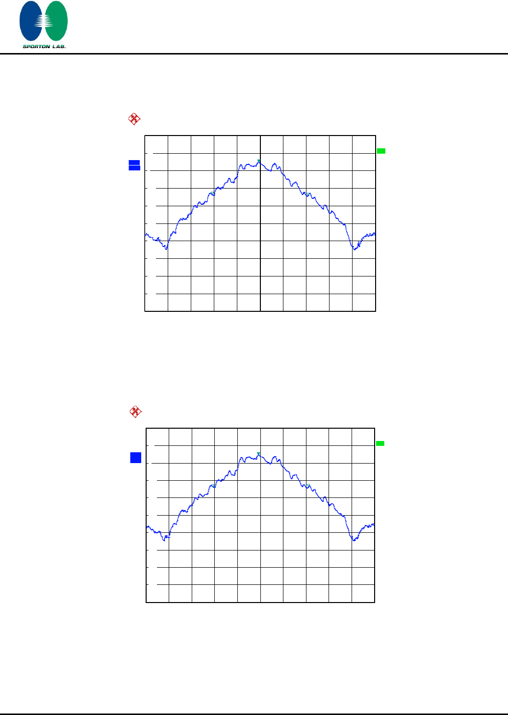
20 dB Bandwidth Plot on Channel 00
A
Offset
20.2 dB
LVL
Ref
20 dBm
Center
2.402 GHz
Span
3 MHz
300 kHz/
Att
20 dB
*
3DB
RBW
30 kHz
SWT
5 ms
*
VBW
300 kHz
*
1 PK
MAXH
-80
-70
-60
-50
-40
-30
-20
-10
0
10
20
1
Marker 1 [T1 ]
2.85 dBm
2.401988000 GHz
ndB [T1] 20.00 dB
BW 1.284000000 MHz
T1
Temp 1 [T1 ndB]
-16.74 dBm
2.401358000 GHz
T2
Temp 2 [T1 ndB]
-17.19 dBm
2.402642000 GHz
Date: 29.NOV.2011 21:39:22
720510
SPORTON INTERNATIONAL INC.
Page Number
:
19 of 65
TEL : 886-3-327-3456
Report Issued Date
:
Feb. 14, 2012
FAX : 886-3-328-4978
Report Version
:
Rev. 02
FCC ID : L6AREF30LW
FCC RF Test Report
Report No. : FR1O2838A
20 dB Bandwidth Plot on Channel 39
20 dB Bandwidth Plot on Channel 78
A
Offset
20.2 dB
LVL
Ref
20 dBm
Center
2.441 GHz
Span
3 MHz
300 kHz/
Att
20 dB
*
3DB
RBW
30 kHz
SWT
5 ms
*
VBW
300 kHz
*
1 PK
MAXH
-80
-70
-60
-50
-40
-30
-20
-10
0
10
20
1
Marker 1 [T1 ]
3.38 dBm
2.440988000 GHz
ndB [T1] 20.00 dB
BW 1.284000000 MHz
T1
Temp 1 [T1 ndB]
-16.84 dBm
2.440358000 GHz
T2
Temp 2 [T1 ndB]
-16.37 dBm
2.441642000 GHz
Date: 29.NOV.2011 21:39:50
A
Offset
20.2 dB
LVL
Ref
20 dBm
Center
2.48 GHz
Span
3 MHz
300 kHz/
Att
20 dB
*
3DB
RBW
30 kHz
SWT
5 ms
*
VBW
300 kHz
*
1 PK
MAXH
-80
-70
-60
-50
-40
-30
-20
-10
0
10
20
1
Marker 1 [T1 ]
3.11 dBm
2.479982000 GHz
ndB [T1] 20.00 dB
BW 1.302000000 MHz
T1
Temp 1 [T1 ndB]
-16.84 dBm
2.479358000 GHz
T2
Temp 2 [T1 ndB]
-17.15 dBm
2.480660000 GHz
Date: 29.NOV.2011 21:38:53
720510
720510

SPORTON INTERNATIONAL INC.
Page Number
:
20 of 65
TEL : 886-3-327-3456
Report Issued Date
:
Feb. 14, 2012
FAX : 886-3-328-4978
Report Version
:
Rev. 02
FCC ID : L6AREF30LW
FCC RF Test Report
Report No. : FR1O2838A
3.2.6 Test Result of 99% Occupied Bandwidth
Test Mode :
Mode 1, 2, 3
Temperature :
22~24℃
Test Engineer :
Reece Li
Relative Humidity :
53~57%
Channel
Frequency (MHz)
99% Occupied Bandwidth (MHz)
00
2402
0.828
39
2441
0.832
78
2480
0.836
99% Bandwidth Plot on Channel 00
A
Offset
20.2 dB
LVL
Ref
20 dBm
Center
2.402 GHz
Span
2 MHz
200 kHz/
Att
20 dB
*
*
*
3DB
RBW
30 kHz
VBW
30 kHz
SWT
5 ms
*
1 SA
MAXH
-80
-70
-60
-50
-40
-30
-20
-10
0
10
20
1
Marker 1 [T1 ]
4.47 dBm
2.401988000 GHz
OBW828.000000000 kHz
T1
Temp 1 [T1 OBW]
-13.99 dBm
2.401588000 GHz
T2
Temp 2 [T1 OBW]
-14.33 dBm
2.402416000 GHz
Date: 29.NOV.2011 22:07:48
720510
SPORTON INTERNATIONAL INC.
Page Number
:
21 of 65
TEL : 886-3-327-3456
Report Issued Date
:
Feb. 14, 2012
FAX : 886-3-328-4978
Report Version
:
Rev. 02
FCC ID : L6AREF30LW
FCC RF Test Report
Report No. : FR1O2838A
99% Occupied Bandwidth Plot on Channel 39
99% Occupied Bandwidth Plot on Channel 78
A
Offset
20.2 dB
LVL
Ref
20 dBm
Center
2.441 GHz
Span
2 MHz
200 kHz/
Att
20 dB
*
*
*
3DB
RBW
30 kHz
VBW
30 kHz
SWT
5 ms
*
1 SA
MAXH
-80
-70
-60
-50
-40
-30
-20
-10
0
10
20
1
Marker 1 [T1 ]
4.94 dBm
2.440988000 GHz
OBW832.000000000 kHz
T1
Temp 1 [T1 OBW]
-13.53 dBm
2.440584000 GHz
T2
Temp 2 [T1 OBW]
-13.93 dBm
2.441416000 GHz
Date: 29.NOV.2011 22:08:27
A
Offset
20.2 dB
LVL
Ref
20 dBm
Center
2.48 GHz
Span
2 MHz
200 kHz/
Att
20 dB
*
*
*
3DB
RBW
30 kHz
VBW
30 kHz
SWT
5 ms
*
1 SA
MAXH
-80
-70
-60
-50
-40
-30
-20
-10
0
10
20
1
Marker 1 [T1 ]
4.76 dBm
2.479984000 GHz
OBW836.000000000 kHz
T1
Temp 1 [T1 OBW]
-13.77 dBm
2.479584000 GHz
T2
Temp 2 [T1 OBW]
-13.47 dBm
2.480420000 GHz
Date: 29.NOV.2011 22:07:12
720510
720510

SPORTON INTERNATIONAL INC.
Page Number
:
22 of 65
TEL : 886-3-327-3456
Report Issued Date
:
Feb. 14, 2012
FAX : 886-3-328-4978
Report Version
:
Rev. 02
FCC ID : L6AREF30LW
FCC RF Test Report
Report No. : FR1O2838A
Test Mode :
Mode 4, 5, 6
Temperature :
22~24℃
Test Engineer :
Reece Li
Relative Humidity :
53~57%
Channel
Frequency (MHz)
99% Occupied Bandwidth (MHz)
00
2402
1.196
39
2441
1.196
78
2480
1.196
99% Bandwidth Plot on Channel 00
A
Offset
20.2 dB
LVL
Ref
20 dBm
Center
2.402 GHz
Span
2 MHz
200 kHz/
Att
20 dB
*
*
*
3DB
RBW
30 kHz
VBW
30 kHz
SWT
5 ms
*
1 SA
MAXH
-80
-70
-60
-50
-40
-30
-20
-10
0
10
20
1
Marker 1 [T1 ]
2.09 dBm
2.401984000 GHz
OBW 1.196000000 MHz
T1
Temp 1 [T1 OBW]
-12.26 dBm
2.401400000 GHz
T2
Temp 2 [T1 OBW]
-13.45 dBm
2.402596000 GHz
Date: 29.NOV.2011 22:04:56
720510

SPORTON INTERNATIONAL INC.
Page Number
:
23 of 65
TEL : 886-3-327-3456
Report Issued Date
:
Feb. 14, 2012
FAX : 886-3-328-4978
Report Version
:
Rev. 02
FCC ID : L6AREF30LW
FCC RF Test Report
Report No. : FR1O2838A
99% Occupied Bandwidth Plot on Channel 39
99% Occupied Bandwidth Plot on Channel 78
A
Offset
20.2 dB
LVL
Ref
20 dBm
Center
2.441 GHz
Span
2 MHz
200 kHz/
Att
20 dB
*
*
*
3DB
RBW
30 kHz
VBW
30 kHz
SWT
5 ms
*
1 SA
MAXH
-80
-70
-60
-50
-40
-30
-20
-10
0
10
20
1
Marker 1 [T1 ]
2.78 dBm
2.440984000 GHz
OBW 1.196000000 MHz
T1
Temp 1 [T1 OBW]
-11.52 dBm
2.440400000 GHz
T2
Temp 2 [T1 OBW]
-12.81 dBm
2.441596000 GHz
Date: 29.NOV.2011 22:03:06
A
Offset
20.2 dB
LVL
Ref
20 dBm
Center
2.48 GHz
Span
2 MHz
200 kHz/
Att
20 dB
*
*
*
3DB
RBW
30 kHz
VBW
30 kHz
SWT
5 ms
*
1 SA
MAXH
-80
-70
-60
-50
-40
-30
-20
-10
0
10
20
1
Marker 1 [T1 ]
2.45 dBm
2.479988000 GHz
OBW 1.196000000 MHz
T1
Temp 1 [T1 OBW]
-11.65 dBm
2.479400000 GHz
T2
Temp 2 [T1 OBW]
-13.01 dBm
2.480596000 GHz
Date: 29.NOV.2011 22:05:38
720510
720510

SPORTON INTERNATIONAL INC.
Page Number
:
24 of 65
TEL : 886-3-327-3456
Report Issued Date
:
Feb. 14, 2012
FAX : 886-3-328-4978
Report Version
:
Rev. 02
FCC ID : L6AREF30LW
FCC RF Test Report
Report No. : FR1O2838A
Test Mode :
Mode 7, 8, 9
Temperature :
22~24℃
Test Engineer :
Reece Li
Relative Humidity :
53~57%
Channel
Frequency (MHz)
99% Occupied Bandwidth (MHz)
00
2402
1.172
39
2441
1.172
78
2480
1.172
99% Bandwidth Plot on Channel 00
A
Offset
20.2 dB
LVL
Ref
20 dBm
Center
2.402 GHz
Span
2 MHz
200 kHz/
Att
20 dB
*
*
*
3DB
RBW
30 kHz
VBW
30 kHz
SWT
5 ms
*
1 SA
MAXH
-80
-70
-60
-50
-40
-30
-20
-10
0
10
20
1
Marker 1 [T1 ]
2.33 dBm
2.401984000 GHz
OBW 1.172000000 MHz
T1
Temp 1 [T1 OBW]
-12.60 dBm
2.401420000 GHz
T2
Temp 2 [T1 OBW]
-11.87 dBm
2.402592000 GHz
Date: 29.NOV.2011 21:59:49
720510

SPORTON INTERNATIONAL INC.
Page Number
:
25 of 65
TEL : 886-3-327-3456
Report Issued Date
:
Feb. 14, 2012
FAX : 886-3-328-4978
Report Version
:
Rev. 02
FCC ID : L6AREF30LW
FCC RF Test Report
Report No. : FR1O2838A
99% Occupied Bandwidth Plot on Channel 39
99% Occupied Bandwidth Plot on Channel 78
A
Offset
20.2 dB
LVL
Ref
20 dBm
Center
2.441 GHz
Span
2 MHz
200 kHz/
Att
20 dB
*
*
*
3DB
RBW
30 kHz
VBW
30 kHz
SWT
5 ms
*
1 SA
MAXH
-80
-70
-60
-50
-40
-30
-20
-10
0
10
20
1
Marker 1 [T1 ]
2.80 dBm
2.440984000 GHz
OBW 1.172000000 MHz
T1
Temp 1 [T1 OBW]
-12.26 dBm
2.440420000 GHz
T2
Temp 2 [T1 OBW]
-11.19 dBm
2.441592000 GHz
Date: 29.NOV.2011 22:00:26
A
Offset
20.2 dB
LVL
Ref
20 dBm
Center
2.48 GHz
Span
2 MHz
200 kHz/
Att
20 dB
*
*
*
3DB
RBW
30 kHz
VBW
30 kHz
SWT
5 ms
*
1 SA
MAXH
-80
-70
-60
-50
-40
-30
-20
-10
0
10
20
1
Marker 1 [T1 ]
2.60 dBm
2.479984000 GHz
OBW 1.172000000 MHz
T1
Temp 1 [T1 OBW]
-12.36 dBm
2.479420000 GHz
T2
Temp 2 [T1 OBW]
-11.17 dBm
2.480592000 GHz
Date: 29.NOV.2011 21:59:08
720510
720510
SPORTON INTERNATIONAL INC.
Page Number
:
26 of 65
TEL : 886-3-327-3456
Report Issued Date
:
Feb. 14, 2012
FAX : 886-3-328-4978
Report Version
:
Rev. 02
FCC ID : L6AREF30LW
FCC RF Test Report
Report No. : FR1O2838A
3.3 Hopping Channel Separation Measurement
3.3.1 Limit of Hopping Channel Separation
Frequency hopping systems operating in the 2400-2483.5 MHz band may have hopping channel
carrier frequencies that are separated by 25 KHz or two-thirds of the 20 dB bandwidth of the hopping
channel, whichever is greater.
3.3.2 Measuring Instruments
See list of measuring instruments of this test report.
3.3.3 Test Procedures
1. Please refer FCC Public Notice DA 00-705 Measurement Guidelines.
2. The RF output of EUT was connected to the spectrum analyzer by a low loss cable.
3. The EUT should be transmitting at its maximum data rate as the worst cases.
4. Use the following spectrum analyzer settings:
Span = wide enough to capture the peaks of two adjacent channels; RBW 1% of the span;
VBW RBW; Sweep = auto; Detector function = peak; Trace = max hold.
5. Use the marker-delta function to determine the separation between the peaks of the adjacent
channels.
3.3.4 Test Setup
SPORTON INTERNATIONAL INC.
Page Number
:
27 of 65
TEL : 886-3-327-3456
Report Issued Date
:
Feb. 14, 2012
FAX : 886-3-328-4978
Report Version
:
Rev. 02
FCC ID : L6AREF30LW
FCC RF Test Report
Report No. : FR1O2838A
3.3.5 Test Result of Hopping Channel Separation
Test Mode :
Mode 7, 8, 9
Temperature :
22~24℃
Test Engineer :
Reece Li
Relative Humidity :
53~57%
Channel
Frequency
(MHz)
Frequency Separation
(MHz)
(2/3 of 20dB BW)
Limits (MHz)
Pass/Fail
00
2402
1.002
0.8560
Pass
39
2441
1.002
0.8560
Pass
78
2480
1.002
0.8680
Pass
Channel Separation Plot on Channel 00 - 01
A
Offset
20.2 dB
LVL
Ref
20 dBm
Center
2.4025 GHz
Span
3 MHz
300 kHz/
Att
20 dB
*
3DB
RBW
30 kHz
SWT
5 ms
*
VBW
100 kHz
*
1 PK
MAXH
-80
-70
-60
-50
-40
-30
-20
-10
0
10
20
1
Marker 1 [T1 ]
2.80 dBm
2.401990000 GHz
2
Delta 2 [T1 ]
0.12 dB
1.002000000 MHz
Date: 29.NOV.2011 21:17:48
720510
SPORTON INTERNATIONAL INC.
Page Number
:
28 of 65
TEL : 886-3-327-3456
Report Issued Date
:
Feb. 14, 2012
FAX : 886-3-328-4978
Report Version
:
Rev. 02
FCC ID : L6AREF30LW
FCC RF Test Report
Report No. : FR1O2838A
Channel Separation Plot on Channel 39 - 40
Channel Separation Plot on Channel 77 - 78
A
Offset
20.2 dB
LVL
Ref
20 dBm
Center
2.4415 GHz
Span
3 MHz
300 kHz/
Att
20 dB
*
3DB
RBW
30 kHz
SWT
5 ms
*
VBW
100 kHz
*
1 PK
MAXH
-80
-70
-60
-50
-40
-30
-20
-10
0
10
20
1
Marker 1 [T1 ]
3.37 dBm
2.440984000 GHz
2
Delta 2 [T1 ]
0.04 dB
1.002000000 MHz
Date: 29.NOV.2011 21:18:49
Ref
20 dBm
Att
20 dB
*
*
*
Offset
20.2 dB
1 PK
MAXH
A
LVL
3DB
RBW
30 kHz
VBW
100 kHz
SWT
5 ms
Center
2.4795 GHz
Span
3 MHz
300 kHz/
-80
-70
-60
-50
-40
-30
-20
-10
0
10
20
1
Marker 1 [T1 ]
3.14 dBm
2.478984000 GHz
2
Delta 2 [T1 ]
0.06 dB
1.002000000 MHz
Date: 29.NOV.2011 21:24:54
720510
720510
SPORTON INTERNATIONAL INC.
Page Number
:
29 of 65
TEL : 886-3-327-3456
Report Issued Date
:
Feb. 14, 2012
FAX : 886-3-328-4978
Report Version
:
Rev. 02
FCC ID : L6AREF30LW
FCC RF Test Report
Report No. : FR1O2838A
3.4 Dwell Time Measurement
3.4.1 Limit of Dwell Time
The average time of occupancy on any channel shall not be greater than 0.4 seconds within a period
of 0.4 seconds multiplied by the number of hopping channels employed.
3.4.2 Measuring Instruments
See list of measuring instruments of this test report.
3.4.3 Test Procedures
1. The testing follows FCC Public Notice DA 00-705 Measurement Guidelines.
2. The RF output of EUT was connected to the spectrum analyzer by a low loss cable.
3. The EUT should be transmitting at its maximum data rate as the worst cases.
4. The EUT must have its hopping function enabled. Use the following spectrum analyzer settings:
Span = zero span, centered on a hopping channel; RBW = 1 MHz; VBW RBW; Sweep = as
necessary to capture the entire dwell time per hopping channel; Detector function = peak;
Trace = max hold.
5. Use the marker-delta function to calculate the dwell time.
3.4.4 Test Setup
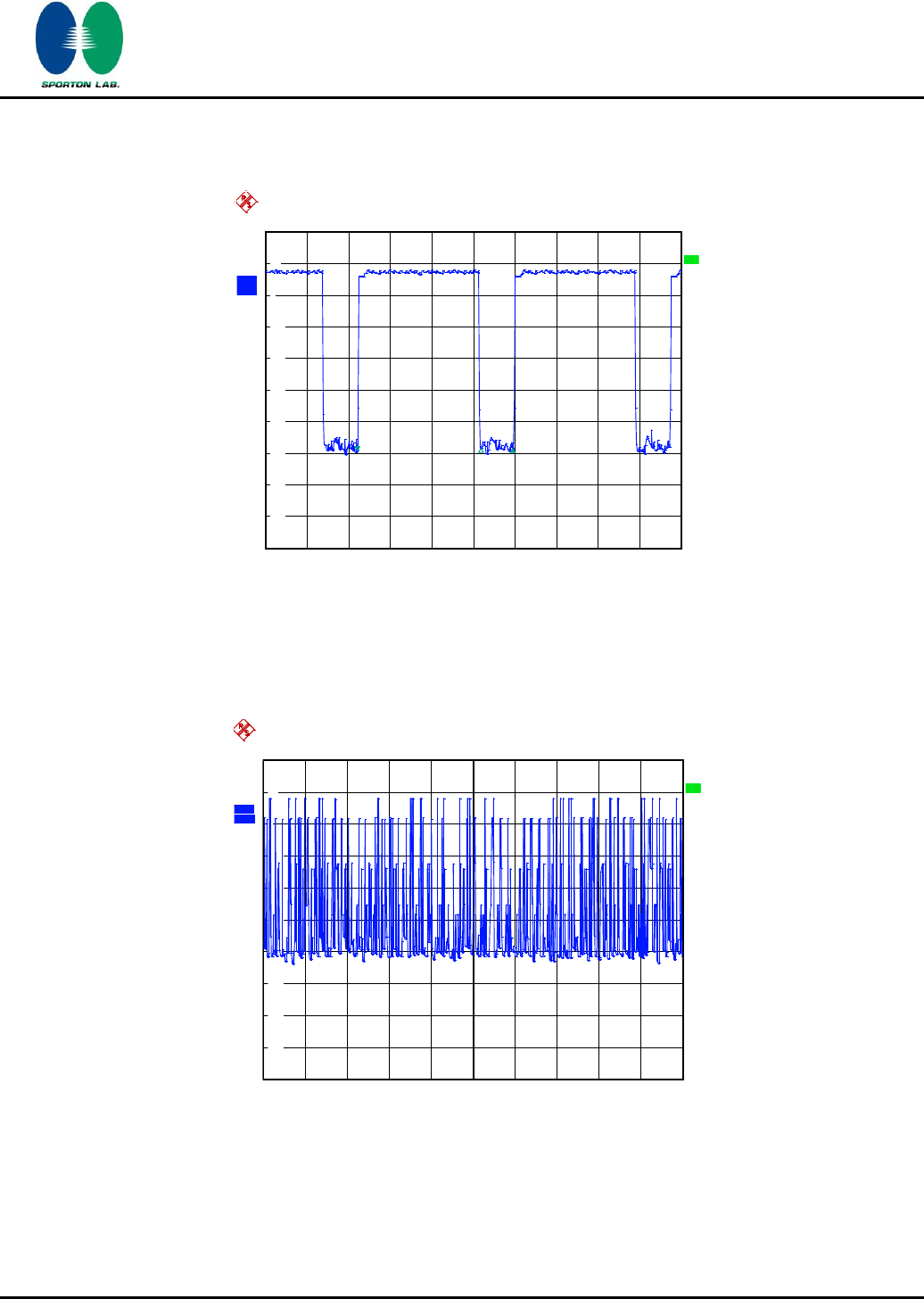
3.4.5 Test Result of Dwell Time
Test Mode :
Mode 8
Temperature :
22~24℃
Test Engineer :
Reece Li
Relative Humidity :
53~57%
Package Mode
Average
Hopping
Channel
Package
Transfer Time
(usec)
Dwell Time
(sec)
Limits
(sec)
Pass/Fail
3DH5
3.10
2980.00
0.29
0.4
Pass
Remark:
1. Dwell Time=79(channels) x 0.4(s) x average hopping channel x package transfer time
2. 79 channels come from the Hopping Channel number.
3. Average Hopping Channel = hops/sweep time
4. t: Package Transfer Time(us)
SPORTON INTERNATIONAL INC.
Page Number
:
30 of 65
TEL : 886-3-327-3456
Report Issued Date
:
Feb. 14, 2012
FAX : 886-3-328-4978
Report Version
:
Rev. 02
FCC ID : L6AREF30LW
FCC RF Test Report
Report No. : FR1O2838A
3DH5 Dwell Time (One Pulse) Plot on Channel 39
3DH5 Dwell Time (Count Pulses) Plot on Channel 39
Ref
20 dBm
Att
20 dB
*
*
Offset
20.2 dB
Center 2.441 GHz
1 ms/
1 PK
MAXH
A
SGL
LVL
3DB
RBW
1 MHz
VBW
1 MHz
SWT
10 ms
-80
-70
-60
-50
-40
-30
-20
-10
0
10
20
1
Marker 1 [T1 ]
-49.28 dBm
2.200000 ms
2
Delta 2 [T1 ]
0.94 dB
2.980000 ms
3
Delta 3 [T1 ]
0.89 dB
3.740000 ms
Date: 29.NOV.2011 21:11:59
A
Offset
20.2 dB
LVL
Ref
20 dBm
Att
20 dB
*
3DB
RBW
1 MHz
VBW
1 MHz
*
Center 2.441 GHz
1 s/
SWT
10 s
1 PK
MAXH
SGL
-80
-70
-60
-50
-40
-30
-20
-10
0
10
20
Date: 29.NOV.2011 21:10:01
720510
720510
SPORTON INTERNATIONAL INC.
Page Number
:
31 of 65
TEL : 886-3-327-3456
Report Issued Date
:
Feb. 14, 2012
FAX : 886-3-328-4978
Report Version
:
Rev. 02
FCC ID : L6AREF30LW
FCC RF Test Report
Report No. : FR1O2838A
3.5 Peak Output Power Measurement
3.5.1 Limit of Peak Output Power
Section 15.247 (b) The maximum peak conducted output power of the intentional radiator shall not
exceed the following: (1) For frequency hopping systems operating in the 2400-2483.5 MHz band
employing at least 75 non-overlapping hopping channels, and all frequency hopping systems in the
5725-5850 MHz band: 1 watt. For all other frequency hopping systems in the 2400-2483.5 MHz band
0.125 watts. The power limit for 1Mbps is 1watt, and for 2Mbps, and 3Mbps are 0.125 watts.
3.5.2 Measuring Instruments
See list of measuring instruments of this test report.
3.5.3 Test Procedures
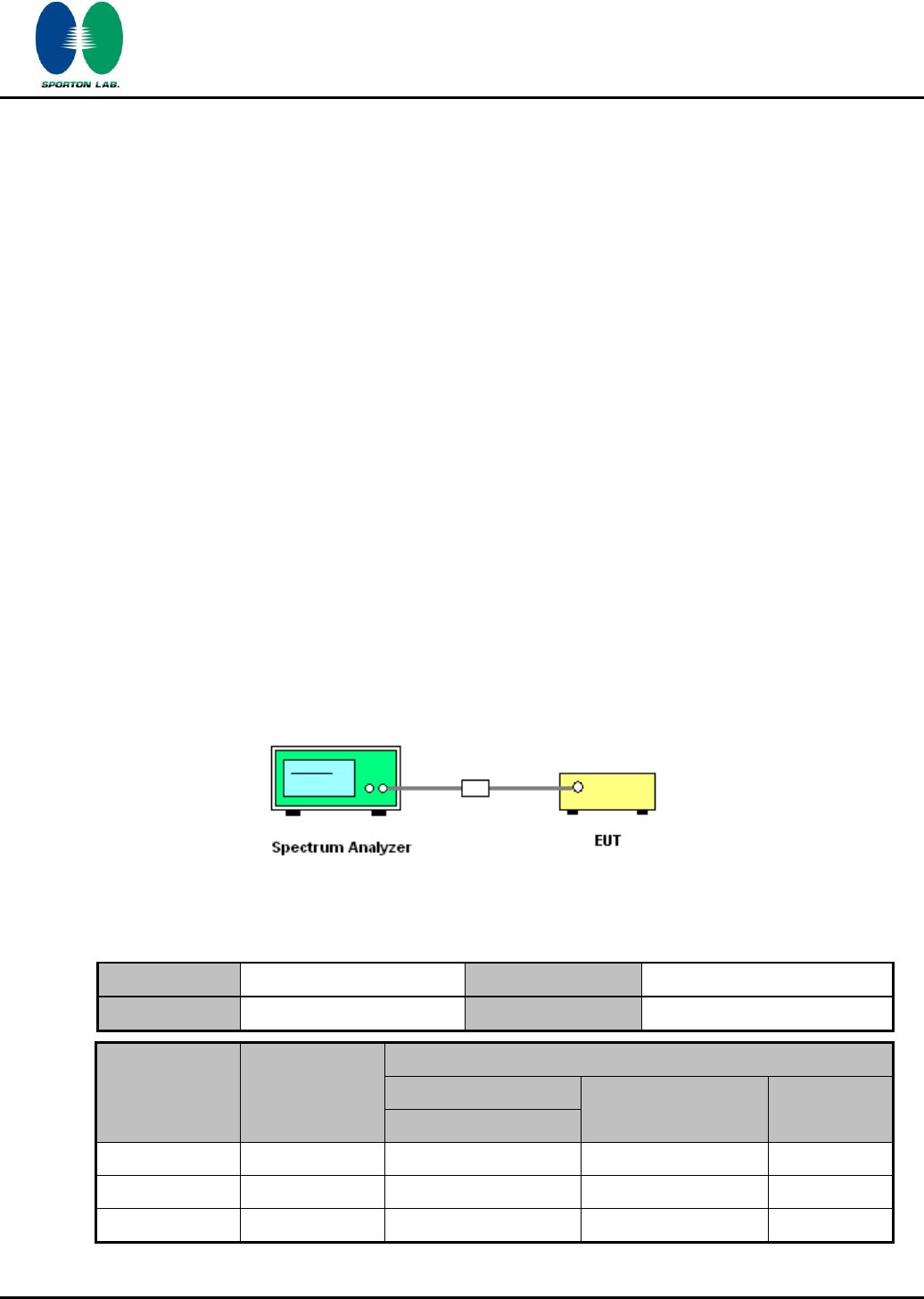
1. The testing follows FCC Public Notice DA 00-705 Measurement Guidelines.
2. The RF output of EUT was connected to the spectrum analyzer by a low loss cable.
3.5.4 Test Setup
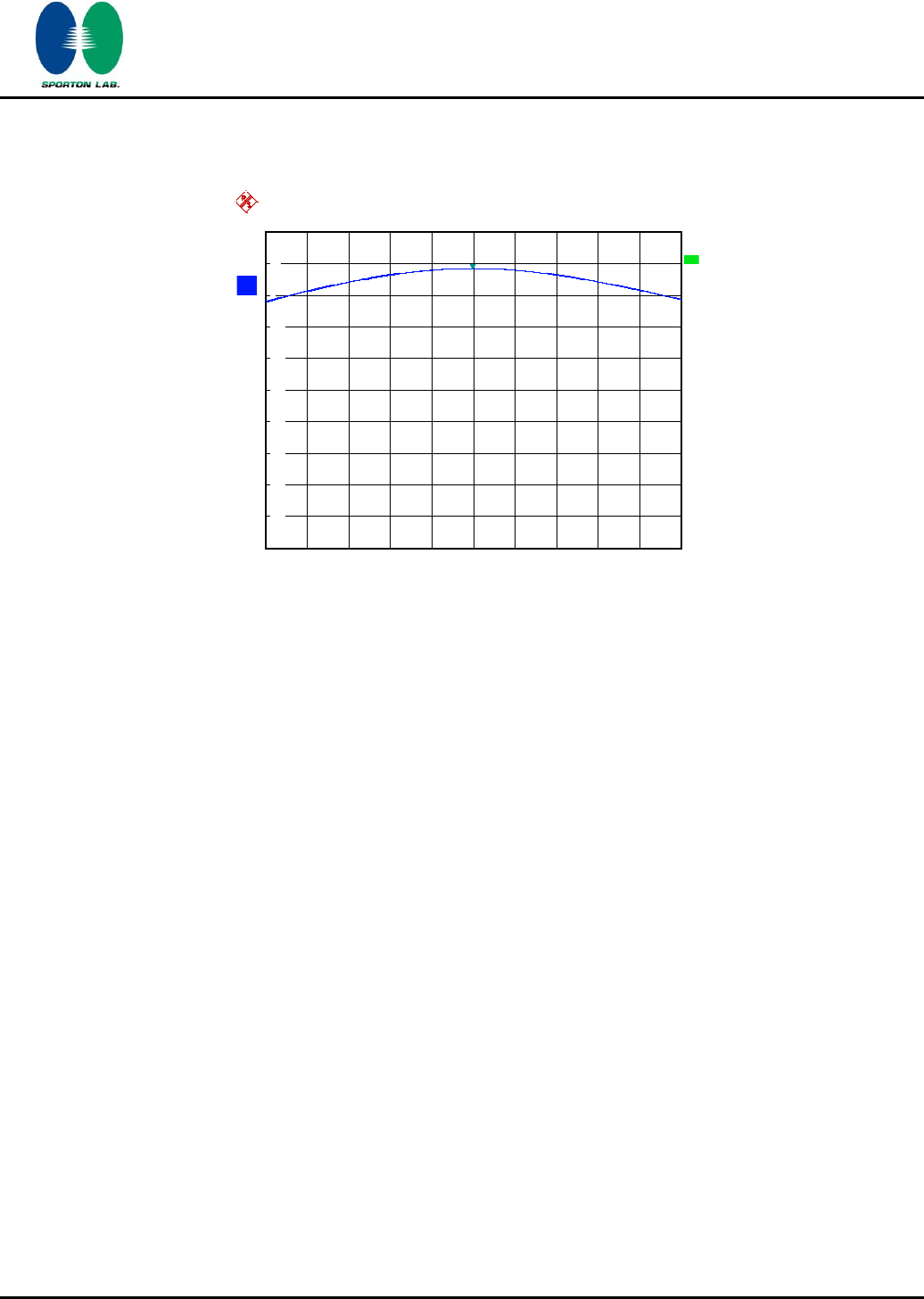
3.5.5 Test Result of Peak Output Power
Test Mode :
Mode 7, 8, 9
Temperature :
22~24℃
Test Engineer :
Reece Li
Relative Humidity :
53~57%
Channel
Frequency
(MHz)
RF Power (dBm)
8-DPSK
Max. Limits
(dBm)
Pass/Fail
3 Mbps
00
2402
8.32
20.97
Pass
39
2441
8.67
20.97
Pass
78
2480
8.45
20.97
Pass

SPORTON INTERNATIONAL INC.
Page Number
:
32 of 65
TEL : 886-3-327-3456
Report Issued Date
:
Feb. 14, 2012
FAX : 886-3-328-4978
Report Version
:
Rev. 02
FCC ID : L6AREF30LW
FCC RF Test Report
Report No. : FR1O2838A
Peak Output Power Plot on Channel 00
Peak Output Power Plot on Channel 39
A
Att
20 dB
*
*
Ref
20 dBm
Offset
20.2 dB
LVL
Center
2.402 GHz
Span
6 MHz
600 kHz/
*
3DB
RBW
3 MHz
SWT
500 ms
*
VBW
3 MHz
*
1 PK
MAXH
-80
-70
-60
-50
-40
-30
-20
-10
0
10
20
1
Marker 1 [T1 ]
8.32 dBm
2.402000000 GHz
Date: 29.NOV.2011 20:30:06
A
Att
20 dB
*
*
Ref
20 dBm
Offset
20.2 dB
LVL
Center
2.441 GHz
Span
6 MHz
600 kHz/
*
3DB
RBW
3 MHz
SWT
500 ms
*
VBW
3 MHz
*
1 PK
MAXH
-80
-70
-60
-50
-40
-30
-20
-10
0
10
20
1
Marker 1 [T1 ]
8.67 dBm
2.441000000 GHz
Date: 29.NOV.2011 20:31:20
720510
720510
SPORTON INTERNATIONAL INC.
Page Number
:
33 of 65
TEL : 886-3-327-3456
Report Issued Date
:
Feb. 14, 2012
FAX : 886-3-328-4978
Report Version
:
Rev. 02
FCC ID : L6AREF30LW
FCC RF Test Report
Report No. : FR1O2838A
Peak Output Power Plot on Channel 78
A
Att
20 dB
*
*
Ref
20 dBm
Offset
20.2 dB
LVL
Center
2.48 GHz
Span
6 MHz
600 kHz/
*
3DB
RBW
3 MHz
SWT
500 ms
*
VBW
3 MHz
*
1 PK
MAXH
-80
-70
-60
-50
-40
-30
-20
-10
0
10
20
1
Marker 1 [T1 ]
8.45 dBm
2.479988000 GHz
Date: 29.NOV.2011 20:32:34
720510

SPORTON INTERNATIONAL INC.
Page Number
:
34 of 65
TEL : 886-3-327-3456
Report Issued Date
:
Feb. 14, 2012
FAX : 886-3-328-4978
Report Version
:
Rev. 02
FCC ID : L6AREF30LW
FCC RF Test Report
Report No. : FR1O2838A
3.6 Band Edges Measurement
3.6.1 Limit of Band Edges
In any 100 KHz bandwidth outside the intentional radiation frequency band, the radio frequency
power shall be at least 20 dB below the highest level of the radiated power. In addition, radiated
emissions which fall in the restricted bands must also comply with the radiated emission limits.
3.6.2 Measuring Instruments
See list of measuring instruments of this test report.
3.6.3 Test Procedures
1. The testing follows the guidelines in ANSI C63.4-2003 and FCC Public Notice DA 00-705
Measurement Guidelines.
2. RF antenna conducted test: Set RBW = 300KHz, Video bandwidth (VBW) RBW. Band edge
emissions must be at least 20 dB down from the highest emission level within the authorized
band as measured with a 300k Hz RBW. Note: If the device complies with the use of power
option 2 the attenuation under this paragraph shall be 30 dB instead of 20 dB.
3. Radiated emission test: Applies to band edge emissions that fall in the restricted bands listed in
FCC Section 15.205. The maximum permitted average field strength is listed in FCC Section
15.209. A pre-amp is necessary for this measurement. For measurements above 1 GHz, set
RBW = 1MHz, VBW = 1MHz, Sweep: Auto for Peak; set RBW = 1MHz, VBW = 10 Hz, Sweep:
Auto for Average. If the emission is pulsed, modify the unit for continuous operation; use the
settings shown above, then correct the reading by subtracting the peak-average correction
factor, derived from the appropriate duty cycle calculation. See FCC Section 15.35(b) and (c).
4. In case the emission is fail due to the used RBW / VBW is too wide, marker-delta method of
FCC Public Notice DA 00-705 will be followed.
SPORTON INTERNATIONAL INC.
Page Number
:
36 of 65
TEL : 886-3-327-3456
Report Issued Date
:
Feb. 14, 2012
FAX : 886-3-328-4978
Report Version
:
Rev. 02
FCC ID : L6AREF30LW
FCC RF Test Report
Report No. : FR1O2838A
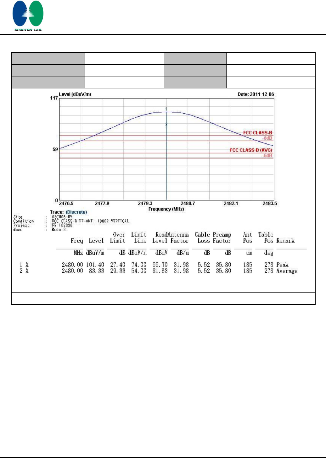
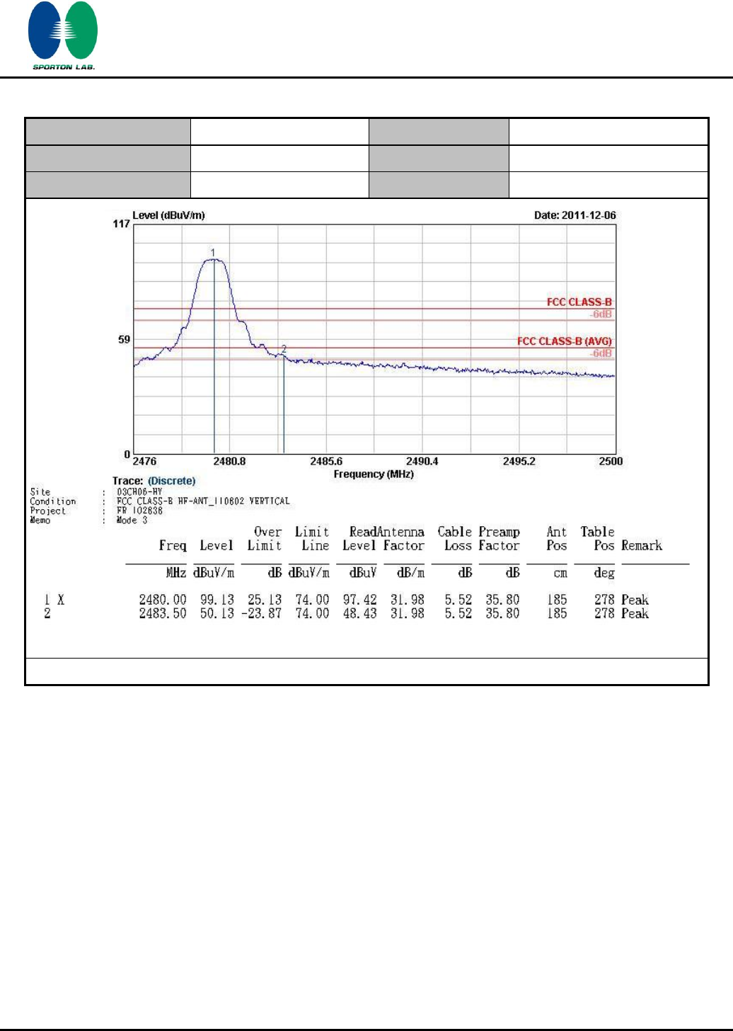
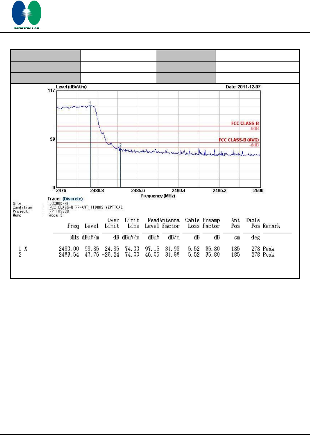
3.6.5 Test Result of Radiated Band Edges
Test Mode :
Mode 1
Temperature :
23~25°C
Test Channel :
00
Relative Humidity :
50~51%
Test Engineer :
Luke Chang
ANTENNA POLARITY : HORIZONTAL
Frequency
Level
Over
Limit
Read
Antenna
Cable
Preamp
Ant
Table
Remark
Limit
Line
Level
Factor
Loss
Factor
Pos
Pos
( MHz )
( dBuV/m )
( dB )
( dBuV/m )
(dBuV)
( dB )
( dB )
( dB )
( cm )
( deg )
2385.05
56.8
-17.2
74
55.38
31.88
5.4
35.86
100
123
Peak
2385.05
34.08
-19.92
54
32.66
31.88
5.4
35.86
100
123
Average
ANTENNA POLARITY : VERTICAL
Frequency
Level
Over
Limit
Read
Antenna
Cable
Preamp
Ant
Table
Remark
Limit
Line
Level
Factor
Loss
Factor
Pos
Pos
( MHz )
( dBuV/m )
( dB )
( dBuV/m )
(dBuV)
( dB )
( dB )
( dB )
( cm )
( deg )
2385.62
53.33
-20.67
74
51.89
31.9
5.4
35.86
100
278
Peak
2385.62
33.15
-20.85
54
31.71
31.9
5.4
35.86
100
278
Average
SPORTON INTERNATIONAL INC.
Page Number
:
37 of 65
TEL : 886-3-327-3456
Report Issued Date
:
Feb. 14, 2012
FAX : 886-3-328-4978
Report Version
:
Rev. 02
FCC ID : L6AREF30LW
FCC RF Test Report
Report No. : FR1O2838A
Test Mode :
Mode 3
Temperature :
23~25°C
Test Channel :
78
Relative Humidity :
50~51%
Test Engineer :
Luke Chang
ANTENNA POLARITY : HORIZONTAL
Frequency
Level
Over
Limit
Read
Antenna
Cable
Preamp
Ant
Table
Remark
Limit
Line
Level
Factor
Loss
Factor
Pos
Pos
( MHz )
( dBuV/m )
( dB )
( dBuV/m )
(dBuV)
( dB )
( dB )
( dB )
( cm )
( deg )
2483.5
68.48
-5.52
74
66.78
31.98
5.52
35.8
100
132
Peak
2483.5
36.14
-17.86
54
34.44
31.98
5.52
35.8
100
132
Average
Summary results of marker-delta method:
Test mode
Maximum field
strength of the
fundamental emission
(dBμV/m)
Delta
Result
(dB)
Average
Result
(dBμV/m)
Average
Limit
(dBμV/m)
Margin
(dB)
Result
Single Carrier Mode
85.89
49.75
36.14
54
-17.86
Pass
Hopping Mode
85.89
51.84
34.05
54
-19.95
Pass
Note: Average result = Maximum field strength – Delta result
ANTENNA POLARITY : VERTICAL
Frequency
Level
Over
Limit
Read
Antenna
Cable
Preamp
Ant
Table
Remark
Limit
Line
Level
Factor
Loss
Factor
Pos
Pos
( MHz )
( dBuV/m )
( dB )
( dBuV/m )
(dBuV)
( dB )
( dB )
( dB )
( cm )
( deg )
2483.5
65.18
-8.82
74
63.48
31.98
5.52
35.8
185
278
Peak
2483.5
34.33
-19.67
54
32.63
31.98
5.52
35.8
185
278
Average
Summary results of marker-delta method:
Test mode
Maximum field
strength of the
fundamental emission
(dBμV/m)
Delta
Result
(dB)
Average
Result
(dBμV/m)
Average
Limit
(dBμV/m)
Margin
(dB)
Result
Single Carrier Mode
83.33
49
34.33
54
-19.67
Pass
Hopping Mode
83.33
51.09
32.24
54
-21.76
Pass
Note : Average result = Maximum field strength – Delta result
SPORTON INTERNATIONAL INC.
Page Number
:
38 of 65
TEL : 886-3-327-3456
Report Issued Date
:
Feb. 14, 2012
FAX : 886-3-328-4978
Report Version
:
Rev. 02
FCC ID : L6AREF30LW
FCC RF Test Report
Report No. : FR1O2838A
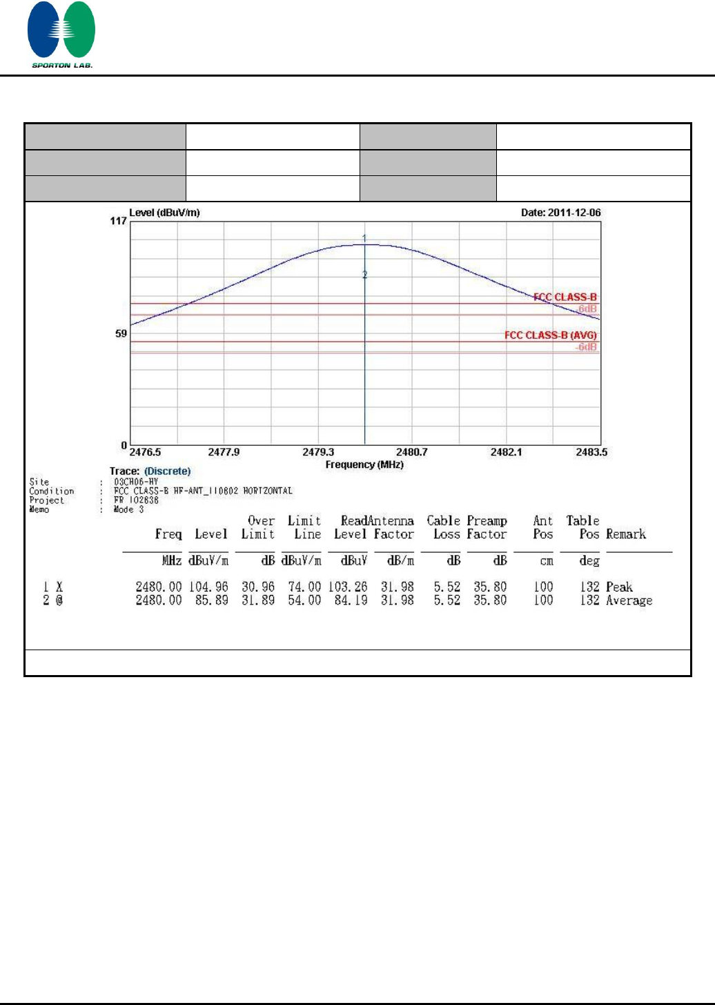
Test Mode :
Mode 3
Temperature :
23~25°C
Test Channel :
78
Relative Humidity :
50~51%
Test Engineer :
Luke Chang
Polarization :
Horizontal
* Maximum field strength of the fundamental emission

SPORTON INTERNATIONAL INC.
Page Number
:
39 of 65
TEL : 886-3-327-3456
Report Issued Date
:
Feb. 14, 2012
FAX : 886-3-328-4978
Report Version
:
Rev. 02
FCC ID : L6AREF30LW
FCC RF Test Report
Report No. : FR1O2838A
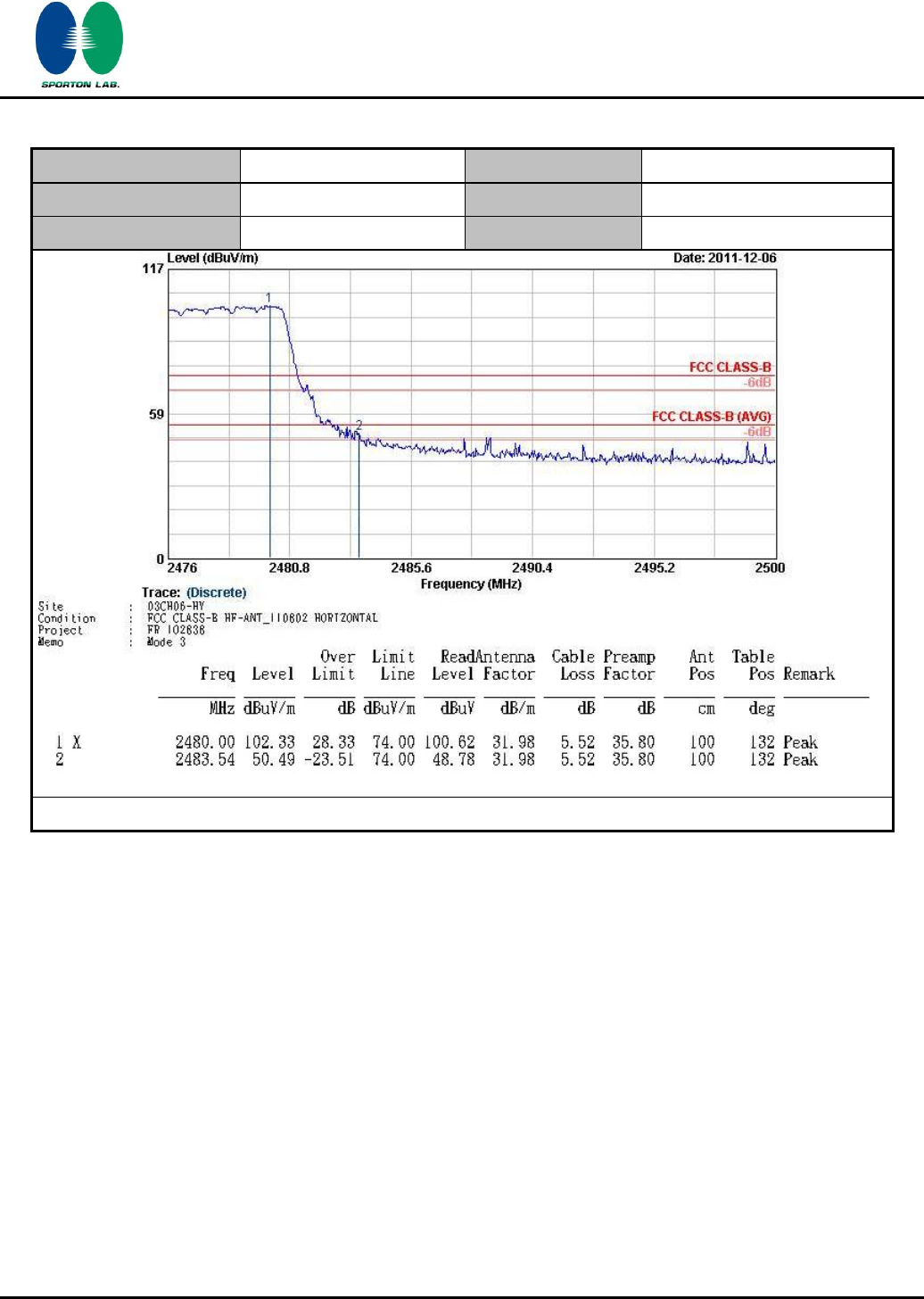
Test Mode :
Mode 3
Temperature :
23~25°C
Test Channel :
78
Relative Humidity :
50~51%
Test Engineer :
Luke Chang
Polarization :
Horizontal
* Marker-Delta Method (RBW/VBW=100KHz): 49.75 dB , single carrier Mode
SPORTON INTERNATIONAL INC.
Page Number
:
40 of 65
TEL : 886-3-327-3456
Report Issued Date
:
Feb. 14, 2012
FAX : 886-3-328-4978
Report Version
:
Rev. 02
FCC ID : L6AREF30LW
FCC RF Test Report
Report No. : FR1O2838A
Test Mode :
Mode 3
Temperature :
23~25°C
Test Channel :
78
Relative Humidity :
50~51%
Test Engineer :
Luke Chang
Polarization :
Horizontal
* Marker-Delta Method (RBW/VBW=100KHz): 51.84 dB , Hopping Mode
SPORTON INTERNATIONAL INC.
Page Number
:
41 of 65
TEL : 886-3-327-3456
Report Issued Date
:
Feb. 14, 2012
FAX : 886-3-328-4978
Report Version
:
Rev. 02
FCC ID : L6AREF30LW
FCC RF Test Report
Report No. : FR1O2838A
Test Mode :
Mode 3
Temperature :
23~25°C
Test Channel :
78
Relative Humidity :
50~51%
Test Engineer :
Luke Chang
Polarization :
Vertical
* Maximum field strength of the fundamental emission
SPORTON INTERNATIONAL INC.
Page Number
:
42 of 65
TEL : 886-3-327-3456
Report Issued Date
:
Feb. 14, 2012
FAX : 886-3-328-4978
Report Version
:
Rev. 02
FCC ID : L6AREF30LW
FCC RF Test Report
Report No. : FR1O2838A
Test Mode :
Mode 3
Temperature :
23~25°C
Test Channel :
78
Relative Humidity :
50~51%
Test Engineer :
Luke Chang
Polarization :
Vertical
* Marker-Delta Method (RBW/VBW=100KHz): 49.00 dB , single carrier Mode
SPORTON INTERNATIONAL INC.
Page Number
:
43 of 65
TEL : 886-3-327-3456
Report Issued Date
:
Feb. 14, 2012
FAX : 886-3-328-4978
Report Version
:
Rev. 02
FCC ID : L6AREF30LW
FCC RF Test Report
Report No. : FR1O2838A
Test Mode :
Mode 3
Temperature :
23~25°C
Test Channel :
78
Relative Humidity :
50~51%
Test Engineer :
Luke Chang
Polarization :
Vertical
* Marker-Delta Method (RBW/VBW=100KHz): 51.09 dB , Hopping Mode
SPORTON INTERNATIONAL INC.
Page Number
:
44 of 65
TEL : 886-3-327-3456
Report Issued Date
:
Feb. 14, 2012
FAX : 886-3-328-4978
Report Version
:
Rev. 02
FCC ID : L6AREF30LW
FCC RF Test Report
Report No. : FR1O2838A
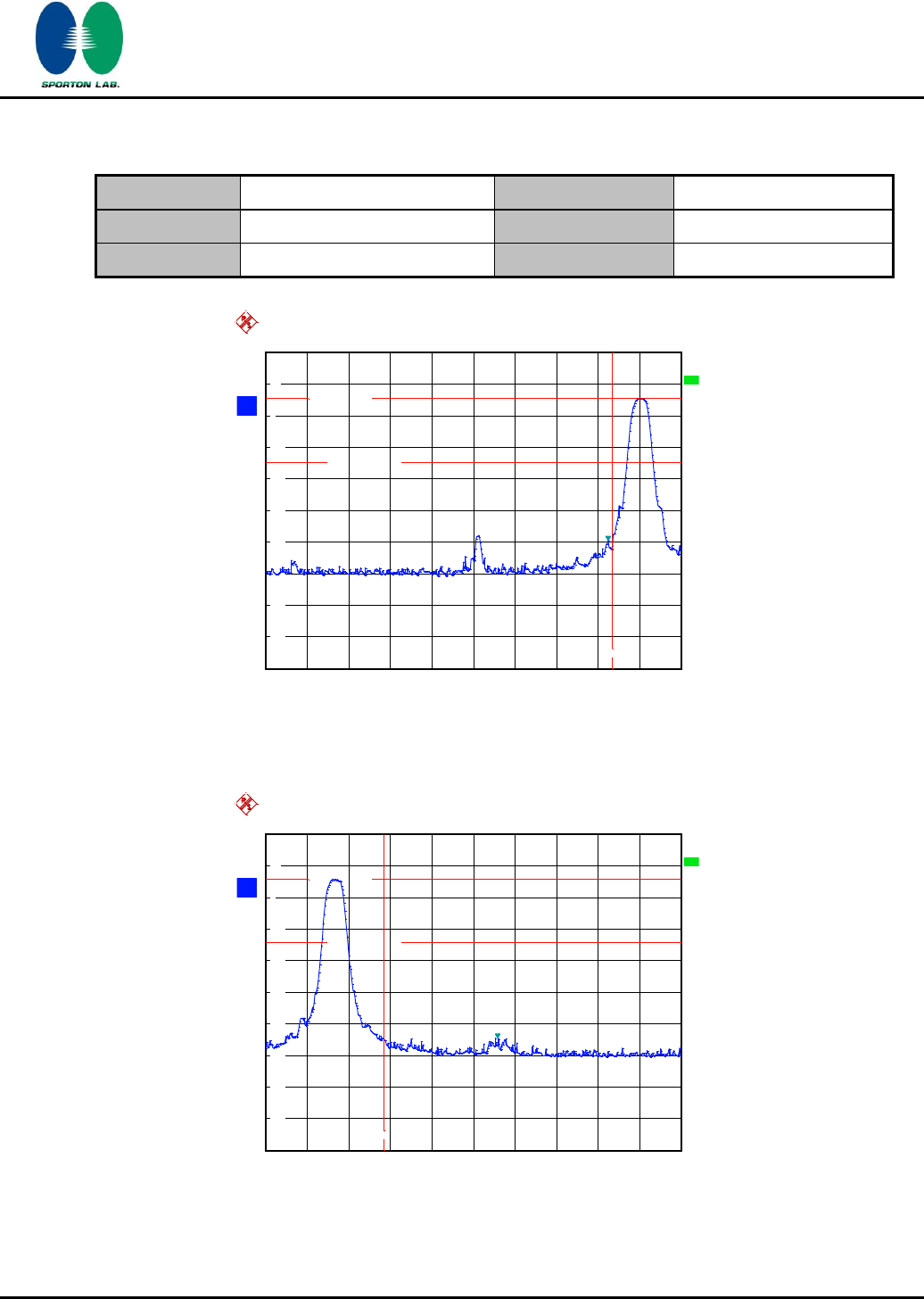
3.6.6 Test Result of Conducted Band Edges
Test Mode :
Mode 7 and 9
Temperature :
22~24℃
Test Channel :
00 and 78
Relative Humidity :
53~57%
Test Engineer :
Reece Li
Low Band Edge Plot on Channel 00
High Band Edge Plot on Channel 78
A
Offset
20.2 dB
LVL
Ref
20 dBm
Att
20 dB
*
3 MHz/
Start
2.375 GHz
Stop
2.405 GHz
3DB
RBW
300 kHz
SWT
2.5 ms
*
VBW
300 kHz
*
1 PK
MAXH
-80
-70
-60
-50
-40
-30
-20
-10
0
10
20
1
Marker 1 [T1 ]
-39.41 dBm
2.399720000 GHz
D1 5.33 dBm
D2 -14.67 dBm
F1
Date: 29.NOV.2011 21:57:16
A
Offset
20.2 dB
LVL
Ref
20 dBm
Att
20 dB
*
3 MHz/
Start
2.475 GHz
Stop
2.505 GHz
3DB
RBW
300 kHz
SWT
2.5 ms
*
VBW
300 kHz
*
1 PK
MAXH
-80
-70
-60
-50
-40
-30
-20
-10
0
10
20
1
Marker 1 [T1 ]
-44.37 dBm
2.491740000 GHz
D1 5.67 dBm
D2 -14.33 dBm
F1
Date: 29.NOV.2011 21:58:20
720510
720510
SPORTON INTERNATIONAL INC.
Page Number
:
45 of 65
TEL : 886-3-327-3456
Report Issued Date
:
Feb. 14, 2012
FAX : 886-3-328-4978
Report Version
:
Rev. 02
FCC ID : L6AREF30LW
FCC RF Test Report
Report No. : FR1O2838A
3.7 Spurious Emission Measurement
3.7.1 Limit of Spurious Emission Measurement
All harmonics/spurious must be at least 20 dB down from the highest emission level within the
authorized band.
3.7.2 Measuring Instruments
See list of measuring instruments of this test report.
3.7.3 Test Procedure
1. The transmitter output was connected to the spectrum analyzer via a low lose cable.
2. Set RBW = 100 KHz, Video bandwidth (VBW) ≥ RBW, scan up through 10th harmonic. All
harmonics / spurs must be at least 20 dB down from the highest emission level within the
authorized band as measured with a 100 KHz RBW.
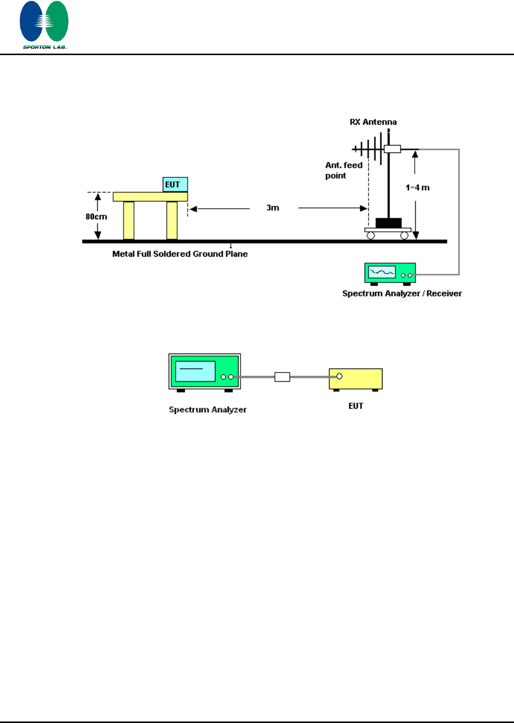
3.7.4 Test Setup
SPORTON INTERNATIONAL INC.
Page Number
:
46 of 65
TEL : 886-3-327-3456
Report Issued Date
:
Feb. 14, 2012
FAX : 886-3-328-4978
Report Version
:
Rev. 02
FCC ID : L6AREF30LW
FCC RF Test Report
Report No. : FR1O2838A
3.7.5 Test Result
Test Mode :
Mode 7
Temperature :
22~24℃
Test Channel :
00
Relative Humidity :
53~57%
Test Engineer :
Reece Li
Conducted Spurious Emission Plot between 30MHz ~ 3 GHz
Conducted Spurious Emission Plot between 3 GHz ~ 25 GHz
A
Att
20 dB
*
Ref
20 dBm
Offset
20.2 dB
LVL
Start
30 MHz
Stop
3 GHz
297 MHz/
*
*
3DB
RBW
100 kHz
VBW
300 kHz
SWT
300 ms
1 PK
VIEW
-80
-70
-60
-50
-40
-30
-20
-10
0
10
20
1
Marker 1 [T1 ]
-45.31 dBm
2.376300000 GHz
D1 -16.12 dBm
Date: 29.NOV.2011 22:10:17
Ref
20 dBm
Att
20 dB
*
*
Offset
20.6 dB
A
LVL
RBW
100 kHz
VBW
300 kHz
SWT
2.2 s
*
Start
3 GHz
Stop
25 GHz
2.2 GHz/
3DB
1 PK
VIEW
-80
-70
-60
-50
-40
-30
-20
-10
0
10
20
1
Marker 1 [T1 ]
-33.43 dBm
21.304000000 GHz
D1 -16.12 dBm
Date: 29.NOV.2011 22:10:39
720510
720510
SPORTON INTERNATIONAL INC.
Page Number
:
47 of 65
TEL : 886-3-327-3456
Report Issued Date
:
Feb. 14, 2012
FAX : 886-3-328-4978
Report Version
:
Rev. 02
FCC ID : L6AREF30LW
FCC RF Test Report
Report No. : FR1O2838A
Test Mode :
Mode 8
Temperature :
22~24℃
Test Channel :
39
Relative Humidity :
53~57%
Test Engineer :
Reece Li
Conducted Spurious Emission Plot between 30MHz ~ 3 GHz
Conducted Spurious Emission Plot between 3 GHz ~ 25 GHz
A
Att
20 dB
*
Ref
20 dBm
Offset
20.2 dB
LVL
297 MHz/
Start
30 MHz
Stop
3 GHz
*
*
3DB
RBW
100 kHz
VBW
300 kHz
SWT
300 ms
1 PK
VIEW
-80
-70
-60
-50
-40
-30
-20
-10
0
10
20
1
Marker 1 [T1 ]
-45.50 dBm
2.376300000 GHz
D1 -15.36 dBm
Date: 29.NOV.2011 22:09:24
Ref
20 dBm
Att
20 dB
*
*
Offset
20.6 dB
A
LVL
RBW
100 kHz
VBW
300 kHz
SWT
2.2 s
*
Start
3 GHz
Stop
25 GHz
2.2 GHz/
3DB
1 PK
VIEW
-80
-70
-60
-50
-40
-30
-20
-10
0
10
20
1
Marker 1 [T1 ]
-33.21 dBm
21.920000000 GHz
D1 -15.36 dBm
Date: 29.NOV.2011 22:09:46
720510
720510
SPORTON INTERNATIONAL INC.
Page Number
:
48 of 65
TEL : 886-3-327-3456
Report Issued Date
:
Feb. 14, 2012
FAX : 886-3-328-4978
Report Version
:
Rev. 02
FCC ID : L6AREF30LW
FCC RF Test Report
Report No. : FR1O2838A
Test Mode :
Mode 9
Temperature :
22~24℃
Test Channel :
78
Relative Humidity :
53~57%
Test Engineer :
Reece Li
Conducted Spurious Emission Plot between 30MHz ~ 3 GHz
Conducted Spurious Emission Plot between 3 GHz ~ 25 GHz
A
Att
20 dB
*
Ref
20 dBm
Offset
20.2 dB
LVL
Start
30 MHz
Stop
3 GHz
297 MHz/
*
*
3DB
RBW
100 kHz
VBW
300 kHz
SWT
300 ms
1 PK
VIEW
-80
-70
-60
-50
-40
-30
-20
-10
0
10
20
1
Marker 1 [T1 ]
-42.83 dBm
2.376300000 GHz
D1 -14.31 dBm
Date: 29.NOV.2011 22:11:08
Ref
20 dBm
Att
20 dB
*
*
Offset
20.6 dB
A
LVL
RBW
100 kHz
VBW
300 kHz
SWT
2.2 s
*
Start
3 GHz
Stop
25 GHz
2.2 GHz/
3DB
1 PK
VIEW
-80
-70
-60
-50
-40
-30
-20
-10
0
10
20
1
Marker 1 [T1 ]
-32.12 dBm
21.876000000 GHz
D1 -14.31 dBm
Date: 29.NOV.2011 22:11:29
720510
720510
SPORTON INTERNATIONAL INC.
Page Number
:
49 of 65
TEL : 886-3-327-3456
Report Issued Date
:
Feb. 14, 2012
FAX : 886-3-328-4978
Report Version
:
Rev. 02
FCC ID : L6AREF30LW
FCC RF Test Report
Report No. : FR1O2838A
3.8 AC Conducted Emission Measurement
3.8.1 Limit of AC Conducted Emission
For equipment that is designed to be connected to the public utility (AC) power line, the radio
frequency voltage that is conducted back onto the AC power line on any frequency or frequencies
within the band 150 KHz to 30 MHz shall not exceed the limits in the following table.
Frequency of emission (MHz)
Conducted limit (dBuV)
Quasi-peak
Average
0.15-0.5
66 to 56*
56 to 46*
0.5-5
56
46
5-30
60
50
*Decreases with the logarithm of the frequency.
3.8.2 Measuring Instruments
See list of measuring instruments of this test report.
3.8.3 Test Procedures
1. Please follow the guidelines in ANSI C63.4-2003.
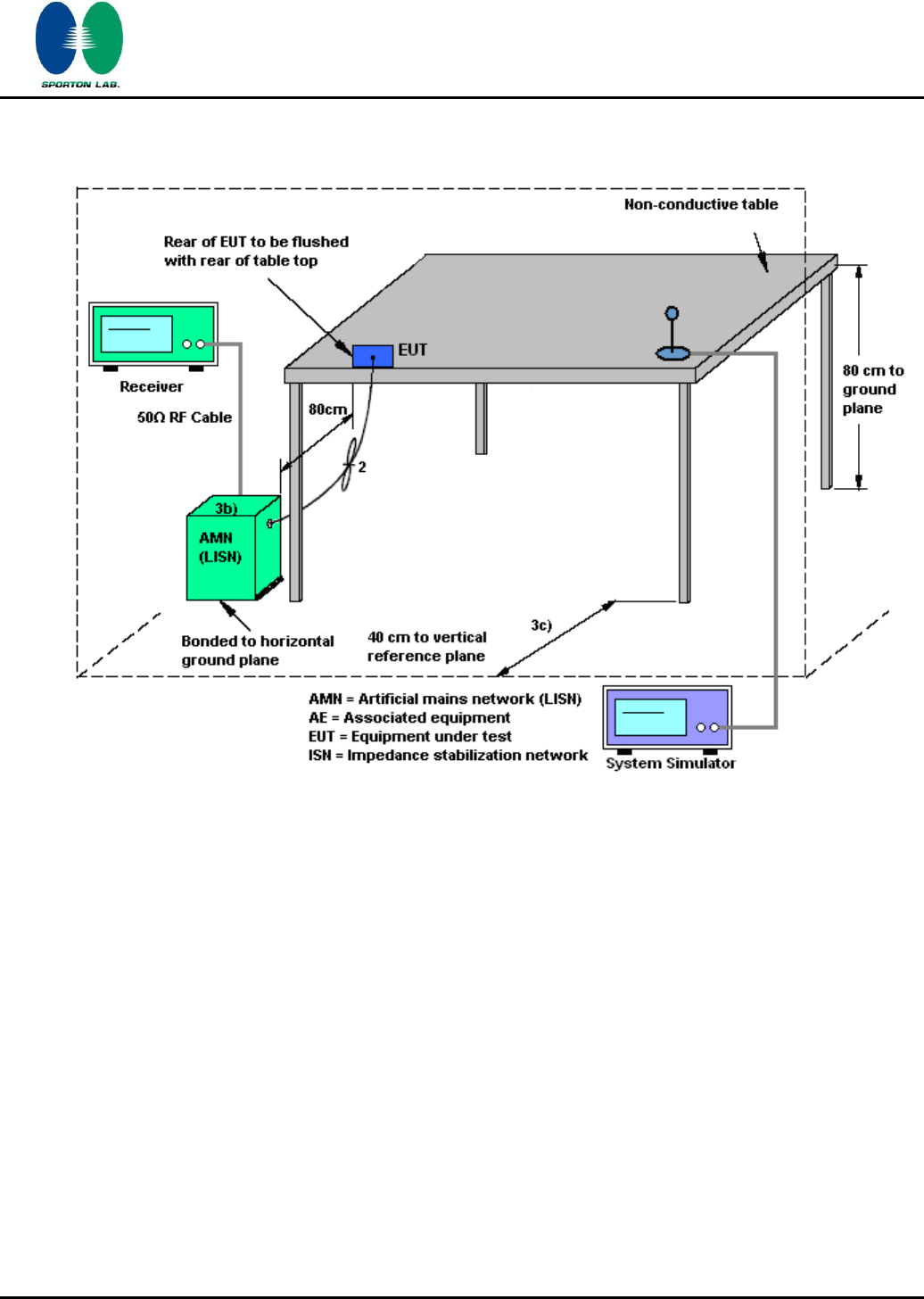
2. The EUT was placed 0.4 meter from the conducting wall of the shielding room was kept at least
80 centimeters from any other grounded conducting surface.
3. Connect EUT to the power mains through a line impedance stabilization network (LISN).
4. All the support units are connecting to the other LISN.
5. The LISN provides 50 ohm coupling impedance for the measuring instrument.
6. The FCC states that a 50 ohm, 50 microhenry LISN should be used.
7. Both sides of AC line were checked for maximum conducted interference.
8. The frequency range from 150 KHz to 30 MHz was searched.
9. Set the test-receiver system to Peak Detect Function and specified bandwidth with Maximum
Hold Mode.
SPORTON INTERNATIONAL INC.
Page Number
:
51 of 65
TEL : 886-3-327-3456
Report Issued Date
:
Feb. 14, 2012
FAX : 886-3-328-4978
Report Version
:
Rev. 02
FCC ID : L6AREF30LW
FCC RF Test Report
Report No. : FR1O2838A
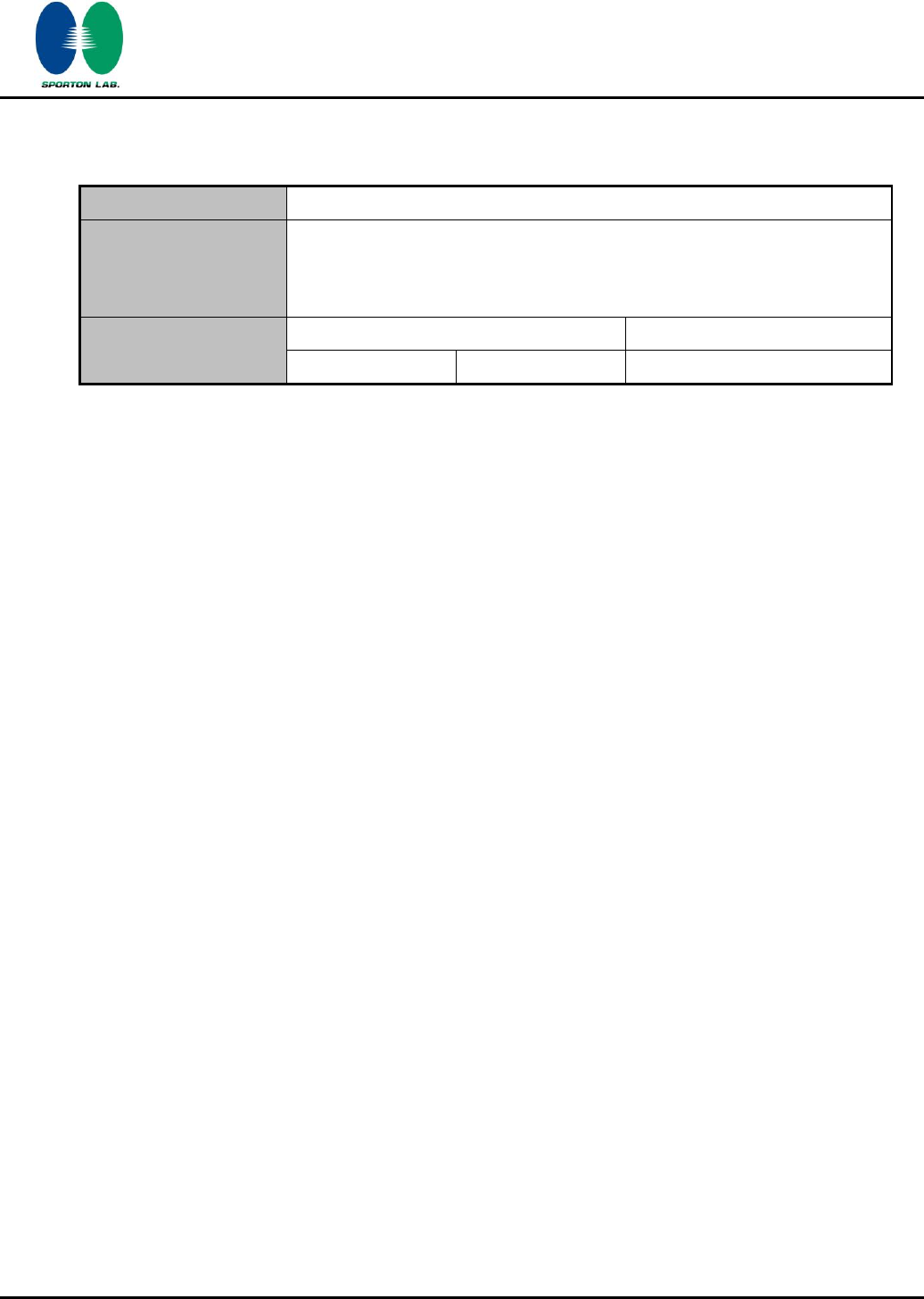
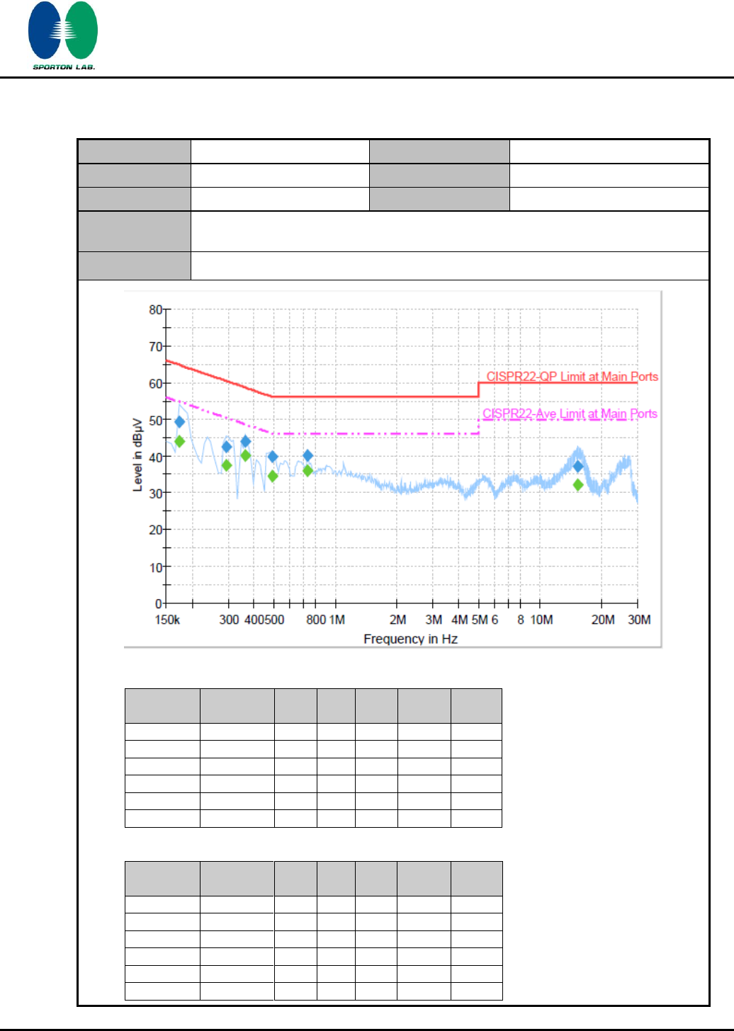
3.8.5 Test Result of AC Conducted Emission
Test Mode :
Mode 1
Temperature :
20~23℃
Test Engineer :
Aslen Chiu
Relative Humidity :
42~45%
Test Voltage :
120Vac / 60Hz
Phase :
Line
Function Type :
CDMA 850 Idle + Bluetooth Link + WLAN (2.4G) Link + Adapter 3 + Battery 1 + H
Pattern + Earphone
Remark :
All emissions not reported here are more than 10 dB below the prescribed limit.
Final Result 1
Frequency
(MHz)
QuasiPeak
(dBµV)
Filter
Line
Corr.
(dB)
Margin
(dB)
Limit
(dBµV)
0.174000
49.3
Off
L1
19.4
15.5
64.8
0.294000
42.5
Off
L1
19.4
17.9
60.4
0.366000
44.1
Off
L1
19.4
14.5
58.6
0.494000
39.8
Off
L1
19.4
16.3
56.1
0.734000
40.2
Off
L1
19.4
15.8
56.0
15.238000
37.3
Off
L1
19.7
22.7
60.0
Final Result 2
Frequency
(MHz)
Average
(dBµV)
Filter
Line
Corr.
(dB)
Margin
(dB)
Limit
(dBµV)
0.174000
44.1
Off
L1
19.4
10.7
54.8
0.294000
37.6
Off
L1
19.4
12.8
50.4
0.366000
40.1
Off
L1
19.4
8.5
48.6
0.494000
34.4
Off
L1
19.4
11.7
46.1
0.734000
36.0
Off
L1
19.4
10.0
46.0
15.238000
32.3
Off
L1
19.7
17.7
50.0
SPORTON INTERNATIONAL INC.
Page Number
:
52 of 65
TEL : 886-3-327-3456
Report Issued Date
:
Feb. 14, 2012
FAX : 886-3-328-4978
Report Version
:
Rev. 02
FCC ID : L6AREF30LW
FCC RF Test Report
Report No. : FR1O2838A
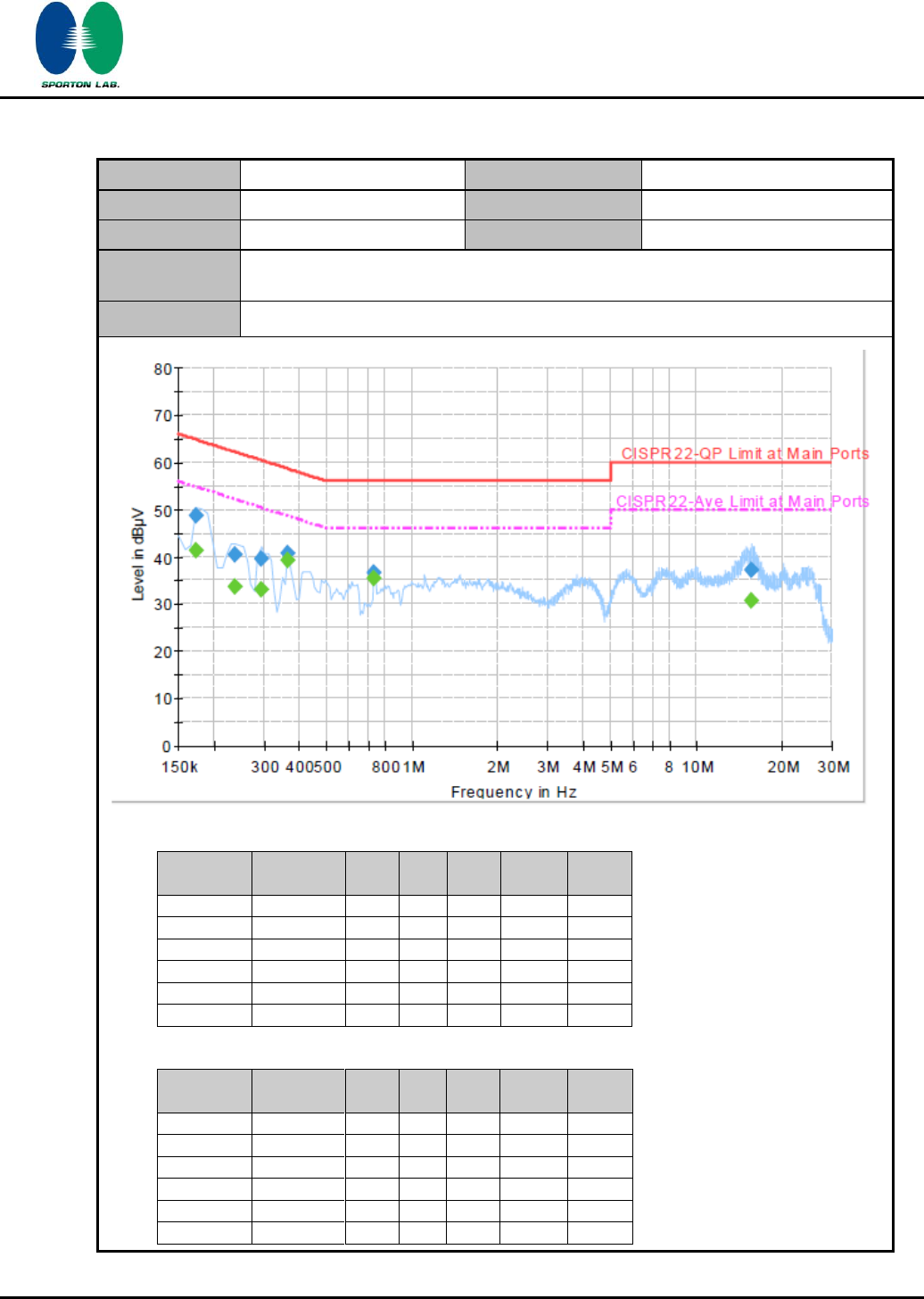
Test Mode :
Mode 1
Temperature :
20~23℃
Test Engineer :
Aslen Chiu
Relative Humidity :
42~45%
Test Voltage :
120Vac / 60Hz
Phase :
Neutral
Function Type :
CDMA 850 Idle + Bluetooth Link + WLAN (2.4G) Link + Adapter 3 + Battery 1 + H
Pattern + Earphone
Remark :
All emissions not reported here are more than 10 dB below the prescribed limit.
Final Result 1
Frequency
(MHz)
QuasiPeak
(dBµV)
Filter
Line
Corr.
(dB)
Margin
(dB)
Limit
(dBµV)
0.174000
48.7
Off
N
19.4
16.1
64.8
0.238000
40.4
Off
N
19.4
21.8
62.2
0.294000
39.6
Off
N
19.4
20.8
60.4
0.366000
40.7
Off
N
19.4
17.9
58.6
0.734000
36.7
Off
N
19.4
19.3
56.0
15.566000
37.3
Off
N
19.7
22.7
60.0
Final Result 2
Frequency
(MHz)
Average
(dBµV)
Filter
Line
Corr.
(dB)
Margin
(dB)
Limit
(dBµV)
0.174000
41.4
Off
N
19.4
13.4
54.8
0.238000
33.6
Off
N
19.4
18.6
52.2
0.294000
33.1
Off
N
19.4
17.3
50.4
0.366000
39.2
Off
N
19.4
9.4
48.6
0.734000
35.4
Off
N
19.4
10.6
46.0
15.566000
30.6
Off
N
19.7
19.4
50.0
SPORTON INTERNATIONAL INC.
Page Number
:
53 of 65
TEL : 886-3-327-3456
Report Issued Date
:
Feb. 14, 2012
FAX : 886-3-328-4978
Report Version
:
Rev. 02
FCC ID : L6AREF30LW
FCC RF Test Report
Report No. : FR1O2838A
3.9 Radiated Emission Measurement
3.9.1 Limit of Radiated Emission
In any 100 KHz bandwidth outside the intentional radiator frequency band, all harmonics/spurious
must be at least 20 dB below the highest emission level within the authorized band. In addition,
radiated emissions which fall in the restricted bands must also comply with the FCC section 15.209
limits as below.
Frequency
(MHz)
Field Strength
(microvolts/meter)
Measurement Distance
(meters)
0.009 – 0.490
2400/F(KHz)
300
0.490 – 1.705
24000/F(KHz)
30
1.705 – 30.0
30
30
30 – 88
100
3
88 – 216
150
3
216 - 960
200
3
Above 960
500
3
3.9.2 Measuring Instruments
See list of measuring instruments of this test report.
3.9.3 Test Procedures
1. The testing follows the guidelines in FCC Public Notice DA 00-705 Measurement Guidelines.
2. Use the following spectrum analyzer settings:
(1) Span = wide enough to fully capture the emission being measured; RBW = 1 MHz for f 1
GHz, 100 KHz for f < 1 GHz; VBW RBW; Sweep = auto; Detector function = peak; Trace
= max hold.
(2) Above 18 GHz shall be extrapolated to the specified distance using an extrapolation factor
of 20 dB/decade from 3m to 1m.
Distance extrapolation factor = 20 log (specific distance [3m] / test distance [1m]) (dB)
3. Follow the guidelines in ANSI C63.4-2003 with respect to maximizing the emission by rotating
the EUT, measuring the emission for three EUT orthogonal planes, and adjusting the
measurement antenna height and polarization. A pre-amp and a high pass filter are used for
this test in order to get the good signal level.
4. Measured average value for the peak value is greater than 54 dBuv/m
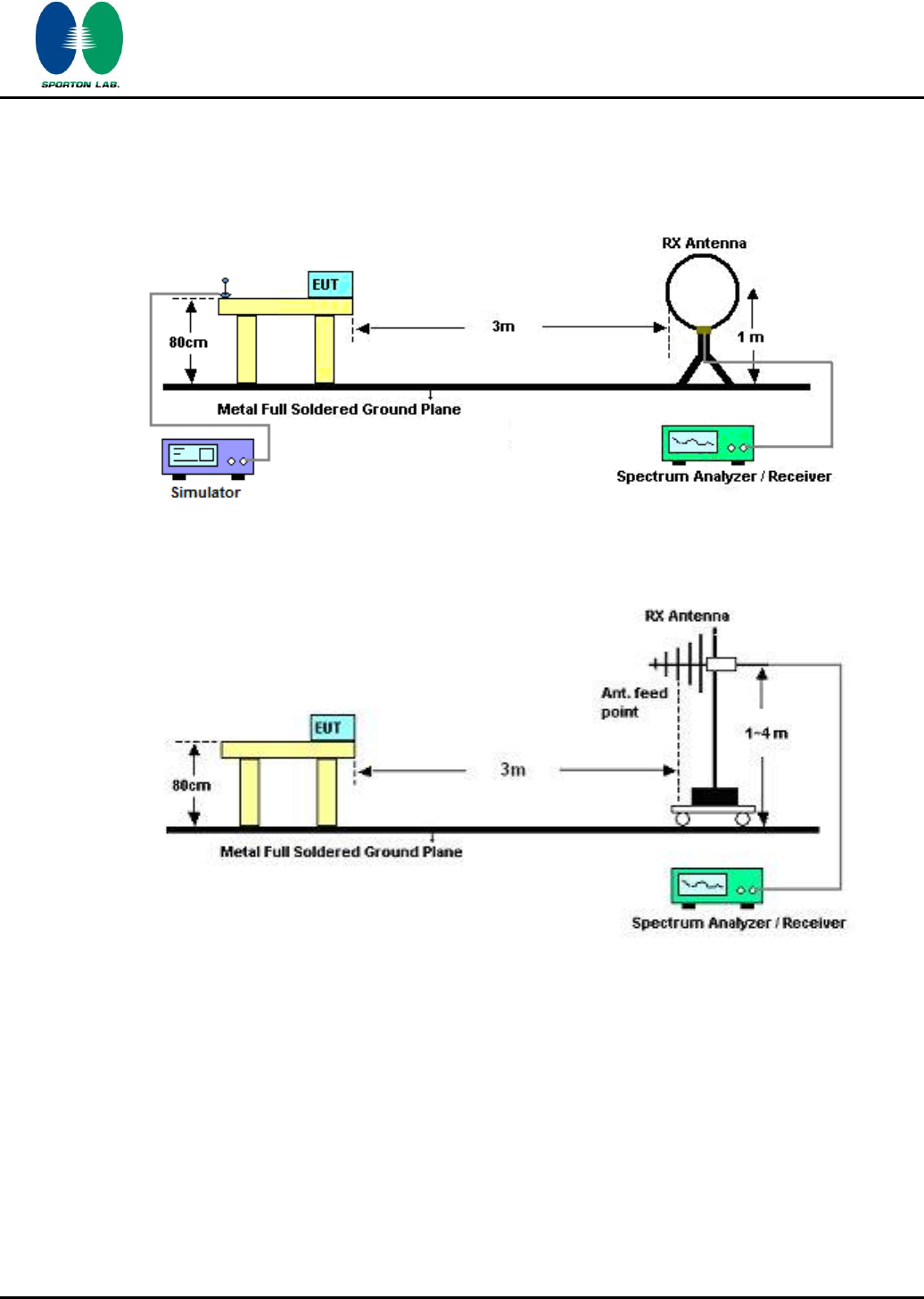
SPORTON INTERNATIONAL INC.
Page Number
:
54 of 65
TEL : 886-3-327-3456
Report Issued Date
:
Feb. 14, 2012
FAX : 886-3-328-4978
Report Version
:
Rev. 02
FCC ID : L6AREF30LW
FCC RF Test Report
Report No. : FR1O2838A
3.9.4 Test Setup
For radiated emissions below 30MHz
For radiated emissions from 30MHz to 1GHz
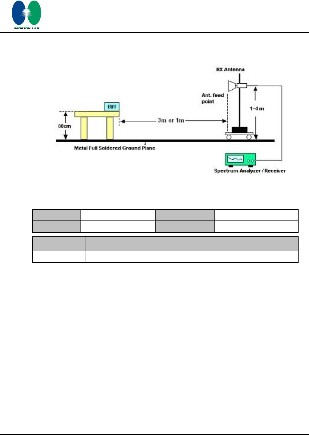
SPORTON INTERNATIONAL INC.
Page Number
:
55 of 65
TEL : 886-3-327-3456
Report Issued Date
:
Feb. 14, 2012
FAX : 886-3-328-4978
Report Version
:
Rev. 02
FCC ID : L6AREF30LW
FCC RF Test Report
Report No. : FR1O2838A
For radiated emissions above 1GHz
3.9.5 Test Results of Radiated Emissions (9 KHz ~ 30 MHz)
Test Engineer :
Luke Chang
Temperature :
23~25°C
Relative Humidity :
50~51%
Frequency
Level
Over Limit
Limit Line
Remark
(MHz)
(dBuV)
(dB)
(dBuV)
-
-
-
-
See Note
Note:
The amplitude of spurious emissions that are attenuated by more than 20dB below the permissible
value has no need to be reported.
Distance extrapolation factor = 40 log (specific distance / test distance) (dB);
Limit line = specific limits (dBuV) + distance extrapolation factor.
SPORTON INTERNATIONAL INC.
Page Number
:
56 of 65
TEL : 886-3-327-3456
Report Issued Date
:
Feb. 14, 2012
FAX : 886-3-328-4978
Report Version
:
Rev. 02
FCC ID : L6AREF30LW
FCC RF Test Report
Report No. : FR1O2838A
3.9.6 Test Result of Radiated Emission (30 MHz ~ 10th Harmonic)
Test Mode :
Mode 1
Temperature :
23~25°C
Test Channel :
00
Relative Humidity :
50~51%
Test Engineer :
Luke Chang
Polarization :
Horizontal
Remark :
2402 MHz is Fundamental Signals which can be ignored.
Frequency
Level
Over
Limit
Read
Antenna
Cable
Preamp
Ant
Table
Remark
Limit
Line
Level
Factor
Loss
Factor
Pos
Pos
( MHz )
( dBuV/m )
( dB )
( dBuV/m )
(dBuV)
( dB )
( dB )
( dB )
( cm )
( deg )
30
16.83
-23.17
40
29.35
18.8
0.4
31.72
-
-
Peak
265.98
25.07
-20.93
46
41.35
13.22
2.2
31.7
-
-
Peak
272.73
27.8
-18.2
46
44.37
12.9
2.22
31.69
-
-
Peak
365.8
34.73
-11.27
46
49.28
14.71
2.36
31.62
100
37
Peak
778.8
24.73
-21.27
46
33.37
19.9
3.49
32.03
-
-
Peak
941.9
24.83
-21.17
46
31.39
20.82
3.82
31.2
-
-
Peak
2385.05
34.08
-19.92
54
32.66
31.88
5.4
35.86
100
123
Average
2385.05
56.8
-17.2
74
55.38
31.88
5.4
35.86
100
123
Peak
2402
104.08
-
-
102.63
31.91
5.4
35.86
100
123
Peak
2402
85.55
-
-
84.11
31.9
5.4
35.86
100
123
Average
2494
32.37
-21.63
54
30.65
32
5.52
35.8
100
123
Average
2494
44.75
-29.25
74
43.03
32
5.52
35.8
100
123
Peak
4804
47.84
-26.16
74
61.32
34.41
7.95
55.84
100
0
Peak
720510

SPORTON INTERNATIONAL INC.
Page Number
:
57 of 65
TEL : 886-3-327-3456
Report Issued Date
:
Feb. 14, 2012
FAX : 886-3-328-4978
Report Version
:
Rev. 02
FCC ID : L6AREF30LW
FCC RF Test Report
Report No. : FR1O2838A
Test Mode :
Mode 1
Temperature :
23~25°C
Test Channel :
00
Relative Humidity :
50~51%
Test Engineer :
Luke Chang
Polarization :
Vertical
Remark :
2402 MHz is Fundamental Signals which can be ignored.
Frequency
Level
Over
Limit
Read
Antenna
Cable
Preamp
Ant
Table
Remark
Limit
Line
Level
Factor
Loss
Factor
Pos
Pos
( MHz )
( dBuV/m )
( dB )
( dBuV/m )
(dBuV)
( dB )
( dB )
( dB )
( cm )
( deg )
33.24
25.12
-14.88
40
39.96
16.46
0.41
31.71
-
-
Peak
39.18
30.99
-9.01
40
49.06
13.14
0.49
31.7
100
52
Peak
93.99
26.9
-16.6
43.5
47.69
9.78
1.11
31.68
-
-
Peak
365.8
31.82
-14.18
46
46.37
14.71
2.36
31.62
-
-
Peak
799.8
24.25
-21.75
46
32.78
20
3.44
31.97
-
-
Peak
941.9
25.12
-20.88
46
31.68
20.82
3.82
31.2
-
-
Peak
2385.62
33.15
-20.85
54
31.71
31.9
5.4
35.86
100
278
Average
2385.62
53.33
-20.67
74
51.89
31.9
5.4
35.86
100
278
Peak
2402
99.48
-
-
98.03
31.91
5.4
35.86
100
278
Peak
2402
81.82
-
-
80.38
31.9
5.4
35.86
100
278
Average
2494
32.14
-21.86
54
30.42
32
5.52
35.8
100
278
Average
2494
45.5
-28.5
74
43.78
32
5.52
35.8
100
278
Peak
4804
45.6
-28.4
74
59.08
34.41
7.95
55.84
100
0
Peak
720510

SPORTON INTERNATIONAL INC.
Page Number
:
58 of 65
TEL : 886-3-327-3456
Report Issued Date
:
Feb. 14, 2012
FAX : 886-3-328-4978
Report Version
:
Rev. 02
FCC ID : L6AREF30LW
FCC RF Test Report
Report No. : FR1O2838A
Test Mode :
Mode 2
Temperature :
23~25°C
Test Channel :
39
Relative Humidity :
50~51%
Test Engineer :
Luke Chang
Polarization :
Horizontal
Remark :
2441 MHz is Fundamental Signals which can be ignored.
Frequency
Level
Over
Limit
Read
Antenna
Cable
Preamp
Ant
Table
Remark
Limit
Line
Level
Factor
Loss
Factor
Pos
Pos
( MHz )
( dBuV/m )
( dB )
( dBuV/m )
(dBuV)
( dB )
( dB )
( dB )
( cm )
( deg )
30.54
16.15
-23.85
40
29.45
18.02
0.4
31.72
-
-
Peak
99.39
20.08
-23.42
43.5
39.55
11.2
1.01
31.68
-
-
Peak
272.19
21.21
-24.79
46
37.78
12.9
2.22
31.69
-
-
Peak
367.9
25.39
-20.61
46
39.92
14.75
2.36
31.64
-
-
Peak
908.3
25.19
-20.81
46
32.25
20.7
3.76
31.52
-
-
Peak
953.8
25.99
-20.01
46
32.31
20.94
3.84
31.1
100
12
Peak
2388
56.58
-17.42
74
55.14
31.9
5.4
35.86
100
128
Peak
2388
32.69
-21.31
54
31.25
31.9
5.4
35.86
100
128
Average
2441
104.87
-
-
103.29
31.95
5.46
35.83
100
128
Peak
2441
86.26
-
-
84.68
31.95
5.46
35.83
100
128
Average
2492
48.92
-25.08
74
47.2
32
5.52
35.8
100
128
Peak
2492
32.2
-21.8
54
30.48
32
5.52
35.8
100
128
Average
720510

SPORTON INTERNATIONAL INC.
Page Number
:
59 of 65
TEL : 886-3-327-3456
Report Issued Date
:
Feb. 14, 2012
FAX : 886-3-328-4978
Report Version
:
Rev. 02
FCC ID : L6AREF30LW
FCC RF Test Report
Report No. : FR1O2838A
Test Mode :
Mode 2
Temperature :
23~25°C
Test Channel :
39
Relative Humidity :
50~51%
Test Engineer :
Luke Chang
Polarization :
Vertical
Remark :
2441 MHz is Fundamental Signals which can be ignored.
Frequency
Level
Over
Limit
Read
Antenna
Cable
Preamp
Ant
Table
Remark
Limit
Line
Level
Factor
Loss
Factor
Pos
Pos
( MHz )
( dBuV/m )
( dB )
( dBuV/m )
(dBuV)
( dB )
( dB )
( dB )
( cm )
( deg )
31.08
25.2
-14.8
40
38.5
18.02
0.4
31.72
-
-
Peak
39.18
29.67
-10.33
40
47.74
13.14
0.49
31.7
100
2
Peak
52.68
21.33
-18.67
40
44.56
7.8
0.66
31.69
-
-
Peak
630.4
22.84
-23.16
46
32.41
19.2
3.26
32.03
-
-
Peak
771.8
24.3
-21.7
46
32.94
19.9
3.51
32.05
-
-
Peak
952.4
25.39
-20.61
46
31.73
20.93
3.84
31.11
-
-
Peak
2388
52.06
-21.94
74
50.62
31.9
5.4
35.86
100
329
Peak
2388
32.75
-21.25
54
31.31
31.9
5.4
35.86
100
329
Average
2441
99.23
-
-
97.65
31.95
5.46
35.83
100
329
Peak
2441
81.69
-
-
80.11
31.95
5.46
35.83
100
329
Average
2500
44.04
-29.96
74
42.32
32
5.52
35.8
100
329
Peak
2500
32.12
-21.88
54
30.4
32
5.52
35.8
100
329
Average
720510
SPORTON INTERNATIONAL INC.
Page Number
:
60 of 65
TEL : 886-3-327-3456
Report Issued Date
:
Feb. 14, 2012
FAX : 886-3-328-4978
Report Version
:
Rev. 02
FCC ID : L6AREF30LW
FCC RF Test Report
Report No. : FR1O2838A
Test Mode :
Mode 3
Temperature :
23~25°C
Test Channel :
78
Relative Humidity :
50~51%
Test Engineer :
Luke Chang
Polarization :
Horizontal
Remark :
2480 MHz is Fundamental Signals which can be ignored.
Frequency
Level
Over
Limit
Read
Antenna
Cable
Preamp
Ant
Table
Remark
Limit
Line
Level
Factor
Loss
Factor
Pos
Pos
( MHz )
( dBuV/m )
( dB )
( dBuV/m )
(dBuV)
( dB )
( dB )
( dB )
( cm )
( deg )
30
18.07
-21.93
40
30.59
18.8
0.4
31.72
-
-
Peak
71.58
14.8
-25.2
40
39.24
6.48
0.78
31.7
-
-
Peak
101.28
17.31
-26.19
43.5
36.69
11.28
1.02
31.68
-
-
Peak
556.9
22.25
-23.75
46
32.08
19.1
2.99
31.92
-
-
Peak
749.4
23.5
-22.5
46
32.24
19.8
3.57
32.11
-
-
Peak
848.8
24.9
-21.1
46
32.52
20.39
3.9
31.91
100
207
Peak
2390
56.86
-17.14
74
55.42
31.9
5.4
35.86
100
132
Peak
2390
32.83
-21.17
54
31.39
31.9
5.4
35.86
100
132
Average
2480
104.71
-
-
103.01
31.98
5.52
35.8
100
132
Peak
2480
85.89
-
-
84.19
31.98
5.52
35.8
100
132
Average
2483.5
68.48
-5.52
74
66.78
31.98
5.52
35.8
100
132
Peak
2483.5
36.14
-17.86
54
34.44
31.98
5.52
35.8
100
132
Average
720510

SPORTON INTERNATIONAL INC.
Page Number
:
61 of 65
TEL : 886-3-327-3456
Report Issued Date
:
Feb. 14, 2012
FAX : 886-3-328-4978
Report Version
:
Rev. 02
FCC ID : L6AREF30LW
FCC RF Test Report
Report No. : FR1O2838A
Test Mode :
Mode 3
Temperature :
23~25°C
Test Channel :
78
Relative Humidity :
50~51%
Test Engineer :
Luke Chang
Polarization :
Vertical
Remark :
2480 MHz is Fundamental Signals which can be ignored.
Frequency
Level
Over
Limit
Read
Antenna
Cable
Preamp
Ant
Table
Remark
Limit
Line
Level
Factor
Loss
Factor
Pos
Pos
( MHz )
( dBuV/m )
( dB )
( dBuV/m )
(dBuV)
( dB )
( dB )
( dB )
( cm )
( deg )
31.08
28.83
-11.17
40
42.13
18.02
0.4
31.72
100
136
Peak
39.99
26.55
-13.45
40
45.04
12.7
0.51
31.7
-
-
Peak
170.13
23.87
-19.63
43.5
44.01
9.7
1.83
31.67
-
-
Peak
551.3
22.89
-23.11
46
32.7
19.1
2.98
31.89
-
-
Peak
782.3
24.18
-21.82
46
32.81
19.9
3.49
32.02
-
-
Peak
955.9
26.35
-19.65
46
32.62
20.96
3.85
31.08
-
-
Peak
2390
52.77
-21.23
74
51.33
31.9
5.4
35.86
185
278
Peak
2390
32.74
-21.26
54
31.3
31.9
5.4
35.86
185
278
Average
2480
101.24
-
-
99.54
31.98
5.52
35.8
185
278
Peak
2480
83.33
-
-
81.63
31.98
5.52
35.8
185
278
Average
2483.5
65.18
-8.82
74
63.48
31.98
5.52
35.8
185
278
Peak
2483.5
34.33
-19.67
54
32.63
31.98
5.52
35.8
185
278
Average
720510

SPORTON INTERNATIONAL INC.
Page Number
:
62 of 65
TEL : 886-3-327-3456
Report Issued Date
:
Feb. 14, 2012
FAX : 886-3-328-4978
Report Version
:
Rev. 02
FCC ID : L6AREF30LW
FCC RF Test Report
Report No. : FR1O2838A
3.10 Antenna Requirements
3.10.1 Standard Applicable
If directional gain of transmitting antennas is greater than 6dBi, the power shall be reduced by the
same level in dB comparing to gain minus 6dBi. The use of a permanently attached antenna or of an
antenna that uses a unique coupling to the intentional radiator shall be considered sufficient to
comply with the FCC rule.
3.10.2 Antenna Connected Construction
The antennas type used in this product is Fixed Internal Antenna without connector and it is
considered to meet antenna requirement.
3.10.3 Antenna Gain
The antenna peak gain of EUT is less than 6 dBi. Therefore, it is not necessary to reduce maximum
peak output power limit.
SPORTON INTERNATIONAL INC.
Page Number
:
63 of 65
TEL : 886-3-327-3456
Report Issued Date
:
Feb. 14, 2012
FAX : 886-3-328-4978
Report Version
:
Rev. 02
FCC ID : L6AREF30LW
FCC RF Test Report
Report No. : FR1O2838A
4 List of Measuring Equipment
Instrument
Manufacturer
Model No.
Serial No.
Characteristics
Calibration
Date
Test Date
Due Date
Remark
Spectrum
Analyzer
R&S
FSP40
100055
9kHz~40GHz
Jun. 13, 2011
Nov. 29, 2011
Jun. 12, 2012
Conducted
(TH02-HY)
Power Meter
Anritsu
ML2495A
0932001
N/A
Sep. 18, 2011
Nov. 29, 2011
Sep. 17, 2012
Conducted
(TH02-HY)
Power Sensor
Anritsu
MA2411B
0846202
N/A
Sep. 18, 2011
Nov. 29, 2011
Sep. 17, 2012
Conducted
(TH02-HY)
Power Meter
Agilent
E4416A
GB412923
44
N/A
Feb. 18, 2011
Nov. 29, 2011
Feb. 17, 2012
Conducted
(TH02-HY)
Power Sensor
Agilent
E9327A
US404415
48
N/A
Feb. 18, 2011
Nov. 29, 2011
Feb. 17, 2012
Conducted
(TH02-HY)
Bluetooth
Base Station
R&S
CBT32
100522
N/A
Jan. 13, 2011
Nov. 29, 2011
Jan. 12, 2012
Conducted
(TH02-HY)
EMI Test Receive
R&S
ESCI 7
100724
9kHz~7GHz
Aug. 22, 2011
Dec. 20, 2011
Aug. 21, 2012
Conduction
(CO05-HY)
Two-LISN
R&S
ENV216
11-100081
9KHz~30MHz
Dec. 09, 2011
Dec. 20, 2011
Dec. 08, 2012
Conduction
(CO05-HY)
Two-LISN
R&S
ENV216
11-100080
9KHz~30MHz
Dec. 06, 2011
Dec. 20, 2011
Dec. 05, 2012
Conduction
(CO05-HY)
AC Power Source
APC
APC-1000W
N/A
N/A
N/A
Dec. 20, 2011
N/A
Conduction
(CO05-HY)
System Simulator
R&S
CMU200
117997
N/A
Aug. 22, 2011
Dec. 20, 2011
Aug. 21, 2012
Conduction
(CO05-HY)
Spectrum
Analyzer
R&S
FSP40
100057
9KHz~40GHz
Oct. 27, 2011
Dec. 07, 2011
Oct. 26, 2012
Radiation
(03CH06-HY)
EMI Test Receiver
R&S
ESVS10
834468/00
3
20MHz~1000M
Hz
May 10, 2011
Dec. 07, 2011
May 09, 2012
Radiation
(03CH06-HY)
Bilog Antenna
SCHAFFNER
CBL6112B
2885
30MHz~2GHz
Oct. 22, 2011
Dec. 07, 2011
Oct. 21, 2012
Radiation
(03CH06-HY)
Double Ridge
Horn Antenna
EMCO
3117
00066583
1GHz~18GHz
Aug. 01, 2011
Dec. 07, 2011
Jul. 31, 2012
Radiation
(03CH06-HY)
SHF-EHF Horn
Antenna
SCHWARZBE
CK
BBHA 9170
BBHA9170
251
15GHz~40GHz
Oct. 21, 2011
Dec. 07, 2011
Oct. 20, 2012
Radiation
(03CH06-HY)
Pre Amplifier
Agilent
8449B
3008A019
17
1GHz~26.5GHz
Apr. 14, 2011
Dec. 07, 2011
Apr. 13, 2012
Radiation
(03CH06-HY)
Amplifier
Agilent
310N
186713
9KHz~1GHz
Apr. 14, 2011
Dec. 07, 2011
Apr. 13, 2012
Radiation
(03CH06-HY)
Bluetooth
Base Station
R&S
CBT32
100522
N/A
Jan. 13, 2011
Dec. 07, 2011
Jan. 12, 2012
Radiation
(03CH06-HY)
SPORTON INTERNATIONAL INC.
Page Number
:
64 of 65
TEL : 886-3-327-3456
Report Issued Date
:
Feb. 14, 2012
FAX : 886-3-328-4978
Report Version
:
Rev. 02
FCC ID : L6AREF30LW
FCC RF Test Report
Report No. : FR1O2838A
5 Uncertainty of Evaluation
Uncertainty of Conducted Emission Measurement (150 KHz ~ 30 MHz)
Contribution
Uncertainty of Xi
u(Xi)
dB
Probability
Distribution
Receiver Reading
0.10
Normal (k=2)
0.05
Cable Loss
0.10
Normal (k=2)
0.05
AMN Insertion Loss
2.50
Rectangular
0.63
Receiver Specification
1.50
Rectangular
0.43
Site Imperfection
1.39
Rectangular
0.80
Mismatch
+0.34 / -0.35
U-Shape
0.24
Combined Standard Uncertainty Uc(y)
1.13
Measuring Uncertainty for a Level of
Confidence of 95% (U = 2Uc(y))
2.26
Uncertainty of Radiated Emission Measurement (30 MHz ~ 1000 MHz)
Contribution
Uncertainty of Xi
u(Xi)
dB
Probability
Distribution
Receiver Reading
0.41
Normal (k=2)
0.21
Antenna Factor Calibration
0.83
Normal (k=2)
0.42
Cable Loss Calibration
0.25
Normal (k=2)
0.13
Pre-Amplifier Gain Calibration
0.27
Normal (k=2)
0.14
RCV/SPA Specification
2.50
Rectangular
0.72
Antenna Factor Interpolation for Frequency
1.00
Rectangular
0.29
Site Imperfection
1.43
Rectangular
0.83
Mismatch
+0.39 / -0.41
U-Shape
0.28
Combined Standard Uncertainty Uc(y)
1.27
Measuring Uncertainty for a Level of
Confidence of 95% (U = 2Uc(y))
2.54
SPORTON INTERNATIONAL INC.
Page Number
:
65 of 65
TEL : 886-3-327-3456
Report Issued Date
:
Feb. 14, 2012
FAX : 886-3-328-4978
Report Version
:
Rev. 02
FCC ID : L6AREF30LW
FCC RF Test Report
Report No. : FR1O2838A
Uncertainty of Radiated Emission Measurement (1 GHz ~ 40 GHz)
Contribution
Uncertainty of Xi
u(Xi)
Ci
Ci * u(Xi)
dB
Probability
Distribution
Receiver Reading
±0.10
Normal (k=2)
0.10
1
0.10
Antenna Factor Calibration
±1.70
Normal (k=2)
0.85
1
0.85
Cable Loss Calibration
±0.50
Normal (k=2)
0.25
1
0.25
Receiver Correction
±2.00
Rectangular
1.15
1
1.15
Antenna Factor Directional
±1.50
Rectangular
0.87
1
0.87
Site Imperfection
±2.80
Triangular
1.14
1
1.14
Mismatch
Receiver VSWR 1 = 0.197
Antenna VSWR 2 = 0.194
Uncertainty = 20Log(1-1*2)
+0.34 / -0.35
U-Shape
0.244
1
0.244
Combined Standard Uncertainty
Uc(y)
2.36
Measuring Uncertainty for a
Level of Confidence of 95%
(U = 2Uc(y))
4.72

SPORTON INTERNATIONAL INC.
Page Number
:
A1 of A1
TEL : 886-3-327-3456
Report Issued Date
:
Feb. 14, 2012
FAX : 886-3-328-4978
Report Version
:
Rev. 02
FCC ID : L6AREF30LW
FCC RF Test Report
Report No. : FR1O2838A
Appendix A. Photographs of EUT
Please refer to Sporton report number EP1O2838 as below.