Blue Tower Communications EM915CV1 Electric Meter Reading Transmitter User Manual Part 1
Blue Tower Communications Ltd Electric Meter Reading Transmitter Part 1
UserManual.wiki
>
Blue Tower Communications
>
EM915CV1 User Manual
>
Part 1
Contents
1.
Part 1
2.
Part 2
Part 1
Navigation menu
Upload a User Manual
Namespaces
Wiki Guide
HTML
PDF
Info
Views
User Manual
Discussion / Help
Navigation
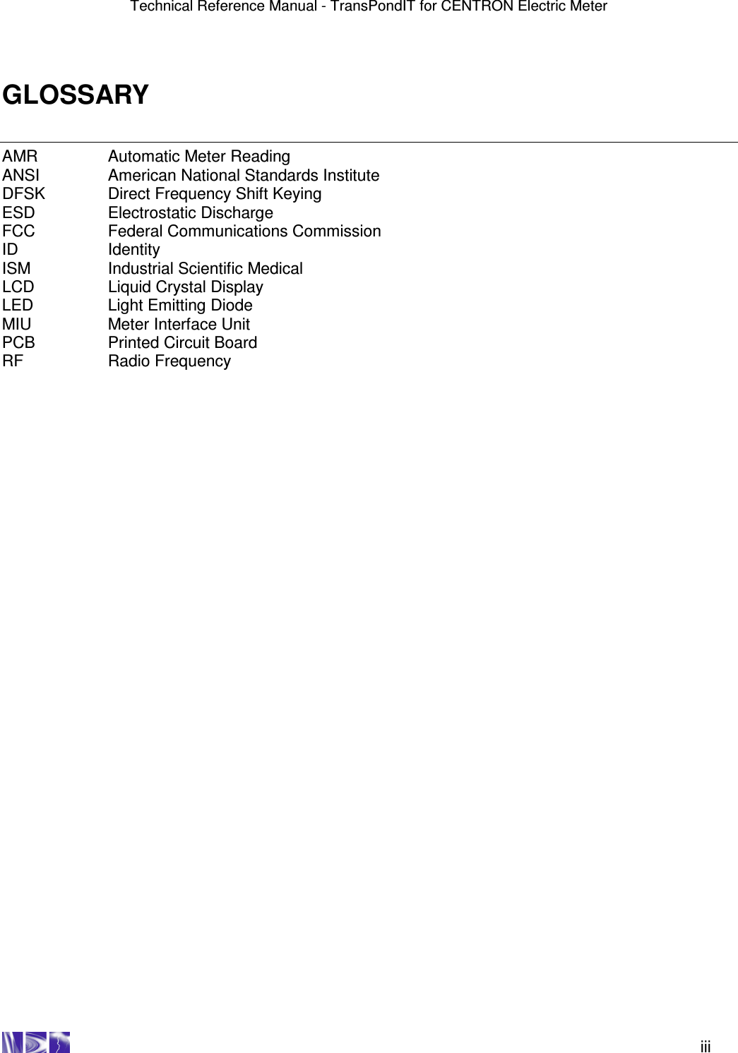
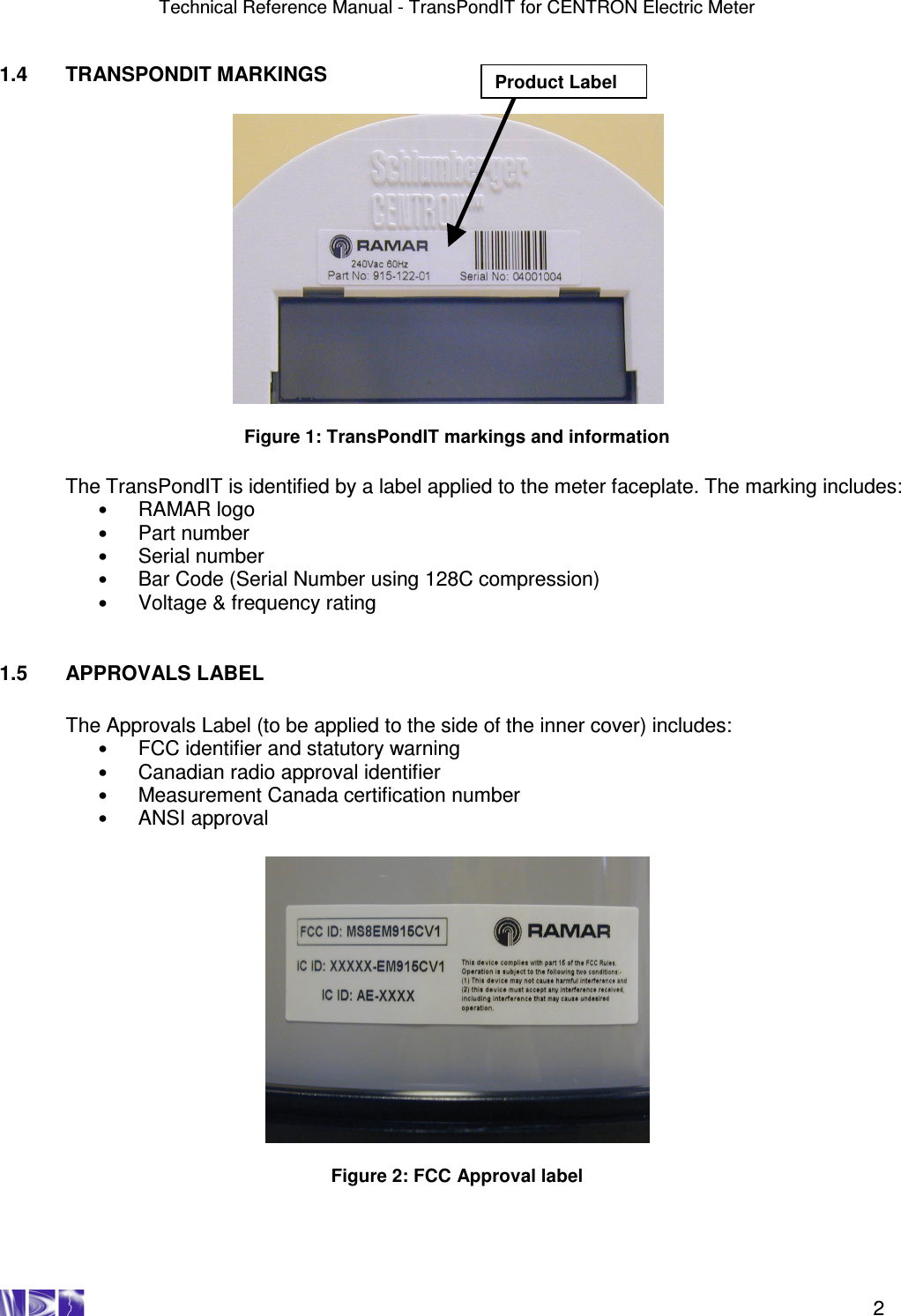
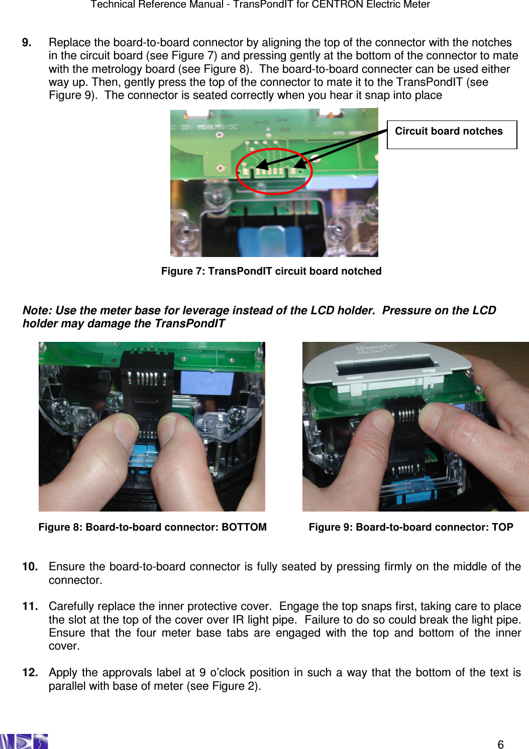
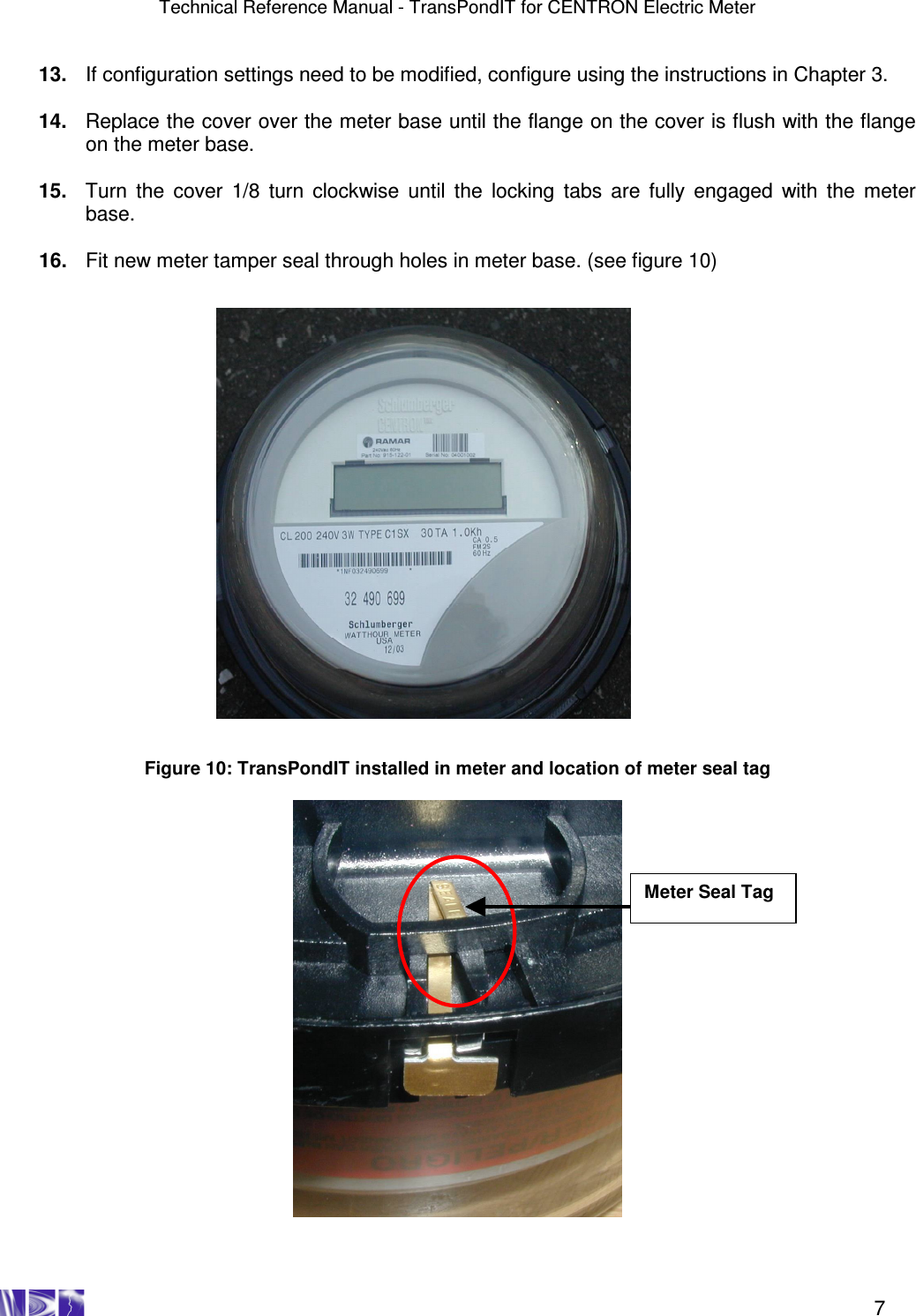
![Technical Reference Manual - TransPondIT for CENTRON Electric Meter 8 Chapter 3: CONFIGURING THE TRANSPONDIT 3.1 DEFAULT CONFIGURATION TransPondITs are delivered with the following default configuration: Parameter Default Setting Meter Reading (kWh) 0 Utility Code 55 TransPondIT ID Factory Serial Number (on barcode) Transmit Interval 5 seconds Status/Error/Tamper Code OK (0) Display format 5*1 Detent option Decrement meter reading on reverse energy flow LCD segment test KWh for 7 seconds, segment test for 1 second Table 1: Default TransPondIT configuration If these settings are acceptable then the TransPondIT is ready to use. If the settings are not acceptable, then the ConFigIT is used to re-program the TransPondIT. 3.2 CONFIGURABLE PARAMETERS The following parameters can be configured: • TransPondIT ID – (Example: to match the meter ID or to match Meter Point ID (0-16777215)). • Meter reading (0 to 99999). • Utility code – (Example: to provide differentiation from TransPondITs on water/gas meters or from those in neighboring utilities (0-255)). • Format of the kWh reading on LCD (5*1 [kWh] or 4*10 [10’s of kWh]). • Reverse count handling function (detent register function). • LCD segment test function. • Status/Error/Tamper code.](https://usermanual.wiki/Blue-Tower-Communications/EM915CV1.Part-1/User-Guide-495803-Page-14.png)