Blue Tower Communications EM915CV1 Electric Meter Reading Transmitter User Manual Part 1
Blue Tower Communications Ltd Electric Meter Reading Transmitter Part 1
Contents
- 1. Part 1
- 2. Part 2
Part 1

PO Box 110127
Research Triangle Park North Carolina 27709-0127
888.98.RAMAR Fax 919.991.9946
www.ramartech.com
Technical Reference Manual
TransPondIT
®
for Itron
®
CENTRON
®
Solid State
Electric Meter
Version 0I (28/09/2004)

Technical Reference Manual - TransPondIT for CENTRON Electric Meter
i
OVERVIEW
About RAMAR
®
RAMAR is a global provider of automatic meter reading (AMR) systems for the utility industry. Through
worldwide license and distribution agreements, RAMAR’s powerful product solutions enable water,
gas, and electric utilities to improve customer service, cost-efficiency, and meter reader safety through
the use of state-of-the-art automation systems. The company’s comprehensive product portfolio
includes basic data capture devices for mobile meter reading, sub-metering, and customized two-way
fixed network system solutions.
RAMAR is a designer and supplier of radio frequency based (RF) AMR systems. RAMAR’s focus is on
developing cutting-edge products for the AMR market. RAMAR specializes in hand-held and mobile
automatic meter reading, with a wide range of uses. Standard interfaces and protocols enable
products to integrate with popular meters, hand-held computers, billing systems and route
management software.
About TransPondIT
®
The TransPondIT is RAMAR’s meter interface unit (MIU), which allows utilities to receive data from a
meter remotely. The TransPondIT collects data from the meter and transmits it by radio to a receiver
and data collection device that is either mobile or fixed.
About CENTRON
®
Meter
The CENTRON Meter is a solid-state electric meter produced by Itron (formerly Schlumberger
Electricity, Inc.).
Features of TransPondIT for CENTRON Meter
• Highly integrated product means competitive cost with strong features.
• No interrogation signal required to ‘wake-up’ TransPondITs.
• No FCC license required.
• Easy, “under-the-glass” installation.
• No battery required - power taken from mains via the meter’s metrology board.
• Meter readings and configuration designed to be unaffected by power surges, brownouts or
other interruptions.
• Programmable display options.
• LCD segment check.
• Detent and non-detent programming options.
• No loss of partial KWh consumption or configuration data during power outages.
• Tilt Switch (option).
• Programmable ID number
• Roll over after 99,999 kWh

Technical Reference Manual - TransPondIT for CENTRON Electric Meter
ii
PREFACE
What is the purpose of this manual?
This manual is intended to provide technical reference on the TransPondIT for CENTRON Meter for
meter shop personnel and those planning the meter reading process. It includes information required
by the meter shop to install and configure a solid state Electric TransPondIT in a CENTRON meter.
Before attempting any installation, testing, or operation of the unit, read this entire manual.
A RAMAR Quick Reference Guide is also available which covers the 900 series TransPondIT,
ConFigIT, FastTrackIT
and HandTrackIT
. Contact your RAMAR distributor for a copy of this guide.
Who do I contact if I have a question?
Questions not covered by this manual should be directed to your RAMAR distributor. If a distributor is
not available, contact RAMAR directly by calling 1-888-98-RAMAR (72627).

Technical Reference Manual - TransPondIT for CENTRON Electric Meter
iii
GLOSSARY
AMR Automatic Meter Reading
ANSI American National Standards Institute
DFSK Direct Frequency Shift Keying
ESD Electrostatic Discharge
FCC Federal Communications Commission
ID Identity
ISM Industrial Scientific Medical
LCD Liquid Crystal Display
LED Light Emitting Diode
MIU Meter Interface Unit
PCB Printed Circuit Board
RF Radio Frequency

Technical Reference Manual - TransPondIT for CENTRON Electric Meter
iv
TABLE OF CONTENTS
OVERVIEW ........................................................................................................................................................ i
PREFACE.......................................................................................................................................................... ii
GLOSSARY...................................................................................................................................................... iii
TABLE OF CONTENTS................................................................................................................................... iv
CHAPTER 1: GETTING STARTED .................................................................................................................. 1
1.1
General................................................................................................................................................ 1
1.2
Meter Compatibility.............................................................................................................................. 1
1.3
Kit Contents......................................................................................................................................... 1
1.4
TransPondIT Markings ........................................................................................................................ 2
1.5
Approvals Label................................................................................................................................... 2
CHAPTER 2: INSTALLATION.......................................................................................................................... 3
2.1
Handling Precautions .......................................................................................................................... 3
2.2
Inspection ........................................................................................................................................... 3
2.3
Meter Preparation................................................................................................................................ 3
2.4
Safety .................................................................................................................................................. 3
2.5
TransPondIT Installation ..................................................................................................................... 4
Chapter 3: CONFIGURING THE TRANSPONDIT........................................................................................... 8
3.1
Default Configuration .......................................................................................................................... 8
3.2
Configurable parameters..................................................................................................................... 8
3.3
Preparation of ConFigIT ...................................................................................................................... 9
3.4
Use of ConFigIT PC Software........................................................................................................... 11
CHAPTER 4: TECHNICAL INFORMATION................................................................................................... 15
4.1 Specification........................................................................................................................................... 15
4.2 Regulatory & Standards......................................................................................................................... 15
4.3 Measurement and Display ..................................................................................................................... 15
4.3.1 General............................................................................................................................................ 15
4.3.2 Energy Consumption Register ........................................................................................................ 15
4.3.3 Reverse Consumption..................................................................................................................... 16
4.3.4 LCD Segment Test.......................................................................................................................... 16
4.3.5 LCD Contrast................................................................................................................................... 16
4.3.6 Watt Disc Emulator.......................................................................................................................... 16
4.4
Radio Communications ..................................................................................................................... 17
4.4.1 Operational Range .......................................................................................................................... 17
4.4.2 Transmit Carrier Frequency ............................................................................................................ 17
4.4.3 Antenna ........................................................................................................................................... 17
4.4.4 Transmission Interval ...................................................................................................................... 17
4.4.5 Meter Reading Transmission Format.............................................................................................. 17
CHAPTER 5: STATUS CONDITIONS & TROUBLESHOOTING................................................................... 18
5.1
Status Conditions .............................................................................................................................. 18

Technical Reference Manual - TransPondIT for CENTRON Electric Meter
v
5.2
Reading and Clearing Status Conditions with ConFigIT................................................................... 19
5.2.1 Clear a Status Code ........................................................................................................................ 20
5.2.2 Troubleshooting – General.............................................................................................................. 23
5.2.3 Troubleshooting - Configuration...................................................................................................... 23
APPENDIX A: METER COMPATIBILITY CHART & PART NUMBERS ....................................................... 25
APPENDIX B: TRANSPONDIT STATUS CODES ......................................................................................... 26
APPENDIX D: COMMERCIAL HEALTH AND SAFETY INFORMATION ..................................................... 32

Technical Reference Manual - TransPondIT for CENTRON Electric Meter
1
CHAPTER 1: GETTING STARTED
This chapter provides an overview of function, meter compatibility and product marking.
1.1 GENERAL
The RAMAR TransPondIT for the CENTRON meter implements the TransPondIT functionality into the
Itron (formerly Schlumberger Electricity, Inc.) CENTRON solid state electricity meter. It is a
personality module with the functions of meter, register, display and RF Transmitter. The
TransPondIT is supplied fitted with the LCD and meter face plate.
Mounting of the TransPondIT in the meter takes only a few seconds and requires no tools and minimal
operator training. The TransPondIT is fitted to new or existing meters in utility meter shop or by a 3
rd
party meter service company. Alternatively, utilities can buy meters with the personality module
already installed.
If settings on the TransPondIT need to be modified, an electric ConFigIT is used to reconfigure the
TransPondIT prior to sealing the meter.
1.2 METER COMPATIBILITY
The CENTRON meter features several meter bases in a number of form factors. Appendix A includes
a table of TransPondIT part numbers used with the various meter form factors. If purchasing meters
for fitting TransPondITs, order meters without the standard personality module (C1SX). Qualification
of the meter with TransPondIT fitted is still pending for some form factors.
TransPondITs are available for order with a tilt switch option – refer to your RAMAR representative for
availability. The tilt switch reports removal of meter or inverted operation of the meter
.
1.3 KIT CONTENTS
The items in the TransPondIT package are:
• TransPondITs
• Sheet of Approvals labels
• Sheet of ‘X10’ labels
Technical Reference Manual - TransPondIT for CENTRON Electric Meter
2
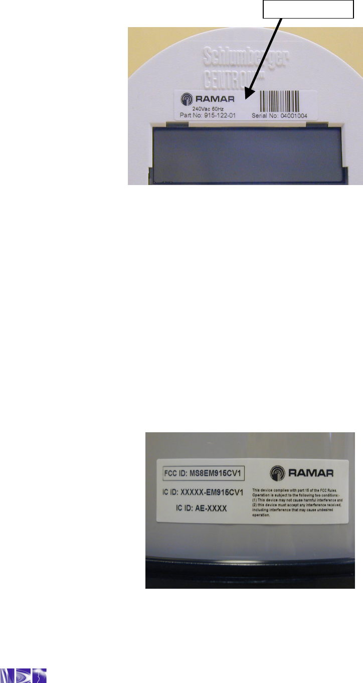
1.4 TRANSPONDIT MARKINGS
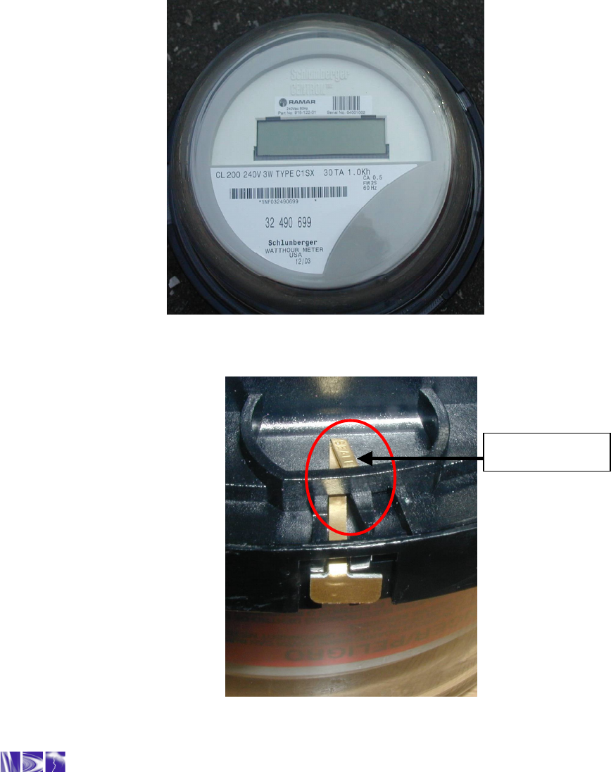
Figure 1: TransPondIT markings and information
The TransPondIT is identified by a label applied to the meter faceplate. The marking includes:
•
RAMAR logo
•
Part number
•
Serial number
•
Bar Code (Serial Number using 128C compression)
•
Voltage & frequency rating
1.5 APPROVALS LABEL
The Approvals Label (to be applied to the side of the inner cover) includes:
•
FCC identifier and statutory warning
•
Canadian radio approval identifier
•
Measurement Canada certification number
•
ANSI approval
Figure 2: FCC Approval label
Product Label

Technical Reference Manual - TransPondIT for CENTRON Electric Meter
3
CHAPTER 2: INSTALLATION
This chapter provides instructions for the proper installation of the TransPondIT.
2.1 HANDLING PRECAUTIONS
When handling the TransPondIT, grip the circuit board by its edges. DO NOT touch the LCD display
or the electronics components.
2.2 INSPECTION
Perform the following inspections when you receive the TransPondITs:
•
Compare and verify the TransPondIT serial number and part number (see Figure 1) to the
packing slip and invoice.
•
Inspect for damage to the LCD plastic housing, LCD and PCB.
•
Peel off protective strip from LCD.
2.3 METER PREPARATION
Perform any cleaning and preparation to the meter prior to fitting the TransPondIT.
2.4 SAFETY
The TransPondIT is powered via connections to the meter’s metrology board. The connection is
achieved using a board-to-board connector supplied with the meter.
Do not power the meter from mains without the inner cover in place.
Remove power from the meter before removing the inner cover.
Technical Reference Manual - TransPondIT for CENTRON Electric Meter
4
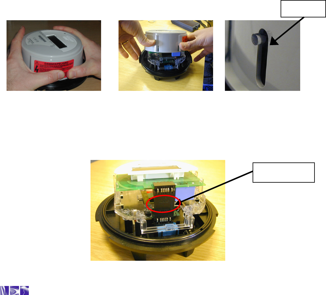
2.5 TRANSPONDIT INSTALLATION
To change or fit the TransPondIT:
1. Remove power from the meter.
2. Remove the outer (polycarbonate or glass) cover (twist off).
3. Remove plastic inner cover by holding the meter with both hands and applying equal
pressure on either side of the three and nine-o’clock positions (see Figure 3a). The inner
cover is held in place by four plastic tabs on the meter base.
4. With the meter facing the user and the plastic tabs disengaged, tilt the cover away (see
Figure 3b).
5. Lift off the meter base taking care not to catch the light pipe. The light pipe could be
damaged if you lift the cover straight up (see Figure 3c).
Figure 3a Figure 3b Figure 3c
Figure 3a, 3b, 3c: Removing the inner protective cover
6. Remove the black board-to-board connector between the upper circuit board (if present) and
the metrology board. Grasp the board in the middle, lengthwise, and pull out by moving from
side-to-side (see Figure 4). To maintain the integrity of the connector, only remove it when
fitting TransPondIT
.
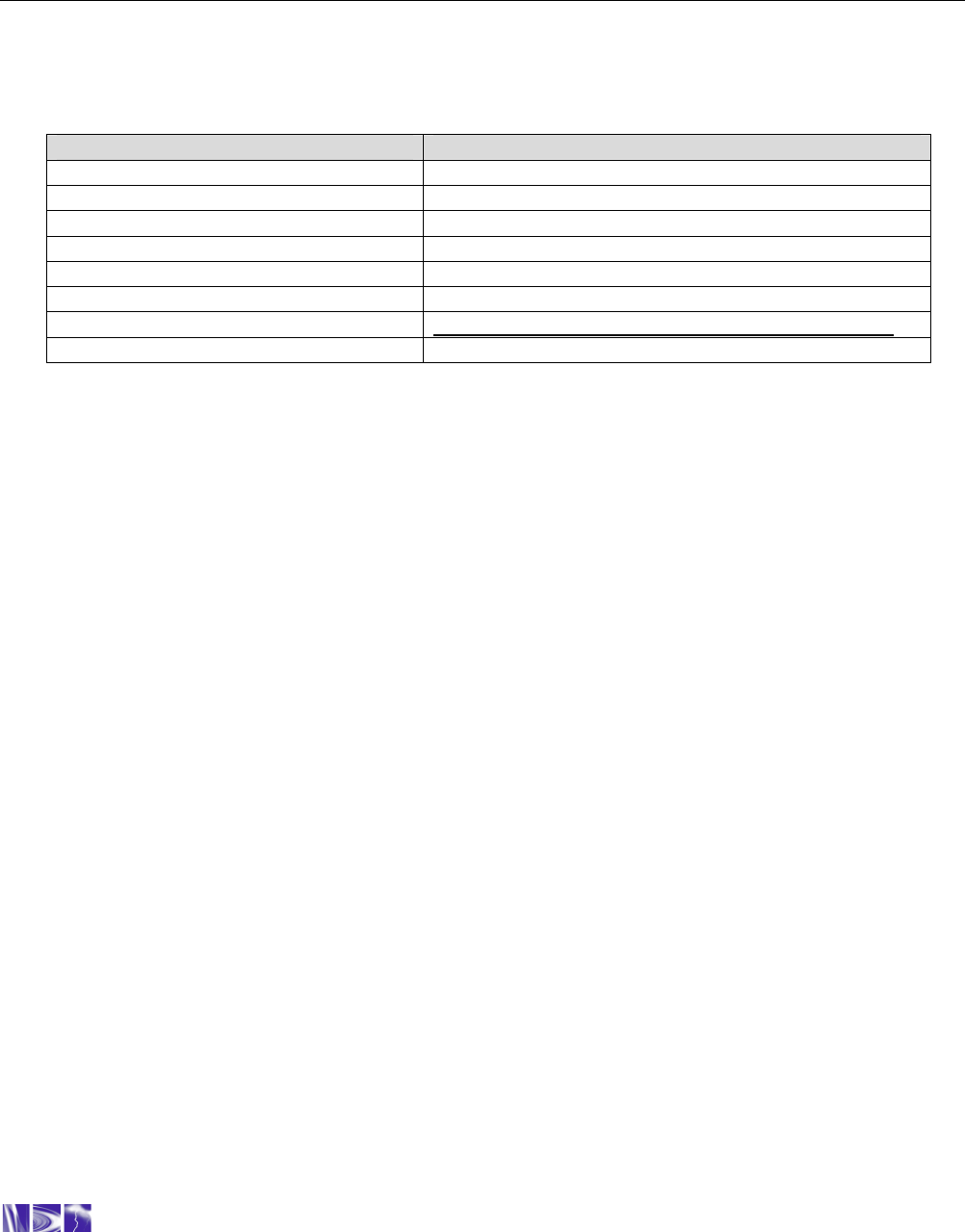
Figure 4: Removing the board to board connector
Board to board
connector
Light Pipe
Technical Reference Manual - TransPondIT for CENTRON Electric Meter
5
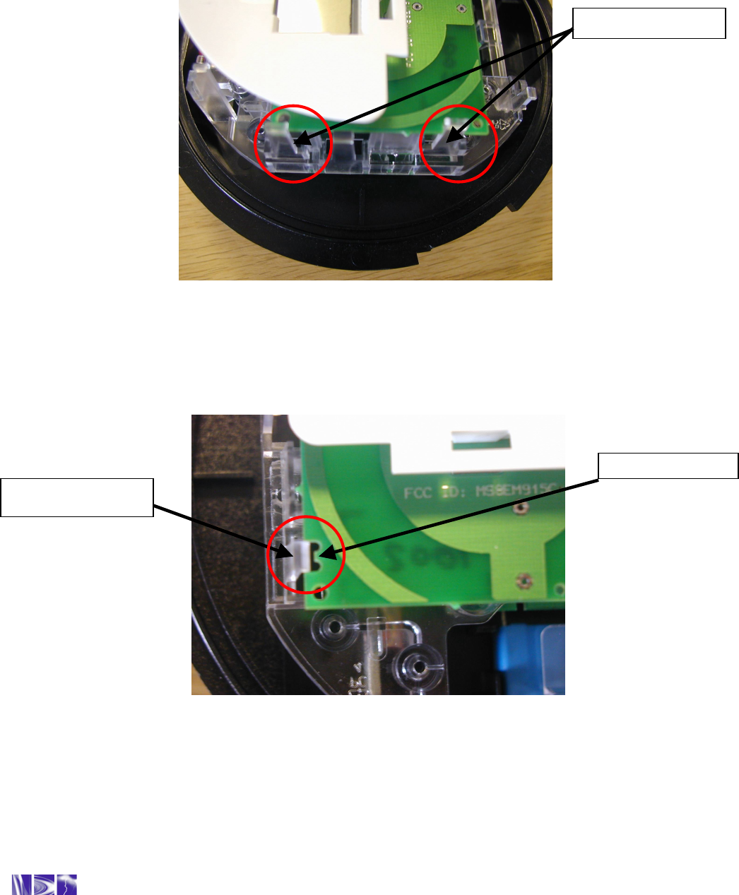
7. Remove the upper circuit board (if fitted), one side at a time, by pulling gently outwards on
the meter frame snaps (see Figure 5) while lifting the module up.
Figure 5: Meter frame snaps
8. Snap the new module into the meter frame by aligning the notches at the bottom of the
circuit board with the lower two snaps (see Figure 6).
Figure 6: Alignment of PCB notch with meter snap
NOTE: The module must be aligned properly in the snaps to avoid damage to the
connector or circuit board.
Meter frame snaps
PCB lower notch
Lower meter snap
Technical Reference Manual - TransPondIT for CENTRON Electric Meter
6
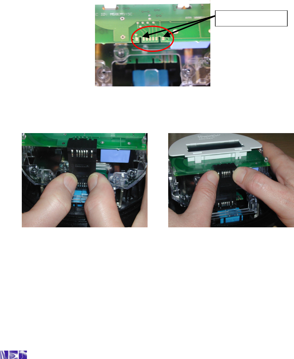
9. Replace the board-to-board connector by aligning the top of the connector with the notches
in the circuit board (see Figure 7) and pressing gently at the bottom of the connector to mate
with the metrology board (see Figure 8). The board-to-board connecter can be used either
way up. Then, gently press the top of the connector to mate it to the TransPondIT (see
Figure 9). The connector is seated correctly when you hear it snap into place
Figure 7: TransPondIT circuit board notched
Note: Use the meter base for leverage instead of the LCD holder. Pressure on the LCD
holder may damage the TransPondIT
Figure 8: Board-to-board connector: BOTTOM Figure 9: Board-to-board connector: TOP
10. Ensure the board-to-board connector is fully seated by pressing firmly on the middle of the
connector.
11. Carefully replace the inner protective cover. Engage the top snaps first, taking care to place
the slot at the top of the cover over IR light pipe. Failure to do so could break the light pipe.
Ensure that the four meter base tabs are engaged with the top and bottom of the inner
cover.
12. Apply the approvals label at 9 o’clock position in such a way that the bottom of the text is
parallel with base of meter (see Figure 2).
Circuit board notches
Technical Reference Manual - TransPondIT for CENTRON Electric Meter
7
13. If configuration settings need to be modified, configure using the instructions in Chapter 3.
14. Replace the cover over the meter base until the flange on the cover is flush with the flange
on the meter base.
15. Turn the cover 1/8 turn clockwise until the locking tabs are fully engaged with the meter
base.
16. Fit new meter tamper seal through holes in meter base. (see figure 10)
Figure 10: TransPondIT installed in meter and location of meter seal tag
Meter Seal Tag
Technical Reference Manual - TransPondIT for CENTRON Electric Meter
8
Chapter 3: CONFIGURING THE TRANSPONDIT
3.1 DEFAULT CONFIGURATION
TransPondITs are delivered with the following default configuration:
Parameter
Default Setting
Meter Reading (kWh) 0
Utility Code 55
TransPondIT ID Factory Serial Number (on barcode)
Transmit Interval 5 seconds
Status/Error/Tamper Code OK (0)
Display format 5*1
Detent option Decrement meter reading on reverse energy flow
LCD segment test KWh for 7 seconds, segment test for 1 second
Table 1: Default TransPondIT configuration
If these settings are acceptable then the TransPondIT is ready to use. If the settings are not
acceptable, then the ConFigIT is used to re-program the TransPondIT.
3.2 CONFIGURABLE PARAMETERS
The following parameters can be configured:
• TransPondIT ID – (Example: to match the meter ID or to match Meter Point ID (0-16777215)).
• Meter reading (0 to 99999).
• Utility code – (Example: to provide differentiation from TransPondITs on water/gas meters or
from those in neighboring utilities (0-255)).
• Format of the kWh reading on LCD (5*1 [kWh] or 4*10 [10’s of kWh]).
• Reverse count handling function (detent register function).
• LCD segment test function.
• Status/Error/Tamper code.

Technical Reference Manual - TransPondIT for CENTRON Electric Meter
9
3.3 PREPARATION OF CONFIGIT
The TransPondIT is configured by RAMAR’s ConFigIT electric serial adaptor. The ConFigIT
interfaces to the TransPondIT using a physical cable connection. The ConFigIT powers the
TransPondIT during configuration - TransPondITs can be configured either on the bench (out of
meter) or in the meter.
The TransPondIT should not be mains powered during the configuration process.
The ConFigIT kit includes:
• ConFigIT box
• ‘Computer’ serial cable (Connections are wired straight through, terminated at both ends with
9-pin female ‘D’ connectors – NOTE not same as for letterbox ConFigIT for Water
TransPondIT).
• ‘TransPondIT’ serial cable (Note: order spares from your CENTRON Meter supplier as ‘Zeroer
Cable’ – Itron part no K442436-001)
• CENTRON meter plug (Note: order spares from your CENTRON Meter supplier as ‘Zeroer
Assy Welded’ – Itron part no K442395-001)
The ConFigIT is powered by 2 AA alkaline batteries (not included in kit). The battery compartment is
on the rear of ConFigIT.
Another option is to power the ConFigIT with an external DC power supply (6-12VDC @ 200mA – not
included in kit).
The ConFigIT application must be configured so that it uses the COM port that the TransPondIT is
connected to. If the wrong COM port is used, then the error message as illustrated in figure 24 is
displayed. To change the COM port interface, select File – Interface from the menu and select the
correct COM port.
When battery operated, the ConFigIT On/Standby LED illuminates once the ConFigIT program is
running and the correct COM port is selected. If the ConFigIT is not used for more than 20 seconds,
the ‘standby’ mode activates indicated by a flashing On/Standby LED. The ConFigIT returns to its
normal mode if there is communication activity within 60 seconds. If there is no activity before 60
seconds, the ConFigIT powers down and the LED turns off.
If the ConFigIT is powered by an external DC supply, it does not enter ‘standby’ mode or power down.