Blue Tower Communications EM915CV1 Electric Meter Reading Transmitter User Manual Part 2
Blue Tower Communications Ltd Electric Meter Reading Transmitter Part 2
Contents
- 1. Part 1
- 2. Part 2
Part 2
Technical Reference Manual - TransPondIT for CENTRON Electric Meter
10
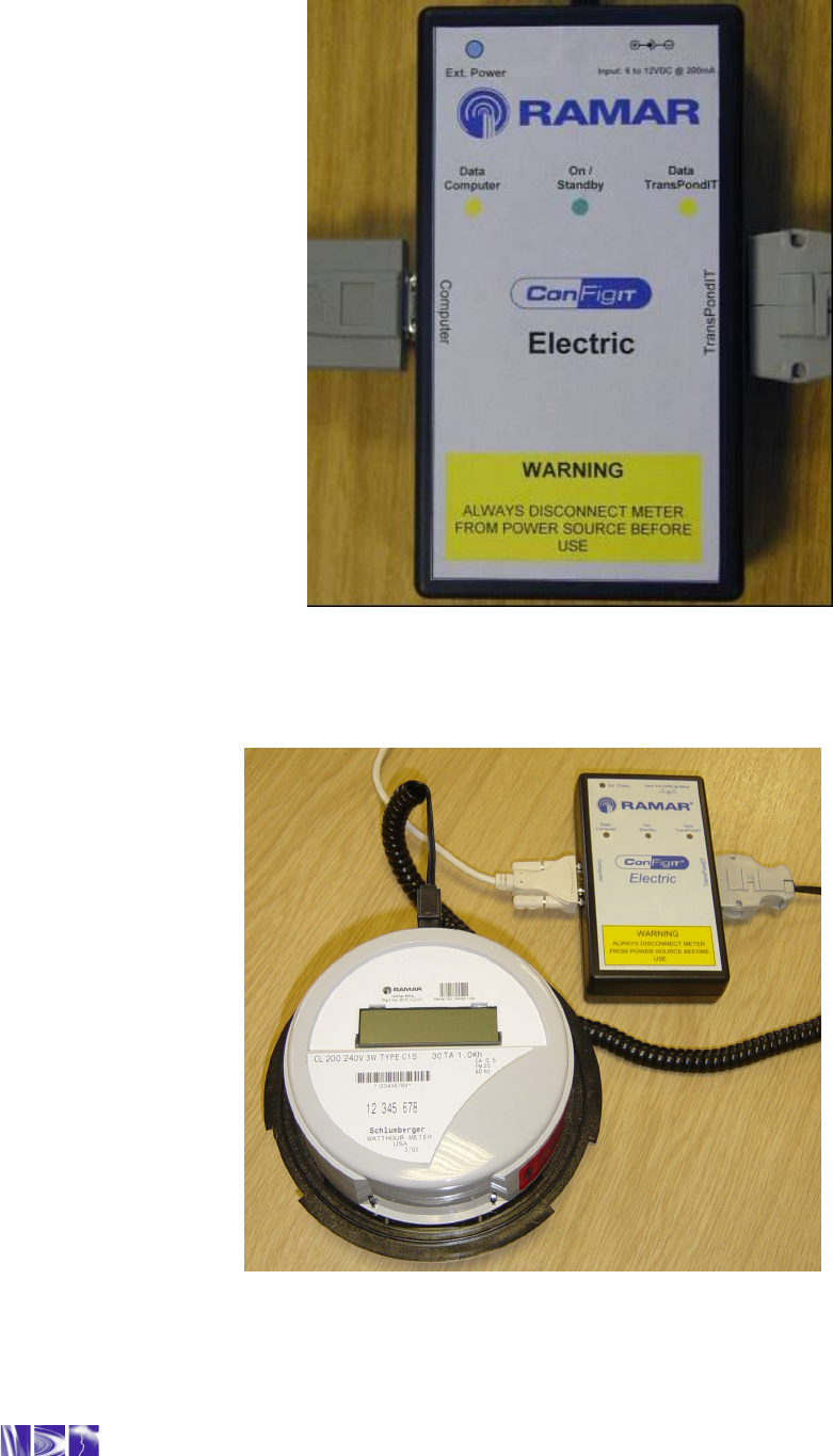
Figure 11: ConFigIT Electric Serial adaptor
Figure 12: Electric ConFigIT connected to the TransPondIT
Technical Reference Manual - TransPondIT for CENTRON Electric Meter
11
3.4 USE OF CONFIGIT PC SOFTWARE
1. If you have ConFigIT PC software loaded on the PC, check that it is Version 6.4 or higher. If
not, download self extracting zip file from www.ramartech.com/products/configit/ (Download
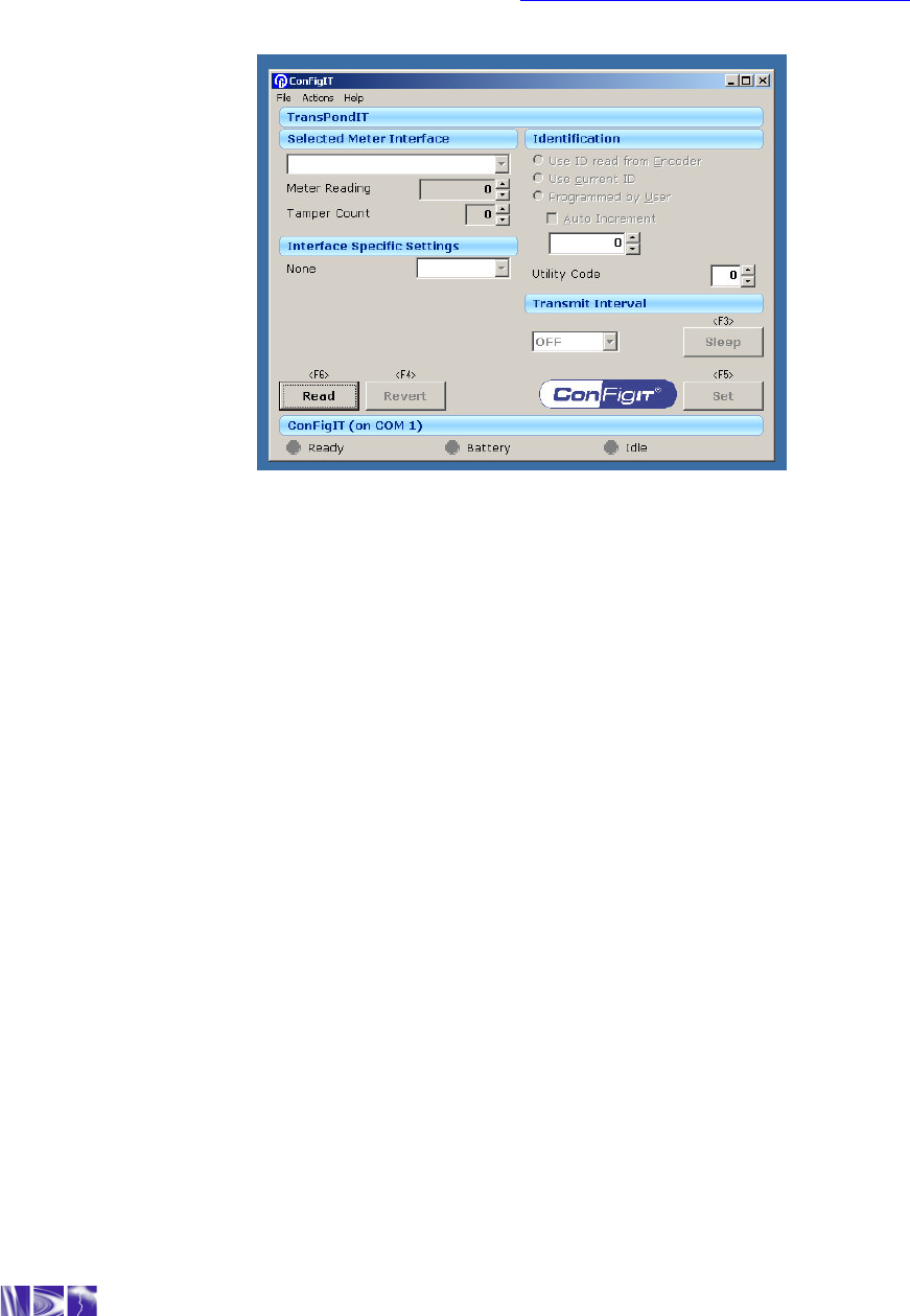
instructions are provided on same web page). Start the program (see Figure 13).
Figure 13: ConFigIT application screen
2. Activate program by selecting ‘Help’ followed by ‘Product Activation’. Software will work for
28 days before it will need re-activation.
3. Select ‘Request’ button. This generates a Request Code specific to the PC. The Request
Code is sent to RAMAR Technical Support by email (recommended) or by telephone. A
dialogue box for emailing Product Activation Request Code details is provided to help with
this process – enter User Details into the box, click the ‘Send Email’ option and select ‘OK’
button. An email is generated if there is an email program installed on the PC.
4. RAMAR Technical Support responds with an Activation Code. Cut and paste this code into
the Product Activation dialogue box. (If manually entering be careful to enter Activation code
exactly as it appears paying attention to spaces and upper/lower case) and select ‘OK’
button.
5. The serial COM port connection is configured by selecting File – Interface and then selecting
the appropriate COM port from the drop down menu.
6. Connect the ‘Computer’ cable to RS232 port of computer (or to a USB port via a USB to
RS232 interface device)
7. The TransPondIT is configured either when in the meter or separately on the bench before
fitting. If configuring the TransPondIT in the meter, ensure the meter is not connected to
mains.
Technical Reference Manual - TransPondIT for CENTRON Electric Meter
12
WARNING: Disconnect the meter from the mains BEFORE connecting the
TransPondIT to the ConFigIT.
8. If configuring the TransPondIT in the meter, first remove the meter tamper seal. Then
remove the meter’s outer cover (twist counter- clockwise) and then connect the ConFigIT
‘TransPondIT’ cable to the TransPondIT with the electrical connections facing “up”. When
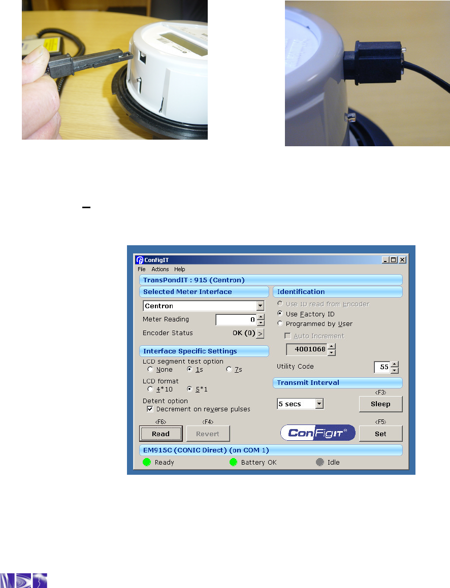
correctly installed the connector will “click” into place (see Figures 14a & 14b).
Figure 14a Figure 14b
Figures 14a & b: Connection of ConFigIT Electric to TransPondIT
9. Select Read (or press F6). The ‘Data Computer’ LED on the ConFigIT flashes and the
ConFigIT screen changes to one as shown in Figure 15. If an error message is displayed,
refer to troubleshooting instructions in section 5.2.2 and Appendix B
.
Figure 15: Configuration Screen

Technical Reference Manual - TransPondIT for CENTRON Electric Meter
13
10. The following actions are performed to change the default TransPondIT settings, shown in
Table 1. Invalid data entries are highlighted in red on the screen.
• To change the meter reading: Highlight the current meter reading and enter the new
value. Acceptable values are 0 to 99999.
• To change the utility code: Highlight the current value and enter the new value.
Acceptable values are 000 to 255.
• To change the TransPondIT serial number: Select the ‘Programmed by User’ radio
button option and enter the new value. The acceptable range is 0 to 16777215.
• To set the TransPondIT serial number to the factory default: Select ‘Use Factory ID’
• To change the transmit interval: Click on the ‘down arrow’ symbol next to the current
transmit interval and select one from the drop down menu. Options are: OFF, 5 seconds,
10 seconds and 20 seconds. Select 5 seconds.
• To change the display format: Select using the radio button. Options available are: 5*1
(displays the meter reading in KWh) or 4*10 (displays the readings in 10’s of kWh). If
using the 4*10 option; apply “x10” label (supplied with TransPondIT) on meter fascia
panel to right of display.
Example: Energy consumption = 12345kWh
•
LCD format is 5*1. LCD displays 12345 (kWh)
•
LCD format is 4*10. LCD displays 1234 (10’s of kWh)
•
Transmitted radio reading is 12345 (kWh) – Always in 5*1 format.
• To change the detent setting use check box provided:
Unchecked Only forward energy flow will be accumulated (ignore reverse energy).
Checked Decrement the meter reading on detection of reverse energy.
• To change the LCD segment test option: Select the appropriate radio button. Options
are:
None - No segment test (Only display kWh)
1s - Display kWh for 7 seconds then segment test for 1 second
7s - Display kWh for 7 seconds then segment test for 7 seconds
11. Once the changes are selected, select Set (or press F5). This writes the new configuration
to the TransPondIT.
The TransPondIT automatically responds to a Set command with a configuration report. The
ConFigIT software verifies the report against the requested settings and displays an error
dialogue box if there is a mismatch.
Selecting Revert displays the TransPondIT’s original factory default settings. The settings are
saved to the TransPondIT by pressing Set.

Technical Reference Manual - TransPondIT for CENTRON Electric Meter
14
Changes to the TransPondITs configuration are immediate but changes to LCD format are not
visible until the LCD format is displayed. Cycling the TransPondIT’s power (unplugging
ConFigIT from TransPondIT refreshes the LCD format.
The ConFigIT PC software always reports the meter reading in kWh, irrespective of the LCD
display format (5*1 OR 4*10). The transmitted radio reading is always in kWh.
Example: Energy consumption = 12345kWh
- LCD format is 5*1. LCD displays 12345 (kWh)
- LCD format is 4*10. LCD displays 1234 (10’s of kWh)
- Transmitted radio reading is 12345 (kWh)

Technical Reference Manual - TransPondIT for CENTRON Electric Meter
15
CHAPTER 4: TECHNICAL INFORMATION
4.1 SPECIFICATION
• Wireless Specification: Operates in the 902 MHz to 928 MHz license exempt ISM band.
• Operating Temperature: -40
0
F to +185
0
F (-40
0
C to +85
0
C)
• Operating Voltage: 240VAC ± 20% (120VAC optional)
• Power Consumption: 0.5W nominal and 7VA (240VAC, 60Hz)
• Data Format: Data is sent in fixed length, error checked, encoded data packets.
• Configuration options: Utility code, ID number, display format, meter reading, transmission
interval, detent/non detent
• Tamper Detection: Error code in message indicates if reverse counts or meter tilted (with
tilt switch option).
• Weight: 1.7 ounces (including LCD)
• Dimensions (approximate): H 3.5” x W 4.25” x D 1.2” (including LCD)
4.2 REGULATORY & STANDARDS
• FCC Part 15 (Class B device). – Radiated and conducted emissions
• ANSI C12.1 – 2001 (Tests applicable to AMR device)
• ANSI 12.20 (Class 0.5 – 1998): American National Standards for Electricity Meters
• ANSI C37.90.1 (1994): Standard Surge Withstand Capability (SWC) Tests
• IEC 61000-4-2 (1995): Electrostatic discharge immunity test
• IEC 61000-4-4 (1995): Electrical fast transient burst immunity test.
• IEC 60068-2-6 (1995-03): Basic Environmental Testing Procedure: Mechanical Vibration
• IEC 60068-2-27 (1997-06): Basic Environmental Testing Procedure: Mechanical Shock
• IC RSS210: Industry Canada Specification for Approval of Low Power, License Exempt
Radio Communication devices
• IC LMB-EG-07: Industry Canada Specification for Type Approval of Electric Meter
4.3 MEASUREMENT AND DISPLAY
4.3.1 General
The TransPondIT is connected to the metrology board using the board-to-board
connector. Energy pulses (1 pulse per Watt Hour consumed) and energy flow direction
are sent to the TransPondIT from the metrology board.
4.3.2 Energy Consumption Register
• The TransPondIT register for energy consumption holds a count of Wh. Electricity
usage is metered by counting pulses generated by the metrology board. Energy
flow direction is also indicated by the metrology board.
• The register contents are stable during power outage – there is no loss of partial
kWh consumption if there is an outage.
• The LCD displays energy consumption in kWh (or 10’s of kWh according to display
format option selected).
Technical Reference Manual - TransPondIT for CENTRON Electric Meter
16
4.3.3 Reverse Consumption
Reverse energy is handled according to the detent setting option. The register is
configured such that:
1) Reverse energy flow decrements the value of the register, or
2)
Reverse energy flow does not change the value of the register
.
4.3.4 LCD Segment Test
An LCD segment test is provided (all numbers are 8’s). Three options are available:
1) Display kWh only
2) Display kWh for 7 seconds, segment test for 1 second (Default)
3) Display kWh for 7 seconds, segment test for 7 seconds
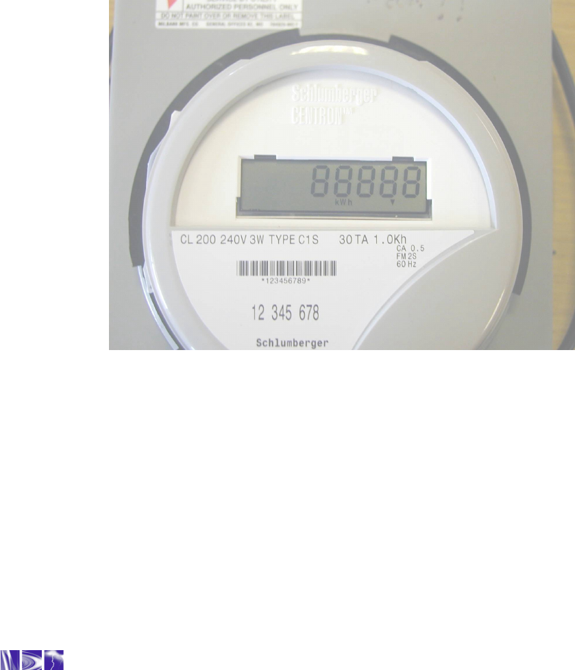
Figure 16: LCD showing segment test (5*1 format)
4.3.5 LCD Contrast
The LCD is automatically adjusted for contrast over the operating temperature range.
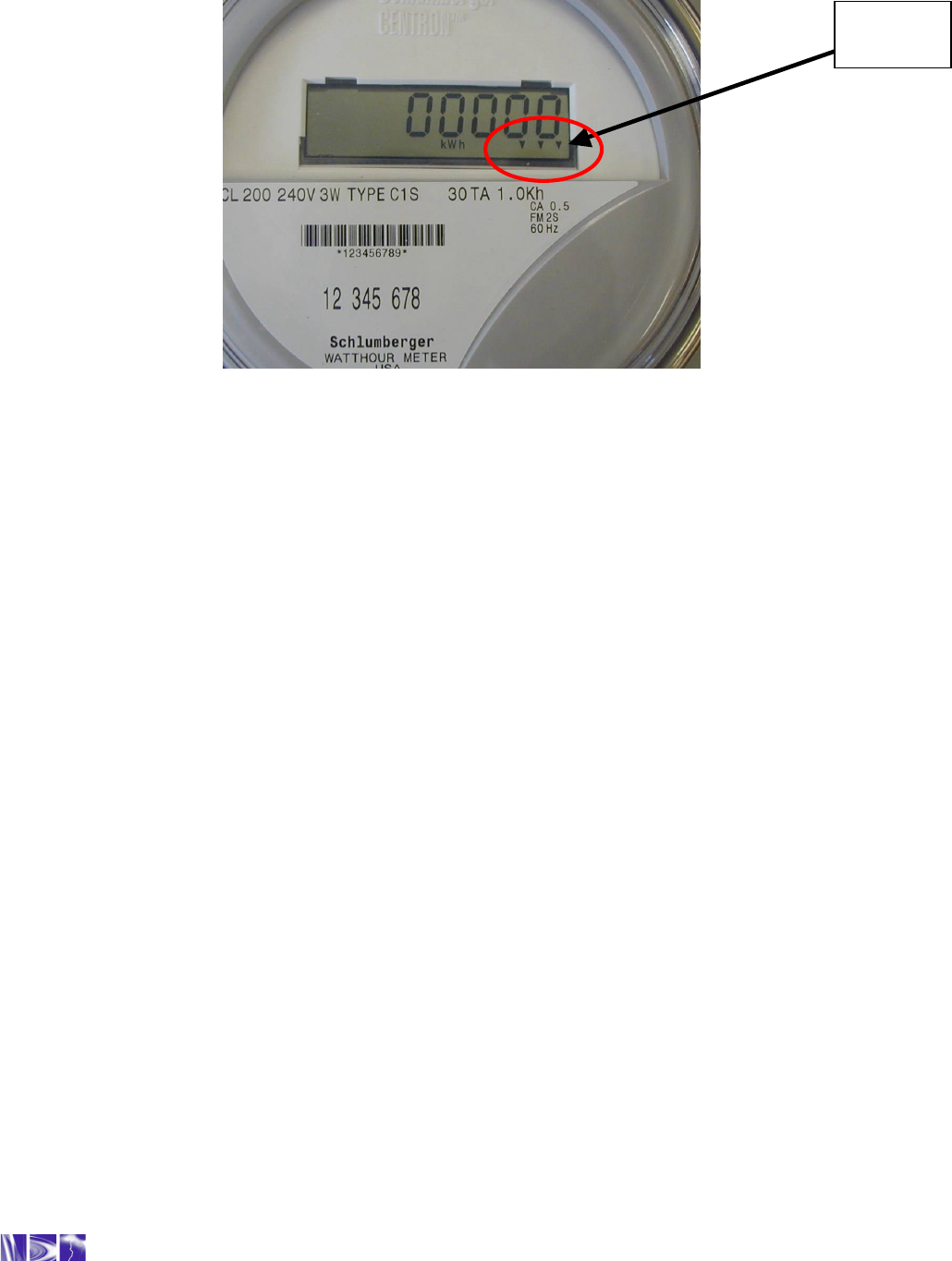
4.3.6 Watt Disc Emulator
The energy flow direction is indicated by sequentially flashing three downward pointing
arrows’ from left to right indicating forward energy usage and from right to left indicating
reverse energy usage. Each arrow is ‘on’ for 1 watt-hour and ‘off’ for 1 watt-hour (see
figure 17).
Technical Reference Manual - TransPondIT for CENTRON Electric Meter
17
Figure 17: LCD showing watt-disc emulator
4.4 RADIO COMMUNICATIONS
4.4.1 Operational Range
The operational range is typically greater than 300 ft (unobstructed line-of-sight as
reported using a FastTrackIT with an antenna at a height of 5 ft). The actual range
varies depending on the characteristics of the location.
4.4.2 Transmit Carrier Frequency
The nominal transmission frequency operates within the ISM band 902 - 928MHz.
4.4.3 Antenna
The antenna is integral to the TransPondIT and printed on the PCB
.
4.4.4 Transmission Interval
The transmit interval is configurable: OFF, 5, 10 & 20 seconds. Default = 5 seconds.
4.4.5 Meter Reading Transmission Format
The meter reading always transmits in kWh, irrespective of the LCD display format
option (5*1 or 4*10).
Watt-
Disc
Emulator

Technical Reference Manual - TransPondIT for CENTRON Electric Meter
18
CHAPTER 5: STATUS CONDITIONS &
TROUBLESHOOTING
This chapter describes the TransPondIT status conditions and the mechanisms behind activation. It
also covers troubleshooting steps, if a problem arises with the installation or configuration process.
5.1 STATUS CONDITIONS
Several status conditions are flagged and reported by the TransPondIT in the radio message.
Table 2 lists the possible conditions and associated status code and type.
STATUS CODE STATUS TYPE
Reverse Energy Flow 1 Non-fatal
Metrology Board Error 2 Fatal
CAL Filtering 4 Non-fatal
Non-volatile memory fault 8 Fatal
Tilt Switch Activated (if fitted) 16 Non-fatal
Table 2: Status Conditions
A fatal error is one in which the meter count is halted. As the setting of the error flag is stored
in the NVRAM, removing and restoring mains supply will have no effect. The last ‘good’
reading will continue to be written to the display (and transmitted in the RF message) and the
error flag will be present in the RF message. Note: the “watt-disc emulator” will still be
functioning. To resume normal operation, the error flag MUST be reset via the ConFigIT (see
below).
A Non-fatal error is one that provides information only – it does not affect the count.
A complete list of status codes in the form they are received by HandTrackIT or FastTrackIT is
provided in Appendix B.
Instructions for identifying and correcting possible causes of the error are described in
Appendix C.
Technical Reference Manual - TransPondIT for CENTRON Electric Meter
19
5.2 READING AND CLEARING STATUS CONDITIONS WITH CONFIGIT
All status codes reported by the TransPondIT are read and cleared using the ConFigIT.
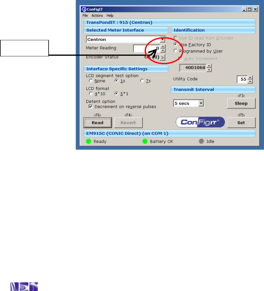
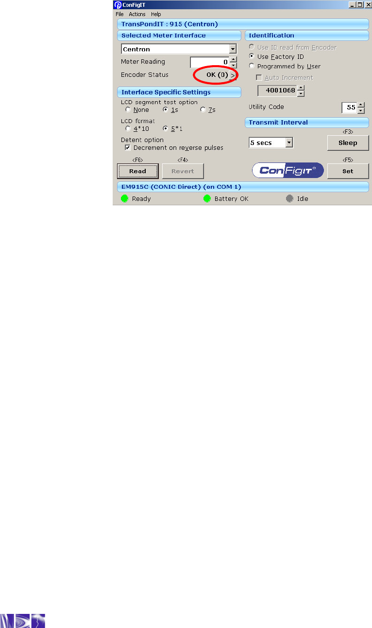
• When displayed by the ConFigIT PC Software, a status code of 0 indicates normal
operation (see Figure 18). The specific code number is enclosed in brackets ().
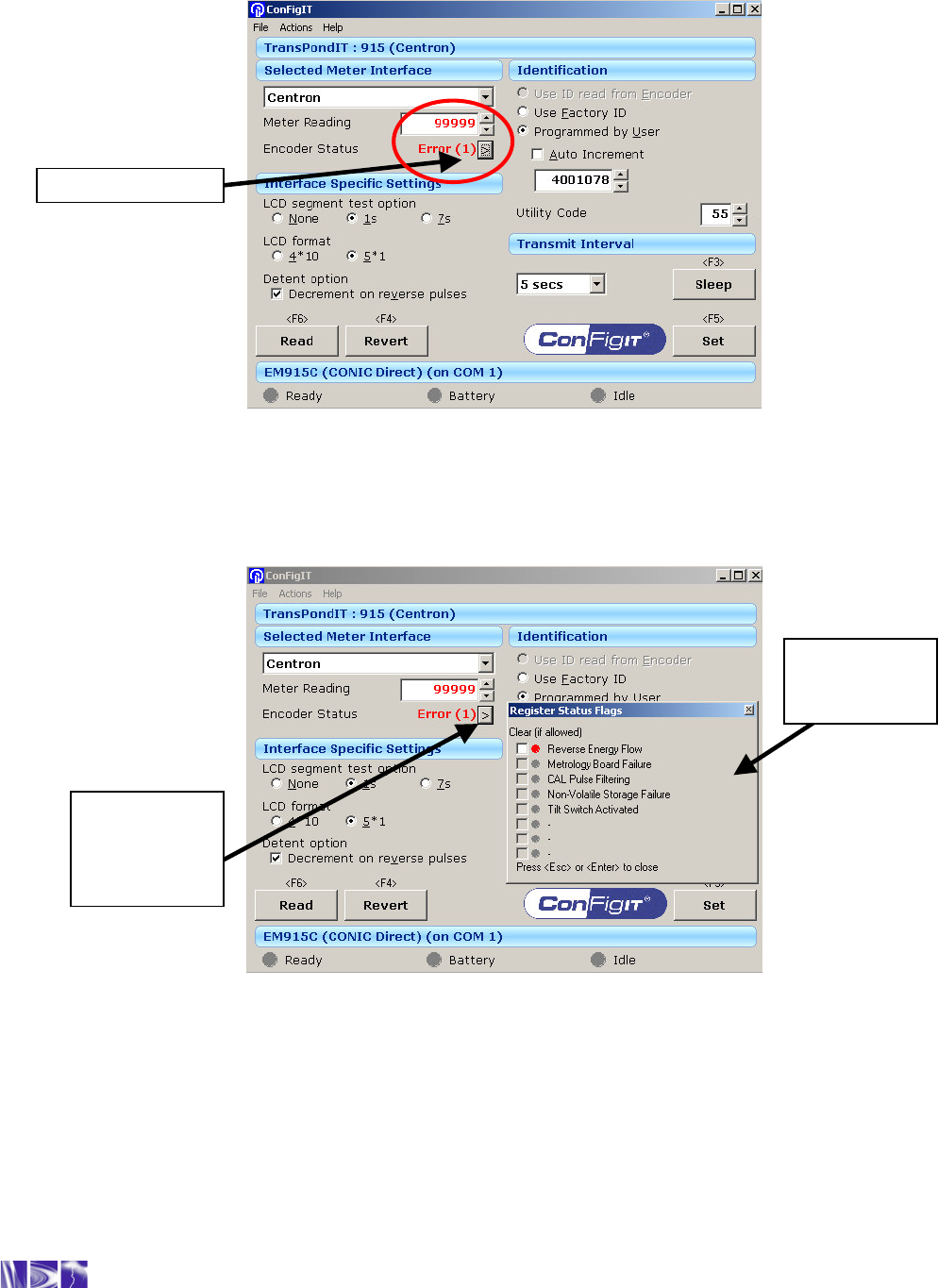
• A non-zero status code is highlighted in red alongside the word Error (see Figure 19).
• Clicking on the ‘>’ sign next to the “error code” window on the ConFigIT software
brings up the Register Status flags window for explanation (see Figure 20).
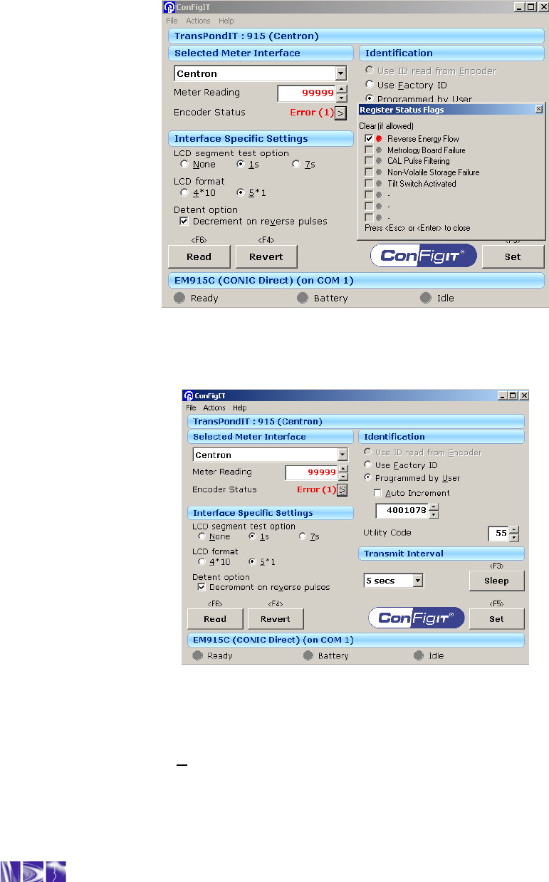
• The appropriate status flags are selected for clearing (see Figure 21).
• Once all changes are made, pressing ‘Set’ or <F5> stores the new configuration in the
TransPondIT.
Figure 18: Location of status code – (0) indicates normal operation
Figure 19 illustrates an example of the ConFigIT screen with a TransPondIT that has
registered a ‘reverse energy flow’. The ‘Meter Reading’ is also highlighted in red.
Status code
Technical Reference Manual - TransPondIT for CENTRON Electric Meter
20
Figure 19: ‘Reverse energy flow’ reported
Figure 20: Display Register Status Flag window
5.2.1 Clear a Status Code
1) Click on the ‘>’ sign (see Figure 20)
2) The ‘Register Status Flags’ window is displayed.
3) Click in the white box(s), tick mark(s) should appear (see Figure 21).
Status code = 1
Click on ‘>’ to
display the
Register
Status Flags
Register
Status Flags
window
Technical Reference Manual - TransPondIT for CENTRON Electric Meter
21
4) Press the ‘Enter’ or ‘Esc’ key to close the window.
5) The screen changes as shown in Figure 22
Figure 21: Select ‘Reverse Energy Flow’ status for clearing
Figure 22: TransPondIT Configuration Screen
6) Make any necessary changes required (e.g. meter reading, transmit interval).
7) Select Set or <F5>. This writes the new values and reads numbers back for
confirmation (see Figure 23).
8) Confirm that the status code is reset to (0). (see Figure 23)
Technical Reference Manual - TransPondIT for CENTRON Electric Meter
22
Figure 23: Reset status code
Technical Reference Manual - TransPondIT for CENTRON Electric Meter
23
5.2.2 Troubleshooting – General
Due to the modular design of the CENTRON meter, TransPondITs of similar voltage (120V or
240V) can be interchanged. Therefore, a suspect TransPondIT can be placed onto a working
base to verify proper operation of the TransPondIT.
Similarly, a known good TransPondIT can be placed on the base of a suspect meter to verify
proper operation of the base.
Alternatively, swap out the suspect meter with a known good meter.
Check whether correct voltage TransPondIT fitted – ie:
o 120V variant TransPondIT in a Form 2S socket
TransPondIT will appear to work correctly but will have reduced life – not
recommended.
o 240V variant TransPondIT in a Form 1S socket
TransPondIT may appear to work but stop working (and metering) if voltage falls
marginally life – not recommended.
5.2.3 Troubleshooting - Configuration
The first test to perform is to connect the PC to the ConFigIT (standard 9-way straight through
female connectors) and the ConFigIT to the TransPondIT. Run the ConFigIT application
ensuring that the communications port is set-up correctly. Select ‘Read’ or ‘<F6>’ and the LCD
should power up. If it doesn’t, check that the batteries in the ConFigIT are good (if applicable)
and also try a different ConFigIT to TransPondIT lead. If the LCD still fails to illuminate, then
refer to table 3.
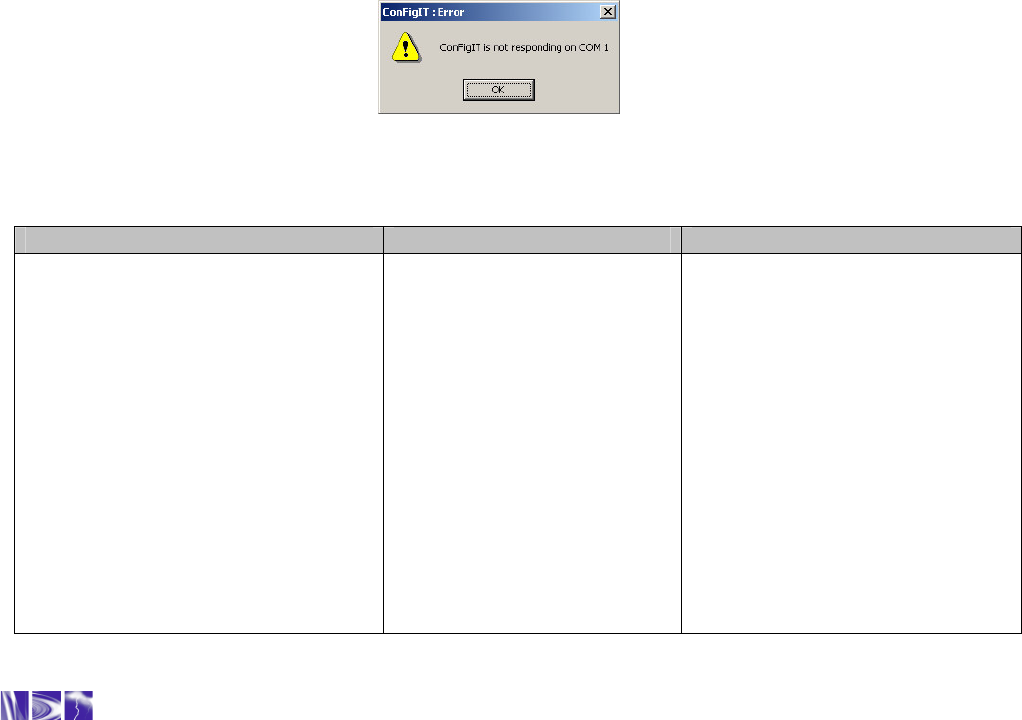
Figure 24: ConFigIT communications error message
ConFigIT Hardware Possible Cause(s): Actions:
Any of:
Message: ConFigIT is not
responding on Com 1 (see fig 24)
On/Standby LED is not illuminated
when ‘Read’ command sent.
On/Standby LED permanently on &
Any of:
ConFigIT batteries faulty or
ConFigIT DC Power Supply
not present.
TransPondIT not connected
to ConFigIT (possibly
caused by ConFigIT
connector not pushed fully
into the LCD recess).
ConFigIT PC Software is
Try the following:
Replace the batteries / check
the DC supply
Ensure connector is fully
inserted. Should hear a ‘click’.
Ensure the correct COM port is

Technical Reference Manual - TransPondIT for CENTRON Electric Meter
24
Computer / TransPondIT LEDs
flash
not configured to use the
correct COM port.
ConFigIT PC software in
conflict for a COM port with
another application (eg
Sync Monitor for PDA)
‘Computer’ serial cable
damaged
TransPondIT serial cable
damaged
ConFigIT internal fault
TransPondIT internal fault
selected for the hardware
connection, then use the drop
down menu File – Interface to
select the correct port.
Stop any application that is
using the same COM port as
ConFigIT
Try a different cable
Try a different cable
Call RAMAR for assistance
Call RAMAR for assistance
Blank Display on meter ConFigIT connector not
pushed fully into the LCD
recess
LCD / LCD driver failure
Loose power supply
connection
Ensure the connector is fully
inserted when configuring
Replace TransPondIT
Remove and re-seat the board-
to-board connector
ConFigIT Software
Software installs but is ‘locked’ Need product
activation code Send vcf file to RAMAR to
receive a new code
Configuration: Possible Cause(s): Action(s):
LCD does not display the segment
check TransPondIT is configured
not to display the segment
check
Reconfigure the TransPondIT
LCD only displays 4 digits TransPondIT is configured
to display in 4*10 format Reconfigure the unit LCD format
to 5*1
No radio reading Transmit Interval is OFF Reconfigure TransPondIT
transmit interval. Check COMMs
with HandTrackIT. If COMMs
fails then contact RAMAR
Table 3: ConFigIT Troubleshooting Chart

Technical Reference Manual - TransPondIT for CENTRON Electric Meter
25
APPENDIX A: METER COMPATIBILITY CHART & PART
NUMBERS
The TransPondIT for CENTRON is compatible with the following CENTRON meters
.
Form 1S 2S 2S 3S 3S 4S 12S
Volts 120V 240V 240V 120V 240V 240V 120V
Class 100 200 320 20 20 20 200
Part No (no
tilt switch): 915-120-01
915-122-01
915-122-01
915-120-01
915-122-01
915-122-01
915-120-01
Part No
(with tilt
switch):
915-121-01
915-123-01
915-123-01
915-121-01
915-123-01
915-123-01
915-121-01
**Qualification is pending on some meter forms
Table A-1: Meter compatibility chart

Technical Reference Manual - TransPondIT for CENTRON Electric Meter
26
APPENDIX B: TRANSPONDIT STATUS CODES
Status Code Description
0 No errors
1 Reverse Energy Flow detected
2 Metrology Board Failure
3 Reverse Energy Flow detected + Metrology Board Failure
4 CAL Pulse Filtering
5 CAL Pulse Filtering + Reverse Energy Flow
6 CAL Pulse Filtering + Metrology Board Failure
7 CAL Pulse Filtering + Reverse Energy Flow + Metrology Board Failure
8 Non-Volatile Storage Failure
9 Reverse Energy Flow detected + Non-Volatile Storage Failure
10 Metrology Board Failure + Non-Volatile Storage Failure
11 Reverse Energy Flow detected + Metrology Board Failure + Non-Volatile Storage Failure
12 CAL Pulse Filtering + Non-Volatile Storage Failure
13 CAL Pulse Filtering + Reverse Energy Flow + Non-Volatile Storage Failure
14 CAL Pulse Filtering + Metrology Board Failure + Non-Volatile Storage Failure
15 CAL Pulse Filtering + Reverse Energy Flow+ Metrology Board Failure + Non-Volatile
Storage Failure
16 Tilt Switch Activated
17 Tilt Switch Activated + Reverse Energy Flow detected
18 Tilt Switch Activated + Metrology Board Failure
19 Tilt Switch Activated + Reverse Energy Flow detected + Metrology Board Failure
20 Tilt Switch Activated + CAL Pulse Filtering
21 Tilt Switch Activated + CAL Pulse Filtering + Reverse Energy Flow
22 Tilt Switch Activated + CAL Pulse Filtering + Metrology Board Failure
23 Tilt Switch Activated + CAL Pulse Filtering + Reverse Energy Flow + Metrology Board
Failure
24 Tilt Switch Activated + Non-Volatile Storage Failure
25 Tilt Switch Activated + Reverse Energy Flow + Non-Volatile Storage Failure
26 Tilt Switch Activated + Metrology Board Failure + Non-Volatile Storage Failure
27 Tilt Switch Activated + Reverse Energy Flow + Metrology Board Failure + Non-Volatile
Storage Failure
28 Tilt Switch Activated + CAL Pulse Filtering + Non-Volatile Storage Failure
29 Tilt Switch Activated + CAL Pulse Filtering + Reverse Energy Flow + Non-Volatile Storage
Failure
30 Tilt Switch Activated + CAL Pulse Filtering + Metrology Board Failure + Non-Volatile Storage
Failure
31 Tilt Switch Activated + CAL Pulse Filtering + Reverse Energy Flow + Metrology Board
Failure + Non-Volatile Storage Failure
Table B-1: TransPondIT status codes
Note: If a Non-Volatile Storage Failure occurs, then subsequent Metrology, CAL or Reverse Direction
errors will not be reported. Therefore an error code of 10 indicates that the metrology board failed first
and then the NVRAM in that order.
Technical Reference Manual - TransPondIT for CENTRON Electric Meter
27
APPENDIX C: STATUS CODE TROUBLESHOOTING
It is expected that all of these troubleshooting operations are performed in the meter shop – after the
meter is withdrawn.
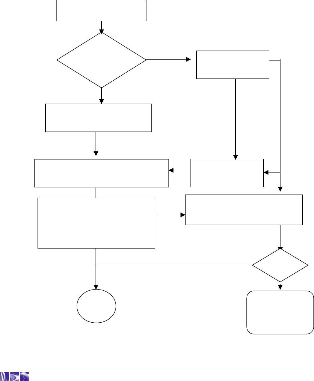
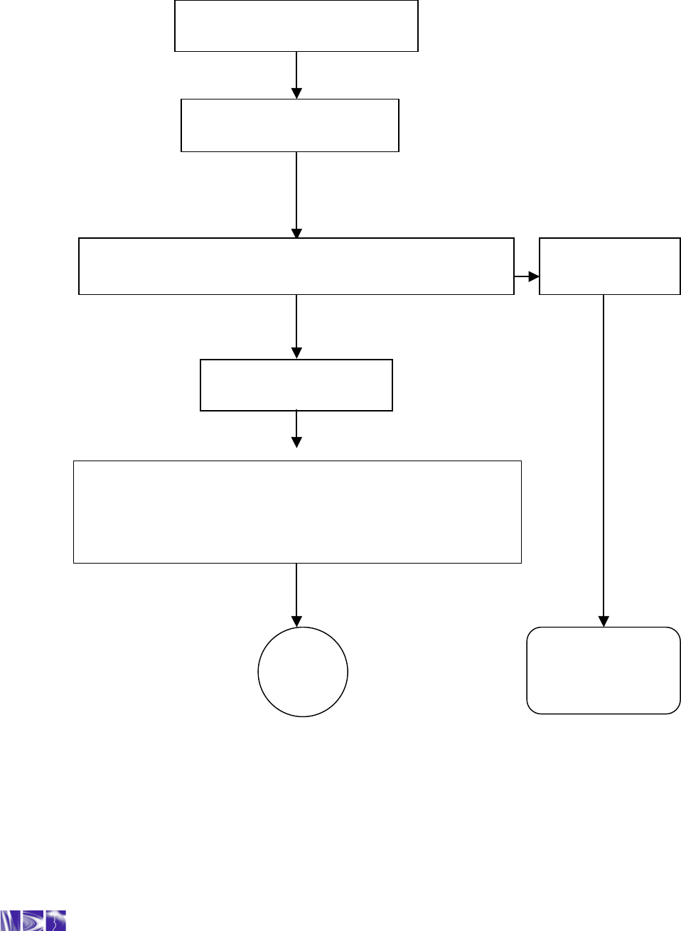
Figure C-1 Reverse energy flow
Note: the reverse energy flow flag is for information purposes. It does not mean that the TransPondIT is faulty.
Was the meter
fitted upside
down?
Follow utility procedures for
removing and re-
fitting meter in the
correct orientation
If appropriate, clear the status code and
check that TransPondIT is counting correctly.
Refer to chapters 3 & 5
END
Report finding to
appropriate utility
personnel
Call RAMAR
Technical
Support
1-888-987-2627
YES
NO
NO
YES
YES
NO
Reverse Energy Flow
[01]
Confirm metrology board function by
substituting another TransPondIT and
checking for correct operation.
Working
OK?
YES
Is there any physical
damage?
NO
Confirm correct operation of the meter.
(i.e. Meter reading increments. LCD
reading and radio reading are as set
by configuration). Note: If the LCD is
configured for 4*10, then the radio
reading will be 10x greater
Technical Reference Manual - TransPondIT for CENTRON Electric Meter
28
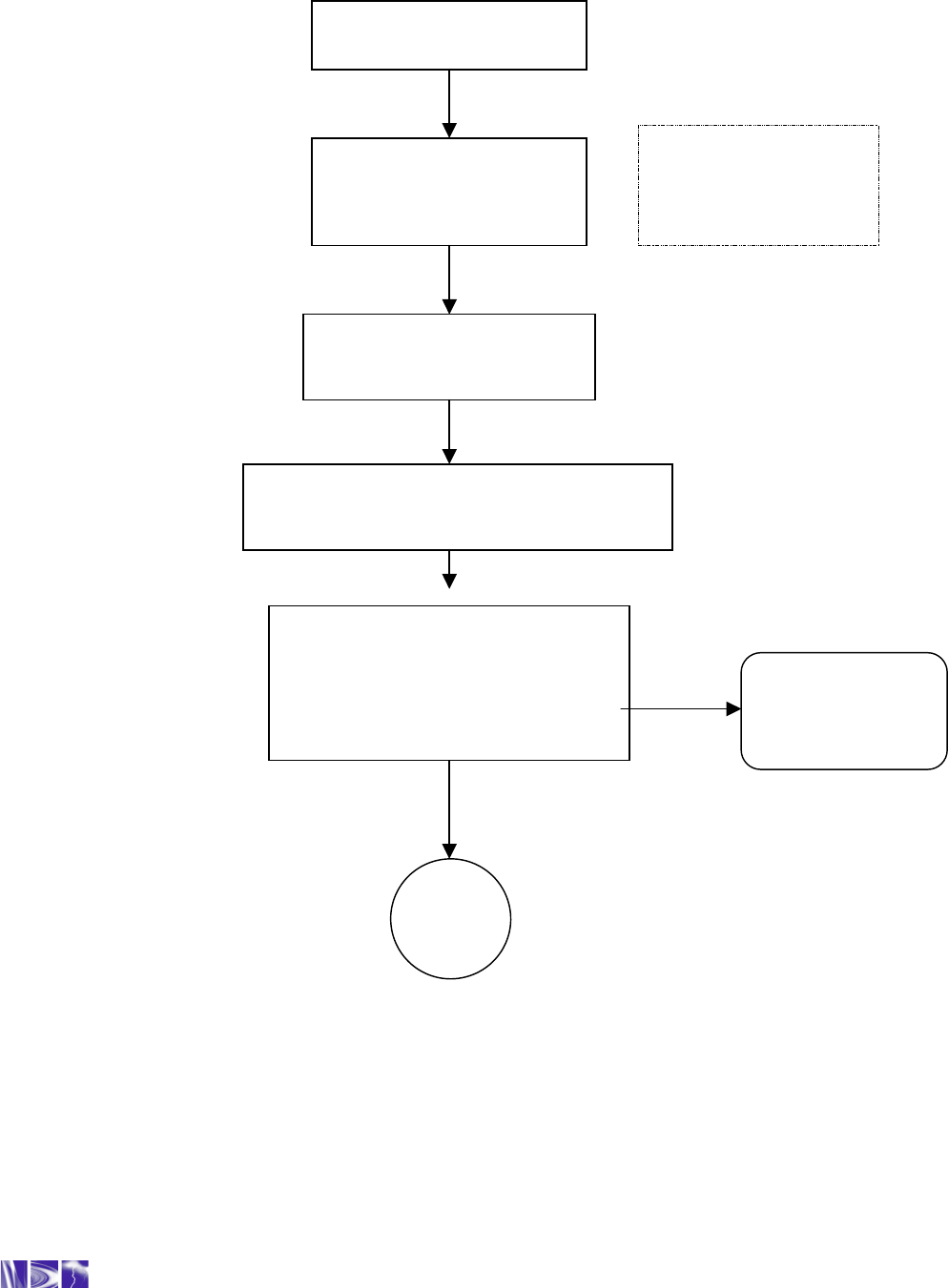
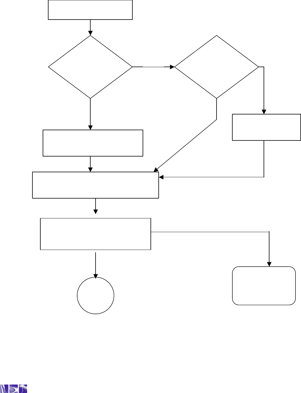
Figure C-2 Reverse meteorology board error
Metrology Board Error
[02]
TransPondIT is operating
correctly (i.e. LCD and radio
readings are identical and
non-zero)
Follow utility procedures for
swapping out meter base and
fit TransPondIT to new meter
Using ConFigIT clear the status code and
check that TransPondIT is counting correctly.
Refer to Chapters 3 and 5.
Call RAMAR
Technical
Support
1
-
888
-
987
-
2627
END
NO
YES
Note: If the LCD
format is 4*10, then
the radio reading will
be 10x greater
Confirm correct operation of the meter.
(i.e. Meter reading increments. LCD
reading and radio reading are as set
by configuration). Note: If the LCD is
configured for 4*10, then the radio
reading will be 10x greater

Technical Reference Manual - TransPondIT for CENTRON Electric Meter
29
CAL Filtering [04]
This status code is displayed when the TransPondIT records an instantaneous event of signals counted from the
metrology board at a rate > 32 per second – this corresponds to >115kW .
This is NOT a TransPondIT fault.
It is for information purposes only.
Report this event to the appropriate utility personnel.
Refer to the CENTRON Meter Technical Reference Guide for more information on the meter.
Technical Reference Manual - TransPondIT for CENTRON Electric Meter
30
Figure C-3 NVRAM failure
Call RAMAR
Technical
Support
1
-
888
-
987
-
2627
END
Non Volatile Memory Fault
[08]
TransPondIT is faulty
Replace
Fit a new TransPondIT into the existing or new meter base.
Configure the TransPondIT as required. (See chapters 3 & 5)
Install new meter at
customer site
Return faulty
TransPondIT to
RAMAR
Confirm correct operation of the meter.
(i.e. Meter reading increments. LCD reading and radio reading are
as set by configuration). Note: If the LCD is configured for 4*10,
then the radio reading will be 10x greater
Technical Reference Manual - TransPondIT for CENTRON Electric Meter
31
Tilt Switch Activated
[16]
Is the meter fitted
upside down?
Follow utility procedures for
removing and re-
fitting meter in the
correct orientation. Report findings
Using ConFigIT clear the status code and
check that TransPondIT is coun
ting correctly.
Refer to chapters 3 & 5
END
Is there any
obvious
physical
damage?
Report finding to
appropriate utility
personnel
Call RAMAR
Technical
Support
1-888-987-2627
YES
NO
NO
YES
YES
NO
Figure C-4: Tilt switch
Confirm correct operation of the meter.
(i.e. Meter reading increments. LCD
reading and radio reading are as set
by configuration). Note: If the LCD is

Technical Reference Manual - TransPondIT for CENTRON Electric Meter
32
APPENDIX D: COMMERCIAL HEALTH AND SAFETY
INFORMATION
WARRANTY DISCLAIMER
To the maximum extent permitted by applicable law, AT RAMAR LLC disclaim all other
warranties, expressed or implied, including, but not limited to implied warranties of
merchantability and fitness for a particular purpose, with regard to the hardware, the
accompanying written material, and the accompanying software.
To the maximum extent permitted by applicable laws, in no event shall AT RAMAR LLC be
held liable for damages whatsoever (including without limitation, special, incidental,
consequential, or indirect damages for personal injury, loss of business profits, business
interruption, loss of business information, or any other pecuniary loss) arising out of the use of
or inability to use this product, even if AT RAMAR LLC has been advised of the possibility of
such damages. In any case, AT RAMAR LLC’s entire liability under any provision of this
agreement shall be limited to what is specified in the warranty agreement signed by our
distributors.
SOFTWARE RIGHTS AND RESTRICTIONS
The software product and documentation are provided with restrictive rights. The software may
not be duplicated, reverse engineered, decompiled, disassembled or modified. The software
product and accompanying written material is protected by copyright laws and international
copyright treaties, as well as other intellectual property laws and treaties. The software
product is licensed, not sold.
SAFETY WARNING
Separate the electric meter from the power mains before removing the outer and inner
covers.
The TransPondIT unit is not serviceable by user except by the ConFigIT. Modifying the
TransPondIT voids the warranty and may result in the user paying for all costs normally
covered under warranty. For safety reasons, do not modify the unit from its original usage. If
the unit is defective please refer to the warranty for disposition or call RAMAR customer
service. Under no circumstances should the customer attempt to repair the TransPondIT.
WARRANTY WARNINGS
• Changes or modifications to software, receiver or transmitter equipment not expressly
approved by RAMAR could void the user’s authority to operate the equipment.
• The equipment must be professionally installed.
• The TransPondIT is solely industrial and commercial in design; therefore it cannot be
sold to the general public.

Technical Reference Manual - TransPondIT for CENTRON Electric Meter
33
COMPLIANCE WITH FCC REGULATIONS
FCC Part 15, Class B
This equipment has been tested and found to comply with the limits for a Class B digital device,
pursuant to Part 15 of the FCC Rules. These limits are designed to provide reasonable protection
against harmful interference in a residential installation. This equipment generates uses and can
radiate radio frequency energy and, if not installed and used in accordance with the instructions, may
cause harmful interference to other radio communications. However, there is no guarantee that
interference will not occur in a particular installation. If this equipment does cause harmful
interference to radio or television reception, which can be determined by turning the equipment off and
on, the user is encouraged to correct the interference by one or more of the following measures:
•
Reorient or relocate the affected receiving antenna.
•
Increase the separation between the equipment and affected receiver.
•
Connect the equipment to an outlet on a circuit different from that to which the affected
receiver is connected.
•
Consult an experienced radio/TV technician for help.
THIS DEVICE COMPLIES WITH PART 15 OF THE FCC RULES. OPERATION IS SUBJECT TO
THE FOLLOWING TWO CONDITIONS: (1) THIS DEVICE MAY NOT CAUSE HARMFUL
INTERFERENCE AND, (2) THIS DEVICE MUST ACCEPT ANY INTERFERENCE RECEIVED,
INCLUDING INTERFERENCE THAT MAY CAUSE UNDESIRED OPERATION.
COMPLIANCE WITH INDUSTRY CANADA REGULATIONS
The TransPondIT has been certified by Industry Canada (IC) as a low power device operable in the
license exempt radio frequency band as stated in document number RSS210.
RSS210 Low Power License-Exempt Radio Communications Devices (902 – 928MHz).
OPERATION IS SUBJECT TO THE FOLLOWING TWO CONDITIONS: (1) THIS DEVICE MAY NOT
CAUSE INTERFERENCE, AND (2) THIS DEVICE MUST ACCEPT ANY INTERFERENCE,
INCLUDING INTERFERENCE THAT MAY CAUSE UNDESIRED OPERATION OF THE DEVICE
This Class B digital apparatus meets the requirement of the Canadian Interference-Causing
Equipment Regulations.

Technical Reference Manual - TransPondIT for CENTRON Electric Meter
34
MODIFICATIONS TO TRANSPONDIT
Changes or modifications not expressly approved by AT RAMAR could void the user’s authority to
operate the equipment.
REPAIR OF TRANSPONDITS
There are no serviceable parts in the TransPondIT. All repairs require the unit to be returned to either
the distributor or RAMAR, depending on where the product was purchased. The standard warranty is
12 months from installation or 18 months from delivery? Contact RAMAR for proper return materials
authorization procedures.
Service return address:
RAMAR
511 Davis Drive
Suite 200,
Durham, North Carolina 27713
United States
Tel: 1-888.98.RAMAR (72627)
Fax: 919.991.9946
Legal
© 2004 AT RAMAR LLC. All rights reserved.
RAMAR, the AT RAMAR LLC logo, TransPondIT, ConFigIT, HandTrackIT, RAMIC, FastTrackIT and CellTrackIT are
trademarks or registered trademarks of Advanced Technology RAMAR Limited in the United States and/or other countries.
All other company names, brand names, and product names are the property of their respective holder(s). AT RAMAR LLC is
an Agent for Advanced Technology RAMAR Limited. RAMAR constantly enhances products and reserves the right to change
specifications or other product information without notice. This publication could include technical inaccuracies or
typographical errors. July 2004.
CENTRON, is a registered trademark of Itron (formerly Schlumberger Electricity, Inc.)