Blue Tower Communications EM915V1 EM TransPondIT Meter Interface Unit User Manual EM915 manual
Blue Tower Communications Ltd EM TransPondIT Meter Interface Unit EM915 manual
Manual
Part No. 950005501 IP 0A
Meter Shop Processes Page 1 of 20
© Advanced Technology RAMAR Ltd Company Confidential
Company Confidential
EM 915 V1.0
Manual
Prepared by: JSteenson ............................. ............................................……….
Signature Date
Approved by: .............................................. ............................................……….
Signature Date
This is an unpublished work the copyright in which vests in Advanced Technology RAMAR Ltd. All rights reserved.
The information contained herein is the property of Advanced Technology RAMAR Ltd. and is supplied without liability for
errors or omissions. No part may be reproduced or used except as authorised by contract or other written permission.
Part No. xxxxxxxx XX xx Document Title
Meter Shop Processes Page 2 of 20
© Advanced Technology RAMAR Ltd Company Confidential
DOCUMENT HISTORY
Rev CR-N No Action Originator Date
REFERENCED DOCUMENTS
Document Title Part No. Doc Type
Advanced Technology RAMAR Ltd
7 Enterprise Way
Aviation Park
Christchurch
Dorset
England
BH23 6HB
Tel: +44 (0)1202 592000
Fax: +44 (0)1202 592001
E-mail: info@atr-group.com

Part No. xxxxxxxx XX xx Document Title
Meter Shop Processes Page 3 of 20
© Advanced Technology RAMAR Ltd Company Confidential
GLOSSARY
AMR Automatic Meter Reading
BOM Bill of Materials
EIRP Effective Isotropic Radiated Power
EM Electricity Meter
HALT Highly Accelerated Life Test
IC Integrated Circuit
ISM Instrumentation, Scientific & Medical
IT Information Technology
MIU Meter Interface Unit
PIC Programmable Intelligent Controller
ppm Parts per million
PSR Packet Success Rate
RF Radio Frequency
ROI Return On Investment
TBD To Be Determined
UK United Kingdom
US United States of America

TABLE OF CONTENTS
1. Introduction ..........................................................................................................................................5
1.1. General ..............................................................................................................................................5
1.2. Scope.................................................................................................................................................5
2. Product description .............................................................................................................................6
2.1. Ease of Installation.............................................................................................................................6
3. Environmental Specifications .............................................................................................................7
3.1. Storage Temperature Range..............................................................................................................7
3.2. Operational Temperature Range........................................................................................................7
3.3. Humidity.............................................................................................................................................7
3.4. Shock.................................................................................................................................................7
3.5. Vibration.............................................................................................................................................7
4. Mechanical Specifications...................................................................................................................8
4.1. Construction.......................................................................................................................................8
4.2. Packaging ..........................................................................................................................................8
4.3. Marking ..............................................................................................................................................9
5. Electrical Specifications ....................................................................................................................10
5.1. Compatibility ....................................................................................................................................10
5.2. Power Supply...................................................................................................................................11
5.3. Pick-Up ............................................................................................................................................12
5.3.1. MECHANISM ..........................................................................................................................12
5.3.2. ACCURACY ...........................................................................................................................12
5.3.3. TAMPER DETECTION ..............................................................................................................12
5.4. Radio ...............................................................................................................................................13
5.4.1. TRANSMIT CARRIER FREQUENCY ............................................................................................13
5.4.2. ANTENNA ..............................................................................................................................13
5.4.3. TRANSMISSION INTERVAL .......................................................................................................13
6. Interface specifications .....................................................................................................................14
6.1. Meter Interfaces ...............................................................................................................................14
6.1.1. POWER.................................................................................................................................14
6.2. ConFigIT Interface ...........................................................................................................................14
6.2.1. HARDWARE ...........................................................................................................................14
6.2.2. USE......................................................................................................................................14
7. Regulatory Compliance .....................................................................................................................15
7.1. System Integration ...........................................................................................................................16
7.2. Meter Compatibility ..........................................................................................................................16
8. Overview .............................................................................................................................................17
8.1. Production Process Flow .................................................................................................................17
8.1.1. THE FOLLOWING PROCESS FLOW CHART SHOWS THE EXPECTED ROUTE TO ACHIEVE THE
INSTALLING, TESTING AND CONFIGURING SEQUENCE OF THE EM MIU INTO VARIOUS RETROFIT METERS: .......17
8.2 METER PREPARATION................................................................................................................18
8.2.1 ALL RECEIVED METERS ARE TO HAVE THEIR SERIAL NUMBERS RECORDED AS PER EXISTING
PROCEDURES.........................................................................................................................................18
8.3 DISK MARKING ..........................................................................................................................19
Part No. xxxxxxxx XX xx Document Title
Meter Shop Processes Page 5 of 20
© Advanced Technology RAMAR Ltd Company Confidential
1. INTRODUCTION
1.1. General
This document is intended to provide detailed information required by an AMR
Meter Shop for the integration of AT RAMAR’s 900 series Electric Meter (EM)
TransPondIT Meter Interface Unit (MIU) product for single phase domestic
electricity meters in the US.
1.2. Scope
This document describes the 900 series EM TransPondIT MIU and provides the
necessary level of detail to enable the meter shop to install, test and deliver the
product ready for use by the customer.

Part No. xxxxxxxx XX xx Document Title
Meter Shop Processes Page 6 of 20
© Advanced Technology RAMAR Ltd Company Confidential
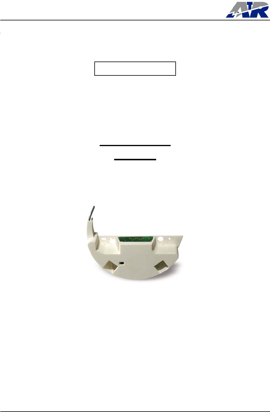
2. PRODUCT DESCRIPTION
TransPondIT allows the utility to receive data from its meters remotely. The
TransPondIT collects data from the meter and transmits it to a data collection device,
which may be mobile or fixed. In addition, the TransPondIT is capable of detecting
reverse rotation and will transmit an alarm indication if there is doubt about the
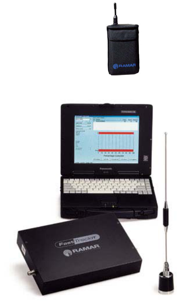
validity of the reading. The TransPondIT can be read by the following RAMAR
products: HandTrackIT, FastTrackIT, or CellTrackIT with no change to the
TransPondIT.
The TransPondIT can be fitted or retro-fitted in minutes to the meter.
Only qualified and properly trained personnel should attempt the installation of the
EM MIU.
2.1. Ease of Installation
EM MIU units will be installed in two different settings; either with new meters at the
meter manufacturer’s plant or in approved meter shops that rework and calibrate
existing meters. It is a design criteria that the MIU be capable of being mounted in
a meter at point of meter calibration without additional tests other than ConFigIT to
confirm PSU connection and to load mechanical register data into electronic
register.
Mounting of the MIU in the meter takes similar time to that of mounting the lower
faceplate plus some time for connection of the power wires.
Mounting of the EM MIU within the electricity meter is simple with minimal operator
training required assuring proper installation and configuration settings by meter
shop employees or field personnel. Field personnel perform configuration of
account numbers at the end-user’s site with the EM ConFigIT device.
Clearing of tamper register in field is performed using ConFigIT.
Caution:
Changes or modifications not expressly approved by Advanced Technology
RAMAR Ltd could void the user’s authority to operate the equipment.

Part No. xxxxxxxx XX xx Document Title
Meter Shop Processes Page 7 of 20
© Advanced Technology RAMAR Ltd Company Confidential
3. ENVIRONMENTAL SPECIFICATIONS
3.1. Storage Temperature Range
The temperature range for long-term storage of the MIU in un-powered state is to be -10ºC
to +50ºC.
The temperature range allowed for transport of the MIU in un-powered state is between
-40ºC to +85ºC.
Note: The MIU should not be held in the extended temperature range for transport for
more than 30 days.
3.2. Operational Temperature Range
The operational temperature range of the MIU shall be -40ºC to +50ºC with occasional
excursions to +85ºC.
3.3. Humidity
The non-condensing relative humidity shall be 5% to 95%.
3.4. Shock
The MIU when mounted in meter is to survive Transportation drop test – ISTA Test
Procedure 1A
3.5. Vibration
The MIU when mounted in meter is to survive Transportation Vibration test – ISTA Test
Procedure 1A.
4. MECHANICAL SPECIFICATIONS
4.1. Construction
The MIU is designed so that it fits all of the meter types listed with a minimal set of
adaptor hardware.
The product is fitted in the location of the meter lower faceplate, utilising the existing
mounting stand-offs.
The MIU is enclosed in a plastic enclosure to provide protection in handling and
against direct sunlight.
Torque specifications will be provided for attachment fixings to ensure a reliable
installation.
The design avoids any requirement for alignment of pickup at time of installation.
No meter calibration points are obscured.
4.2. Packaging
Packaging has been developed and tested to ensure that damage does not occur to
the product during normal freight handling. There shall be 48 or 96 units per
package.
Part No. xxxxxxxx XX xx Document Title
Meter Shop Processes Page 9 of 20
© Advanced Technology RAMAR Ltd Company Confidential
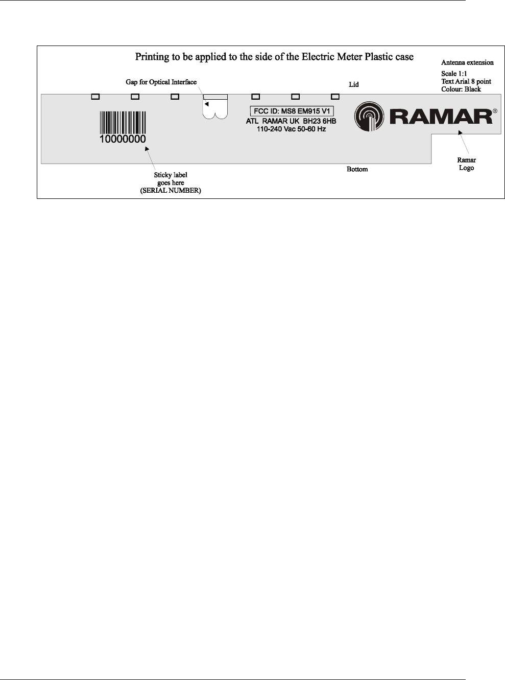
4.3. Marking
The MIU marking is to include:
• ATL RAMAR UK logo
• Part code
• FCC approval identifier
• Canadian approval identifier
• Serial number (with 128C bar code)
• Mains input voltage and frequency
5. ELECTRICAL SPECIFICATIONS
5.1. Compatibility
The unit operates in the same ISM band as the water TransPondIT products.
Furthermore, the EM is compatible with the following reading systems:
• HandTrackIT RR915/F-01-013 to RR915/F-01-04
• FastTrackIT FR915-01-01

Part No. xxxxxxxx XX xx Document Title
Meter Shop Processes Page 11 of 20
© Advanced Technology RAMAR Ltd Company Confidential
5.2. Power Supply
The unit takes mains power from the supply side of the meter.
No batteries are required.
The input voltage range over which the product must be able to read disk and send
transmissions is 100 – 260Vac.
Protection is provided so that the unit will survive the overvoltages and voltage
surges defined in ANSI C12.1.
There is no loss of configuration or meter reading data after power surge, brownout
or interrupt.
Power-line noise as defined in ANSI C12.1 does not adversely affect the unit.
The unit is appropriately protected to prevent the possibility of fire damage to a
residence.
Any hazardous voltage points have been protected to avoid accidental contact
during manufacture, service or calibration of the meter.
The average power consumption of the unit shall be less than 1.0W.
5.3. Measurement Technique
5.3.1. Mechanism
Electricity usage is measured by detecting rotation of the Ferraris disc. The
detection mechanism is frictionless and does not alter the balance of the disc.
The mechanism will restart regardless of disc position.
The detection mechanism will operate in ambient light levels of up to 100,000lux.
Reverse rotation is detected and causes the register to be decremented so that the
electronic register will match the mechanical register.
For meters where there is no suitable mark provided, the kit provided by the meter
shop shall include a mechanism for providing a black mark on disc that will not peel
off. The specifications of this mark are included in this document.
5.3.2. Accuracy
The electronic register is to reflect disc rotations to accuracy of better than 0.05%.
5.3.3. Tamper detection
The value in a tamper register shall be indicated in the following circumstances:
• if the circuit detects an internal fault
• if the sensor is disabled or
• if the rotation of the Ferraris disc is reversed (the design is to incorporate a
separate register to record reverse rotation).
Clearing of the tamper events is to be performed on site using ConFigIT.
5.4. Radio
Operational Range
The operational range is at least 300m in open field to a production HandTrackIT
held at height of 1.5m.
5.4.1. Transmit Carrier Frequency
The nominal transmission frequency shall be 919.8976MHz.
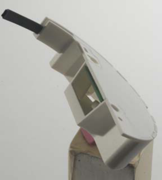
5.4.2. Antenna
The antenna is integral to the TransPondIT located within the glass case of the
electricity meter and does not hinder the installation of the product or obscure the
manually read dials, calibration screws or face-plate.
5.4.3. Transmission Interval
The transmit interval is configurable from 5 seconds to 10 hours.

Part No. xxxxxxxx XX xx Document Title
Meter Shop Processes Page 14 of 20
© Advanced Technology RAMAR Ltd Company Confidential
6. INTERFACE SPECIFICATIONS
6.1. Meter Interfaces
6.1.1. Power
Mains power input.
6.2. ConFigIT Interface
6.2.1. Hardware
The Electric TranspondIT MIU is interfaced to ConFigIT from outside the glass via a
bi-directional optical port that is active when the MIU is powered.
6.2.2. Use
a. In Meter Retrofit Shop or in Meter Factory
The following actions can be performed:
• Enter mechanical meter reading
• Enter rotation rate
• Enter utility code
b. At meter site
The following actions canl be performed:
• Customer number
• Clear tamper
• Readout of all registers including ID, all settings and status

7. REGULATORY COMPLIANCE
Fitting a meter with the MIU does not invalidate its compliance with the following:
a. ANSI C12.1 – 2001 American National Standard for Electric Meters
(covers performance aspects)
b. ANSI C12.10 – 1997 American National Standard for Watthour Meters
(covers environmental and physical aspects)
c. CFR47 Part 15 (Note – declared as Class B Digital Device), Part A General,
Part C Intentional Radiator
This device complies with Part 15 of the FCC Rules.
Operation is subject to the following conditions:
(1) This device may not cause harmful interference, and
(2) This device must accept any interference received, including interference that may cause undesired operation.
Note: This equipment has been tested and found to comply with the limits for
a Class B digital device, pursuant to Part 15 of the FCC Rules. These limits
are designed to provide reasonable protection against harmful interference in
a residential installation. This equipment generates, uses and can radiate
radio frequency energy and, if not installed and used in accordance with the
instructions, may cause harmful interference to radio or television reception,
which can be determined by turning the equipment on and off, the user is
encouraged to try to correct the interference by one or more of the following
measures:
--Reorient or relocate the receiving antenna
--Increase the separation between the equipment and receiver
--Consult the dealer
Part No. xxxxxxxx XX xx Document Title
Meter Shop Processes Page 16 of 20
© Advanced Technology RAMAR Ltd Company Confidential
7.1. System Integration
Installation Tools and techniques should consider methods such as bar-code scanners to
allow proper configuration and accuracy of information. Seamless integration into existing
IT systems is to be a design aim.
7.2. Meter Compatibility
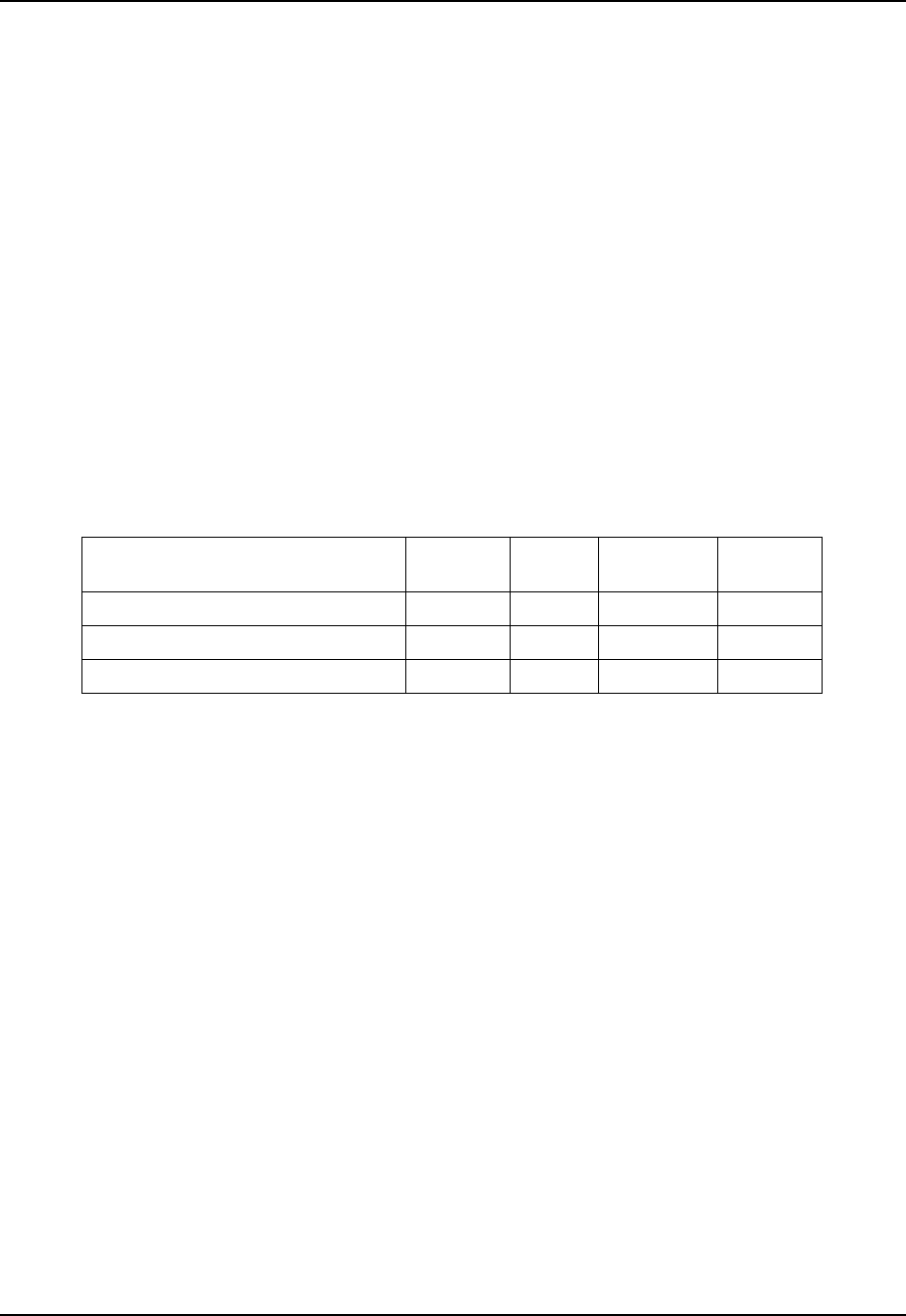
The EM MIU is compatible with electricity meters listed in Table 1.
Table 1. Compatibility includes all interfaces such as mechanical, electrical, magnetic and
optical.
Manufacturer Model
Number
Voltage Rotations
per kWH
Form
Factor
General Electric I-70-S/2 240Vac 7.2 2S
Siemens/Landis&Gyr MX 240Vac 7.2 2S
ABB AB1 240Vac 7.2 2S
Table 1: List of Compatible Electricity Meters

Part No. xxxxxxxx XX xx Document Title
Meter Shop Processes Page 17 of 20
© Advanced Technology RAMAR Ltd Company Confidential
8. OVERVIEW
8.1. Integration Process Flow
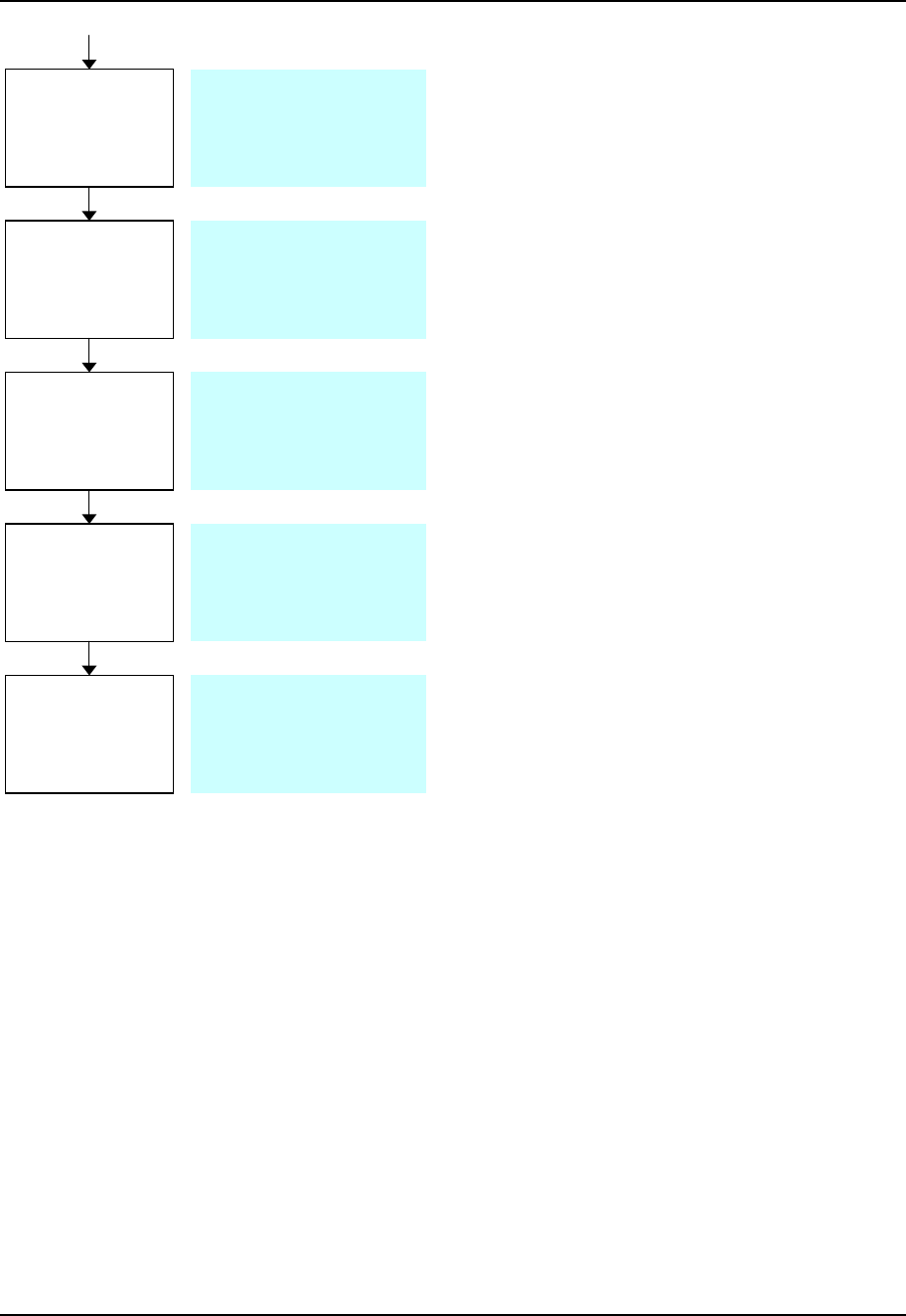
8.1.1. The following process flow chart shows the expected route to
achieve the installing, testing and configuring sequence of the EM MIU into
various retrofit meters:
Meters
Received
Modules
Shipped from
CEM/UK
Modules
Received
Prepare
meters
Clean Disk
and apply
Marker
Fit Potential
Clips
Select correct
Fixing Kit
Install Module
Cable Assembly – Parts to be sourced
by meter house.
A
TR to specify Molex connector.
Specific drawings/part numbers to be
available to ATR.
Paint/Decal marker to be
sourced by meter house
and spec’d by ATR.
Remove covers and
store.
Clean meters.
Inspect for damage, then
zero meter.
3 Meter Types – Meter House
to source longer screws per
type and pillars (L&G).
A
TR to spec pillar length.
Install with longer screws and pillars
(L&G only). Connect potential clips.
Refit meter nameplate.
Required tooling to be provided by
Meter House.
Palletised in multiples of
48/96.
Record Serial No.’s
Modules to be inspected
for damage to enclosure
and antenna.
Record Serial No.’s
Packaging to be
determined by ATR, in
quantities of 48/96 or
multiples of.
Part No. xxxxxxxx XX xx Document Title
Meter Shop Processes Page 18 of 20
© Advanced Technology RAMAR Ltd Company Confidential
8.2 Meter Preparation
8.2.1 All received meters are to have their serial numbers recorded as per existing
procedures.
8.2.2 Covers are to be removed, cleaned and stored.
8.2.3 Meters are to be inspected for any damage as per existing Meter House criteria.
Test and
Calibrate
Program
/Configure
Module
Record Test
Data
Box and
Palletise
Ship/Store
Test Spec to be defined
by ATR.
Meter test and
calibration procedure as
p
er Meter House s
p
ec.
Hand Held ConFigIT to
be supplied with spec
and procedures by ATR.
Software to be
compatible with Meter
House tracking database
– Information Required
Meters to be resealed.
Final Inspection.
Serial No.’s scanned.

Part No. xxxxxxxx XX xx Document Title
Meter Shop Processes Page 19 of 20
© Advanced Technology RAMAR Ltd Company Confidential
8.3 Disk Marking
8.3.1 The disk marking method will be determined by customer request, be it paint or
decal. It must meet the following criteria:
i) There is minimum of a 20mm width apparent at the optical centres.
(Suggested dimensions as per drawing 52000501 iss C)
ii) The material must have no magnetic susceptibility or effect.
iii) The material must have 99.98%, or greater, absorption of
electromagnetic radiation having a wavelength of between 300 and
1200nm (UV, visible and IR light).
8.3.2 The marking method used will be as per Meter House current procedures and must
ensure that no damage or stress is caused to the Ferraris Disk is any form.
8.4 EM MIU Installation
8.4.1 The EM MIU is to be installed to the various meter types, as per Table 1, using the
appropriate fixing kit as sourced by the Meter House.
8.4.2 The kit will consist of longer screws of the same thread size as the existing ones
used to mount the lower faceplate to the standoff pillars.
8.4.3 In the case of any meter type not having standoff pillars high enough to support the
EM MIU in its correct position (such as the L&G MX), additional pillars are to be
sourced and fitted (L&G MX pillars to be 20mm long).
8.4.4 The Meter House will source the cable assembly used to connect the EM MIU to
the bus-bar supply. Specification for the cable to board connector will be provided
by the ATR.
8.4.5 The Meter House shall supply tooling required to install the EM MIU.
8.5 Test and Calibration
8.5.1 EM MIU to be tested iaw Test specification and procedures supplied by ATR.
8.5.2 Meter to be calibrated as per Meter House procedures.

Part No. xxxxxxxx XX xx Document Title
Meter Shop Processes Page 20 of 20
© Advanced Technology RAMAR Ltd Company Confidential
8.6 Configuration
8.6.1 The EM MIU is to be configured using the handheld ConFigIT supplied with relevant
software and procedures by ATR.
8.6.2 The following steps are to be performed at the Meter House:
8.6.2.1 i) Clear Tamper
ii) Enter mechanical meter reading
iii) Enter rotation rate (as per Table 1)
iv) Enter utility code
8.7 Quality
8.7.1 The Meter House shall continue to work to their current quality specifications.
8.7.2 Specific standards/criteria shall be supplied by ATR if required.