Blue Tower Communications PTRANSPONDITV1 Water Meter Transmitter User Manual 295100

Blue Tower Communications Ltd Water Meter Transmitter 295100

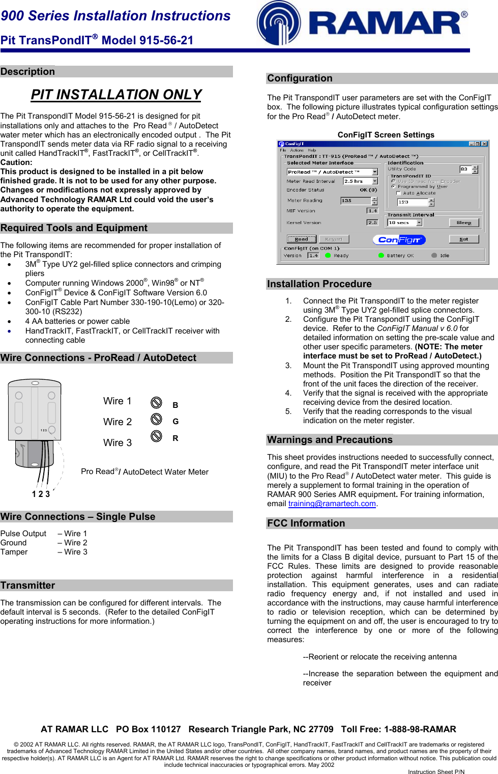
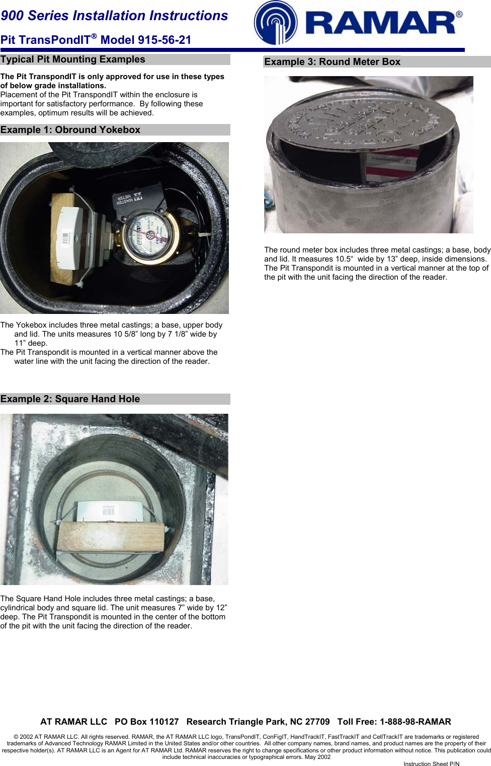
Users Manual Revised

900 Series Installation Instructions  Pit TransPondIT Model 915-56-21     AT RAMAR LLC   PO Box 110127   Research Triangle Park, NC 27709   Toll Free: 1-888-98-RAMAR  © 2002 AT RAMAR LLC. All rights reserved. RAMAR, the AT RAMAR LLC logo, TransPondIT, ConFigIT, HandTrackIT, FastTrackIT and CellTrackIT are trademarks or registered trademarks of Advanced Technology RAMAR Limited in the United States and/or other countries.  All other company names, brand names, and product names are the property of their respective holder(s). AT RAMAR LLC is an Agent for AT RAMAR Ltd. RAMAR reserves the right to change specifications or other product information without notice. This publication could include technical inaccuracies or typographical errors. May 2002   Instruction Sheet P/N    Description  PIT INSTALLATION ONLY  The Pit TranspondIT Model 915-56-21 is designed for pit installations only and attaches to the  Pro Read  / AutoDetect  water meter which has an electronically encoded output .  The Pit TranspondIT sends meter data via RF radio signal to a receiving unit called HandTrackIT®, FastTrackIT®, or CellTrackIT®. Caution: This product is designed to be installed in a pit below finished grade. It is not to be used for any other purpose. Changes or modifications not expressly approved by Advanced Technology RAMAR Ltd could void the user’s authority to operate the equipment.  Required Tools and Equipment  The following items are recommended for proper installation of the Pit TranspondIT: • 3M® Type UY2 gel-filled splice connectors and crimping pliers •  Computer running Windows 2000®, Win98® or NT® • ConFigIT® Device & ConFigIT Software Version 6.0 •  ConFigIT Cable Part Number 330-190-10(Lemo) or 320-300-10 (RS232) •  4 AA batteries or power cable • HandTrackIT, FastTrackIT, or CellTrackIT receiver with connecting cable  Wire Connections - ProRead / AutoDetect            Wire 1                    Wire 2           Wire 3   Pro Read/ AutoDetect Water Meter     Wire Connections – Single Pulse  Pulse Output   – Wire 1 Ground     – Wire 2 Tamper     – Wire 3    Transmitter  The transmission can be configured for different intervals.  The default interval is 5 seconds.  (Refer to the detailed ConFigIT operating instructions for more information.)           Configuration  The Pit TranspondIT user parameters are set with the ConFigIT box.  The following picture illustrates typical configuration settings for the Pro Read / AutoDetect meter.     ConFigIT Screen Settings    Installation Procedure  1.  Connect the Pit TranspondIT to the meter register using 3M® Type UY2 gel-filled splice connectors. 2.  Configure the Pit TranspondIT using the ConFigIT device.  Refer to the ConFigIT Manual v 6.0 for detailed information on setting the pre-scale value and other user specific parameters. (NOTE: The meter interface must be set to ProRead / AutoDetect.) 3.  Mount the Pit TranspondIT using approved mounting methods.  Position the Pit TranspondIT so that the front of the unit faces the direction of the receiver. 4.  Verify that the signal is received with the appropriate receiving device from the desired location. 5.  Verify that the reading corresponds to the visual indication on the meter register.  Warnings and Precautions  This sheet provides instructions needed to successfully connect, configure, and read the Pit TranspondIT meter interface unit (MIU) to the Pro Read / AutoDetect water meter.  This guide is merely a supplement to formal training in the operation of RAMAR 900 Series AMR equipment. For training information, email training@ramartech.com.  FCC Information  The Pit TranspondIT has been tested and found to comply with the limits for a Class B digital device, pursuant to Part 15 of the FCC Rules. These limits are designed to provide reasonable protection against harmful interference in a residential installation. This equipment generates, uses and can radiate radio frequency energy and, if not installed and used in accordance with the instructions, may cause harmful interference to radio or television reception, which can be determined by turning the equipment on and off, the user is encouraged to try to correct the interference by one or more of the following measures: --Reorient or relocate the receiving antenna --Increase the separation between the equipment and receiver     1 2 31 2 3GRB
900 Series Installation Instructions  Pit TransPondIT Model 915-56-21     AT RAMAR LLC   PO Box 110127   Research Triangle Park, NC 27709   Toll Free: 1-888-98-RAMAR  © 2002 AT RAMAR LLC. All rights reserved. RAMAR, the AT RAMAR LLC logo, TransPondIT, ConFigIT, HandTrackIT, FastTrackIT and CellTrackIT are trademarks or registered trademarks of Advanced Technology RAMAR Limited in the United States and/or other countries.  All other company names, brand names, and product names are the property of their respective holder(s). AT RAMAR LLC is an Agent for AT RAMAR Ltd. RAMAR reserves the right to change specifications or other product information without notice. This publication could include technical inaccuracies or typographical errors. May 2002   Instruction Sheet P/N   Typical Pit Mounting Examples  The Pit TranspondIT is only approved for use in these types of below grade installations. Placement of the Pit TranspondIT within the enclosure is important for satisfactory performance.  By following these examples, optimum results will be achieved.    Example 1: Obround Yokebox    The Yokebox includes three metal castings; a base, upper body and lid. The units measures 10 5/8” long by 7 1/8” wide by 11” deep. The Pit Transpondit is mounted in a vertical manner above the water line with the unit facing the direction of the reader.    Example 2: Square Hand Hole    The Square Hand Hole includes three metal castings; a base, cylindrical body and square lid. The unit measures 7” wide by 12” deep. The Pit Transpondit is mounted in the center of the bottom of the pit with the unit facing the direction of the reader.           Example 3: Round Meter Box    The round meter box includes three metal castings; a base, body and lid. It measures 10.5“  wide by 13” deep, inside dimensions. The Pit Transpondit is mounted in a vertical manner at the top of the pit with the unit facing the direction of the reader.

Navigation menu