Blum Novotest TCA Measuring Probe User Manual 306000011S EN V3
Blum Novotest GmbH Measuring Probe 306000011S EN V3
UserMan
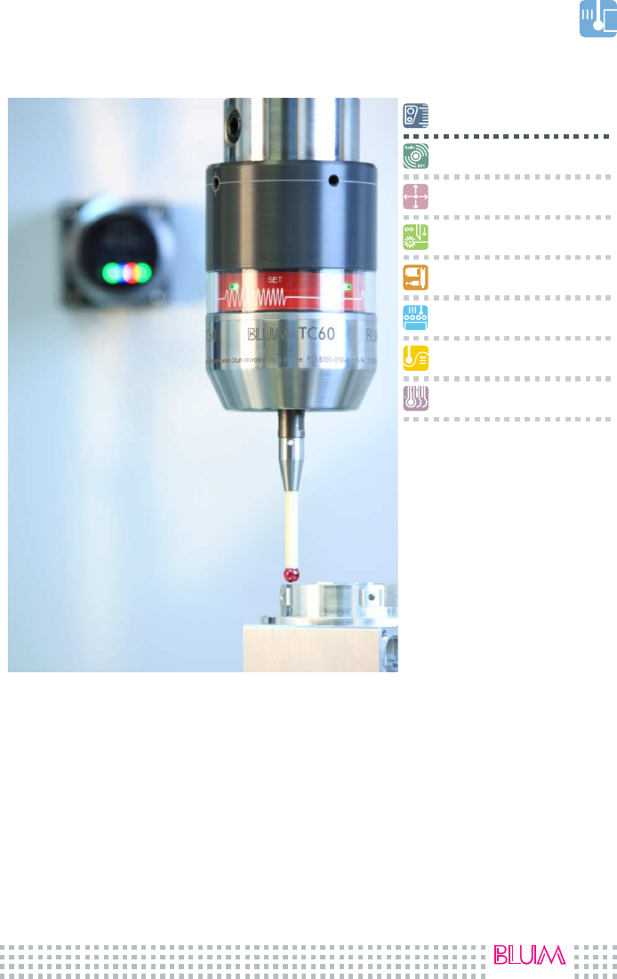
TC60 | TC63-30
Touch probe
focus on productivity
–
Workpiece measurement
Radio transmission
Multidirectional
Wear-free measuring mechanism
Modular system
Batch- & mass production
Contour measurement
Axes compensation
Operating instructions English
Type P03.6000-010 | P03.6300-010

by Blum-Novotest 2010
3
Content
1. Safety Rules .................................................. 4
2. System Overview .............................................. 5
2.1 Display Elements................................................................................................... 5
2.2 Tool Holder ............................................................................................................ 7
2.3 Technical Data ..................................................................................................... 8
2.4 Complete System................................................................................................. 9
3. Mounting and Commissioning ................................... 10
3.1 Batterie einsetzen / wechseln .......................................................................... 10
3.2 Mounting of the Tool Holder ............................................................................ 11
3.3 Mounting of the TC76-T ..................................................................................... 12
3.4 Mounting of the Stylus ....................................................................................... 13
3.5 Cranked Styli (TC63-30/TC76)........................................................................... 14
3.6 Display Basic Adjustments ................................................................................ 15
3.7 Programming of the Basic Adjustments ......................................................... 16
3.8 Probe Pairing....................................................................................................... 18
3.9 Switch-on Probe (via radio receiver) ............................................................. 18
4. Maintenance ................................................ 18
4.1 Cleaning of the transparent ring..................................................................... 18
4.2 Exchange of External Bellows .......................................................................... 19
5. Trouble Shooting ............................................. 21
6. Order Numbers .............................................. 22
7. Shipping Instructions / Storage .................................. 25
8. Radio Approval .............................................. 26
Installation instructions radio receiver RC66 (P03.6600-000.011)
Installation instructions interface IF59-A2 (P03.5900-000.011)
Programming instructions Blum measuring cycles (P03.8000-
031.305L/360L)
P03.6000-000.011S
306000011S_EN.docx
02.05.2011 version: V1A
Original operating instructions
Subject to technical change without any
notice
Safety Rules
4
by Blum-Novotest 2010
Zeichenerklärung:
CAUTION
Important advice for appliance protection
Advice to secondary literature
Additional advice
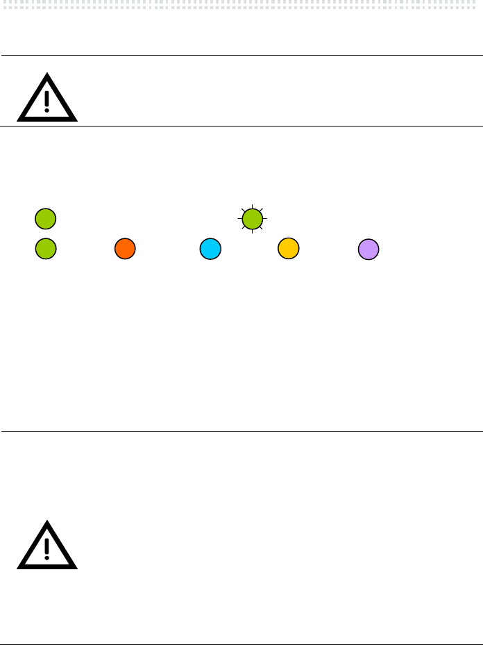
LED shines
LED flashes
Green Red Blue Orange Violet
Abbreviations:
BTH Blum Tool Holder
M
d
Tightening Torque
LF: Low Force
1. Safety Rules
CAUTION
Important advice for appliance protection:
• Handle probe like a precision tool.
• Keep the probe clean.
• Mount the probe in assigned tool holders only.
• Battery: Please insert before operating!
• Protect the probe by using programmed maximum travel.
• Ensure that adequate safety regulations as well as safety
interlockings are kept.
• Damaged styli are not reusable.
GN
GN
GN
VT
OG
BU
RD
System Overview
by Blum-Novotest 2010
5
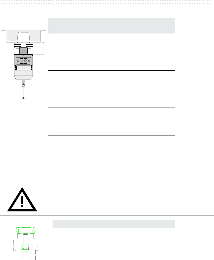
2. System Overview
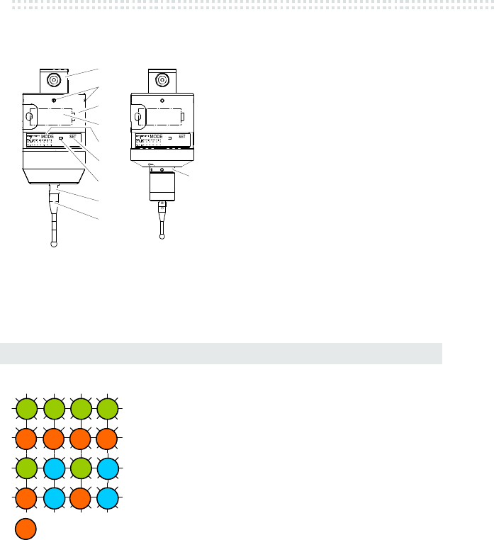
2.1 Description
Fig. 2.1
(1) Shaft for tool holder BTH
(2) Centering screws
(3) Battery cover
(4) Battery
(5) Hall sensor MODE
(6) Hall sensor SET
(7) LED Status 3 pcs.
(8) Measuring mechanism
(9) Stylus
(10) Pin hole
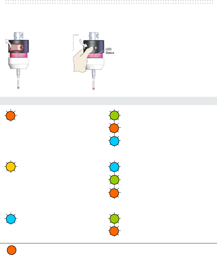
2.2 Display Elements
Colour LED Status (7)
Standby
Stylus initial position
Stylus deflected
Stylus initial position - battery low
Stylus deflected - battery low
Battery low
Fig. 2.2
1
2
3
4
5
6
8
7
9
10
GN
GN
GN
GN
GN
BU
GN
BU
RD
RD
RD
RD
RD
BU
BU
RD
RD
System Overview
6
by Blum-Novotest 2010
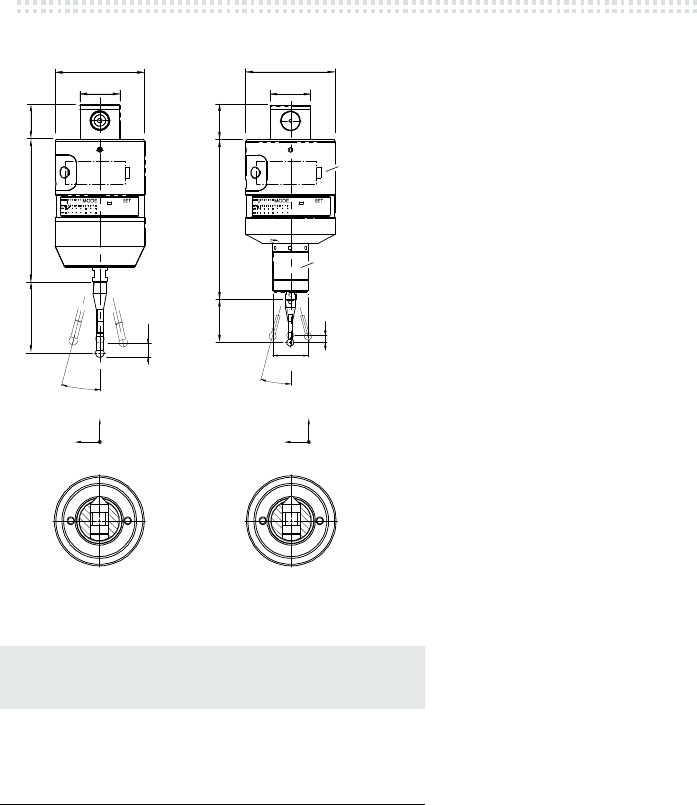
Fig. 2.3
Stylus length
(mm)
Max. deflection X/Y (mm)
TC60 TC63-30/ TC76
30 14 12
50 19 17
75 26 24
100 32 30
150 44
200 57
Tab. 2.1
Ø28
Ø63
TC60
TC63-30
Z
X/Y
Z
X/Y
10
100
L
15°
24
L
Ø28
Ø63
24113
Ø25
TC76-T
TC63-30
L
5
15°
System Overview
by Blum-Novotest 2010
7
2.3 Tool Holder
Type L Order number
System BTH 50(TC60/63-30)
HSK-A 40 57 P03.8000-035.140A
HSK-A 50 63 P03.8000-035.150A
HSK-A 63 50 P03.8000-035.163A
HSK-A 80 55 P03.8000-035.180A
HSK-A 100 60 P03.8000-035.100A
HSK-E 40 57 P03.8000-035.140E
HSK-E 50 63 P03.8000-035.150E
HSK-E 63 50 P03.8000-035.163E
SK 30 60 P03.8000-035.230
SK 40 50 P03.8000-035.240
SK 50 24 P03.8000-035.250
MAS-BT 30 50 P03.8000-035.330
MAS-BT 40 50 P03.8000-035.340
MAS-BT 50 40 P03.8000-035.350
Tab. 2.2
CAUTION
Coolant
Pls. use coolant pipe for tool holder HSK for machining centers
with internal coolant supply.
Type System BTH 50
HSK 25 P03.8000-035.125K
HSK 32 P03.8000-035.132K
HSK 40 P03.8000-035.140K
HSK 50 P03.8000-035.150K
HSK 63 P03.8000-035.163K
HSK 80 P03.8000-035.180K
HSK 100 P03.8000-035.100K
Tab. 2.3
L

System Overview
8
by Blum-Novotest 2010
2.4 Technical Data
TC60 TC63-30 / TC76-T
Approach direction ± X, ±Y, -Z ± X, ±Y, ±Z
a
Measuring force XY-direction 2 N** 1,3 N***
Measuring force Z-direction 7 N 5,9 N
Max. deflection XY ± 15° ± 15°
Max. deflection Z 10 mm 5 mm
Trigger point XY ---- ----
Trigger point Z ---- ----
Max. acceleration 50 m/s
2
50 m/s
2
****
Repeatability** 1 µm 2σ 1 µm 2σ
Max. probing speed 3 m/min 2 m/min
Weight 970 g 680 g (TC63-30)
Protection class IP 68
Signal transmission Funk
Frequency band 2,4000 – 2,4835 GHz
Transmission power 0 dBm
Operating range 15 m
Battery life Ultralife Lithium 6LR61 (9V)
Tool holder HSK–SK-BT BTH 50
Storage temperature -20 °C ... +70 °C
Operating temperature +5 °C ... +50 °C
** Stylus L=50 mm
*** Stylus L=30 mm
**** with accessories (e.g. extension, angle): max. acceleration 10 m/s
2
a)
see chap.3.5
LF: Low Force
Tab. 2.4
System Overview
by Blum-Novotest 2010
9
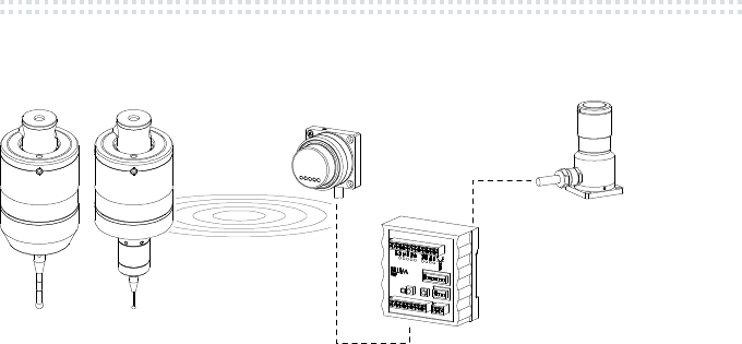
2.5 Complete System
Fig. 2.4
RC66:
⇒ switch ON/OFF via radio signal
⇒ signal transmission for TC series
Installation instructions RC66 (P03.6600-000.011)
Installation instructions IF59-A2 (P03.5900-000.011)
RC66
TC60
IF59 - A2
Z-Nano
Aux
TC63-30
Mounting and Commissioning
10
by Blum-Novotest 2010
3. Mounting and Commissioning
3.1 Batterie einsetzen / wechseln
Empfohlener Batterietyp:
Type Ultralife Lithium U9VL-J
mAh 1200
Contin.
operation
ca. xxx h
5% Use ca. xxx Tage
Standby ca. xxx Tage
Order number 980702003
Dispose batteries acc. to legal requirements.
CAUTION
Risk of short-circuit
Be careful to correct position of gasket.
Keep battery space clean and dry.
1. Clean probe carefully and remove battery cover
2. Exchange battery - take care of polarity!
3. Install battery cover straight (check O-Ring and grease if necessary)
4. Automatic display of the basic adjustments (chap. 3.6)
Fig. 3.1
Mounting and Commissioning
by Blum-Novotest 2010
11
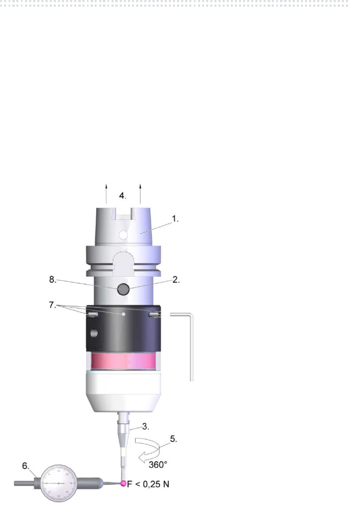
3.2 Mounting of the Tool Holder
1. Insert probe into tool holder (System BTH 50)
2. Tighten screw slightly only
3. Mount stylus (see chap. 3.4)
4. Insert probe into spindle
5. Turn probe by 360°
6. Observe display of run-out – stylus is not allowed to be deflected.
7. Adjust concentricity by crosswise loosening and tightening of the opposite
center screws (4 internal hexagon screws 2 mm) - M
d
< 2 Nm
Run-Out: < 10 µm
8. Tighten holding screw (M
d
= 12 Nm)
9. Carry out calibration cycle
TC60/TC63-30:
2 mm
M
d
< 2 Nm
Fig. 3.2
Mounting and Commissioning
12
by Blum-Novotest 2010
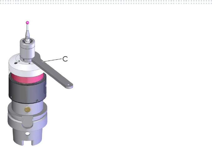
3.3 Mounting of the TC76-T
M
d
= 10 Nm
Fig. 3.3
(C) hook wrench (scope of delivery)
Mounting of the extension / angle: see referring data sheet
Mounting and Commissioning
by Blum-Novotest 2010
13
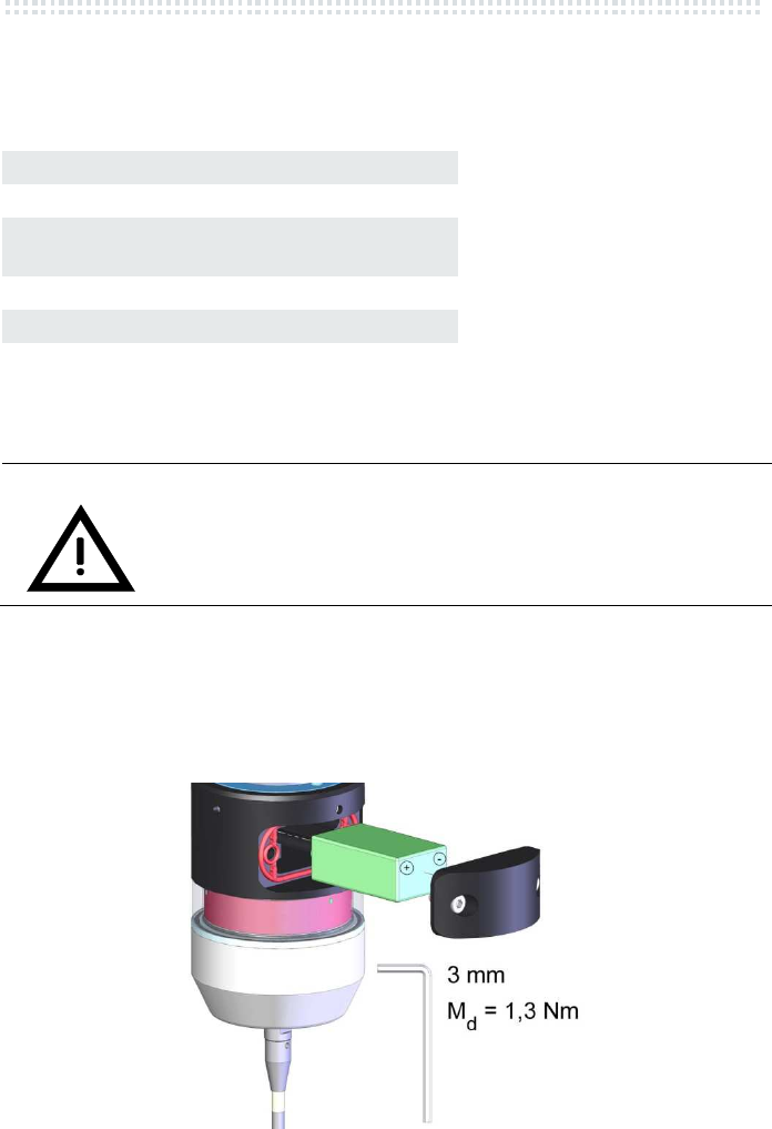
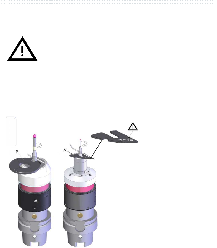
3.4 Mounting of the Stylus
CAUTION
Damage of the measuring mechanism
• TC60: When mounting the stylus into the probe, it is
absolutely necessary to lock the probe with the mounting
tool B to avoid torsion of the measuring mechanism.
• TC63-30 / TC76:
When mounting the stylus into the probe, it is absolutely
necessary to use the interlocking disk (A) (backlash-free).
Pls. take care of the orientation of the interlocking disk (A)
(top side = top)
• Calibrate probe after mounting of stylus!
• Damaged styli are not reusable!
TC60 TC63-30
Fig. 3.4
(A) interlocking disk (scope of delivery)
(B) mounting tool (scope of delivery)
1,5 mm
M
d
= 1 Nm
Mounting and Commissioning
14
by Blum-Novotest 2010
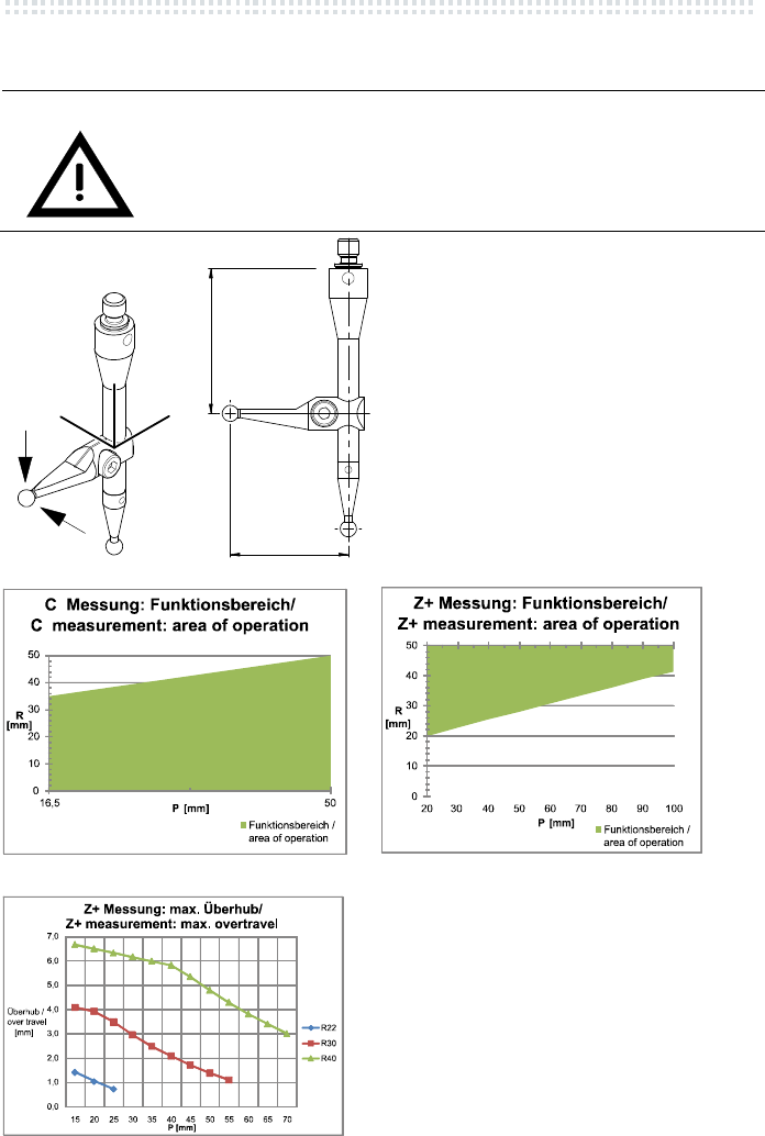
3.5 Cranked Styli (TC63-30/TC76)
CAUTION
Damage of the measuring mechanism
Pay attention to area of operation and max. overtravel
Fig. 3.5
Fig. 3.6 Fig. 3.7
Fig. 3.8
XY
Z
Z+
C
R
P
Mounting and Commissioning
by Blum-Novotest 2010
15
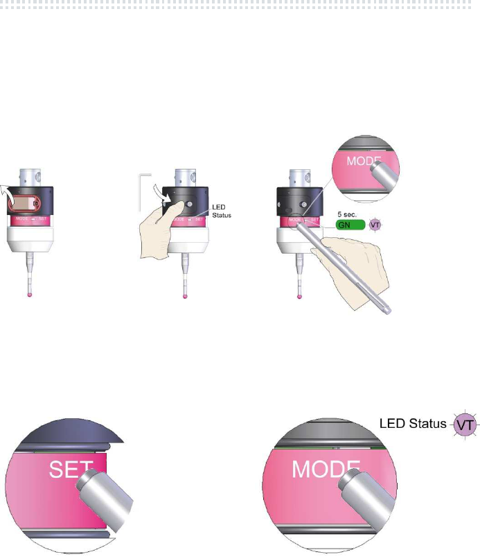
3.6 Display Basic Adjustments
1. Remove battery 2. Insert battery
MODE SET
Transmission mode
Normal*
(3x MODE – SET)
Robust
Fast
Switch-on time
Fast
(3x MODE – SET)
Normal*
Slow
Battery capacity
O.K.
(3x MODE – SET)
low
Battery low
* Standard
RD
GN
BU
RD
GN
BU
OG
BU
RD
GN
RD
Wait 30
sec.
3. Automatic display of the
basic
adjustments:
First colour: MODE
Second colour: SET
RD
Mounting and Commissioning
16
by Blum-Novotest 2010
3.7 Programming of the Basic Adjustments
In this mode the basic adjustments can be set.
1. Remove Battery 2. Insert Battery 3. Activate programming mode
(Polarity!) during display phase
(MODE):
4. Change adjustments (SET) 5. Menu change (MODE)
hold magnetic pin hold magnetic pin
on inscription SET on inscription MODE
wait 30
sec.
Mounting and Commissioning
by Blum-Novotest 2010
17
Activate programming sequence:
MODE SET
Transmission
Mode
Normal
• standard adjustment
Robust
• ambient conditions with
radio interferences
• high chip pollution
Fast
• fast measuring speeds
• interference-free ambient
conditions
Switch-on
time
Fast
• fast switch-on time
• setting decreases battery life
Normal
• normal switch-on time
• standard setting
Slow
• low switch-on time
• setting increases battery life
• not suitable for switch on/of
impulse controlled
Automatic display of the basic adjustments
Standby
RD
GN
BU
OG
BU
RD
GN
RD
Maintenance
18
by Blum-Novotest 2010
3.8 Probe Pairing
Installation instructions IF59-A2 (P03.5900-000.011)
3.9 Switch-on Probe (via radio receiver)
Optical by e.g. M-Code
Installation instructions RC66 (P03.6600-000.011)
Installation instructions IF59-A2 (P03.5900-000.011)
4. Maintenance
• The probe needs minimum
maintenance only
• Keep the glass ring clean
• Check bellows for damages
4.1 Cleaning of the transparent ring
Please do always use mild detergents (e.g. neutral soap
solution or diluted washing-up liquid) for cleaning of the
transparent ring. Please do always use a soft, clean cloth to
clean.
CAUTION
Damage of the transparent ring
Please, do not use any detergents containing acetone,
alcohol, cleaning benzine or solvent! They can damage the
transparent ring.
Please, do not use any detergents containing abrasive
substances (e.g. scouring powder or cleansing milk. They can
damage the transparent ring!

Maintenance
by Blum-Novotest 2010
19
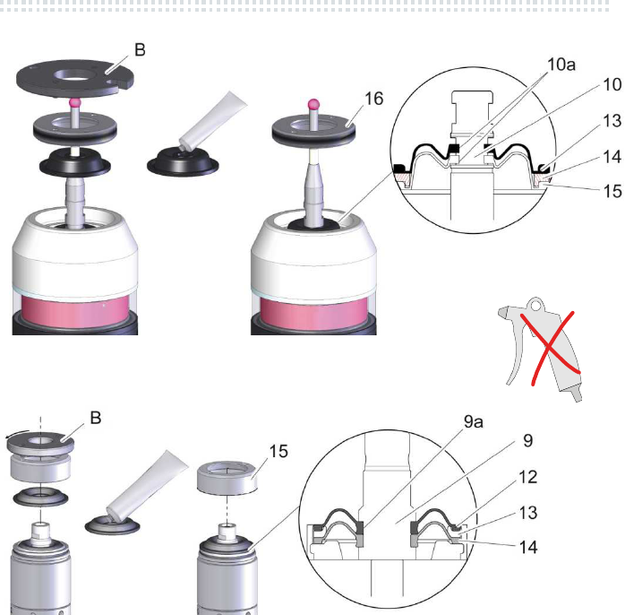
4.2 Exchange of External Bellows
CAUTION
It is not allowed to exchange the internal bellows!
In case that it should be damaged, please send probe for
repair.
Damage of the measuring system
The measuring system is not allowed to be twisted!
TC76-LF (low force):
The bellows is allowed to be exchanged by Blum-Novotest
only!
1. Clean probe and remove stylus if necessary (chap.3.4), while using the
interlocking disk (A) resp. mounting tool (B).
2. Remove front ring (16) with mounting tool (B).
3. Remove external bellows carefully (13), without twisting the measuring
mechanism (10).
4. Grease new bellows (13) at the contact surface to the groove slightly
(grease: ISOFLEX TOPAS NB 52 or STABURAGS NBU30).
5. Install new bellows (13), without twisting the measuring mechanism.
The bellows must click to the groove on the measuring system.
Please take care of plane supporting surface of the bellows.
6. Install front ring (mounting tool (B)).
7. Mount stylus while using the interlocking disk (A) resp. mounting tool (B).
8. Carry out calibration cycle.
Maintenance
20
by Blum-Novotest 2010
Fig. 4.1 TC60
Fig. 4.2 TC63-30 / TC76
(10) Measuring mechanism (14) Centering ring
(10a
)
Groove (15) Internal bellows
(13) External bellows (16) Front ring
Trouble Shooting
by Blum-Novotest 2010
21
5. Trouble Shooting
Error Possible cause Countermeasures
LED Status flashes
resp. LED light
unsteady
Battery is low Check batteries and exchange them if
possible
LED Status shines red Battery is weak Exchange batteries
LED Status changes
from green to violet
while inserting the
batteries without
deflecting the stylus
resp.
LED Status flashes red
Control sends signal
„deflected“ without
deflecting the stylus
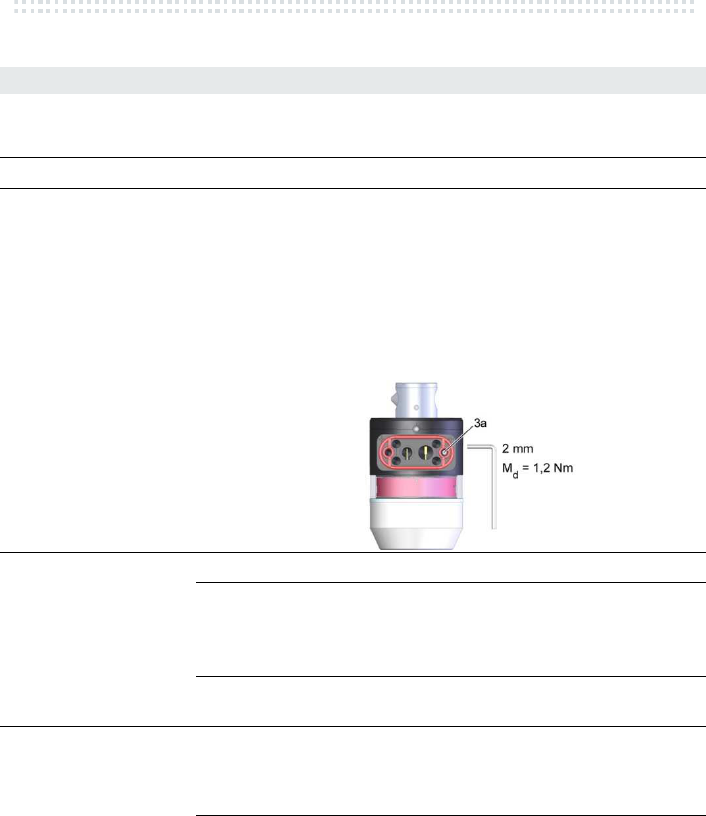
No pressure
com-pensation
after transport by
airfreight
Provide pressure compensation:
1. Remove cover from battery box
2. Loosen thread pin (3a), approx. 2
revolutions
3. Deflect stylus shortly in Z-direction,
wait for approx. 1 minute
4. Then tighten thread pin again
5. Fit battery box cover precisely and
mount it
No activation of the
probe is possible
Battery is empty Insert new batteries
Probe is outside
of the
transmission
range
Check transmission range between RC66
and TC60
Check adjustment of transmission power
(TC60 and IF59-A2)
No pairing of the
probe on IF59-A2
Check pairing
LED Status flashes
white
Probe is outside
of the
transmission
range
Check transmission range between
receiver and probe
Radio error
signals in
transmission
range
Find and clear radio error signals
Order Numbers
22
by Blum-Novotest 2010
6. Order Numbers
Werkzeugaufnahme
BTH 50
See chap. 2
Probe TC60
Basic system TC63-30
P03.6000-010-A1
P06.6300-030-A1
Spare and wear parts
Spare and wear parts are not subject to warranty.
Bellows for TC60 P03.8000-020.002
Bellows for TC76 P03.8000-020.010
Battery for Probe TC60 / 63-30
Type Ultralife Lithium U9VL-J-9V
1200mAh
980702003
Accessory set for TC60 P03.8000-020.001
Accessory set for TC63-30 P03.8000-020.013
Accessory set for TC76 P03.8000-020.012
9V
9V
Order Numbers
by Blum-Novotest 2010
23
Styli for probe TC60
Ceramic
Length Ø
50 mm
2 mm
4 mm
5 mm
6 mm
P03.8000-010.050.02
P03.8000-010.050.04
P03.8000-010.050.05
P03.8000-010.050.06
75 mm 6 mm P03.8000-010.075.06
100mm
2 mm
3 mm
4 mm
5 mm
6 mm
P03.8000-010.100.02
P03.8000-010.100.03
P03.8000-010.100.04
P03.8000-010.100.05
P03.8000-010.100.06
150 mm
4 mm
6 mm
P03.8000-010.150.04
P03.8000-010.150.06
200 mm 6 mm P03.8000-010.200.06
250 mm 6 mm P03.8000-010.250.06
300 mm 6 mm P03.8000-010.300.06
Carbide
Length Ø
50 mm
3 mm
4 mm
5 mm
6 mm
P03.8000-012.050.03
P03.8000-012.050.04
P03.8000-012.050.05
P03.8000-012.050.06
100 mm 4 mm
5 mm
6 mm
P03.8000-012.100.04
P03.8000-012.100.05
P03.8000-012.100.06
Order Numbers
24
by Blum-Novotest 2010
Styli for probe TC76
Ceramic
Length Ø
50mm
2 mm
4 mm
5 mm
P03.8000-020.050.02
P03.8000-020.050.04
P03.8000-020.050.05
75 mm 5 mm P03.8000-020.075.05
100 mm 5 mm P03.8000-020.100.05
Carbide
Length Ø
30 mm
2 mm
3 mm
4 mm
5 mm
P03.8000-022.030.02
P03.8000-022.030.03
P03.8000-022.030.04
P03.8000-022.030.05
50mm
3 mm
4 mm
5 mm
6 mm
P03.8000-022.050.03
P03.8000-022.050.04
P03.8000-022.050.05
P03.8000-022.050.06
75 mm 5 mm P03.8000-022.075.05
100 mm 5 mm P03.8000-022.100.05
Styli for probe TC76
Adapter
P03.8000-025.300
Länge □
Stylus 27 mm
30 mm
36 mm
47 mm
52 mm
62 mm
77 mm
Q6
Q6
Q6
Q6
Q6
Q6
Q6
P03.8000-025.342
P03.8000-025.341
P03.8000-025.343
P03.8000-025.340
P03.8000-025.345
P03.8000-025.344
P03.8000-025.346
Adapter
Tasteinsatz / stylus

Shipping Instructions / Storage
by Blum-Novotest 2010
25
7. Shipping Instructions / Storage
• If the probe should be stored for a longer period, please
remove the battery from the battery box.
• If you return the probe for repair, please enclose a detailed
error description and the probe certificate.
• The probe is to be returned in the original packing only.
• The packing is not allowed to deflect the probe, neither in
X/Y- nor in Z-direction.
• Tool holder and battery are to be removed before packing.
• The probe should be packed shock and pollution
protected.

Radio Approval
26
by Blum-Novotest 2010
8. Radio Approval
Area: Radio Approval: Regulations:
Europe: 0681 EN 300 328 V1.4.1,
EN 301 489-17 V1.2.1,
EN 60950-1:2001
Japan: R 202WW10568411
“This device has been granted a designation number by Ministry of
Internal Affairs and Communications under „Ordinance concerning
Technical Regulations Conformity Certification etc. of Specified Radio
Equipment (特定無線設備の技術基準適合証明等に関する規則)“ Article
2-1-19.
USA: FCC ID: ZCQRCA FCC Part 15
This device complies with part 15 of the FCC Rules. Operation is
subject to the following two conditions: (1) This device may not cause
harmful interference, and (2) this device must accept any interference
received, including interference that may cause undesired operation.
The antenna(s) used for this transmitter must not be co-located or
operating in conjunction with any other antenna or transmitter.
Canada: IC:9570A-RCA
Operation is subject to the following two conditions: (1) this device may
not cause interference, and (2) this device
must accept any interference, including interference that may cause
undesired operation of the device.
This device and its antenna(s) must not be co-located or operating in
conjunction with any other antenna or transmitter.
This equipment complies with IC Canada RF radiation exposure limits
set forth for an uncontrolled environment as per RSS-102 Issue 4.

by Blum-Novotest 2010
27
EC Declaration of Incorporation
acc. to the EC Machine Regulations 2006/42/EC in the edition from 17 May.2006
We hereby confirm that the subsequently following components are defined for the
installation into other machines and that they are in accordance with the following
safety requirements of the EC regulations.
Commissioning is not allowed until it is ascertained that the machines, in which the
components are installed, are in accordance with the EC regulations 2006/42/EC.
The relevant technical information is compiled acc. to annex VII part B and, where
appropriate, we will send the information concerning the components to the different
countries. The industrial property rights of Blum-Novotest GmbH will remain unaffected.
Component name: P03.6000 / P06.3300
Probe for workpiece measurement
Safety requirements
2006/42/EG, Annex I 1.5.1
Applied standards:
EC-Regulations: 2004/108/EG
2006/95/EG
1999/5/EG
Applied harmonized standards: EN61000-6
EN60204-1
EN ISO 12100
EN 300 328
EN 301 489-17
EN 60950-1:2001
Applied national standards: DIN VDE 0100
DIN VDE 0113
Authorised presentative for technical information: Blum-Novotest GmbH
Kaufstr. 14
88287 Gruenkraut, Germany

28
by Blum-Novotest 2010
Service Order
Please fill out completely this repair order and attach it to the system. This will
save you and us costs due to time-consuming inquiries and ensures a quick
repair.
Blum-Novotest GmbH
Kaufstr. 14, 88287 Gruenkraut/Gullen - Germany
Tel. +49 751 6008-0, Fax. +49 751 6008-156
Company:
Department:
Contact:
Address:
Phone:
Fax:
Email:
Probe Type, Serial No.:
Machine Type,
Manufacturer:
Description of Defect:

focus on productivity
focus on productivity
Blum-Novotest GmbH
Kaufstr. 14
88287 Gruenkraut, Germany
Tel.:+49 751 6008-0
Fax:+49 751 6008-156
www.blum-novotest.com
vk@blum-novotest.com
Hotline:
Vertrieb/sales: Tel.:+49 751 6008-200
Service LaserControl : Tel.:+49 751 6008-202
Service Messtaster/probes: Tel.:+49 751 6008-203
Blum-Novotest GmbH Prüftechnik KK Blum Laser Measuring Technology
Willich, Germany Nagoya, Japan
Tel. +49 2154 921970 Tel. +81 568 74-5311
Blum-Novotest Srl Blum-Novotest
Como, Italy Shanghai, China
Tel. +39 031 283 955 Tel. +86 21 52080480
Blum-Novotest Ltd. Blum Production Metrology Co., Ltd.
Birmingham, England Taichung, Taiwan
Tel. +44 1543 257111 Tel. +886 4 2358 3900
Blum Laser Measuring Technology Inc. Blum Production Metrology Pte. Ltd.
Cincinnati, USA Singapore, Singapore
Tel. +1 859 3446789 Tel. +65 62720998
Blum-Novotest Sarl Blum-Novotest Ltd.
Bordeaux, France Soul, Republic of Korea
Tel. +33 55702 0135 Tel. +82 2 2026-1300
Blum-Novotest s.r.o.
Kroměříž, Czech Republic
Tel. +420 573 330373
Support