Bob Long Gen1 Users Manual Intimidator Instruction
Bob-Long-Classic-Users-Manual-804404 bob-long-classic-users-manual-804404
2015-09-01
: Bob-Long Bob-Long-Gen1-Users-Manual-804410 bob-long-gen1-users-manual-804410 bob-long pdf
Open the PDF directly: View PDF ![]() .
.
Page Count: 28
May 2001

Table of Contents
Title Page
Safety.............................................................................................................................. 1
Warranty ......................................................................................................................... 2
Theory of Operation........................................................................................................ 2
General Description ........................................................................................................ 2
Specifications.................................................................................................................. 3
Components.................................................................................................................... 4
Operation........................................................................................................................ 7
Gas Configurations ......................................................................................................... 7
Ammunition Aspects ....................................................................................................... 8
Regulators ...................................................................................................................... 8
Electronics .................................................................................................................... 10
Disassembly/Assembly ................................................................................................. 14
Maintenance ................................................................................................................. 20
Troubleshooting ............................................................................................................ 21

Intimidator-1
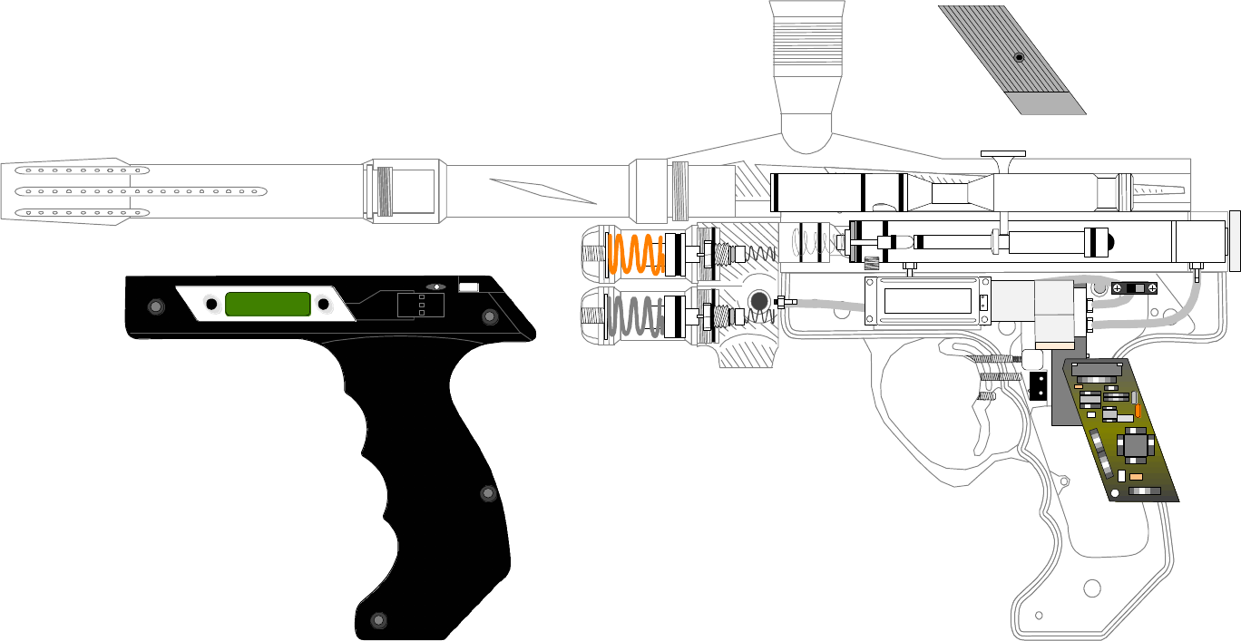
Congratulations on your purchase of the Intimidator paintball marker. The Intimidator
represents the latest in paintball marker technology at a very affordable price. Before
operating your Intimidator, please read the entire manual carefully.
WARNING
This paintball marker is not a toy. Misuse or mishandling can
result in serious injury or death. Every person within range of a
loaded paintball gun must wear eye protection specifically
designed for paintball. Recommended at least 18 years of age
to purchase, 14 years old to use with adult supervision or 10
years old to use on paintball fields meeting ASTM standards
F1777-97. Ensure you read entire instruction manual before
operating your Intimidator.
SAFETY
Please follow all local, state, and federal laws concerning the operation and use of
paintball markers.
By purchasing this paintball marker you assume all liability.
B.L.A.S.T. assumes no liability for injury or death due to misuse or mishandling of this
marker.
q Never point a paintball marker at anyone not wearing paintball-approved goggles.
Even at the lowest possible operating velocity, a paintball will cause serious injury
should it hit someone in the eye area.
q Never look down the barrel of your marker with or without wearing paintball
approved goggles.
q Before performing any maintenance on the marker, ensure air source is
disconnected and marker has been dry fired.
q Leave the ON/OFF switch in the OFF position whenever marker is not operational.
q Always insert barrel plug in barrel when marker is not operational. Remove only in
designated operational areas.
q Only play at commercial playing fields that have a chronograph, referees, and clearly
marked safe areas. Chronograph your marker before each game to ensure marker
is operating at a safe velocity. Safe velocity is considered to be 280 feet per second
(fps).

Intimidator-2
WARNING
Make sure marker is not shooting at a dangerous velocity.
Ensure all participants are wearing the proper paintball safety
equipment. You will be held liable if someone is hurt by a
paintball fired from your marker regardless of fault.
WARRANTY
B.L.A.S.T. warrantees the Intimidator against damages in manufacturing and defects.
Electrical components are warranted for a period of 90 days. Wire harnesses located
within the grip frame will only be warranted against manufacturing defects.
For questions concerning your Intimidator manual please call (925) 625-7929.
THEORY OF OPERATION
The Intimidator marker is a solenoid controlled open-bolt design, very similar to the
popular open-bolt blowback design found in the Spyder. The primary difference is that
instead of a blowback re-cocking on a spring-loaded striker, the bolt is locked into a dual
pressurized machined slider. The back of the chamber is pressurized to move the bolt
forward, and the front is pressurized to move the bolt backward. This allows for very
low cycling pressure, as well as much less cocking recoil. An electronic 4-way valve
controls this slider.
GENERAL DESCRIPTION
The marker includes dual regulators. Both regulators are mounted on the front of the
Intimidator, with standard 3/8-in. hex key velocity adjustments. The high-pressure
regulator is mounted at the top of the regulator base and maintains the firing rate of the
Intimidator. The low-pressure regulator, which is mounted directly below high-pressure
regulator, maintains the cycling rate. All functions are electronically controlled via a
circuit board and 4-way air valve. Settings are changed via a 2-button, internally lit
Liquid Crystal Display (LCD) screen. Rates of fire are variable from 8.1 to 14 balls per

Intimidator-3
second (bps), firing modes are from semi auto, full auto, 3 shot burst, 6 shot burst,
turbo, and reactive. Located within the marker body is a pair of infrared anti chop eyes.
The anti chop eye consists of a set of sensors mounted in the bottom of the breach to
restrict firing until the ball has completely loaded in the breach. The trigger is fully
adjustable, with adjustments for spring tension, pull restriction and firing pull. The gun
will perform on CO2 or HPA/Nitro (factory recommended). The regulator base houses a
standard ASA-threaded hole, for an external regulator or a gas-through grip. The marker
includes a built in drop forward to help balance the marker. The Intimidator comes
stock with a 10, 12, or 14 inch two piece Bob Long barrel.
SPECIFICATIONS
Model ................................................................................................................Intimidator
Caliber.......................................................................................................................... .68
Action ...................................................................................................Electro-Pneumatic
Power (air).......................................... CO2 or Compressed Air/Nitrogen (recommended)
Power (electronics) ......................................................................................9-Volt Battery
Cycle Rate..........................................................................up to 14 paintballs per second
Effective Range.................................................................................................. 150+ feet
Weight.............................................................................................. 2 pounds, 10 ounces
Length .......................................................................................... (14” barrel) 22.5 inches
(10” barrel) 19 inches
Height..............................................................................................................10.5 inches
Intimidator-4
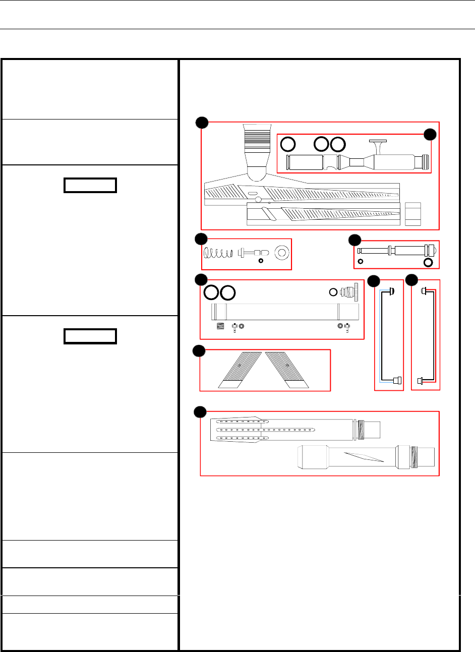
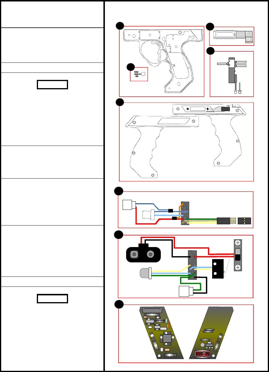
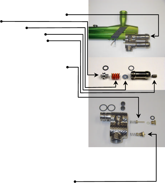
COMPONENTS
1. Body Assembly
• Feed Tube (attached w/black max)
• Body
• Decoration Block
2. Bolt Assembly
• Bolt
• 3 x 015 O-Rings
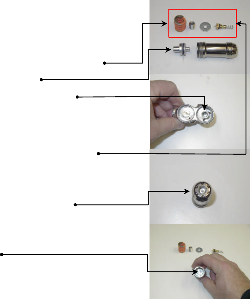
WARNING
Grease Poppet Assembly every 2000 to
3000 rounds fired. Doing this will reduce
cup seal wear. DO NOT use lightweight oil
as lubricant.
3. Poppet Assembly
• Cone Shaped Spring
• Poppet
• 1 x 004 O-Ring
• Cup Seal
WARNING
Grease Ram Assembly every 2000 to 3000
rounds fired. Doing this will reduce O-ring
wear. DO NOT use lightweight oil as
lubricant.
4. Ram Assembly
• 1 x 006 O-Ring
• 1 x 011 O-Ring
• Ram
5. Ram Sleeve
• 2 x 015 O-Ring
• 1 x 011 O-Ring
• Sleeve Cap
• 2 x Barbs w/fiber washers
• Retaining Allen
6. Left Eye Sensor Harness w/female
connector
7. Right Eye Sensor Harness w/male
connector
8. Left/Right Eye Covers
9. Barrel Assembly (2 piece Bob
Long)
Body Assembly
4
006 011
3
004
5
015 011
2
1
015
67
8
9
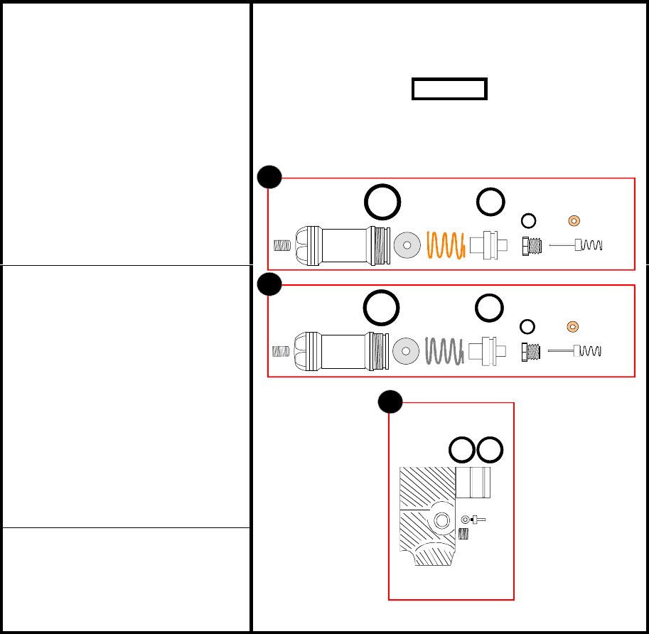
Intimidator-5
1. High Pressure Regulator
• 3/16 Allen (velocity adjustment)
• Regulator Housing
• 1 x 016 O-Ring
• Spring Base (washer)
• Spring (orange)
• 1 x 113 O-Ring
• Piston
• 1 x 010 O-Ring
• Pin Valve Base (brass)
• 1 x 006 Teflon O-Ring
• Pin Valve
• Pin Valve Spring
2. Low Pressure Regulator
• 3/16 Allen (velocity adjustment)
• Regulator Housing
• 1 x 016 O-Ring
• Spring Base (washer)
• Spring (Grey)
• 1 x 113 O-Ring
• Piston
• 1 x 010 O-Ring
• Pin Valve Base (brass)
• 1 x 006 Teflon O-Ring
• Pin Valve
• Pin Valve Spring
3. Regulator Base
• 2 x 015 O-Ring
• 1 x Barb w/fiber washer
• Base
• Base Retaining Allen
Regulator Assembly
WARNING
Grease Regulator Piston every 2000 to 3000 rounds
fired. Failure to do this will result in excessive
Regulator Housing wear.
1
006 Teflon010
113
016
006 Teflon010
113
016
2
015
3
Intimidator-6
1. Trigger Frame
• Trigger
• Frame
2. Trigger Adjuster
• 3 x allen screws
• Spring
• Spring Base
3. LCD Screen
WARNING
DO NOT use lightweight oil on marker. Oil
will destroy internals of Air Valve.
4. Air Valve
• Hosheta w/male Connector (2 black
wires)
• Humphreys w/male Connector
(green/black wires)
5. Left/Right Grip
• Left Grip w/LCD Screen Selection
Membrane and female Connector
• Right Grip
6. 12 Point Harness
• Right Eye Sensor w/female
Connector
• Left Eye Sensor w/male Connector
• LCD Screen Selection Membrane
Male Connector
7. 14 Point Harness
• Connection to 9-Volt Battery
• Connection to ON/OFF Switch
• Connection to Indicator Light
• Connection to Trigger Micro-switch
• Air Valve Female Connector
8. Circuit Board
WARNING
Ensure gun air is disconnected and
gun is discharged before making any
mechanical adjustments to marker
internals or electronics.
Trigger Assembly
1
2
4
3
5
6
7
8

Intimidator-7
OPERATION
GAS CONFIGURATIONS
CO2
When operating the Intimidator on CO2 it is strongly recommended to use a form of
the following:
• High Flow Expansion Chamber
• CO2 specific Regulator
• Bottom Line w/tilt
• Anti-Siphon Tank
• Remote with Harness Mounted Tank
Preset HPA/Nitrogen
When utilizing a preset HPA/Nitrogen system it is best to use an external regulator.
This reduces the possibility of over pressurizing the o-rings. Factory recommends
500 psi as output pressure. As most preset systems are around 800 to 850 psi
output pressure, using an external regulator provides the opportunity to reduce output
pressure to the factory recommended 500 psi. The internal high-pressure regulator
continues to remain the dominant high-pressure regulator over the external regulator.
Therefore, velocity adjustments will continue to be made at the internal high-pressure
regulator.
Adjustable HPA/Nitrogen
This is the factory recommended means of airflow for the Intimidator marker.
By setting the output pressure to 500 psi satisfies the air requirement for
the marker and does not allow over pressurizing of the o-rings.

Intimidator-8
AMMUNITION ASPECTS
Hopper
The Intimidator requires a high flow of paintballs to make full use of its features. To
satisfy this the use of the motorized loaders are recommended.
Paint
Using top grade paint ensures the utmost in performance and accuracy.
REGULATORS
Low Pressure Regulator
The low-pressure regulator (lpr) is mounted at the lower attachment point of the
regulator base. Small velocity adjustments are made at the lpr. Velocity adjustment
is achieved with a standard 3/8in hex key. Operating pressure for the lpr is between
50 and 100 psi. Operationally speaking, the lower the better, as when the pressure
gets too high, the chances of internal air leaks increases, the recoil gets stronger.
When the pressure is too high a noticeable ping sound can be heard during
operation. When the pressure is tool low the marker will be restricted in firing. There
is an option for gauge attachment left side of the regulator base. It is not 100%
necessary; therefore the Intimidator does not come from the factory with one
attached. Although, during regulator setup, when the internal pressure is changed it
is very useful. Any standard 1/8in npt gauge is sufficient.
High Pressure Regulator
The high-pressure regulator (hpr) is mounted at the upper attachment point of the
regulator base. Large velocity adjustments are made at the hpr. Velocity adjustment
is achieved the same as the lpr. The only difference between the lpr and hpr is the
operating pressure range. Pressure will vary between 200 to 300 psi. The primary
use for the hpr is to control ball speed. When adjusting the velocity after adjusting
the regulator pressure, 3 to 4 shots should be fired to allow the regulator to flatten
out. As before, a gauge is not included, or necessary, but recommended.
Intimidator-9
Low Pressure Conversion
To convert the high pressure regulator to low pressure follow the steps below:
1. De-gas marker.
2. Decrease velocity adjustment to relieve spring
pressure.
3. Unscrew the high-pressure regulator housing.
4. Remove piston.
5. Remove orange spring.
6. Remove spring washer.
7. Remove velocity adjuster completely.
8. Turn piston around so that large end is facing
towards pin valve.
9. Install piston, pushing it all the way until it stops.
10. Remove pin valve assembly.
11. Screw regulator housing onto marker.
Note: At this time the low-pressure conversion
is complete. Listed below are key points to
remember.
q Save the removed parts encase you wish to put
the regulator back to original state.
q An external regulator is required when converting
to low pressure.
q Remember to completely remove the velocity
adjuster. Failure to do this will not allow enough
volume for proper recovery.
q Remember to remove pin valve assembly.
Failure to do this will not allow air into required
chambers.
q Ensure large end of piston is facing towards pin
valve.

Intimidator-10
ELECTRONICS
Battery Information
The intimidator uses a standard 9v battery. To change the battery remove the 4
allen screws on the right side grip. The battery fits into the bottom (drop-forward) of
the grip frame. Disconnect the old battery and re-connect the new.
Anti Chop Eye
The Anti-Chop Eye is a pair of photo sensors in the bottom of the breach determining
when the paint ball is seated and ready fire. The EYE mode within the mode menu
can be set to determine how long the marker waits after seeing the ball before it will
fire. Factory recommended setting is 1ms. Refer to Figure 1 for available settings.
Light Emitting Diode (LED)/Liquid Crystal Display (LCD)
When the gun is on, the LED will light with certain codes representing the status of
the marker. The codes are as follows:
q Solid Orange: The marker is in the bootup process.
q Flashing Green: Standard operation
q Solid Green: Marker operational
q Flashing Red: Allows normal operation, indicates battery is low.
q Solid Red: Marker not operational/marker in menu mode.
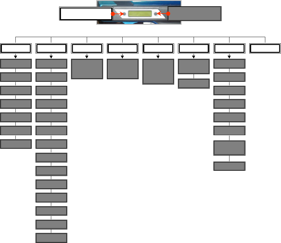
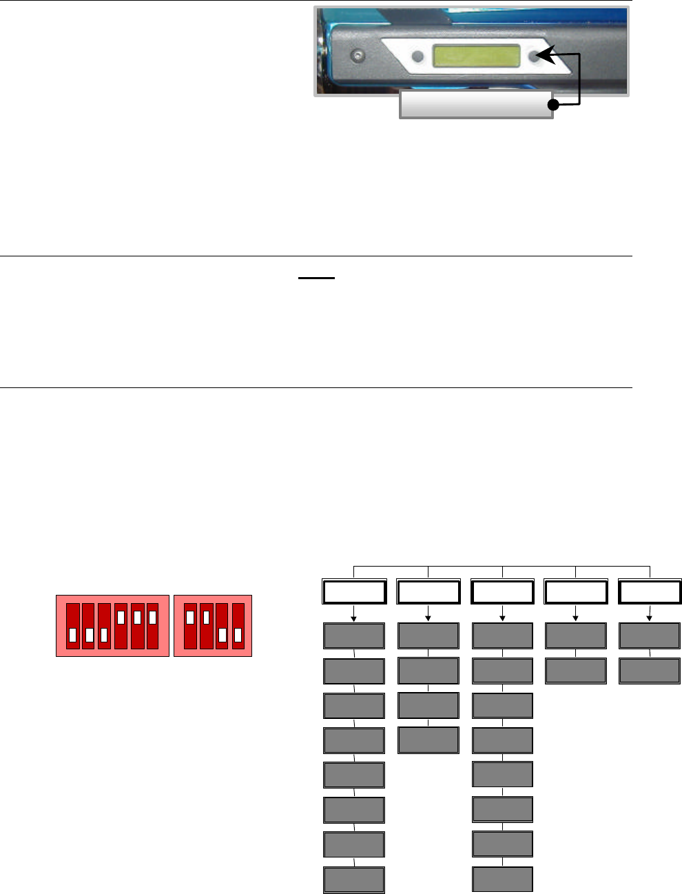
Mode Selection
The LCD is a two-button membrane, backlit, and menu driven system. To bring up
menu options for the gun, hold down both buttons until backlight illuminates (approx.
1 second). Upon release you will placed in the first menu (MODE = Firing Rate). A
definition of firing rates follows:
q Semi Auto: one pull, one shot
q Full Auto: Fires continually until trigger is released (up to 30 shots).
q 3 Shot: Fires 3 shots at the same rate as Full Auto.
q 6 Shot: Fires 6 shots at the same rate as Full Auto
q Turbo: Fires alternating 1 shot/2 shots per trigger pull.
q Reactive: Fires two shots per trigger pull.
Intimidator-11
q Test: Bypasses the Ball Sensor to allow for test firing.
The left button scrolls through the eight available menus. Below are the definitions
for the remaining menus:
q RATE: Determines how fast the marker cycles in balls per second (bps).
q EYE: Determines how long the marker delays (in milli-seconds) after seeing a
ball before firing.
q DWELL: Determines how long the bolt stays forward before repeating cycle.
q TIME: Determines game timer setting. Selectable in hour increments.
q DISP: Determines what is displayed on the LCD.
q EXIT: Saves changes to menu selections and returns marker to ready state.
The right button selects options within the menus. Reference Figure 1 for the
available options:
MODE RATE EYE DWELL TIME CNTR DISP
Semi-Auto
Full-Auto
3 Shot
6 Shot
Turbo
Reactive
Test
8.1
8.4
8.7
9.0
9.3
9.7
10.1
10.5
10.9
11.4
12.0
12.6
13.3
14.0
Selectable
between
1-15
Blank
Time Only
CNTR Only
FM Only
FR Only
FM & FR
Fm & FR &
CNTR
Reset
Count
No Reset
Selectable
between
1-50
Selectable
in hour
increments
from 1-99
Competition
EXIT
Select Mode Selects options
within Mode
Figure 1. Menu Tree
Intimidator-12
The MODE menu will be the most popular menu option used. For this reason the
factory has defaulted it as the first selectable menu when the membrane buttons are
activated. These procedures will provide familiarization on navigation through the
remaining menus. Procedures to change the firing rate of the Intimidator are as
follows:
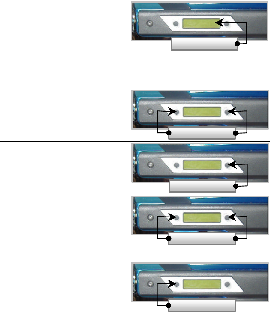
Changing the Firing Mode
1. Place the ON/OFF switch to ON.
2. Observe in the Display Window
Bob Long’s
INTIMIDATOR
INTIMIDATOR
LCD Ver 1.4.3
Turbo 0000
14.0/sec 45:00
3. Press and hold both membrane
buttons down at the same time
until backlight illuminates.
4. Observe in the Display Window
User Setup→→MODE
5. Press right membrane button.
6. Observe in the Display Window
User Setup→→MODE
Semi-Auto
7. Press the left membrane button to
select the desired firing mode.
8. Once the firing mode is selected
press the right membrane button.
9. Observe in the Display Window
User Setup→→MODE
10. Press the left membrane button
seven times and observe in the
display window.
User Setup→→EXIT
Membrane Buttons
Display Window
Right Button
Membrane Buttons
Left Button
Intimidator-13
11. Press the right membrane button to
save the change.
12. Observe in the display window.
3-Burst 0000
14.0/sec 45:00
Note: 3-Burst was used in this
example. Whatever you as the user
select, will appear in the same
position on the display window.
13. Ensure LED located left of the
ON/OFF switch blinking green.
Note
By pressing and holding the right membrane button for approx. 2
seconds before release, will default the firing mode to Full-Auto
regardless of previous mode selected. To return marker to
previous selected mode simply press and hold the right
membrane button for approximately 2 seconds and release.
DIP Switch Settings
DIP Switch settings determine the default settings used by the marker upon power
up. These switches allow the user to customize the markers default settings. To
access the DIP switches, remove the right side grip. DIP switches are located at the
base of the Circuit Board. Reference menu tree below for appropriate settings.
ON
OFF
1 2 3 4 5 6 7 8 9 10
Based on Version 1.4.3
The example above indicates marker
will power up with the following settings:
q Firing Mode: Semi Auto
q Rate of Fire: 14 Shots/sec.
q Forward Dwell: 6 ms
q Ball in place delay: 1 ms
q Tournament Lock: Disengaged
Right Button
1 through 3
Firing Mode 4 and 5
Rate of Fire 6 through 8
Forward Dwell 9
Ball in Place Delay 10
Tournament Lock
off,off
9 Shots/sec.
off,on
10.1 Shots/sec.
on,off
12 Shots/sec.
on,on
14 Shots/sec.
off,off,off
20 ms
off,off,on
18 ms
off,on,off
16 ms
off,on,on
14 ms
on,off,off
12 ms
on,off,on
10 ms
on,on,off
8 ms
on,on,on
6 ms
off,off,off
Semi Auto
off,off,on
3-Burst
off,on,off
6-Burst
off,on,on
Full Auto
on,off,off
Test
on,off,on
Turbo
on,on,off
Reactive
on,on,on
Unused
off
1 ms
on
Bypass Eye
off
Disengaged
on
Engaged
Intimidator-14
DISASSEMBLY/ASSEMBLY
When disassembling the Intimidator always ensure the marker is de-gassed. The
disassembly portion of this manual will be divided into three sections.
q Trigger disassembly
q Regulator disassembly
q Body disassembly
When assembling the marker perform the respective assembly on reverse order as
disassembly.
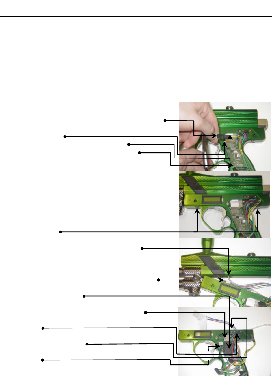
Trigger Disassembly
1. Remove both side grips.
2. Disconnect battery.
3. Disconnect Grip membrane from wire harness.
4. Lift up on LCD white ribbon locks located on
Circuit Board.
5. Remove ribbon from Circuit Board.
6. Remove Circuit Board retaining screw.
7. Disconnect wire harnesses from backside of
Circuit Board.
8. Remove Circuit Board, and place in safe area.
Note: Removing Circuit Board before
disconnecting Trigger Assembly from body will
reduce the risk of damaging the board during
disassembly.
9. Remove Trigger Assembly retaining screws (2
each). Ensure longer screw goes in back when
assembling.
10. Pull Trigger Assembly down to expose airlines.
11. Disconnect airlines from body (3 each).
Note: Use care when removing airlines. Inspect
after removal to ensure no tears took place
during removal.
12. Disconnect Eye Sensor Harnesses (2 each).
13. Disconnect Air Valve from harness (green/black
or black/black wire).
14. Remove Air Valve retaining screw; pull Air Valve
through top of trigger frame for removal.
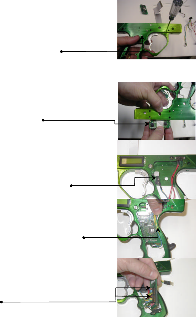
15. Remove ON/OFF switch retaining screws (2
each).
16. Push down on power indicator light; pull from
backside to remove.
17. Remove Trigger Micro-switch retaining screws (2
each).
18. Remove harnesses from trigger frame. Use
caution when pulling eye sensor part of harness
through top of trigger frame.
Intimidator-15
19. Turn trigger frame over and remove LCD screen
retaining screws (4 each). Leave screws in LCD
holes.
20. Remove LCD screen from trigger frame top. Use
caution when removing not to loose screws.
21. Remove trigger spring housing retaining screw (1
each). Use caution as housing and spring will fall
after screw has been removed.
Note: At this time the Trigger is disassembled.
Listed below are key points to remember when
assembly occurs.
q LCD Install: Ribbon comes pre-folded from the
factory. Fold ribbon and place screws in LCD
before placing into trigger frame. Feed LCD
through top of trigger frame. Start all screws in al
holes prior to tightening.
q Trigger Micro-switch: When installing Trigger
Micro-switch, start screws, push solenoid towards
base of trigger frame and tighten screws. This
ensures the Micro-switch flap does not bind
against the trigger spring housing.
q Circuit Board: Do not over tighten the circuit
board. Lay harness in trigger frame to avoid
pinching of wires when attaching grips.
q Harness Connection: When connecting to the
circuit board ensure orange wire is up on 12 point
harness and black and red wire is up on 14 point
harness.
Intimidator-16
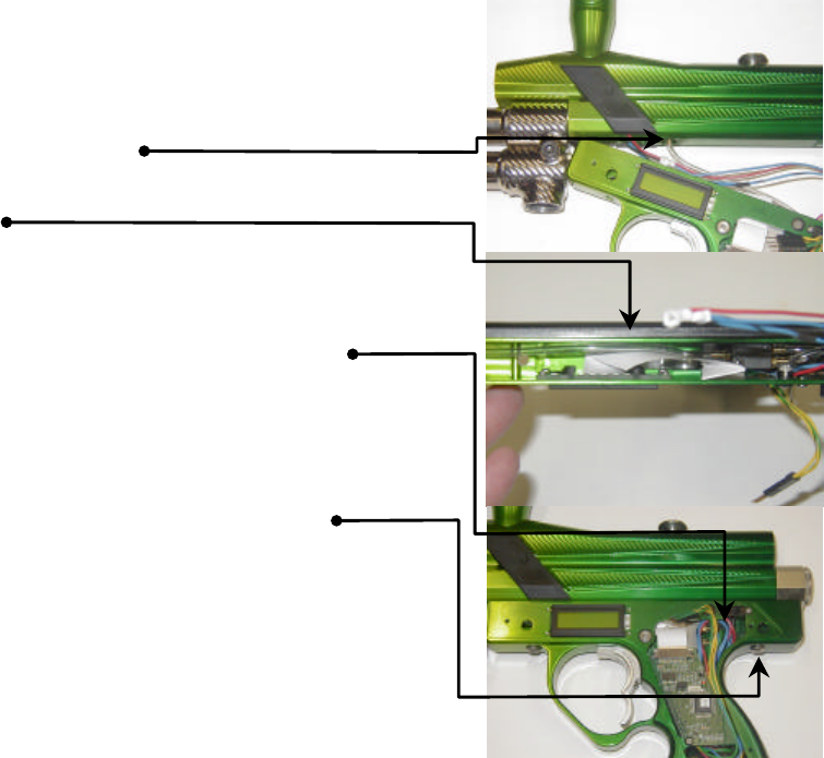
q Air line attachment: Ensure airlines are seated
on air barb bases. This will prevent the
possibility of air leaks.
q Do not pinch airlines when routing through trigger
frame top.
q Eye Sensor connection: After connecting eye
sensor harnesses pull remaining wire through
trigger frame. This avoids pinching of wires
during trigger frame attachment to body.
q Trigger Assembly attachment: When you have
finished assembly of the trigger frame and are
ready to attach to body, ensure longer screw
goes in the rear. Failure to do this will result in
the puncture of the pressurized sleeve.
Intimidator-17
Regulator Disassembly
1. Remove regulator base retaining screw (1 each).
2. Remove poppet spring.
3. Unscrew high-pressure regulator housing.
4. Remove piston.
5. Remove regulator spring.
6. Remove regulator spring washer.
7. Remove velocity adjustment allen.
8. To remove low-pressure regulator repeat steps
3 through 7.
9. Remove high-pressure pin valve assembly.
10. Remove low-pressure pin valve assembly.
11. Remove air barb from backside of regulator
base.
Note: At this time the Regulators are
disassembled. Listed below are key points to
remember when assembly occurs.
q Piston: Ensure cupped small end of piston is
facing towards pin valve (unless high pressure
regulator is converted to low pressure).
q Regulator Spring: Ensure orange spring is in
high-pressure regulator housing and dark gray
spring is in low-pressure regulator housing.
Failure to do this will cause regulators not to
function properly.
q Pin Valve: Ensure pin valve is not bent and seats
in cupped small end of piston. Failure to do this
will cause regulators not to function properly.
q Air Barb: Ensure fiber washer is on air barb base
when installing. This will ensure air barb does
not leak.
q Poppet spring attachment: Ensure small end of
spring sits firmly on poppet.
q Base Attachment: Place small portion of lock
tight on retaining screw when installing. This will
ensure regulator base does not loosen up during
operation.
Intimidator-18
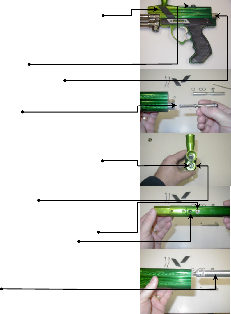
Body Disassembly
1. Remove barrel from marker.
2. Remove Eye Sensor covers (both sides) by
removing retaining screw (1 each side).
3. Remove Eye Sensor Harness (both Sides) by
carefully pulling sensor heads from mounting
holes. Be careful not to loose small o-ring on
each head.
4. Lift up on bolt-retaining pin and slide bolt out of
rear of marker.
5. Remove rear sleeve cap screw.
6. Remove decorative cover.
7. Turn marker up and allow ram to fallout of marker
rear. Hold hand underneath to catch ram. Do
not let ram fall freely on to ground or any other
hard surface.
8. Remove poppet from sleeve front. Use a small
pair of pliers to grab poppet end. Do not use
force on poppet. Poppet will come out with little
or no pulling pressure. Use care not to damage
poppet lip. Damaging poppet lip will not allow the
poppet to seal properly to the cup seal.
9. Remove cup seal. Use extreme caution not to
scratch or damage cup seal. It is recommended
to replace the cup seal every time it is removed.
Any small scratch or fragment on the cup seal will
induce an air leak.
10. Turn body over to gain access to the bottom of
the marker.
11. Remove air barb from middle of sleeve. Do not
loose fiber washer at base of air barb.
12. Remove sleeve retaining allen.
13. At this time you are ready to remove the sleeve
from the body. When removing rotate the sleeve
right and left pulling towards the rear of the
marker. Use caution to avoid cutting the o-rings.
There are sharp openings that the o-rings must
cross.
Note: At this time the Body is disassembled.
Listed below are key points to remember when
assembly occurs.
q O-rings: Apply grease to all o-rings before
installing.
q Front Sleeve O-ring: To ensure a good seal take
a piece of Teflon tape and wrap around groove in
sleeve. Ensure all Teflon tape is in groove.
Place o-ring over the top of the Teflon tape.
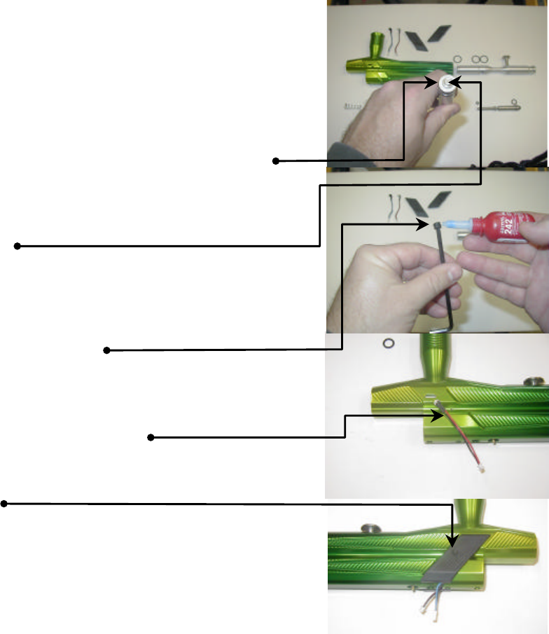
Intimidator-19
q Sleeve Installation: Use caution when installing
the sleeve. Be careful not to cut the o-rings on
the sharp openings.
q Air Barb: Ensure fiber washer is on air barb base
prior to installation. This will ensure proper seal.
q Cup Seal: Ensure cup seal snaps into sleeve
seal. Failure to do this will allow the cup seal to
jump from seat, causing an extreme air leak.
q Poppet installation: Ensure poppet o-ring is well
greased. Allow poppet to slide into sleeve, once
seated tap on poppet end to mate poppet with
cup seal.
q Sleeve retaining allen: Use small amount of lock
tight on allen when installing. Failure to do this
may result in sleeve sliding back, causing
extreme damage to the marker and possible
injury to the operator.
q Eye Sensor Harness: Ensure harness is seated
in grove provided before attaching Eye Covers.
Failure to do this could pinch the wires and
render the eyes inoperable.
q Eye Covers: Do not over tighten the covers.
Over tightening will result in the cracking of the
covers.
Note: The feeder neck is installed with black
max at the factory. To remove the neck, loosen
the allen at the base of the neck, apply heat and
unscrew. Do not attempt to remove the neck
without first removing the retaining allen. Failure
to do this will result in the damage of the neck.
Intimidator-20
MAINTENANCE
WARNING
DO NOT use lightweight oil on marker. Oil will destroy internals
of Air Valve, O-rings, and Cup Seal.
General
Provide all O-rings within the marker a heavy coat of grease. The Poppet and Ram
O-rings need to be greased between 2000-3000 rds. fired. Keep foreign obstructions
out of marker internals.
Regulator
Regulator O-rings should be greased every 5000 rds. fired. Failure to do this will
reduce recover time of Regulators. Additionally, the piston will wear a grove in
Regulator housing. Ensure the Pin Valve lines up with the cup on the Piston. This
will eliminate the inadvertent bending of the pin.
Consumables
Component/Quantity Size
Body Assembly
Bolt (3) .....................................................................................................................015
Poppet (1)................................................................................................................004
Ram Front (1) ..........................................................................................................006
Ram Rear (1)...........................................................................................................011
Pressurized Sleeve (2).............................................................................................015
Sleeve End Cap (1)..................................................................................................011
Cup Seal (1).........................................................................................order from Delta
Regulator Assembly
HPR Housing (1)......................................................................................................016
HPR Piston (1).........................................................................................................113
HPR Pin Valve Base (1)...........................................................................................010
HPR Pin Valve (1).........................................................................................006 Teflon
LPR Housing (1) ......................................................................................................016
LPR Piston (1) .........................................................................................................113
LPR Pin Valve Base (1) ...........................................................................................010
LPR Pin Valve (1) .........................................................................................006 Teflon
Regulator Base (2)...................................................................................................015
Trigger Assembly
Airline (standard Autococker)........................................................ (To regulator) 5.0 in.
(To middle body) 5.0 in.
(To rear body) 2.5 in.
Circuit Board (2).......................................................................................................004

Intimidator-21
TROUBLESHOOTING
Refer to Assembly/Disassembly to perform repairs indicated below.
Problem Cause Repair
When gas is applied to the
gun a load POP is heard
and air is escaping in our
around the Trigger Frame.
Airline or lines have
become stretched or
disconnected from Ram
Sleeve (usually due to over-
pressurizing of the
Regulators).
Re-connect airline.
Replace stretched/leaking
airline.
The Low pressure
Regulator is over-
pressurized and causing
the Air Valve to leak.
Turn down Low Pressure
Regulator.
Foreign Material has lodged
inside Air Valve. It is not recommended to
disassemble the Air Valve.
Remove and return Air
Valve to factory.
Gun leaks from inside the
Trigger Frame and hoses
are fine.
Heavy use of lightweight oil
ion marker causing internal
destruction of Air Valve.
It is not recommended to
disassemble the Air Valve.
Remove and return Air
Valve to factory.
Gun consistently leaks
down the barrel, decreasing
slightly when bolt is pushed
forward.
Heavy use of lightweight oil
causes deterioration of
Poppet O-ring and/or Cup
Seal.
Remove Poppet and
replace O-ring. Remove
and replace Cup Seal.
If bolt moves freely, one or
more of the airlines are
crimped.
Remove grip and re-
position airline/lines
Gun is pressurized and will
not fire.
If bolt does not move,
Trigger Solenoid is sticking
or inoperable. The solenoid
flap wedging against the
Trigger Spring housing
causes this.
Remove Grip and re-
position Trigger Solenoid.
LCD shows nothing or
displays unreadable
characters.
Ribbon has become
disconnected or damaged. Re-connect ribbon to
docking port on circuit
board. If ribbon is
damaged remove and
return to factory.

Intimidator-22
Marker fires with first shot
extremely slow. Poppet O-ring is dry. Grease Poppet O-ring.
High Pressure Regulator is
set to low. Increase pressure in High
Pressure Regulator.
Marker cycles but does not
fire.
Dwell is set to low. Set Dwell, green and black
wire Air Valve requires a
#16 Dwell setting, double
black wire Air Valve
requires #6 Dwell setting.
Regulator Pin Valve has
debris lodged between
valve and seal.
Remove debris from
Regulator Pin Valve.
Regulator/Regulators
pressure will not adjust.
Pin portion is bent causing
unreliable seal. Remove and replace Pin
Valve.
Unexplained ball breakage
and Sensor Eyes are fine. Ball Sizer was not installed
at barrel attachment. Install ball sizer and re-
attach barrel. If your
marker does not have ball
sizers, upgrade the type of
paint your shooting
Gun leaks down barrel. Setscrew used to retain
sleeve has become loose
causing sleeve to move
rearward.
Remove sleeve and replace
front 015 o-ring (placing
teflon tape in groove before
seating o-ring). Re-install
sleeve. Use caution to
ensure you do not cut o-
rings. Use lock-tite on
retaining screw.
Inconsistent velocity. High-pressure regulator
piston dry.
Large ram o-ring (rear) is
worn.
Paint does not fit barrel.
Lube piston
Replace o-ring
Use appropriate size of
paintball

Intimidator-23
When gun is turned to ON,
bolt moves forward and
fires.
Low Battery
Retaining screw for circuit
board is shorting out board.
Remove and replace
battery
Remove retaining screw
and install rubber o-ring
(poppet o-ring works fine).
Re-install circuit board
ensuring screw does not
touch board.
Written By:
Bob Crews
Instructional System Design Specialist
808 Plateau Way Modesto, CA. 95358 e-mail MilitaryPresence@msn.com