Bodycap 043 The Activator is intended to activate the capsule for Telemetry System. User Manual User guide
Bodycap The Activator is intended to activate the capsule for Telemetry System. User guide
UserManual.wiki
>
Bodycap
>
043 User Manual
User_guide.pdf
Navigation menu
Upload a User Manual
Namespaces
Wiki Guide
HTML
PDF
Info
Views
User Manual
Discussion / Help
Navigation
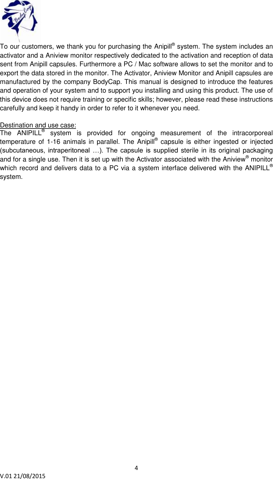
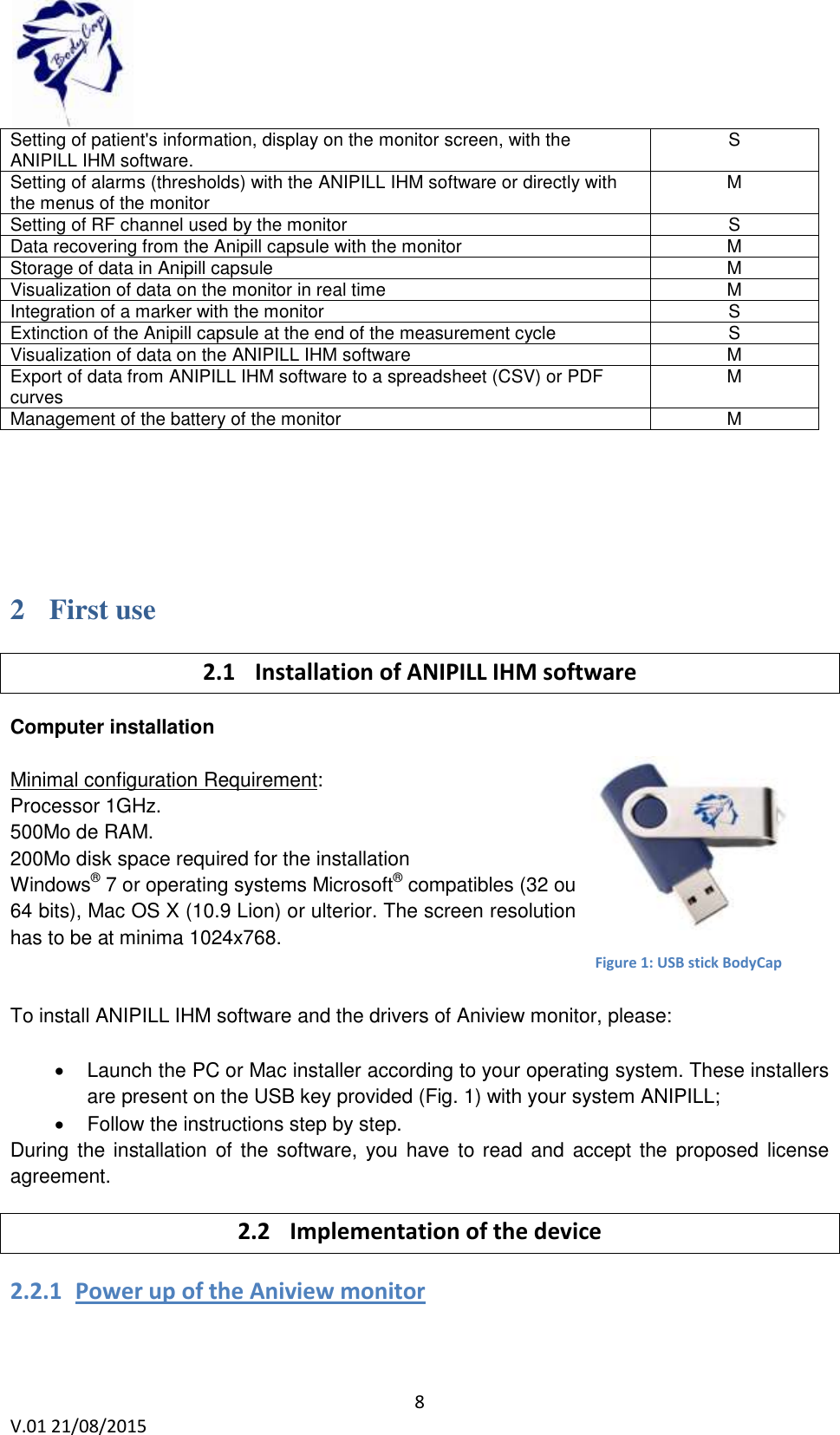
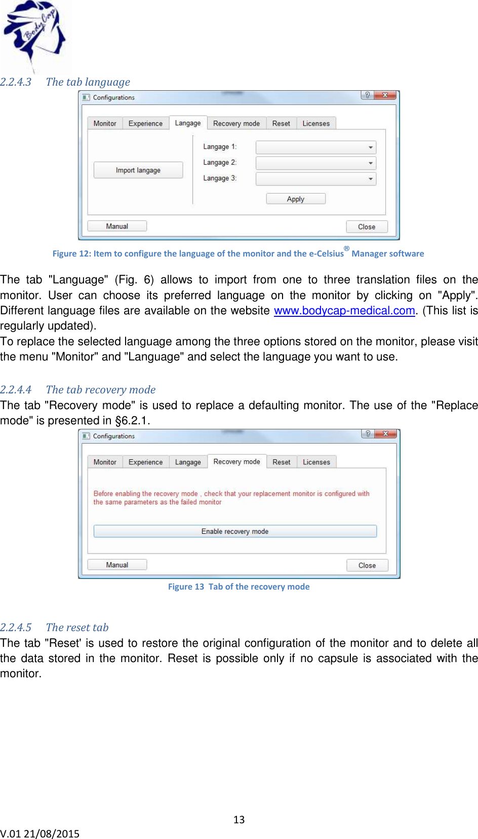
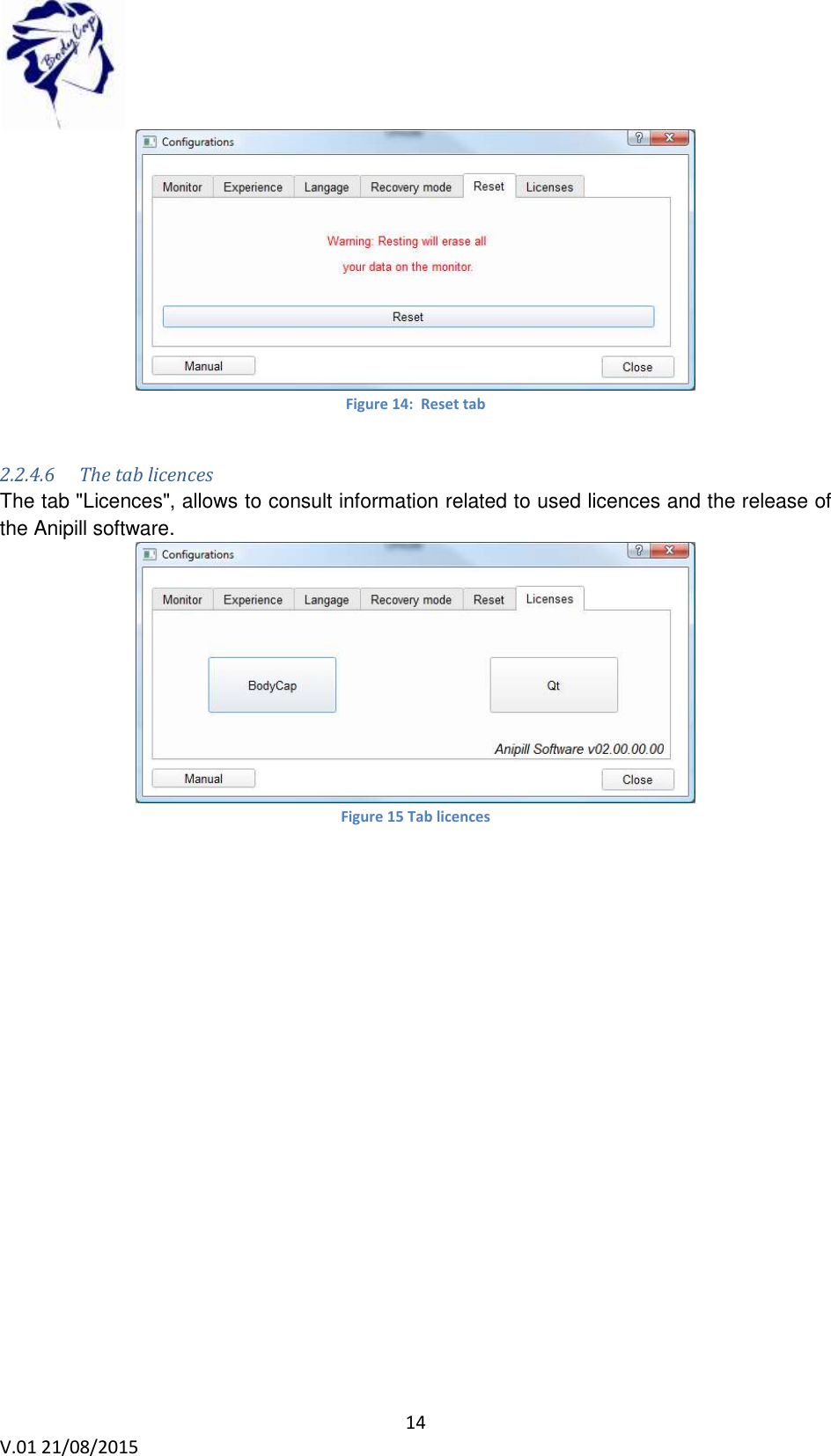
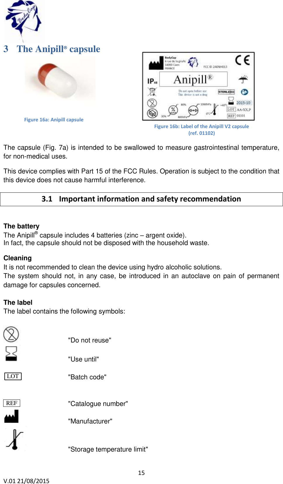
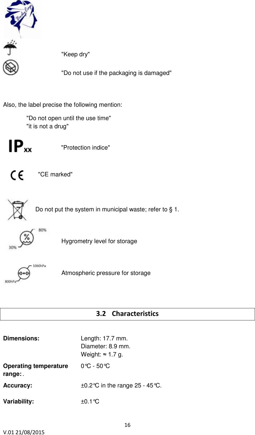
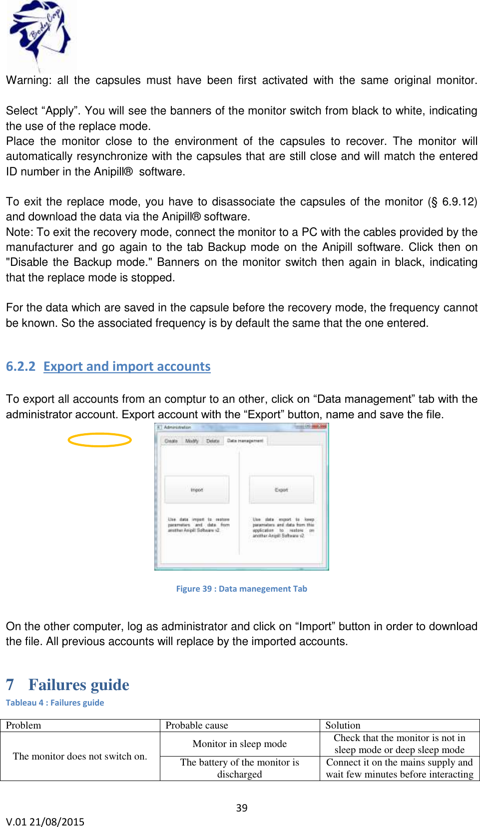
![38 V.01 21/08/2015 6.2 Secondary functions 6.2.1 Recovery mode When the operation of the monitor is disturbed (failure, broken, …), it is possible to recover the communication with capsule which was associated first; via an another monitor. This allow to ensure the continuity of the cycle of measurement It is necessary to start the replace operation with an operational monitor. This mode will allow to retrieve data from all the Anipill capsules communicating on the selected channel, in the communication frequency of the monitor and whose ID number is known. First, it is necessary to bring a functional and charged monitor. Then, check that no capsule is associated with this monitor. Connect it to the Anipill® software and configure the operating channel of the monitor to the same channel as the failed monitor. In fact on the operating channel of the capsules you want to recover [follow the procedure in § 5.8.2]. After you have started the Anipill® software, connect the monitor to a functional PC/Mac with the cables provided by the manufacturer. Select "Recovery mode" on the Anipill® software. Figure 37 Tab "Replace mode" Validate the start of the mode by clicking "Enable recoveryFrecover mode". The following window appears: Figure 38 Id of capsules in recovery mode Enter the ID number of the capsules you want to recover. (§ 6.9.12) The order of capsules does not matter.](https://usermanual.wiki/Bodycap/043/User-Guide-2779286-Page-38.png)