Bodycap 043 The Activator is intended to activate the capsule for Telemetry System. User Manual User guide
Bodycap The Activator is intended to activate the capsule for Telemetry System. User guide
Bodycap >
User_guide.pdf
Version
User manual
AnipillV2
Telemetric system for gastrointestinal temperature monitoring
Before use, please read
carefully theses instructions

2
V.01 21/08/2015
Index
1 Precautions for use ................................................................. 5
1.1 Functions of ANIPILL system ............................................................ 7
2 First use .................................................................................. 8
2.1 Installation of ANIPILL IHM software ............................................... 8
2.2 Implementation of the device ......................................................... 8
2.2.1 Power up of the Aniview monitor ...................................................................8
2.2.2 Supply the batteries .........................................................................................9
2.2.3 Configuration of account in IHM Anipill .........................................................9
2.2.4 Configuration of the monitor......................................................................... 11
3 The Anipill® capsule .............................................................. 15
3.1 Important information and safety recommendation ...................... 15
3.2 Characteristics ................................................................................ 16
4 The Activator ........................................................................ 18
4.1 Important information and safety instructions ............................... 18
4.2 Characteristics ................................................................................ 19
4.3 The buttons .................................................................................... 20
4.4 The LED .......................................................................................... 20
5 Aniview V2 monitor .............................................................. 21
5.1 Important information and safety instructions ............................... 21
5.2 The characteristic ........................................................................... 23
5.3 The buttons .................................................................................... 24
5.4 The LEDs ......................................................................................... 25
5.5 The battery of Aniview monitor ..................................................... 26
5.6 Connection ..................................................................................... 27
5.7 Menus of the Aniview monitor ....................................................... 27
5.8 Main functions ............................................................................... 30
5.8.1 Set the monitor .............................................................................................. 30
5.8.2 Changing the channel used by the monitor ................................................. 30
5.8.3 Activate a capsule .......................................................................................... 30

3
V.01 21/08/2015
5.8.4 Consult temperature data in real time .......................................................... 32
5.8.5 Synchronization of the data in memory of the capsule ............................... 32
5.8.6 Visualization of the end-of-life of the capsule ............................................. 33
5.8.7 Disassociation of a capsule .......................................................................... 33
5.8.8 Use of the monitor screen ............................................................................. 34
5.8.9 Low battery ..................................................................................................... 34
6 Anipill® software ................................................................... 34
6.1 Main fonctions ............................................................................... 34
6.1.1 Unload and consult the temperature data on the Anipill software ............. 35
6.1.2 Visualization of markers from the Aniview monitor .................................... 35
6.1.3 Export temperature’s data unloaded on Anipill software ........................... 36
6.1.4 Consult temperature data in real-time .......................................................... 37
6.2 Secondary functions ....................................................................... 38
6.2.1 Backup mode ................................................................................................. 38
7 Failures guide ....................................................................... 39
8 Cables and power supply ...................................................... 40

4
V.01 21/08/2015
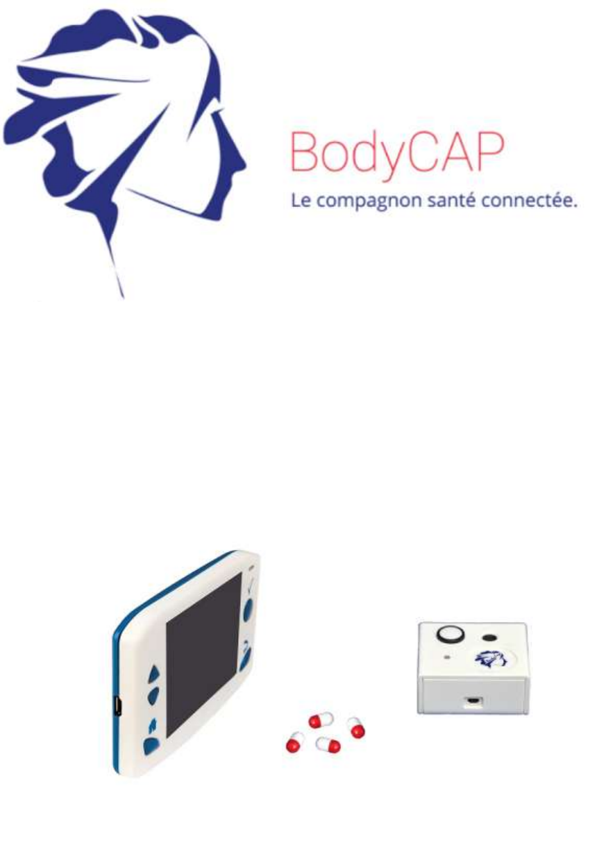
To our customers, we thank you for purchasing the Anipill® system. The system includes an
activator and a Aniview monitor respectively dedicated to the activation and reception of data
sent from Anipill capsules. Furthermore a PC / Mac software allows to set the monitor and to
export the data stored in the monitor. The Activator, Aniview Monitor and Anipill capsules are
manufactured by the company BodyCap. This manual is designed to introduce the features
and operation of your system and to support you installing and using this product. The use of
this device does not require training or specific skills; however, please read these instructions
carefully and keep it handy in order to refer to it whenever you need.
Destination and use case:
The ANIPILL® system is provided for ongoing measurement of the intracorporeal
temperature of 1-16 animals in parallel. The Anipill® capsule is either ingested or injected
(subcutaneous, intraperitoneal …). The capsule is supplied sterile in its original packaging
and for a single use. Then it is set up with the Activator associated with the Aniview® monitor
which record and delivers data to a PC via a system interface delivered with the ANIPILL®
system.

5
V.01 21/08/2015
WARNING TO USERS IN THE UNITED STATES
This equipment has been tested and found to comply with the limits for a Class B digital device,
pursuant to Part 15 of the FCC Rules. These limits are designed to provide reasonable protection
against harmful interference in a residential installation. This equipment generates uses and can
radiate radio frequency energy and, if not installed and used in accordance with the instructions, may
cause harmful interference to radio communications. However, there is no guarantee that interference
will not occur in a particular installation. If this equipment does cause harmful interference to radio or
television reception, which can be determined by turning the equipment off and on, the user is
encouraged to try to correct the interference by one of the following measures:
- Reorient or relocate the receiving antenna.
- Increase the separation between the equipment and receiver.
- Connect the equipment into an outlet on a circuit different from that to which the receiver is
connected.
- Consult the dealer or an experienced radio/TV technician for help.
This device Anipill complies with Part 15 of the FCC Rules. Operation is subject to the following two
conditions: (1) This device may not cause harmful interference, and (2) this device must accept any
interference received, including interference that may cause undesired operation.
NO UNAUTHORIZED MODIFICATIONS
47 CFR Section 15.21
CAUTION: This equipment may not be modified, altered, or changed in any way without signed
written permission from BODYCAP. Unauthorized modification may void the equipment authorization
from the FCC and will void the BODYCAP warranty.
_________________________________________________________
1 Precautions for use
The following safety instructions ensure proper operation and will optimize the use of the
ANIPILLV2 system. Follow them carefully. For any questions that have not been answered in
the manual, please ask for assistance from your distributor or manufacturer (contact
information at the end of this leaflet).

6
V.01 21/08/2015
ANIPILLV2 system is provided to continuously measure the gastrointestinal temperature.
The AnpillV2 capsule should be swallowed. It is supplied in its original packaging and
intended for a single use. Then it is woke up with an Activator and associated to a monitor
which records the collected temperature data by the capsule enabling transfer to a PC / Mac
via the user interface provided with the system.
Do no place or drop any objects on the
device, do not introduce foreign objects.
Do not expose the ANIPILL® system to
dust or dirt (clean up the system into its
packaging).
Do not use during a gas leakage.
Do not expose the system to strong
magnetic or electrical fields.
Do not touch or press the screen of the
monitor.
Do not place the monitor or the Activator
around small objects that may scratch
then or enter inside.
Do not expose the monitor or the Activator
to rain or humidity; keep them away from
liquids or sprayed water.
In order to reduce the risk of fire, electric
shock and interference, only use the
micro-USB cable and the adapter supplied
with the system.
Do not use a damaged micro-USB cable
or power adapter.
It is highly recommended to pay attention
to the localisation of the cables so they are
not in the passage and do not constitute a
risk of falling.
Take care to not shake or strike the
monitor and the Activator. This could affect
their normal way of working.
Do not use the capsule if the packaging is
damaged.
Do not use the system if it is damaged.
Connect only units, which have been
identified such as parts of or compatible
with the electrical device.
Safety instructions:
DO NOT THROW IN FIRE
DO NOT SHORT-CIRCUIT
DO NOT DISASSEMBLE
Do not put the device as unsorted municipal waste. The Monitor and the Activator
have been designed to allow a reuse and a suitable recycling of some components.
The symbol representing a waste container with a cross indicates that the product
(electrical equipment, electronic and pile and / or battery) should not be put in
municipal waste. Check local regulations for disposal of electronic products.
Temperature, humidity and atmospheric pressure in operation
- The Aniview ® monitor, the Activator and the cables must be used in an environment
where the humidity is between 30 and 80% of relative humidity in an environment

7
V.01 21/08/2015
where the atmospheric pressure is between 800hPa and 1060hPa and in ambient
temperature conditions between 0 and 40°C. It is also recommended to avoid
sprayed water.
- The Anipill® capsule should not be exposed to temperatures outside the range 0 -
50°C.
Conditions and duration of storage and / or transport
- The Aniview® monitor, the Activator and the cables must be kept in an environment
where the humidity is between 30 and 80% of relative humidity, in an environment
where the atmospheric pressure is between 800hPa and 1060hPa and in ambient
temperature conditions between 0 and 35°C. It is also recommended to avoid
sprayed water and protect it from exposure to sunlight.
- During the period preceding the use of the Anipill® capsule, it must be kept in an
environment with humidity between 30 and 80% relative humidity, in an environment
where the atmospheric pressure is between 800hPa and 1060hPa and in ambient
temperature conditions between 0 and 40°C. It is also recommended to avoid
sprayed water and protect it from exposure to sunlight. Storage at lower or higher
temperatures may affect the autonomy of the capsules and their performances.
- The shelf life of the Anipill® capsules is indicated by an expiration date on the
packaging. Beyond that date, device performances and autonomy are not
guaranteed.
1.1 Functions of ANIPILL system
The device is based on the principles listed in Table 1.
Table 1 : Operating principle
No.
Operating principle
1.
The activation of the Anipill capsule is performed via an electromagnetic pulse emitted by
the Activator.
2.
The Anipill capsule measures the temperature through a thermistor.
3.
The Anipill capsule stores the last 2000 temperature data collected.
4.
The communication between the Anipilll capsule and the monitor is performed via the
radio frequency band of 433 MHz using a proprietary protocol.
5.
The Aniview® monitor receives and stores the data.
6.
Visualization of the data on the ANIPILL IHM application.
7.
The export of the data to CSV and PDF via ANIPILL IHM software.
The functions frequently used are listed in Table 2.
Table 2 : Frequently used functions
Frequently used functions
Main (M) /
Secondary (S)
Activation of the Anipill capsule
M
Temperature measurement by the Anipill capsule
M
Setting of hour and the date of monitor with the ANIPILL IHM software
S
8
V.01 21/08/2015
Setting of patient's information, display on the monitor screen, with the
ANIPILL IHM software.
S
Setting of alarms (thresholds) with the ANIPILL IHM software or directly with
the menus of the monitor
M
Setting of RF channel used by the monitor
S
Data recovering from the Anipill capsule with the monitor
M
Storage of data in Anipill capsule
M
Visualization of data on the monitor in real time
M
Integration of a marker with the monitor
S
Extinction of the Anipill capsule at the end of the measurement cycle
S
Visualization of data on the ANIPILL IHM software
M
Export of data from ANIPILL IHM software to a spreadsheet (CSV) or PDF
curves
M
Management of the battery of the monitor
M
2 First use
2.1 Installation of ANIPILL IHM software
Computer installation
Minimal configuration Requirement:
Processor 1GHz.
500Mo de RAM.
200Mo disk space required for the installation
Windows® 7 or operating systems Microsoft® compatibles (32 ou
64 bits), Mac OS X (10.9 Lion) or ulterior. The screen resolution
has to be at minima 1024x768.
To install ANIPILL IHM software and the drivers of Aniview monitor, please:
Launch the PC or Mac installer according to your operating system. These installers
are present on the USB key provided (Fig. 1) with your system ANIPILL;
Follow the instructions step by step.
During the installation of the software, you have to read and accept the proposed license
agreement.
2.2 Implementation of the device
2.2.1 Power up of the Aniview monitor
Figure 1: USB stick BodyCap
9
V.01 21/08/2015
Before using the Aniview monitor in battery-run, you have to ensure that its charge level is
sufficient.
To powered the monitor, press simultaneously the buttons (on the front) and (on the
right side) for 3s.
This process switches on the monitor. If the screen does not light, put the monitor in charge.
To use the aniview monitor with the PC / MAC Aniview IHM software, you have to install the
PC / MAC Aniview IHM software and the BodyCap drivers (provided on the USB stick). At
the end of the installation, the monitor and the PC / Mac software will automatically interface.
To allow communication between the monitor and the PC / Mac software, please connect the
monitor to a USB port of the PC / MAC.
2.2.2 Supply the batteries
If you consider using the monitor in battery-run, ensure previously that you have enough
recharge the battery.
The cable micro-USB - USB allows charging the battery of the monitor when it is connected
to a power supply (wall socket or computer switched on).
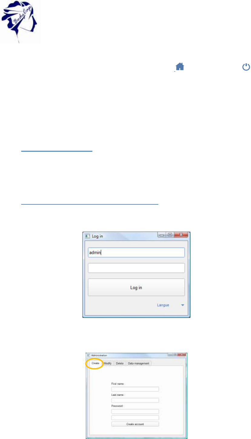
2.2.3 Configuration of account in IHM Anipill
At the first use of the application, you must log as administrator : admin is in the first area and click
on Log in.
Figure 2 : first log
With the administrator account, create a new account in “Create” tab.
Figure 3 : Account creation
10
V.01 21/08/2015
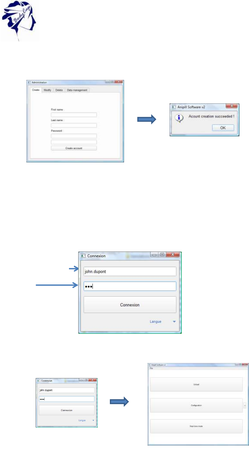
The area to complete are : first name, Last name, and twice the password. Then click on “Create
account”.
To enter in your account, close the windows. Enter your identifiant.
First name.Last name
Password
Figure 4 : Step to create account
Figure 5 : Log as user
Figure 6 : The main man of Anipill software
11
V.01 21/08/2015
A menu allows to unload data from the monitor, to configure monitor, to view data from monitor in
real time mode.
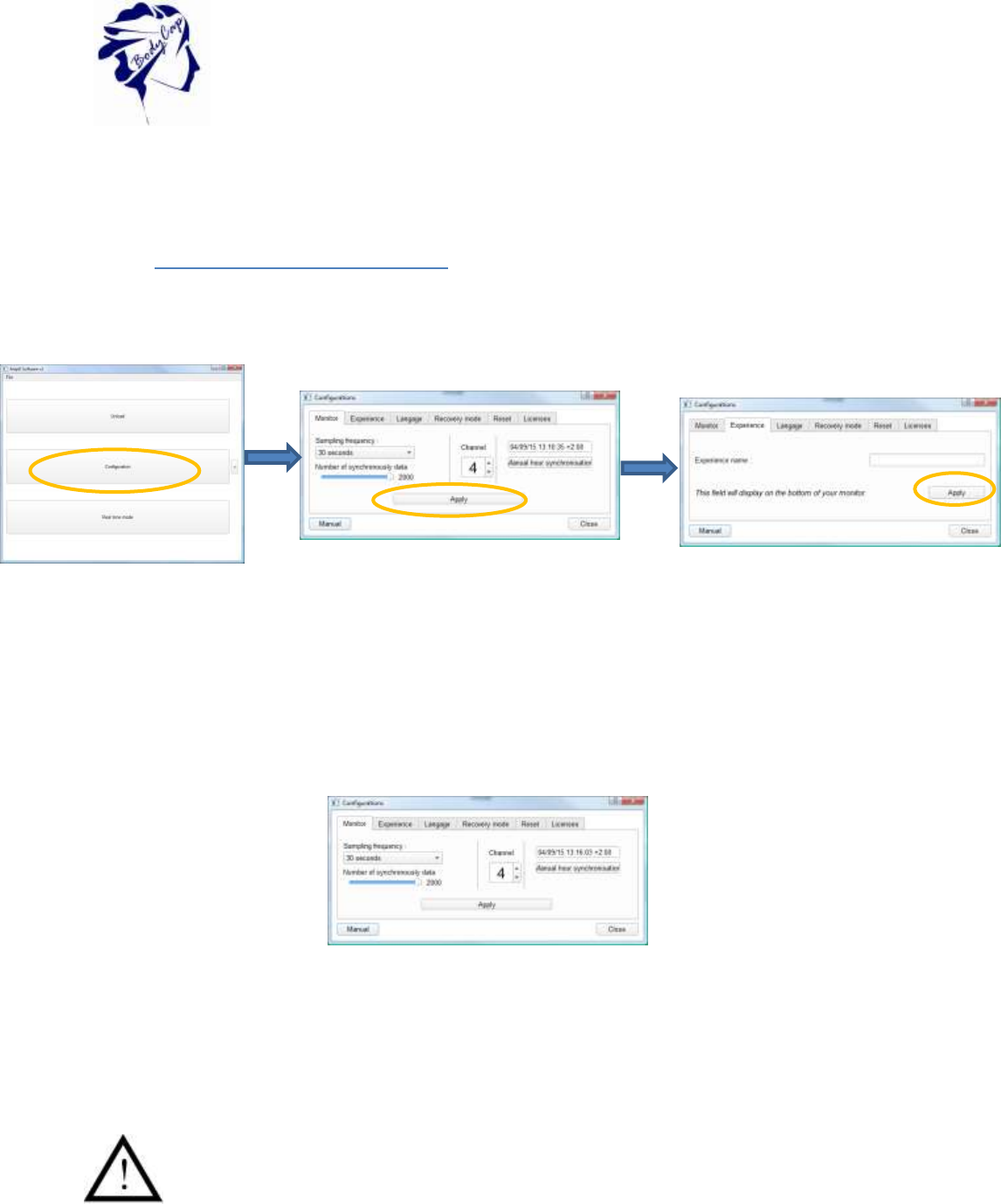
2.2.4 Configuration of the monitor
Connect the monitor to a computer having the installed Anipill software and launch it. At the
opening of the first window, select "Configuration" (Fig. 2). A menu at the bottom right allows
you to select the language.
At the opening of the second window (Fig. 3) several tabs allow to configure the monitor
before using. At any instant of the configuration, you may consult the instructions by clicking
on the tab "Manual" at the bottom left of the window.
2.2.4.1 The tab monitor
The tab "Monitor" (Fig. 3) allows selecting the operation channel for the next recording
session. It is required to take care that the monitor is sufficiently supplied, and to put it on an
available channel.
The selected channel has to be different from those of the other monitors working
in the same environment.
It is possible to select one of the seven channels (1 to 7) available in the monitor.
The date and time displayed are those of the computer on which is installed the Anipill
software. This timeline is associated with stored data.
Figure 8: Start screen of e-Celsius® Manager software
Figure 9: Tabs to configure the monitor
Choose your frequency and your channel
name an experience
Figure 7 : Steps to configure the monitor via the
Anipill software
12
V.01 21/08/2015
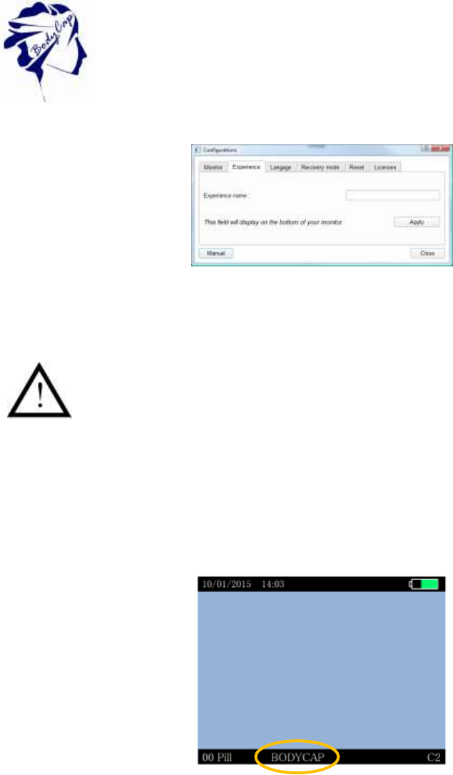
2.2.4.2 The tab Experience
Figure 10 : Tab to configure the name of experience
The name of the experience is an important element since allowing to store
data from the monitor in the Anipill software.
In fact, the name of the experience allows to store the data in a specific file. If
no name of experience has been stated before capsule activation, this step
has to be done before the data downloading from the monitor to the Anipill
software.
The tab "Experience" (Fig. 4) allows configuring a monitor for an experience. This name
appears on the monitor’s screen at the down banner.
Figure 11: Screen of Aniview monitor : experimentation name
After the configuration of each item, click “Apply”. The activation of the capsules can begin
(cf §5.8.3).
13
V.01 21/08/2015
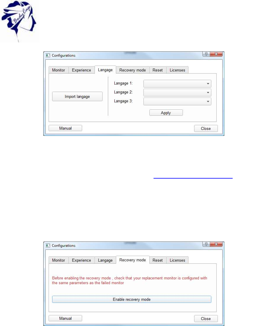
2.2.4.3 The tab language
The tab "Language" (Fig. 6) allows to import from one to three translation files on the
monitor. User can choose its preferred language on the monitor by clicking on "Apply".
Different language files are available on the website www.bodycap-medical.com. (This list is
regularly updated).
To replace the selected language among the three options stored on the monitor, please visit
the menu "Monitor" and "Language" and select the language you want to use.
2.2.4.4 The tab recovery mode
The tab "Recovery mode" is used to replace a defaulting monitor. The use of the "Replace
mode" is presented in §6.2.1.
Figure 13 Tab of the recovery mode
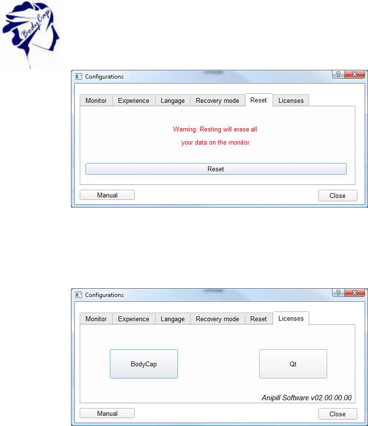
2.2.4.5 The reset tab
The tab "Reset' is used to restore the original configuration of the monitor and to delete all
the data stored in the monitor. Reset is possible only if no capsule is associated with the
monitor.
Figure 12: Item to configure the language of the monitor and the e-Celsius® Manager software
14
V.01 21/08/2015
Figure 14: Reset tab
2.2.4.6 The tab licences
The tab "Licences", allows to consult information related to used licences and the release of
the Anipill software.
Figure 15 Tab licences
15
V.01 21/08/2015
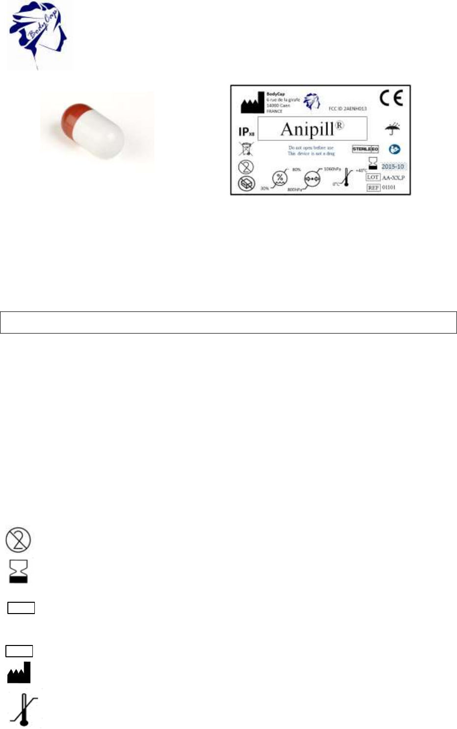
Figure 16a: Anipill capsule
Figure 16b: Label of the Anipill V2 capsule
(ref. 01102)
3 The Anipill® capsule
The capsule (Fig. 7a) is intended to be swallowed to measure gastrointestinal temperature,
for non-medical uses.
This device complies with Part 15 of the FCC Rules. Operation is subject to the condition that
this device does not cause harmful interference.
3.1 Important information and safety recommendation
The battery
The Anipill® capsule includes 4 batteries (zinc – argent oxide).
In fact, the capsule should not be disposed with the household waste.
Cleaning
It is not recommended to clean the device using hydro alcoholic solutions.
The system should not, in any case, be introduced in an autoclave on pain of permanent
damage for capsules concerned.
The label
The label contains the following symbols:
"Do not reuse"
"Use until"
"Batch code"
"Catalogue number"
"Manufacturer"
"Storage temperature limit"
LOT
REF
16
V.01 21/08/2015
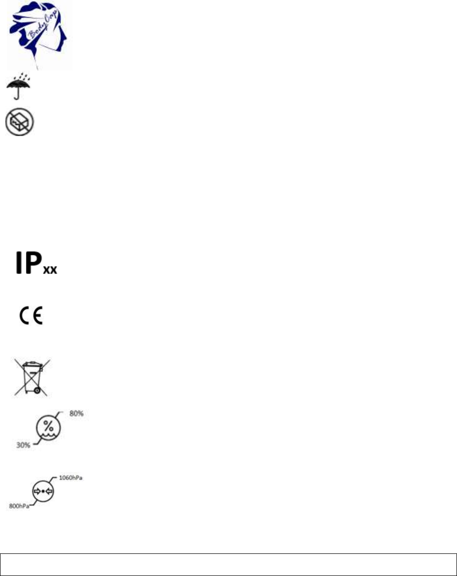
"Keep dry"
"Do not use if the packaging is damaged"
Also, the label precise the following mention:
"Do not open until the use time"
"it is not a drug"
"Protection indice"
"CE marked"
Do not put the system in municipal waste; refer to § 1.
Hygrometry level for storage
Atmospheric pressure for storage
3.2 Characteristics
Dimensions: Length: 17.7 mm.
Diameter: 8.9 mm.
Weight: ≈ 1.7 g.
Operating temperature 0°C - 50°C
range: .
Accuracy: ±0.2°C in the range 25 - 45°C.
Variability: ±0.1°C

17
V.01 21/08/2015
Sampling frequency: 30 s, 2 min, 5 min, 15 min or 1 hour ±20%. Sampling frequency
may temporary increase during data recovering.
Storage capacity (capsule): The 2000 last temperature data are stored in the capsule.
Transmission distance around 1m (environment dependant).
Between capsule and monitor:
Ingress Protection (IP): X8 (Material supporting prolonged immersion)
Power: autonomous system including zinc-silver oxyde batteries.
Battery life: Depends on the sampling frequency (1 to 12 months) (see
Figure 6: Autonomy of the capsule depends on the sampling frequency. This estimated
range is valid only when the RF communication is continuous.)
.
Communication ISM Band 433MHz - 434MHz
frequency: .
Plastic: Biocompatible PVC.
Storage life: Refer to the expiry date printed on the packaging.
WARNING: Modification of the electronic device is forbidden
18
V.01 21/08/2015
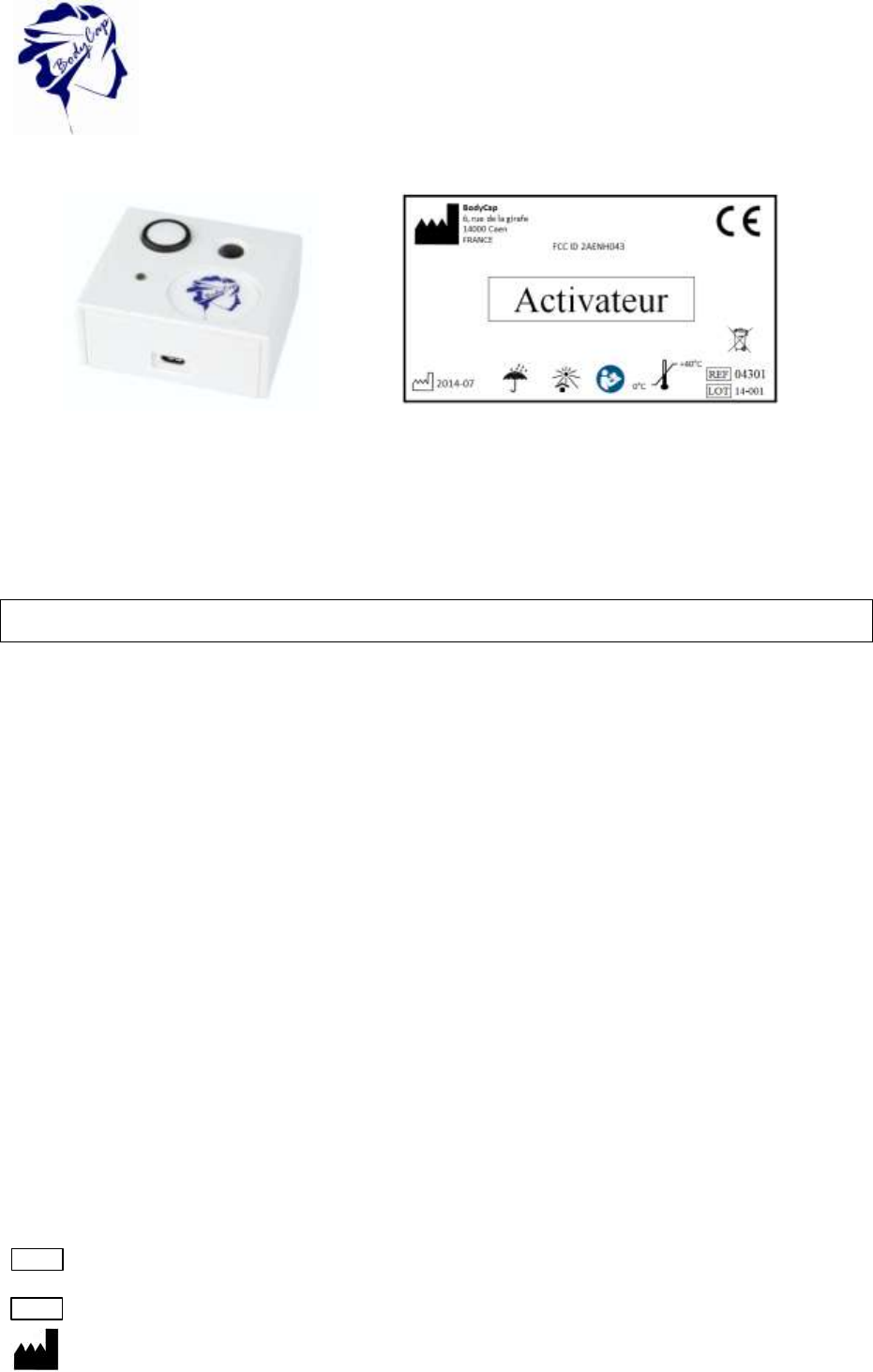
Figure 17b: Label of the Activator
4 The Activator
The Activator (Fig. 8) is intended to activate the capsule Anipill before a measurement cycle.
This device complies with Part 15 of the FCC Rules. Operation is subject to the condition that
this device does not cause harmful interference.
4.1 Important information and safety instructions
The battery
The system does not include battery. For each use, the power supply of the Activator is
performed by mains supply or a PC / MAC switched on. The connexion between the
Activator and the main supply and/or the computer has to be done only with the cables and
the power supply provided by the manufacturer.
Cleaning
If it is necessary to clean the Activator, please respect some rules. You can clean your
Activator with a damp cloth or a wipe to control the humidity. Nevertheless, it is essential to
pay attention to external connectors because they will be the most sensitive to humidity.
In any way, the system should not be introduced in an autoclave under penalty of
permanent damage.
Maintenance
It is strictly forbidden to open the activator. If a fault or malfunction is found, contact your
distributor or the manufacturer (details at the end of the user manual).
The label (Fig. 9)
The label contains the following symbols :
"Batch code"
"Catalogue reference"
"Manufacturer"
LOT
REF
Figure 17a : The activator
19
V.01 21/08/2015
"Limit of storage temperature"
"Keep dry"
"Keep away from sunlight"
"Date of production"
Also, the label precise the following mention:
"Do not put the device in municipal waste"; refer to § .
CE marked
4.2 Characteristics
Dimensions: Length: 690 mm.
Width: 590 mm.
Height: 310 mm.
Weight: ≈ 62 g.
Power supply: Main power supply unit (100 240 V) or PC via USB (5 V).
Power
consumption: 115 mW only connected (out of operation) and 500mW during
activation (for 2s).
Communication: No communication – emission of a series of electromagnetic pulses.
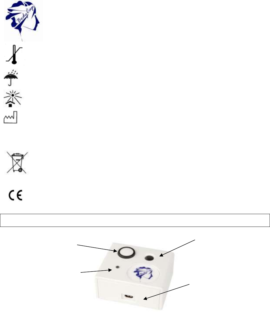
Button OK
Hole to place the
capsule
Micro-USB
connector
LED
verte
Figure 18 Desciption of the activator

20
V.01 21/08/2015
Life duration: 2 years.
Means to
disconnect from
the main supply: Unplug the power cable.
Warning: Modification of the electronic device is forbidden
4.3 The buttons
The button OK is used to launch the activation process.
The activation process is detailed in §5.8.3.
4.4 The LED
A green LED is positioned on the upper side of the Activator. This LED is continuously
switched on when the Activator is powered and flashes throughout the activation process.
When the LED is flashing, the activation process is running. During this period, it is important
to not remove/move the capsule placed in the hole.
21
V.01 21/08/2015
5 Aniview V2 monitor
The monitor (Fig. 11) is intended to communicate in RF with the Anipill capsule to recover
and store temperature data.
This device complies with Part 15 of the FCC Rules. Operation is subject to the condition that
this device does not cause harmful interference.
5.1 Important information and safety instructions
The battery
The monitor contains a Lithium-ion battery.
The monitor should not, in any case, be disassembled; the battery should not be
disconnected, or throw into fire.
To charge the monitor, please use only the cable and the adapter provided by the
manufacturer.
Cleaning
Cleaning Aniview monitor should be done within certain rules. It is possible to clean your
monitor with a damp cloth or a wipe to control the humidity. Nevertheless, it is essential to
pay attention to external connectors because these are the most sensitive to humidity.
The system should not, in any way, be introduced in autoclave under penalty of permanent
damage.
Maintenance
It is strictly forbidden to open the Aniview monitor. If a fault or a malfunction is noticed,
please contact your distributor or the manufacturer (Details at the end of this user manual).
RF Communication
In operation, it is strongly recommended to avoid putting the device on a metal table or other
metal surface that could reduce the RF emissions.
It is recommended to keep the capsule near the monitor (so it can receive data from
capsules).
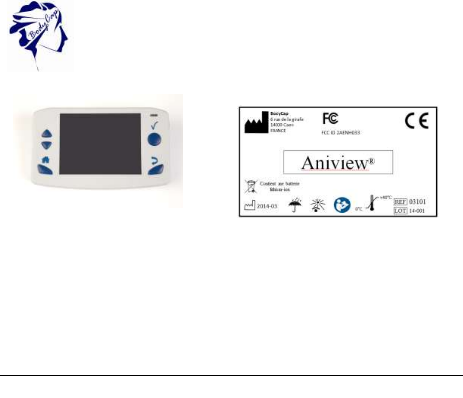
Figure 19a : Aniview Monitor
Figure 19b : Label of the Aniview ® monitor with
ref. 03102

22
V.01 21/08/2015
It is also recommended to be vigilant in environments with high metal stress (reinforced
concrete wall ...) and to regularly check on the monitor screen that the communication with
the capsule is not interrupted. In the Data Visualization menu, a star (*) associated with the
capsule number indicates that the monitor must be synchronized with the capsule. If this star
turns orange, it means that the last data has been collected more than 5 minutes ago. The
storage capacity of each capsule is limited to 2000 data, the communication between the
capsule and the associated monitor must be restored within a maximum period of 15 hours
under penalty to definitively lose some data (the automatic synchronization capsule / monitor
can take time, from several minutes to several hours depending on the number of data to be
recovered).
The label
The label contains the following symbols:
"Batch code"
"Catalogue reference"
"Manufacturer"
"Limit of storage temperature"
"Keep dry"
"Keep away from sunlight"
"Date of production"
Also, the label precise the following mention:
"Contain a Lithium-ion battery"
Do not put the device in municipal waste; refer to § 1.
CE marked
LOT
REF
23
V.01 21/08/2015
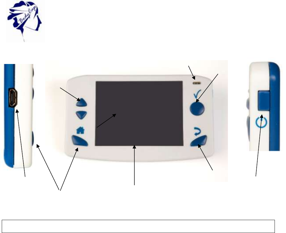
Description of the material
Figure 13: Description of the Aniview monitor
5.2 The characteristic
Dimensions: Length: 120 mm.
Width: 70 mm.
Thickness: 15 mm.
Weight: ≈ 120 g.
Screen: 320 x 240 pixels.
Operating
temperature: 0 to + 40 °C.
Storage
capacity: 100 000 data per activated capsule.
Connector: Female micro-USB.
Power supply: Battery Lithium-ion rechargeable with a main supply adapter (100
240 V) and a cable micro-USB – USB provided with the system. To
charge the system, with USB, via a computer, please install the e-
Anipill® software following the described process in this user manual.
Time to charge: 3 h.
Battery life: 36 h.
Band of
communication: ISM 433MHz 434MHz.
Screen TFT
4
LEDs
1
2
3
5
6
Micro-USB
connector
5
Figure 20 Description of the monitor

24
V.01 21/08/2015
Life duration: 2 years (or around 500 recharge cycles).
Means to
disconnect from
the mains supply: Unplug the power cable.
Warning: Modification of the electronic device is forbidden
5.3 The buttons
The monitor has got 6 buttons; the features are described below. 5 are placed around the
screen and 1 on the right side:
The button Validate (ref. 1
Figure 13: Description of the Aniview monitor )
The button Validate is used to confirm the information and to go to the menu.
The button Home (ref. 2
Figure 13: Description of the Aniview monitor)
The button Home allows to come back to the main screen of temperature data.
The button Back (ref. 3
Figure 13: Description of the Aniview monitor)
The button Back allows to come back to the previous submenu or cancel a procedure.
The button arrow up (ref. 4

25
V.01 21/08/2015
Figure 13: Description of the Aniview monitor)
This button allows navigate in the menu.
The button arrow down (ref. 5
Figure 13: Description of the Aniview monitor)
This button allows to navigate in the menu.
The button sleep-wake of the screen (ref. 6
Figure 13: Description of the Aniview monitor)
The button sleep-wake of the screen allows to switch on or off the screen.
The simultaneous use of the button sleep-wake (ref. 6
Figure 13: Description of the Aniview monitor) and the button Home (ref. 2
Figure 13: Description of the Aniview monitor) allows to switch on or off the monitor if no
capsule are associated. This mode is recommanded for the shelf storage of the monitor.
5.4 The LEDs
A yellow LED light and a red LED light are positioned on the front of the monitor; in the
upper right corner.
When the red LED light flashes, it indicates that the battery level of the monitor is low; the
26
V.01 21/08/2015
monitor must be connected to a power source. When the yellow LED light is lit, it means that
the monitor is plugged into a power source.
5.5 The battery of Aniview monitor
Information
When it is not plugged to the main supply, a rechargeable lithium-ion battery powers the
monitor. It is strictly FORBIDDEN to disassemble the monitor and to replace the
rechargeable battery under penalty to irreparable damage on the system and security
failures.
.
Charging cycle
In order to recharge the battery, simply plug the power supply of the monitor on the mains
supply and switch off the screen. Few hours are necessary to charge the battery. The battery
life of the monitor in battery operation is around 24h (screen regularly used but not
continuously).
Please do not forget to charge Aniview monitor at the end of those 24h
under penalty to lose the follow-up of all capsules in operation.
In order to leverage the risk to lose the connection between the capsules and the monitor,
the device automatically goes into a power-saving configuration (extinction of the screen and
of the RF communication with the capsules) before the total discharge of the battery. Use of
LEDS is described in following table:
Table 3 : Batteries status
Battery status
LED
Functions
Normal
-
Normal operation
Low
Red LED
flashes
Normal operation
Critical
Red LED
flashes
The screen is switched off
The RF communication is stopped
It is highly recommended, especially in the context of extended use of the material, to let
the monitor be connected to a power source during the entire operation.
27
V.01 21/08/2015
5.6 Connection
Female Micro USB port
This connector is located on the left side of the monitor. It is possible to use the micro-USB
port to connect the monitor to the mains supply via the cable and adapter provided by the
manufacturer or directly to a computer. Use of connector are:
(i) to set up the monitor (date, time, channel, alarm thresholds, patient data)
(ii) to download data from the monitor to Anipill IHM Software
(iii) to visualize the results of measurements,
(iv) to export them to PDF or spreadsheet format
(v) to recharge the battery monitor.
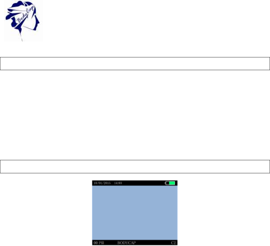
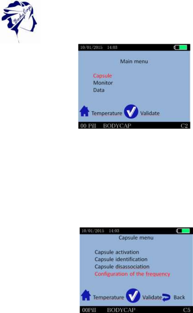
5.7 Menus of the Aniview monitor
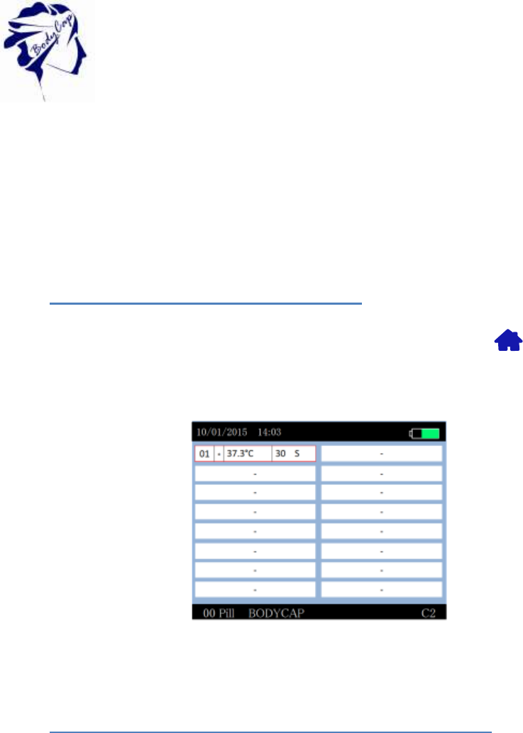
Figure 21 Screen of the Monitor including general information
Regarding the level of the menu in which the user is, the monitor screen indicates some
general information including:
Date (eg 10/01/2015)
Time (eg 14:03)
The battery level of the monitor (eg the top right of the screen)
The operating channel of the monitor (eg C2)
A field corresponding to a patient identification (eg User BODYCAP)
The number of capsules associated (eg Caps 0)
View of the main menu of the monitor (Fig. 15)
28
V.01 21/08/2015
Figure 22Main menu of monitor
To validate a menu and to move to a submenu, press the button OK
(§ 6.4).
To come back, press the button Back (§ 6.4).
To return directly to the temperature display, press the button Home (§ 6.4).
Navigation between the menu items is possible by using the up - & down buttons (§ 6.4).
Capsule Menu
The menu Capsule (Fig. 17) brings together the different control functions of the capsules.
Figure 23 Capsule Menu
Capsule activation: Starts the activation process of the capsule.
Capsule Identification: Allows to visualize the ID number of associated
capsules.
Capsule Disassociation: Allows to prepare the release of a location (after data
unloading) and switch off the capsule.
Configuration of the frequency Alllows to modify the frequency
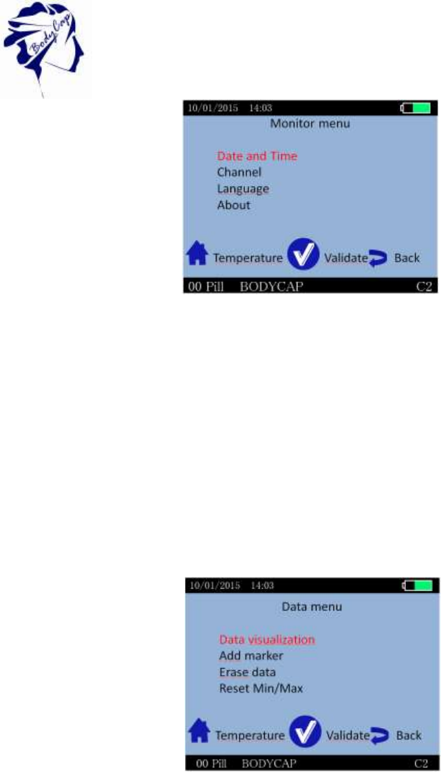
Monitor menu
The MONITOR menu is used to manage the monitor configuration (Fig. 18).
29
V.01 21/08/2015
Figure 24 Monitor Menu
Date and Time: Allows to set time zone, date and time
Channel: Allows to set the channel.
Language: Allows to change language
About: Allows to visualize the software release number and
serial number of the monitor
The Data menu
The Data menu is used to visualize the latest temperature data from the associated
capsules. (Fig. 19).
Figure 25 Data menu
Data visualization: Allows to visualize the last collected data as well as the
minimum and maximum values collected by each
associated capsule.
Add marker: Allows to add an event marker which will appear in the
graph available on Anipill® and the data file when
exporting.
Erase data: Allows to erase data from monitor ( All data or one
capsule)
Reset Min/Max Allow to reset the Min/Max value from monitor
30
V.01 21/08/2015
5.8 Main functions
5.8.1 Set the monitor
To set the monitor, please connect it to the computer via USB to use the IHM Anipill
software.
You may also configure:
date and time,
operating channel and.
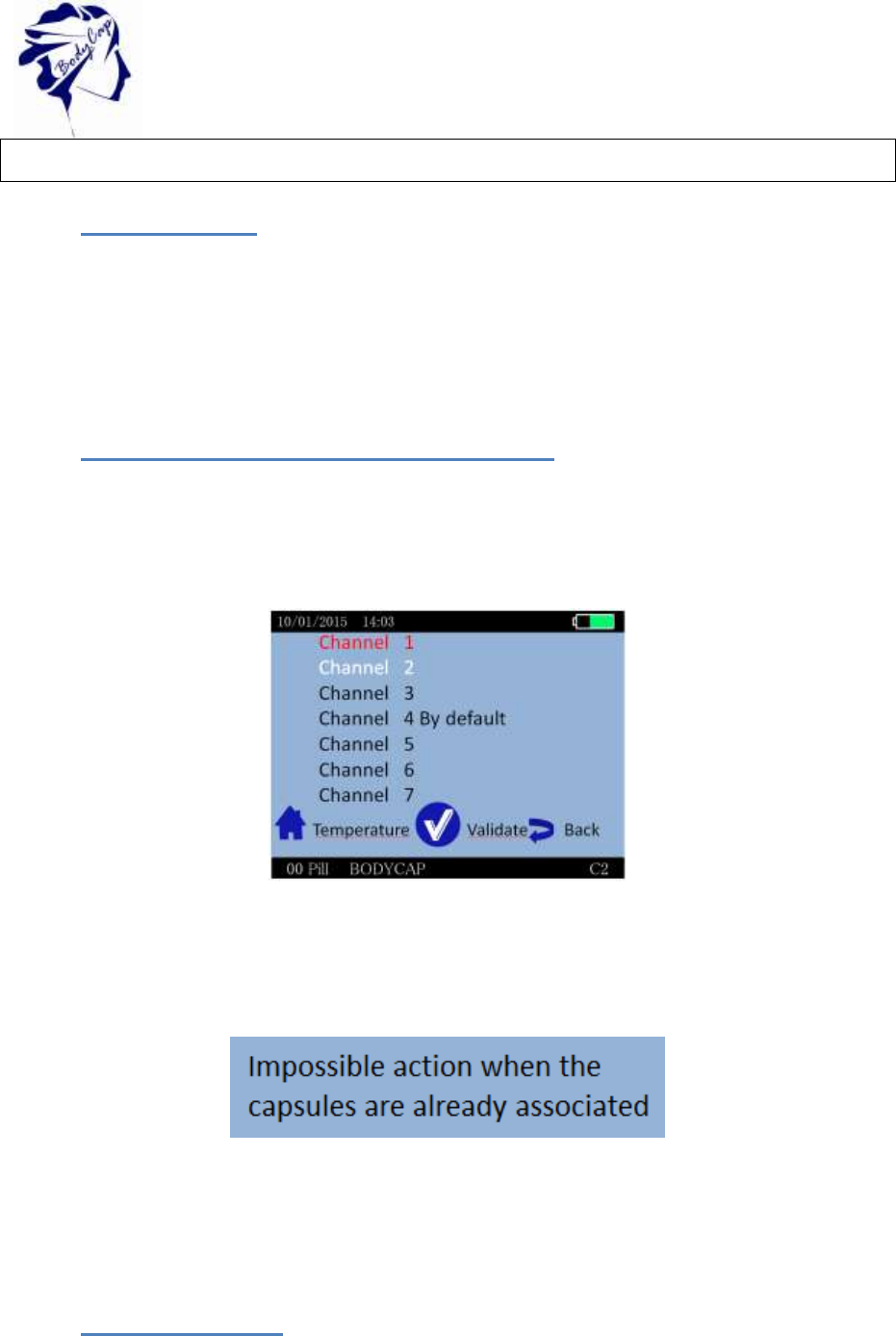
5.8.2 Changing the channel used by the monitor
Up to 7 monitors can operate in parallel, in the same environment, thanks the choice
between 7 different communication frequency channels.
This choice can be performed through the Anipill® software or manually on the monitor. To
set the operating channel on the monitor, go to the menu "MONITOR" and the submenu
"Channel". Select a channel not used by monitors located in the same environment.
Figure 26 Menu to set the channel
This command is not possible when capsules are associated with the monitor.
The following message appears on the screen:
Figure 27 error message
Think about recording the working channel of each monitor; in case of breakage or failure,
this information will be needed to launch the monitor replace procedure (cf §6.2.1).
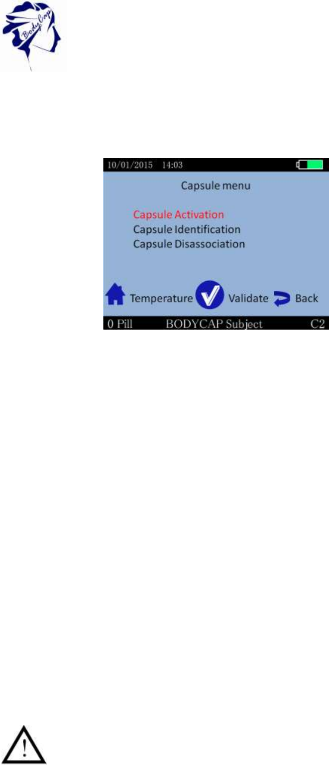
5.8.3 Activate a capsule
Note: Before capsule activation, please check the monitor's operating channel,the date/time
and the experimentation name.
31
V.01 21/08/2015
No modification of these three parameters will be authorized after activation of a
capsule.
Please set the alarm threshold before capsule activation.
In order to activate a capsule, please go to the "PILL" menu and then the submenu "Capsule
activation" of the monitor (Fig. 22).
After validation of the command "Capsule activation", dialog boxes will guide you through the
activation process:
First, the message "Connect activator" appears on the monitor screen; after
connecting the activator and placing it close to the monitor (<1m), press the button
OK as soon as button appears.
Then the message "Turn the capsule, small part down" appears. The capsule to
activate has then to be placed in the hole of the activator, big part upwards.
Then press the button OK on the monitor.
Finally, the message "Association in progress ... Press the button on the activator"
appears. You must then make a short press on the button of the activator.
Once the button of the Activator activated, the green LED located on it will flash; then
leave the capsule in place and wait until you see the message "Capsule activated, ID
number: XX.XX.XX.XX" on the monitor screen. It is recommended to note this ID
number.
Therefore, the capsule is activated and associated with the monitor. Press OK to confirm the
announcement and come back to the Capsule MENU.
Monitor assigns to the capsule a number between 1 and 16, the reference for data display.
By default, the assigned number will always be the lowest available between 1 and 16
(available mean that there are no associated capsule or stored data associated with this
number).
If the LED of the activator stops flashing and the message "Error! Would you
like to repeat the activation process" appears on the monitor screen, please
check the positioning of the Anipill® capsule in the hole of the Activator and /
Figure 22: Capsule activation menu
Figure 28 : Capsule menu
32
V.01 21/08/2015
or slightly move the Anipill® capsule in the hole, press the button OK on the
monitor to restart the association process and re-press then the button on the
Activator.
For the activation of an additional capsule, repeat the procedure. It is possible to connect up
to 3 capsules in parallel with a single monitor.
5.8.4 Consult temperature data in real time
In order to visualize the collected temperature data, go to the menu "DATA" and the
submenu "data visualization" or directly by pressing the button Home . The screen will
then allow you to visualize the latest temperature data collected for each activated capsule
and the minimum and maximum values collected by each associated capsule.
Figure 29 : Home screen menu of data visualization
5.8.5 Synchronization of the data in memory of the capsule
It is recommended to be vigilant in environments with high metal stress (reinforced concrete
wall ...) and to regularly check on the monitor screen that communication with the capsule is
not disturbed.
In the menu "View Data", a star (*) associated with a capsule number indicates that the
monitor have to be synchronized with the capsule. An orange star means that the last data
have been collected more than 5 minutes.
The capsule has an internal memory that automatically records the last 2000 measurements
collected. When communication between the monitor and / capsule (s) is interrupted
(indicated by the star on the temperature display screen), the monitor is not receiving / the
data (s).
Nevertheless, there is a feature in the monitor that automatically recovers the missing data
as soon as communication is restored. The monitor will automatically synchronize its data
with the 2000 data available in the memory of the capsule.
33
V.01 21/08/2015
The storage capacity of each capsule is limited, the communication between the capsule and
the associated monitor have to be restored within a maximum period of 15 hours. If not, you
might permanently loose some of the collected data (automatic synchronization capsule /
monitor can take time, from several minutes to several hours depending on the number of
data to recover).
If data are synchronized without initial data (which is the case in Backup mode), the time and
date associated to the data will be estimated. It is possible that of an inaccuracy of a few
minutes occurs for the estimated time.
A marker "Backup mode" green on the chart of the Anipill software indicates the beginning of
the Backup mode. All the data before this marker are synchronized data.
5.8.6 Visualization of the end-of-life of the capsule
On the monitor, when a capsule reaches the end of life, the message "Low" appears in the
column Batt (Fig. 27) of the detailed visualization screen (§6.9.4).
The capsule will stop around 500 steps after the appearance of the first message "Low" (if
the monitor and the capsule are in continuous RF communication).
5.8.7 Disassociation of a capsule
After usage, just go to the menu "PILL" (Fig. 22) of the monitor and in the submenu
"Disassociation capsule", select the capsule to stop and press OK.
In order to ensure the success of the procedure, the capsule and monitor must be close
enough to communicate.
Figure 30: Selection of a capsule to disassociate.
A confirmation has to be validated before the disassociation of the capsule. This
action is definitive; the capsule disappears from the Monitor database. The data
file corresponding to the capsule is stored until data download to a computer and
activation of a new capsule on this location.
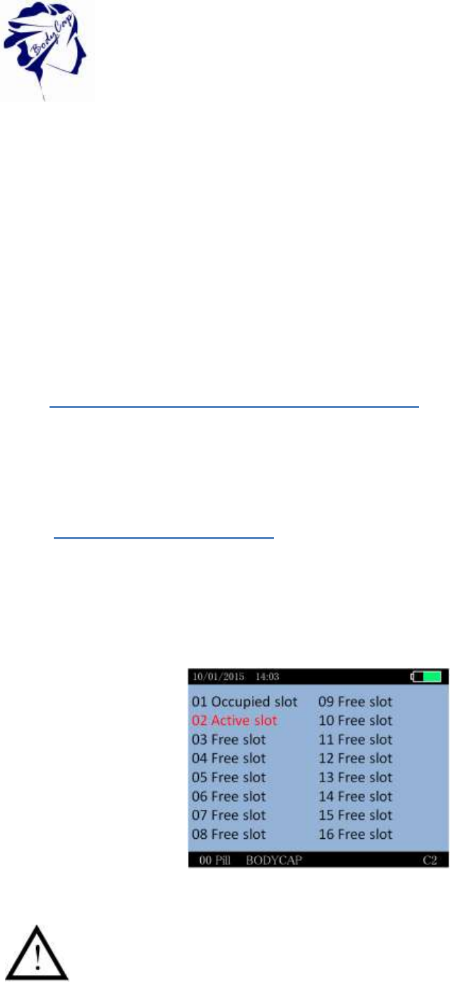
Three cases may be display:

34
V.01 21/08/2015
"Occupied slot ": The data of a capsule remains on the monitor, but the capsule is no
longer associated. Data can be downloaded on the Anipill software. As unloading did
not take place, a new capsule cannot be activated on this location.
"Active slot": A capsule is associated
"Free slot": This location is available to the activation of a new capsule.
5.8.8 Use of the monitor screen
In order to save battery, the monitor screen will switch off automatically after 3 minutes of
inactivity when the monitor is in battery operation. This action is canceled for 3 possible
reasons:
The monitor is power supply mode. In this case, the screen is constantly switched on
without user action.
The monitor displays data temperature screen. This screen is very important for patient
monitoring. In this case, the monitor does not automatically go into standby.
If the monitor is in standby mode and that a physiological alarm triggers, the monitor
will automatically switch on and will go on the temperature display.
In any case, to go or to come back to standby mode, you may simply press the side button of
the monitor, represented by the following logo:
5.8.9 Low battery
The monitor has a limited autonomy depending on usage (screen on / off, an alarm triggered
or not etc ...).
Therefore it is important to always check the battery level of the monitor when using the
monitor in battery mode. The orange LED allows you to be notified when the battery of the
monitor is in a critical state while you need to plug it in USB ASAP.
If not, however, the monitor is switched off without being recharged on time, you simply have
to put the monitor in charge (you may have to wait a few minutes before you can use the
screen again), and reset immediately the time on the monitor.
Indeed, the radiofrequency part will restart only when the time of the monitor has been reset.
Warning, if an invalid time is entered, the data may be corrupted.
This action of setting the time may be done directly on the monitor or through the Anipill®
software.
While the battery is in charge, the battery logo turns purple and always filled (indicating the
state of charge and not the battery level). Once the cable is disconnected, the logo becomes
green and shows the real percentage of the battery.
6 Anipill® software
Anipill® software is designed to visualize and export temperature data from a measurement
cycle.
6.1 Main fonctions
35
V.01 21/08/2015
To use the Aniview monitor with Anipill software, you must install the application and
the BodyCap drivers (provided on the USB key BodyCap). When the installation is
completed, the monitor and the application may automatically interface.
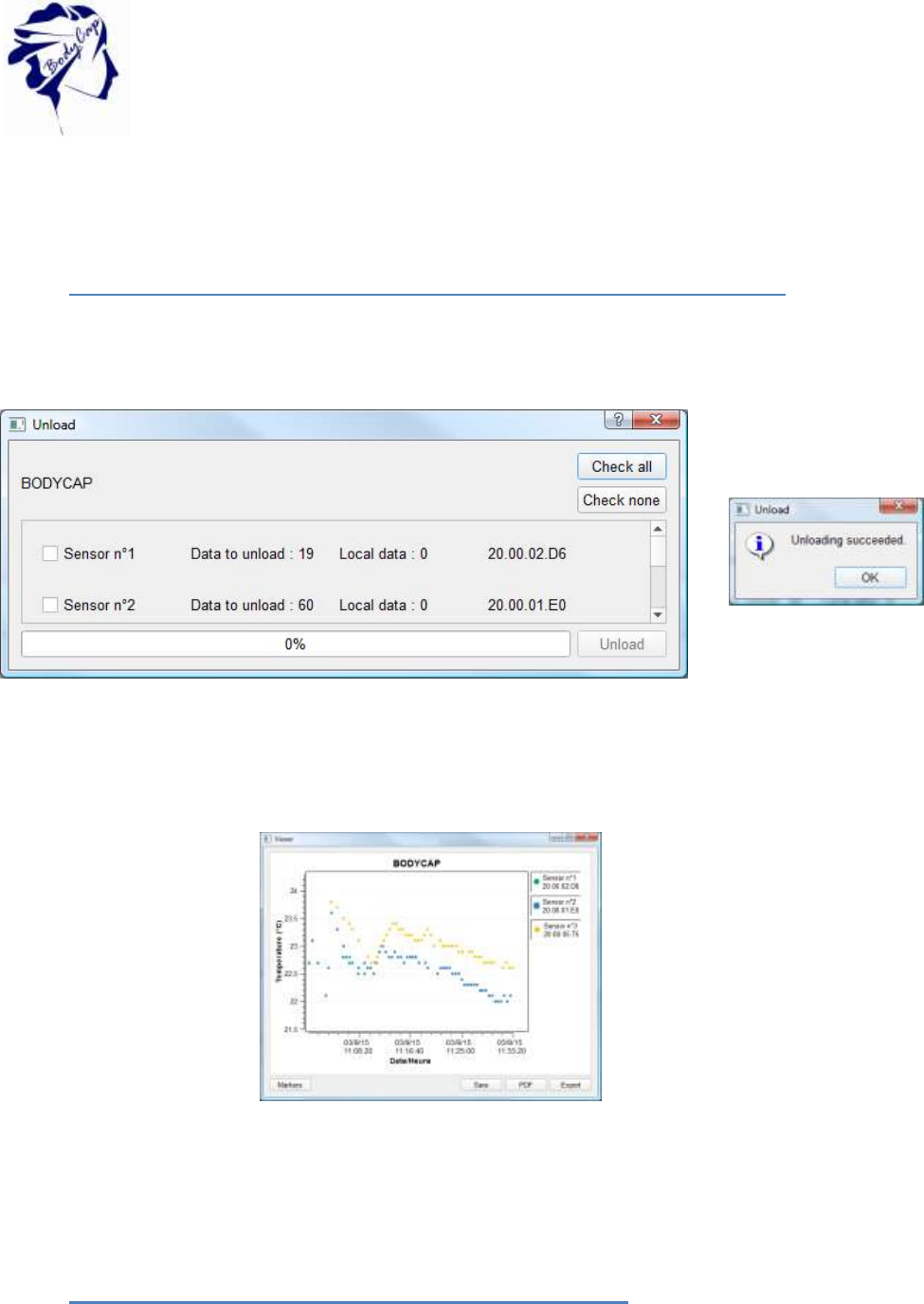
6.1.1 Unload and consult the temperature data on the Anipill software
On the main screen of the Anipill software, select the menu "Unload" (Fig. 2). An unloading
progress window appears.
Figure 30 : Caspule to download in the software and the validatiopn message
To download data from capsule, select capsule or all capsules (“Check all”) and click on
“Unload”.
Figure 31 : Picture of the curves obtained on the Anipill® software after the data unloading.
It is possible to move on the graph by keeping key Alt pressed and clicking the left mouse
button to have the entire curves.
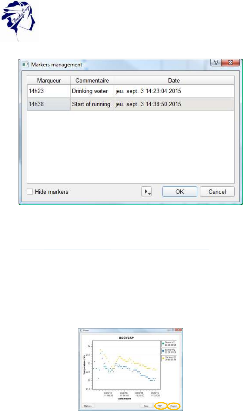
6.1.2 Visualization of markers from the Aniview monitor
The data unload includes markers indicated during the registration period and displayed by a
vertical black line. These markers may be named by clicking on the box "Markers"; a window
appears to name them. For this purpose, just select the line for the desired marker, fill the
36
V.01 21/08/2015
corresponding fields and confirm by clicking OK. They are displayed with corresponding
names.
Figure 32 : Screen of marker management
If you do not want to see all the markers, you can check the "Hide Markers" at the bottom
left.
6.1.3 Export temperature’s data unloaded on Anipill software
To export temperature’s data, one curve or more may be selected from the icons at the top
right of the screen, shown in Fig. 28.
To export curves as displayed on the screen of the software, a PDF file may be generated
with the "PDF" button (Fig. 26). The view from the graph in the exported PDF file is the
display for the graph (with the same zoom and the same number of curve).
A data file in spreadsheet format can be generated from the "Export" button. A spreadsheet
including the temperature data, the date and time of recording and the markers will be
generated automatically.
Figure 33 : Graph and buttons to export data
37
V.01 21/08/2015
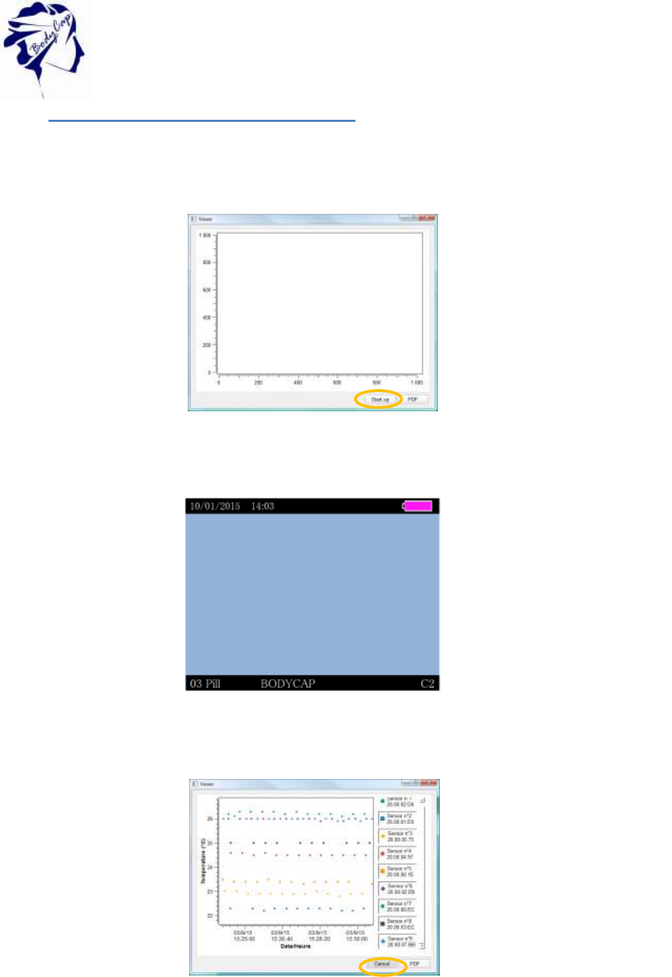
6.1.4 Consult temperature data in real-time
It is possible to view the collected data temperature in real time via the ANIPILL® PC
software.
To do so, first, check if the monitor is turned on and if it is already associated with the
capsules.
Connect the monitor with the USB cable to a PC. Click on “Real time mode”
Figure 34 : Real time mode
The monitor is not avaible so the screen is a blue one.
Figure 35 screen of monitor during the real time mode
For a monitor (with 9 associated capsules), the viewer shows the following graph.
.
Figure 36 Screen to stop the real time mode
When your experience is over, click on “Cancel”
To stop the real time,
click on cancel
38
V.01 21/08/2015
6.2 Secondary functions
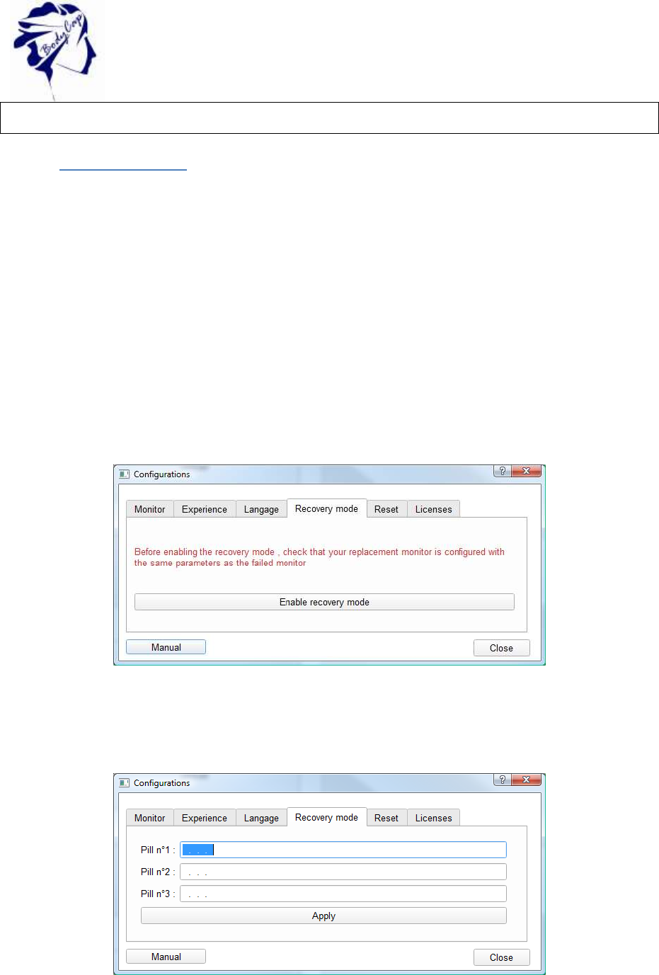
6.2.1 Recovery mode
When the operation of the monitor is disturbed (failure, broken, …), it is possible to recover
the communication with capsule which was associated first; via an another monitor. This
allow to ensure the continuity of the cycle of measurement
It is necessary to start the replace operation with an operational monitor. This mode will allow
to retrieve data from all the Anipill capsules communicating on the selected channel, in the
communication frequency of the monitor and whose ID number is known.
First, it is necessary to bring a functional and charged monitor. Then, check that no capsule
is associated with this monitor. Connect it to the Anipill® software and configure the
operating channel of the monitor to the same channel as the failed monitor. In fact on the
operating channel of the capsules you want to recover [follow the procedure in § 5.8.2]. After
you have started the Anipill® software, connect the monitor to a functional PC/Mac with the
cables provided by the manufacturer. Select "Recovery mode" on the Anipill® software.
Figure 37 Tab "Replace mode"
Validate the start of the mode by clicking "Enable recoveryFrecover mode".
The following window appears:
Figure 38 Id of capsules in recovery mode
Enter the ID number of the capsules you want to recover. (§ 6.9.12)
The order of capsules does not matter.
39
V.01 21/08/2015
Warning: all the capsules must have been first activated with the same original monitor.
Select “Apply”. You will see the banners of the monitor switch from black to white, indicating
the use of the replace mode.
Place the monitor close to the environment of the capsules to recover. The monitor will
automatically resynchronize with the capsules that are still close and will match the entered
ID number in the Anipill® software.
To exit the replace mode, you have to disassociate the capsules of the monitor (§ 6.9.12)
and download the data via the Anipill® software.
Note: To exit the recovery mode, connect the monitor to a PC with the cables provided by the
manufacturer and go again to the tab Backup mode on the Anipill software. Click then on
"Disable the Backup mode." Banners on the monitor switch then again in black, indicating
that the replace mode is stopped.
For the data which are saved in the capsule before the recovery mode, the frequency cannot
be known. So the associated frequency is by default the same that the one entered.
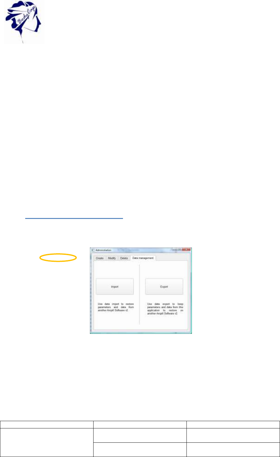
6.2.2 Export and import accounts
To export all accounts from an comptur to an other, click on “Data management” tab with the
administrator account. Export account with the “Export” button, name and save the file.
Figure 39 : Data manegement Tab
On the other computer, log as administrator and click on “Import” button in order to download
the file. All previous accounts will replace by the imported accounts.
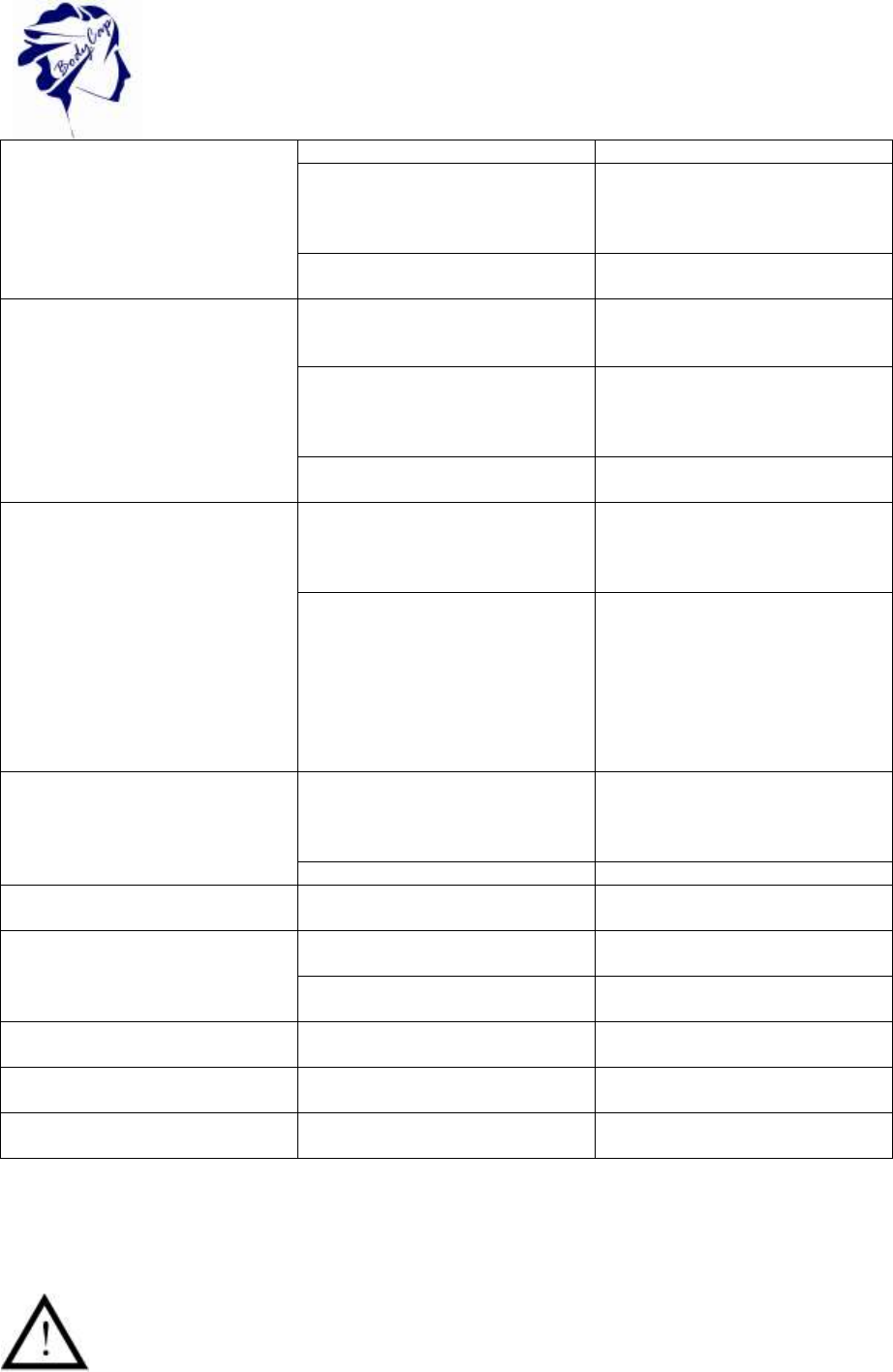
7 Failures guide
Tableau 4 : Failures guide
Problem
Probable cause
Solution
The monitor does not switch on.
Monitor in sleep mode
Check that the monitor is not in
sleep mode or deep sleep mode
The battery of the monitor is
discharged
Connect it on the mains supply and
wait few minutes before interacting
40
V.01 21/08/2015
the monitor (on the mains supply)
The monitor is in end of life
The manufacturing date is printed
on the label. The proper operation
of the monitor is warranted for 500
recharges cycles.
The monitor may require a
maintenance action
Return to your distributor or to the
manufacturer.
The LED of the activator does not
switch on.
The activator is not property
connected
Ensure that the connections are
correct and the power outlet has
power
The activator is in end of life
The manufacturing date is printed
on the label. The proper operation
of the activator is warranted for 2
years
The activator may require
maintenance action
Return to your distributor or to the
manufacturer
The RF communication between
monitor and capsule is not
working.
The distance is too large
Ensure that the capsule is in the
range of the monitor, check the
date of the last temperature data
received.
The capsule is not associated
Respect the activation process.
If the association is difficult,
ensure that the capsule is close
enough to the monitor or please
turn the capsule in the hole of the
activator.
The monitor indicates the number
of associated capsule.
Inappropriate autonomy of the
monitor
Non-recharged battery
Connect the monitor to the mains
supply and wait few minutes
before interacting with the monitor
(on the mains supply).
Battery in end of life
Scrap it to a DEEE organism.
Inappropriate autonomy of the
capsule
Old battery
Check the date printed on the label.
The connection between the
monitor and the PC/MAC do not
work.
Incorrect connection
Check that the cable is properly
connected.
The monitor may require a
maintenance action
Return to the manufacturer
The green LED of the monitor
does not switch on or blink.
Check the power supply
Association to the capsule does not
work.
3 capsules maximum per monitor
Check that a location is free on the
monitor.
Frozen screen.
The monitor may require a
maintenance action
Return to the manufacturer
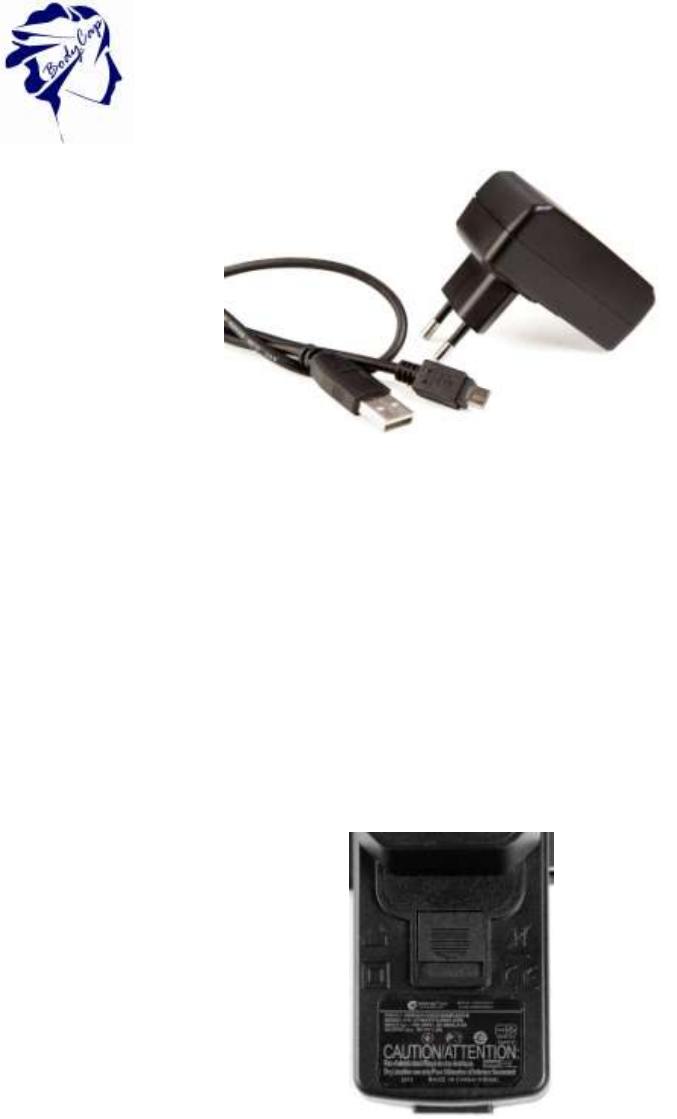
8 Cables and power supply
Two cables are supplied with the system: two USB - micro-USB cables which allow
to connect the monitor to a computer to download data or power the monitor and/or
the activator by connecting them to a computer on or sector through the adapter.
41
V.01 21/08/2015
Figure 35: Cable and mains supply adaptor
Only cables provided by the manufacturer should be used to ensure proper operation and to
not deteriorate the system.
The power supply for this device has the following characteristics:
Brand: GLOBTEK (HONG KONG) LTD
Model: GTM41078-05-USB
The power supply is the means for external insulation of the electronic device.
Data plate:
Figure 36: Power supply data plate