Bosch Automotive Service Solutions 576253 WiFi/BT Module Card User Manual Antenna list for Module Integration and antenna spec
Bosch Automotive Service Solutions Inc WiFi/BT Module Card Antenna list for Module Integration and antenna spec
Contents
- 1. User manual
- 2. Antenna list for Module Integration and antenna spec
- 3. User Manual
- 4. Antenna List for Module Integration and antennas spec
- 5. Users manual
Antenna list for Module Integration and antenna spec

Bosch Automotive Service Solutions Inc
Antenna List for Module Integration - for Module PN 576253.
FCCID: 2AHLA-576253
ICID: 4811A-576253
This module has been granted modular approval for mobile applications. OEM integrators for host
products may use the module in their final products without additional FCC / IC (Industry Canada)
certification if they meet the following conditions. Otherwise, additional FCC / IC approvals must be
obtained. (Note: This module is not being sold commercially to any OEM, Bosch Automotive
Service Solutions will exclusively utilize this module within our products.)
The Following is a list of Approved Antennas for use in integration into a product:
Taoglas Antenna Solutions - Part Number: FXP840.07.0155B
• Antenna Type: Flexible-Poly Material Antenna. Monopole. Dual-band 2.4GHz / 5GHz.
• Antenna Gain: The maximum antenna gain including cable loss in a mobile-only exposure
condition must not exceed 2.5dBi at 2.4GHz and 2.5dBi at 5.8GHz (Peak Gain).
• Antenna Mount: Adhesive Backed for mounting on inside of product plastic housing.
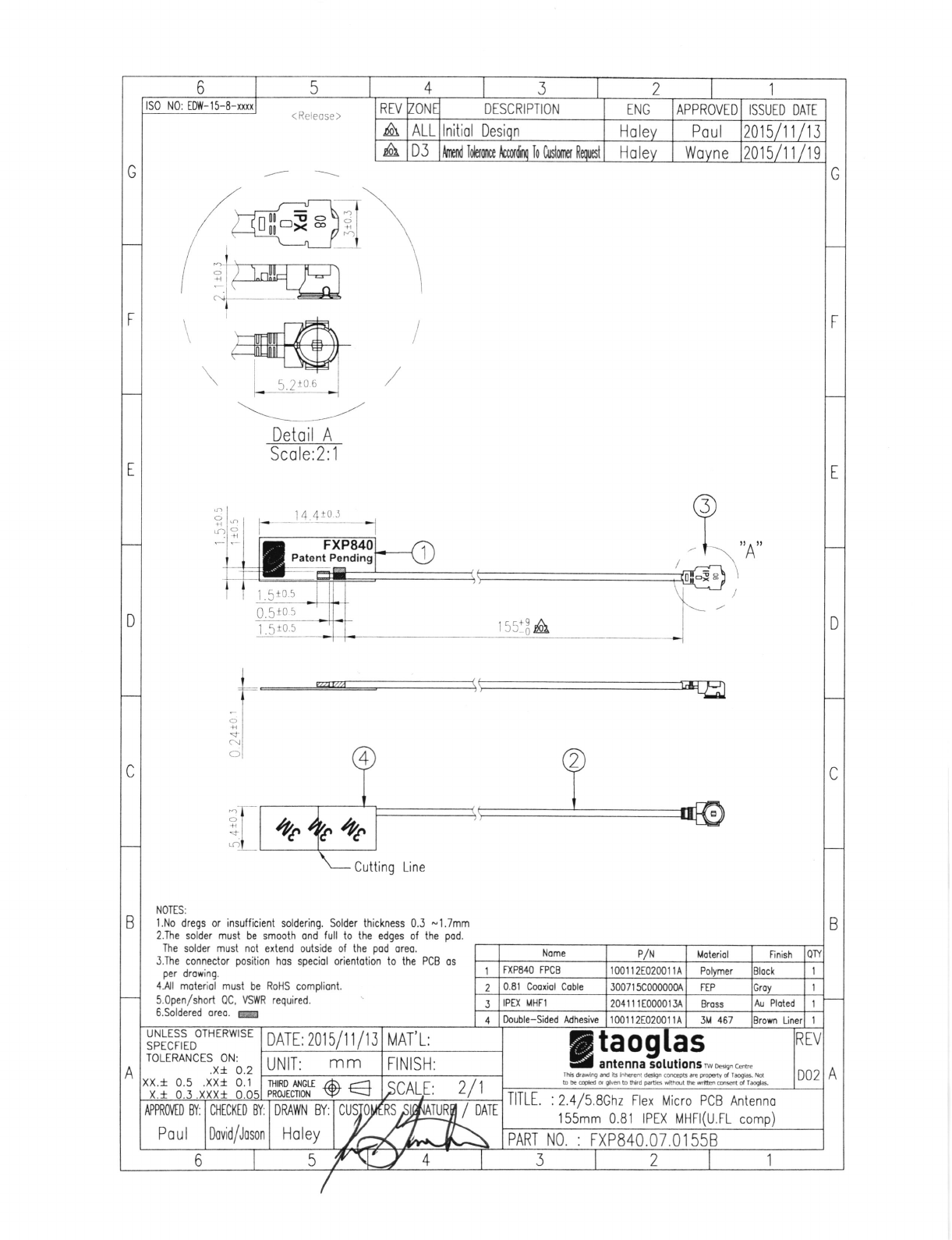
• Antenna Connector: IPEX MHF1 Connector (U.FL compatible connector), 155mm cable length.
Yageo Phycomp - Part Number: ANTX150P111B24553
• Antenna Type: PCB Antenna. Monopole. Dual-band 2.4GHz / 5GHz.
• Antenna Gain: The maximum antenna gain including cable loss in a mobile-only exposure
condition must not exceed 3.2dBi at 2.4GHz and 3.4dBi at 5.8GHz (Peak Gain).
• Antenna Mount: Adhesive Backed for mounting on inside of product plastic housing.
• Antenna Connector: IPEX MHF1 Connector (U.FL compatible connector), 150mm cable length.
The final host / module combination may also need to be evaluated against the FCC Part 15B criteria for
unintentional radiators in order to be properly authorized for operation as a Part 15 digital device.
If the final host / module combination is intended for use as a portable device the host manufacturer is
responsible for separate approvals for the SAR requirements from FCC Part 2.1093 and RSS-102.

Document No. DE0095 Rev 5
Bosch Automotive Service Solutions
Print Date: 8/24/2015 Bosch Automotive Service Solutions Confidential 1 of 1
QMS electronic document is the controlled copy
Standard E-Item Initiation Form
Date:
E-Item (Bosch Part Number):
Description:
Project Number: Annual Usage:
Product Type: Moisture Level:
Item Group:
Sales Statistics Group:
Administrative Change #
Approved Mfg: MFG P/N: A/D: ROHS: T/R:
Notes:
Originator/Engineer: Component Engineer
Approved:
577310
Antenna,Dual Band, 2.4G/5.5G
308721
5000
HAA
221330
AHD
Add
Taoglas
FXP.840.07.0155B
Add
Add
Add
Add
Add
Add
Nissan MIT and GT2 Projects
Eric Vande Zande
Kevin Gunther 9/17/15
N/A (Not Applicable)
9/17/15
SPE-12-8-115/E/EZ Page 1 of 15
SPECIFICATION
PATENT PENDING
Part No. : FXP.840.07.0055B
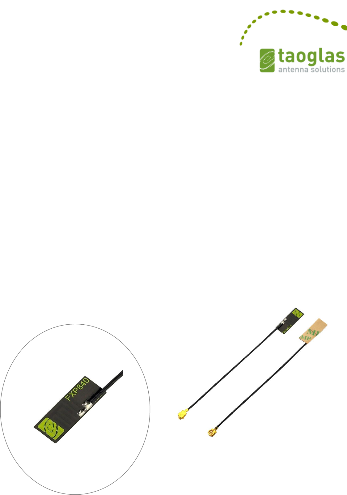
Product Name : FXP.840 Freedom Series
Super Small Monopole
Dual-band 2.4 GHz /5 GHz Antenna
Features : Flexible and Tiny - Ultra Low Profile 14mm*5mm*0.1mm
2dBi Peak Gain
Adheres directly inside of product plastic or glass housing
Form factor and cable routing convenient for integration
IPEX MHF1 Connector (U.FL compatible)
55mm Ø 0.81mm mini-coaxial cable
Customizable cable and connector
RoHS Compliant

SPE-12-8-115/E/EZ Page 2 of 15
1. Introduction
The patent pending FXP.840 is a super small monopole ultra-low profile antenna for 2.4/5
GHz bands that includes Bluetooth and Wi-Fi dual-band application. The FXP.840 has a peak
gain of 2.5dBi at 2.4GHz and efficiencies of 40%, and 2.5dBi gain and 53% efficiency at
5.8GHz.
This Taoglas patent pending antenna is unique in the market because it is made from poly-
flexible material, has a tiny form factor (14mm*5.0mm*0.1mm) and has double-sided 3M
tape for easy “peel and stick” mounting.
The cable routes conveniently directly out of the bottom of the antenna, reducing the volume
the antenna takes up in the device to an absolute minimum compared to other designs. The
FXP.840 is the ideal all-round antenna solution for fitting into narrow spaces and still
maintaining high performance, for example on the inside top or adjacent side applied directly
to the plastic housing of LCD monitors, tablets, smartphones.
The cable and connector are customizable according to customer requirements.
Many module manufacturers specify peak gain requirements for any antennas that is to be
connected to that module. Upon testing of any of our antenna with your device and a
selection of appropriate layout, integration technique, or cable, Taoglas can make sure any of
our antennas peak gain will be below the peak gain requirements. Taoglas can then issue a
specification and/or report for this selected WiFi antennas in your device that will clearly show
it complying with the peak gain requirements, so you can be assured you are meeting
regulatory requirements for that module.
It is better not to select an embedded antenna with very low free-space peak gain (<2dBi)
directly, as this antenna would have worse performance in your device, and lead to
compromised performance compared to using a Taoglas antenna.

SPE-12-8-115/E/EZ Page 3 of 15
2. Specification
ELECTRICAL
Antenna
FXP.840
Standard
2400 MHz
5800 MHz
Operation Frequency (MHz)
2410-2490 MHz
4900~5800 MHz
Polarization
Linear
Linear
Impedance
50 Ohms
50 Ohms
Max VSWR
2:1
2.5:1
Max Return Loss (dB)
-10
-7.0
Peak Gain (dBi)
2.0
2.5
Efficiency (%)
40
53
Average Gain (dB)
-3.9
-2.8
Radiation Properties
Omni
Omni
Max Input Power
2W max
2W max
* The FXP840 antenna performance was measured on a 30x30 mm 2.0”ABS plastic plane.
MECHANICAL
Dimensions (mm)
14 x 5.0 x 0.1
Required Space (mm)
14 x 5.0 x 0.1
Material
Polymer
Connector
IPEX MHF1
ENVIRONMENTAL
Operation Temperature
-40°C to 85°C
Storage Temperature
-40°C to 85°C
Relative Humidity
40% to 95%
RoHs Compliant
Yes
SPE-12-8-115/E/EZ Page 4 of 15
3. Antenna Characteristics
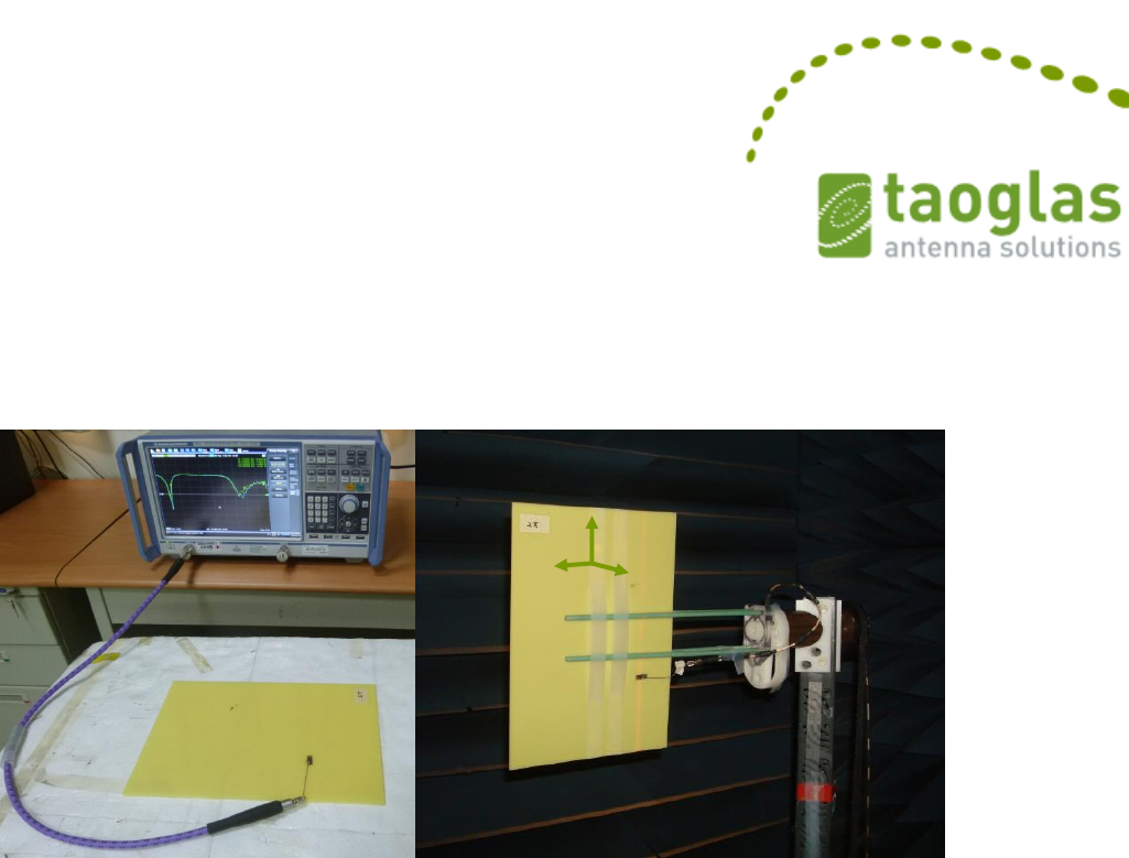
3.1 Test set-up
Figure 1. Impedance measurements (left side) and peak gain,
efficiency and radiation pattern measurements (right side).
Y
X
Z
SPE-12-8-115/E/EZ Page 5 of 15
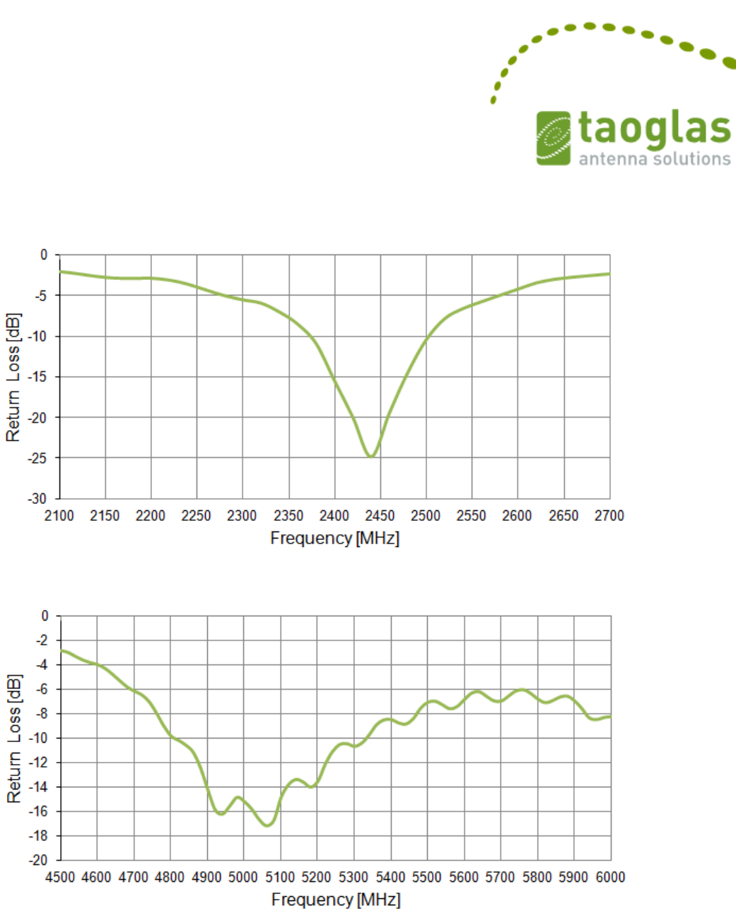
3.2 Return Loss
Figure 2. Return loss of the FXP840 antenna from 2100 MHz to 2700 MHz.
Figure 3. Return loss of the FXP840 antenna from 4500 MHz to 6000 MHz.
SPE-12-8-115/E/EZ Page 6 of 15
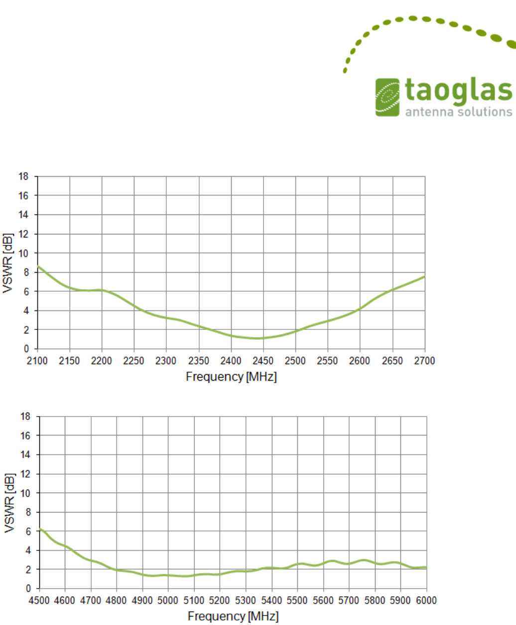
3.3 VSWR
Figure 4. VSWR of the FXP840 antenna from 2100 MHz to 2700 MHz.
Figure 5. VSWR of the FXP840 antenna from 4500 MHz to 6000 MHz
SPE-12-8-115/E/EZ Page 7 of 15
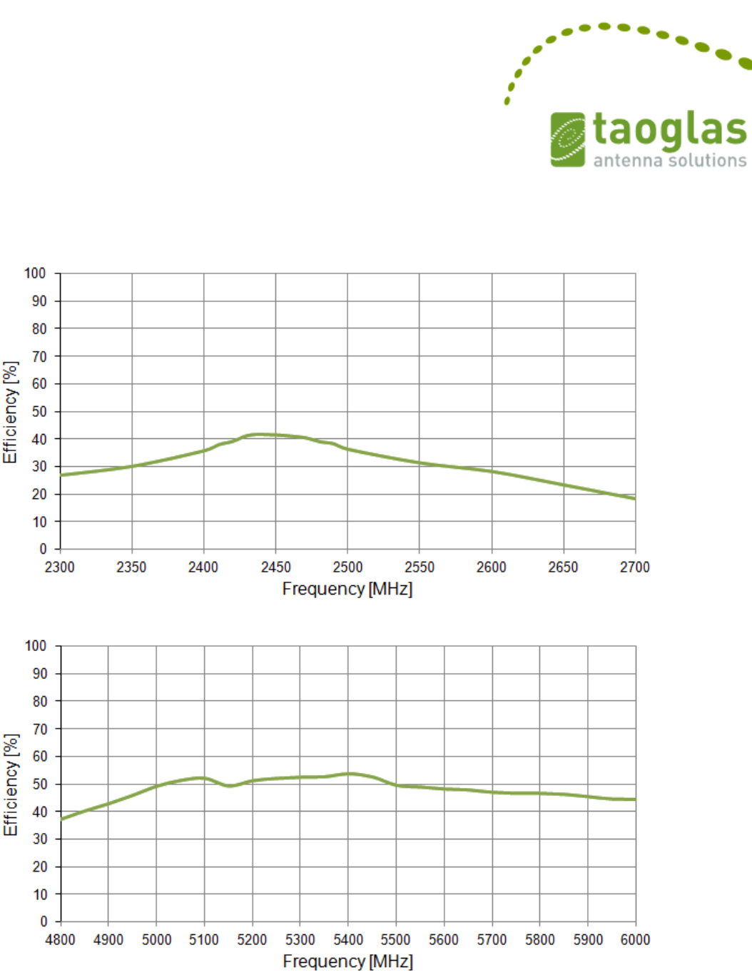
3.4 Efficiency
Figure 6. Efficiency of the FXP840 antenna from 2300 MHz to 2700 MHz.
Figure 7. Efficiency of the FXP840 antenna from 4800 MHz to 6000 MHz.
SPE-12-8-115/E/EZ Page 8 of 15
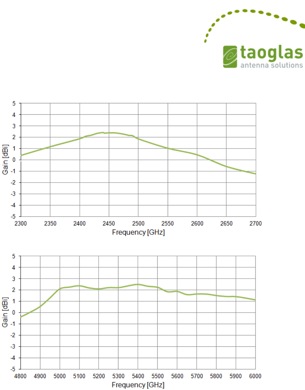
3.5 Peak Gain
Figure 8 Peak Gain of the FXP840 antenna from 2300 MHz to 2700 MHz.
Figure 9. Peak Gain of the FXP840 antenna from 4800 MHz to 6000 MHz.
SPE-12-8-115/E/EZ Page 9 of 15
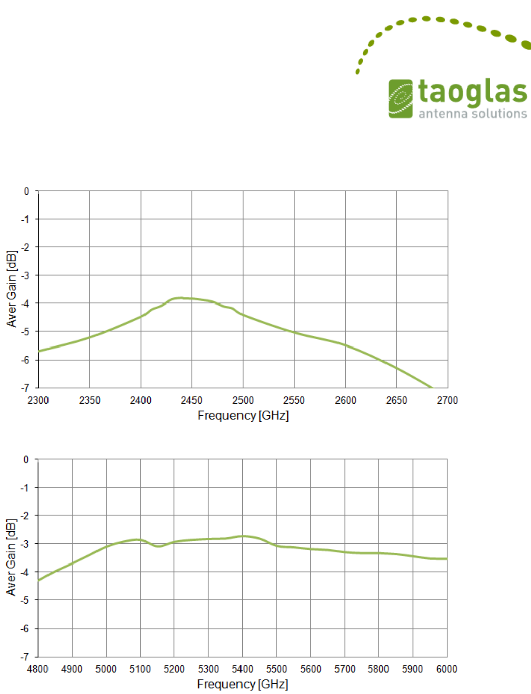
3.6 Average Gain
Figure 10. Average Gain of the FXP840 antenna from 2300 MHz to 2700 MHz.
Figure 11 Average Gain of the FXP840 antenna from 4800 MHz to 6000 MHz.
SPE-12-8-115/E/EZ Page 10 of 15
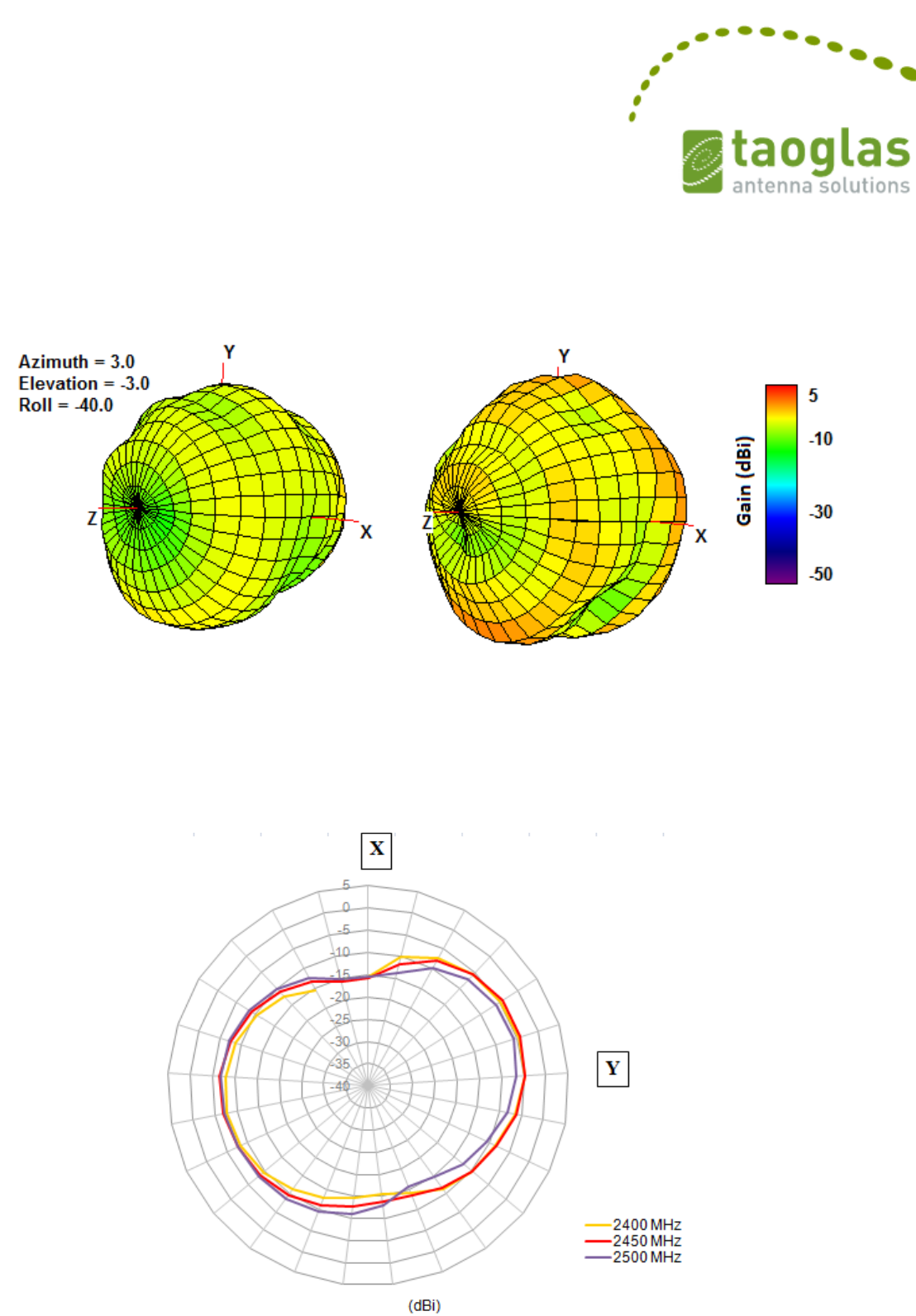
3.7 3D radiation patterns
Figure 12. 3D Radiation Pattern at 2450 MHz (left side),
Radiation Pattern at 5000 MHz (right side) of the FXP840 Antenna.
3.8 2D radiation patterns
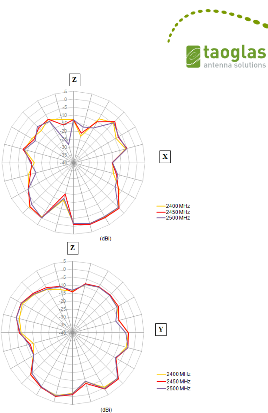
SPE-12-8-115/E/EZ Page 11 of 15
Figure 13. 2D Radiation Pattern at 2400MHz band
SPE-12-8-115/E/EZ Page 12 of 15
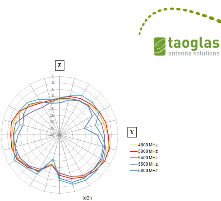
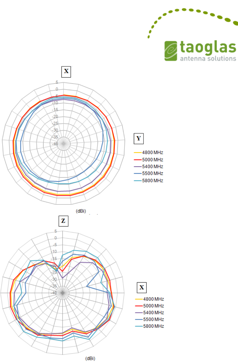
SPE-12-8-115/E/EZ Page 13 of 15
Figure 14. 2D Radiation Pattern at 5800MHz band
SPE-12-8-115/E/EZ Page 14 of 15
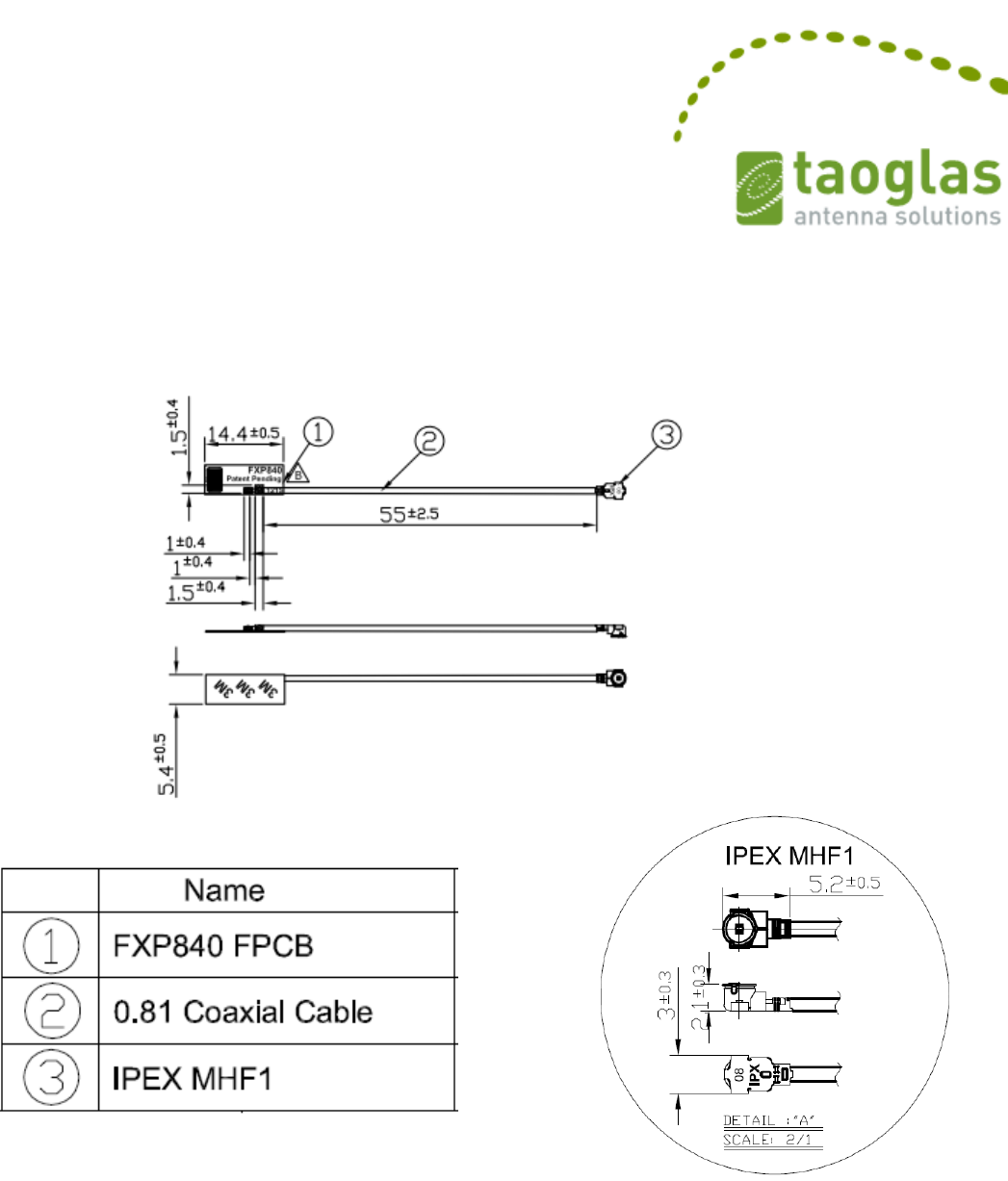
4. Antenna Drawing
Figure 15. Antenna drawing
SPE-12-8-115/E/EZ Page 15 of 15
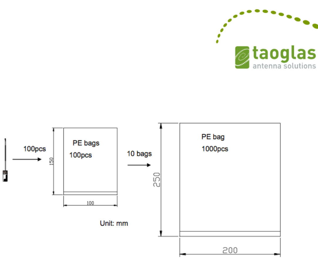
5. Packaging
Figure 16. Package of the FXP840 Antenna.
Taoglas makes no warranties based on the accuracy or completeness of the contents of this document and reserves the right to
make changes to specifications and product descriptions at any time without notice.
Taoglas reserves all rights to this document and the information contained herein. Reproduction, use or disclosure to third
parties without express permission is strictly prohibited. Copyright © 2012, Taoglas Ltd.

lS0 N0: tDl{-15-8-xxxx ( Releose )
I ^r.ou I
F-----:zl----+l
\---- -----
Detoil A
Scole:2:1
NOTES:
l.No dregs or insufficient soldering. Solder thickness 0.3 -l.7mm
2.The solder must be smooth ond full to the edges of the pod.
The solder must not extend outside of the pod oreo.
3.1he connector position hos speciol orienlotion io the PCB os
per drowing.
4.All moteriol musl be RoHS compliont.
S.Open/short QC, VSWR required.
6.Soldered orco. @
15/11 /13
1001 r2E02001 lA
'r00r 12E0200r 1A
SPECFIED
TOLERANCES ON:
.xr 0.2
xx.r 0.5 .xx+ 0.1
DATI: 201 5/1 1 /1 iS !"?.?.9. [n,?- -,, .".,,"
ft &.dry d lb liBel ddgn c(@ e t@d Iq6. k
to h @pH d q!6 to hrd Fd6 trfft tu *lfu dd d Iioda.
UNIT: mm
TH|RD AIGLE A, --l
PRo.,EcTroN V t- TIILE. : 2.4/5.lGhz Flex Micro PCB Antenno
'l55mm 0.81 lPtX MHFI(U.FL comp)
DRAWN BY:
Ho ley
CHTCKTD BY:
Dovid/Joson
APPROViD BY:
Poul PART N0. : FXP840.07,01558
I
a3
Y
- f -... ,,A,,
-l
{i

Document No. DE0095 Rev 5
Bosch Automotive Service Solutions
Print Date: 8/24/2015 Bosch Automotive Service Solutions Confidential 1 of 1
QMS electronic document is the controlled copy
Standard E-Item Initiation Form
Date:
E-Item (Bosch Part Number):
Description:
Project Number: Annual Usage:
Product Type: Moisture Level:
Item Group:
Sales Statistics Group:
Administrative Change #
Approved Mfg: MFG P/N: A/D: ROHS: T/R:
Notes:
Originator/Engineer: Component Engineer
Approved:
577310
Antenna,Dual Band, 2.4G/5.5G
308721
5000
HAA
221330
AHD
1
Taoglas
FXP.840.07.0155B
1
1
1
1
1
1
Nissan MIT and GT2 Projects
Eric Vande Zande
Kevin Gunther 9/17/15
N/A (Not Applicable)
9/17/15

DATA SHEET
WIRELESS COMPONENTS
PCB type antenna
ANTX15
0P111B24553
2.40 ~ 2.50GHZ / 5.150 ~ 5.875 GH
Z
Product Specification – April 29, 2015 V.0

www.yageo.com
Apr. 29, 2015 V0
Wireless Components
2
8
Product specification
PCB Type Antenna
FEATURES
& BENEFITS
The smallest PCB antenna in
the market
Miniature design allows users
to save required space
Double-side adhesive tape
makes it easy to instal in
device
Ranges of types of connector
and cable provide a flexible
design options
Halogen free and RoHS
compliant
APPLICATIONS
Tablet / Desktop PC
Internet TV / STB /
Game console / Camera
WiFi network devices
(IEEE 802.11b/g/n)
Bluetooth / ZigBee devices
Car Infotainment
Smart meter
Lighting control
POS terminal
Wireless Industrial Control
ORDERING INFORMATIO
N - GLOBAL PART NUMBER, PHYCOMP CTC &
12NC
All part number
s are identified by the series, packing type, material, size,
antenna
type, working frequency and packing quantity.
Y
YA
AG
GE
EO
O
B
BR
RA
AN
ND
D
o
or
rd
de
er
ri
in
ng
g
c
co
od
de
e
GLOBAL PART NUMBER (PREFERRED)
ANT
X150 P 111 B 2455 3
(1) (2) (3) (4) (5) (6) (7)
(
1) FAMILY
ANT = Antenna products
(
2) CONNECTOR & CABLE LENGTH (MM)
X = I-PEX
150 = 150mm
(
3) ANTENNA TYPE
P=PCB
(
4) SERIAL NUMBER
Serial number 111
(
5) PACKAGE TYPE
B = Bulk
(
6) WORKING FREQUENCY
2455 = 2.40 ~ 2.50 GHz / 5.150 ~ 5.875 GHz
(
7) CABLE TYPE
3 = 1.13mm diameter Mini-Coaxial Cable
www.yageo.com
Apr. 29, 2015 V0
Wireless Components
3
8
Product specification
PCB Type Antenna
SPECIFICATIONS
DESCRIPTION
VALUE
Working
Frequency
2.40 ~ 2.50 GHz / 5.150 ~ 5.875 GHz
VSWR
2.5:1max / 2.5:1 max
Peak Gain
3.2 dBi / 3.4
dBi
Polarization
Linear
Radiation Pattern
Omni-
directional
Impedance
50 Ω
Nominal
Operating Temperature
–40 °C to 85
°C
Maximum Power
1 W
PCB Dimension
40mm x 8mm x 0.5
5mm
Radio Connector
I-PEX (20278-112R-
13)
Cable Diameter / Length
/ Color 1.13mm / 150mm
/ Black
Mounting
Adhesive Tape (HF-
DS)
Ta b le 1
O
O
U
UT
TL
LI
IN
NE
ES
S
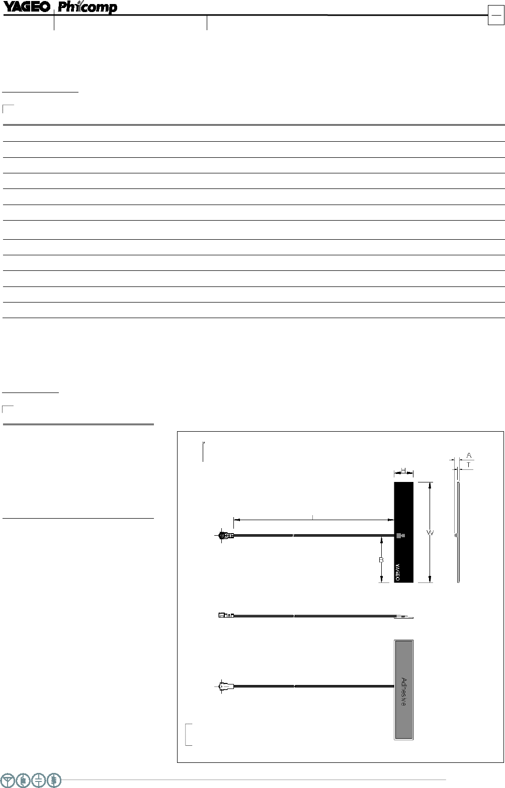
Fig. 1 Antenna outlines
DIMENSIONS
DIMENSION
VALUE
L (
mm) 150 ±
3.00
W (
mm) 40±-
0.30
H
(mm) 8±
0.30
B
(mm) 4±
1.00
T
(mm) 0.55±
0.15
A
(mm)
2.30Max
Table 2 Mechanical Dimension
www.yageo.com
Apr. 29, 2015 V0
Wireless Components
4
8
Product specification
PCB Type Antenna
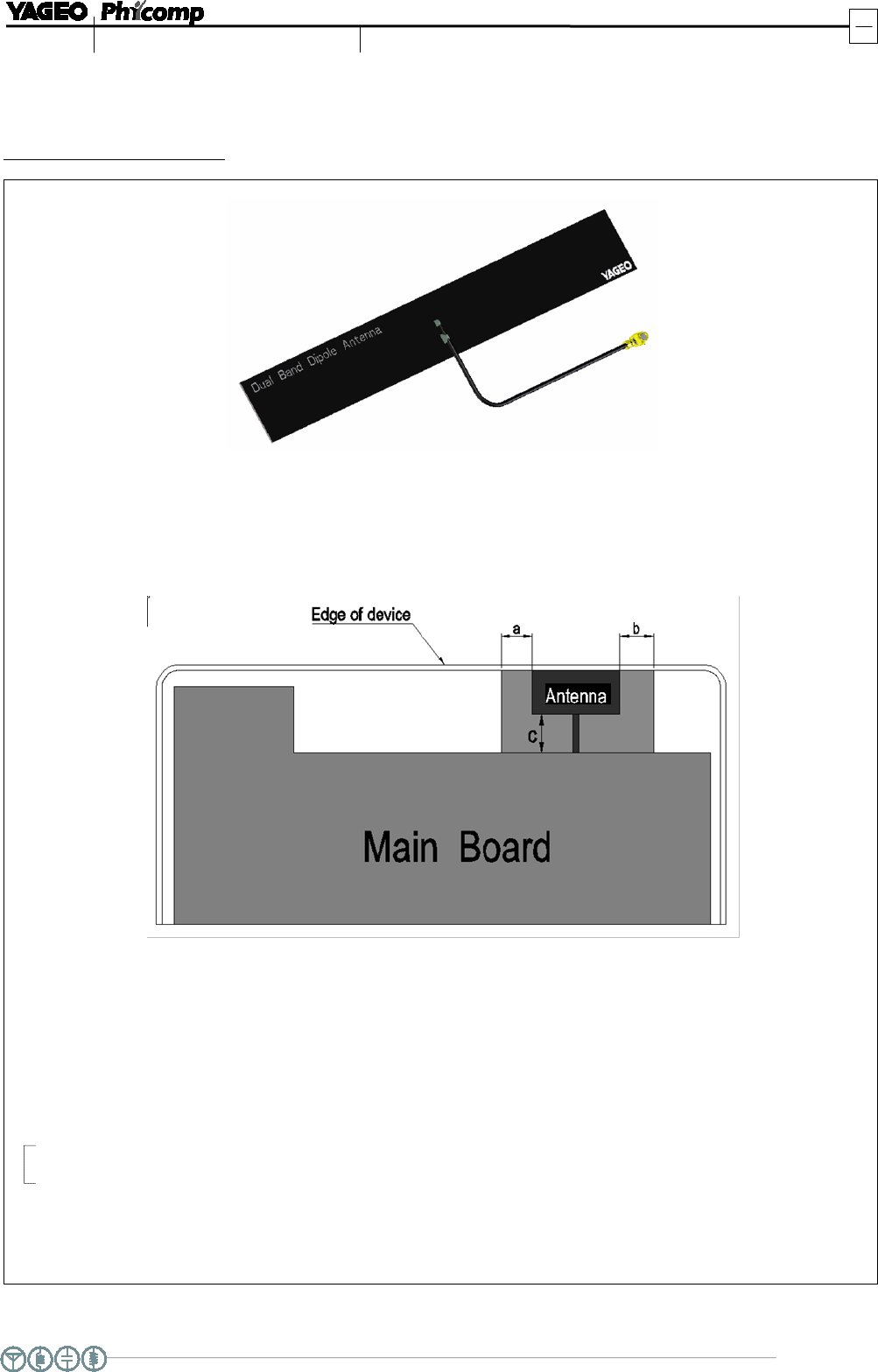
Fig. 2 Application Instruction
APPLICATION INSTRUCT
ION
Antenna element should be placed at the edge of device, has minimum clearance
from metalic object:
A: 5 mm Min
B:
5 mm Min
C: 10 mm Min
www.yageo.com
Apr. 29, 2015 V0
Wireless Components
5
8
Product specification
PCB Type Antenna
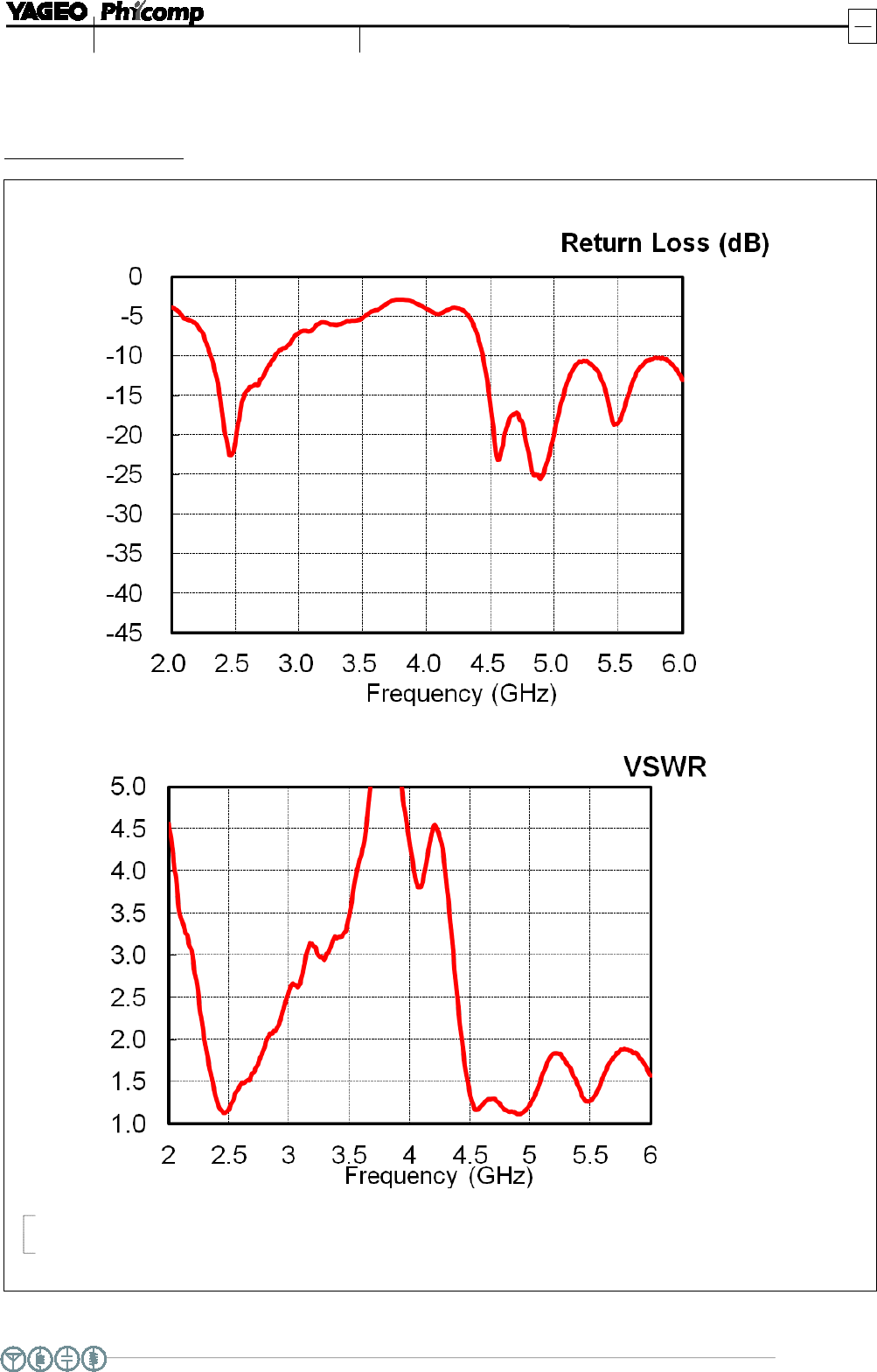
Fig. 3
Return loss & VSWR Measurement
RETURN LOSS & VSWR
www.yageo.com
Apr. 29, 2015 V0
Wireless Components
6
8
Product specification
PCB Type Antenna
Total
0
180
30
210
60
240
90 270
120
300
150
330
0
180
30
210
60
240
90 270
120
300
150
330
0
180
30
210
60
240
90 270
120
300
150
330
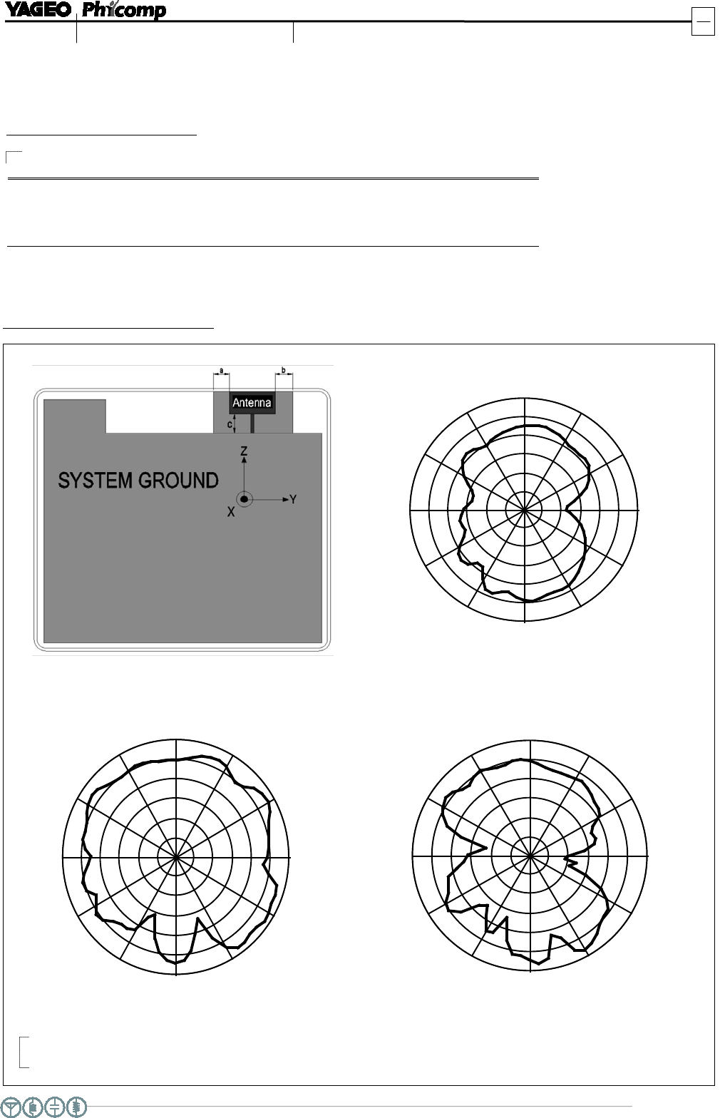
Fig. 4 Antenna radiation patterns at 2.45 GHz
Device Setup & Coordinates
ANTENNA RADIATION PA
TTERNS
ANTENNA GAIN & EFFICIENCY
FREQUENCY (GHz) AVERAGE GAIN (dBi) EFFICIENCY (%) PEAK GAIN (dBi)
2.40 -0.8 83.2 3.2
2.45 -1.1 78.4 2.9
2.50 -2.0 63.4 2.4
X-Y Plane
X-Z Plane Y-Z Plane
Ta b le 3
Scale
: 5 dBi / div Max : 5 dBi Min : -25 dBi
www.yageo.com
Apr. 29, 2015 V0
Wireless Components
7
8
Product specification
PCB Type Antenna
0
180
30
210
60
240
90 270
120
300
150
330
0
180
30
210
60
240
90 270
120
300
150
330
0
180
30
210
60
240
90 270
120
300
150
330
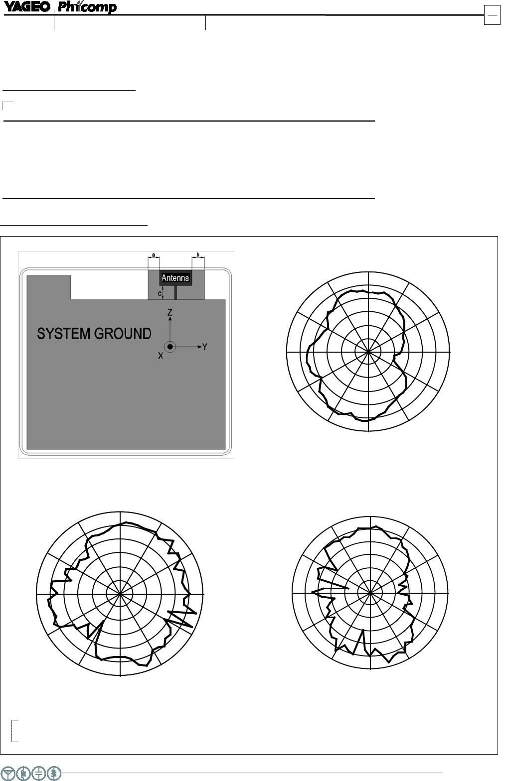
Fig. 5 Antenna radiation patterns at 5.350 GHz
Device Setup & Coordinates
ANTENNA RADIATION PA
TTERNS
ANTENNA GAIN & EFFICIENCY
FREQUENCY (GHz) AVERAGE GAIN (dBi) EFFICIENCY (%) PEAK GAIN (dBi)
5.150 -2.3 59.4 2.5
5.350 -2.4 57.9 1.6
5.475 -2.3 59.0 1.7
5.725 -2.4 58.0 3.4
5.875 -2.4 57.5 2.0
Ta b le 4
Scale
: 5 dBi / div Max : 5 dBi Min : -25 dBi
X-Y Plane
X-Z Plane Y-Z Plane

www.yageo.com
Apr. 29, 2015 V0
Wireless Components
8
8
Product specification
PCB Type Antenna
REVISION HISTORY
REVISION
DATE
CHANGE NOTIFICATION
DESCRIPTION
Version 0
Apr. 29, 2015
-
-
New data sheet for PCB type antenna,
2.40 ~ 2.50GHz / 5.150 ~ 5.875 GHz