Bosch Security Systems B123B UHF WIRELESS MICROPHONE User Manual 220d 220s
Bosch Security Systems, Inc. UHF WIRELESS MICROPHONE 220d 220s
UserManual.wiki
>
Bosch Security Systems
>
B123B User Manual
Users Manual
Navigation menu
Upload a User Manual
Namespaces
Wiki Guide
HTML
PDF
Info
Views
User Manual
Discussion / Help
Navigation
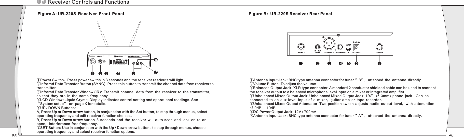
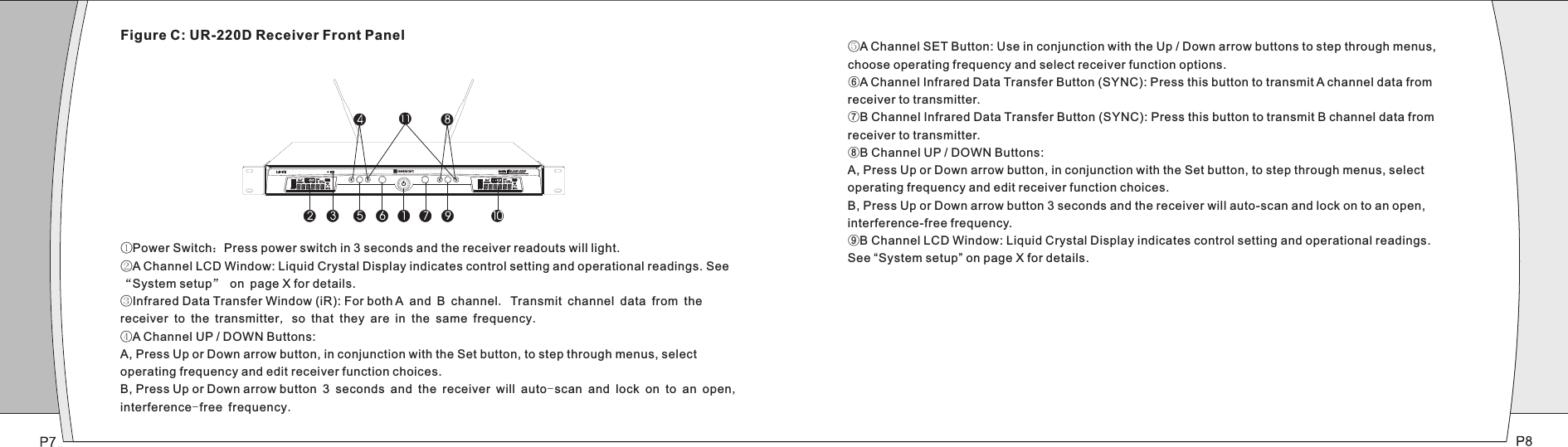
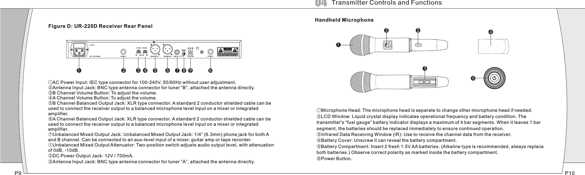
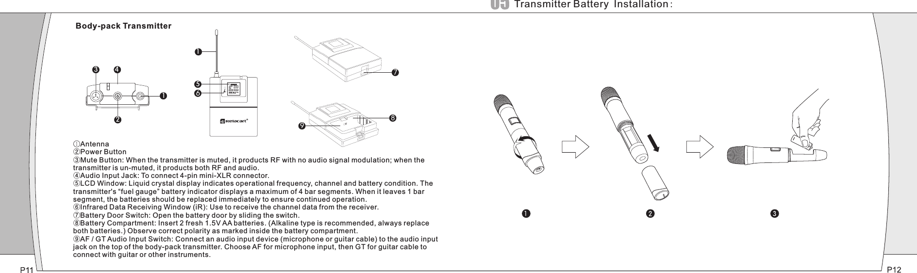
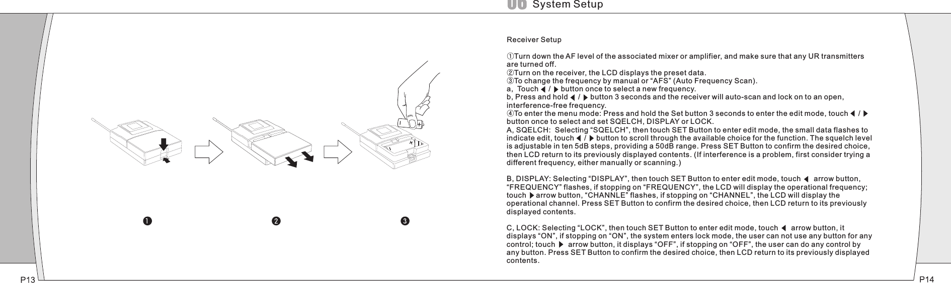
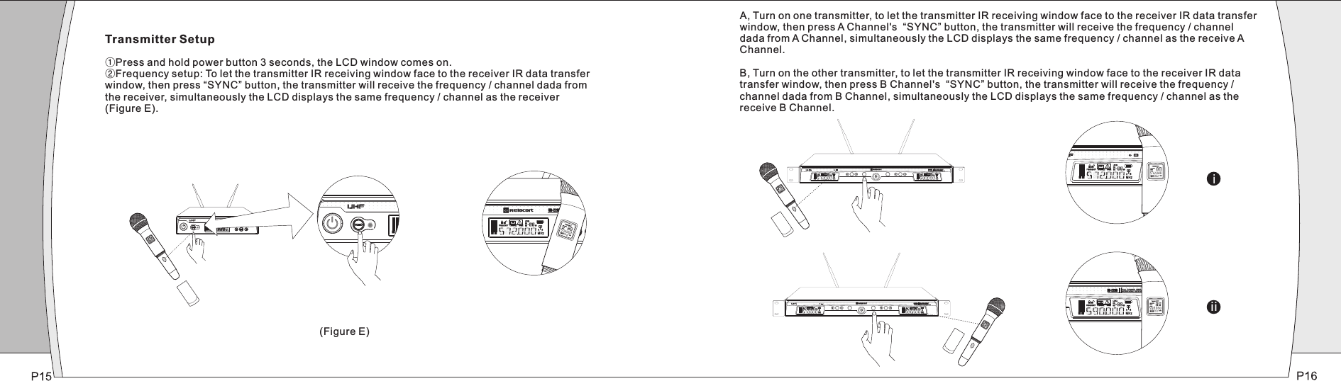
![SET SYNC SETSYNC①EIA-standard metal 1/2 - rack receiver chassis, antenna diversity.②The Handheld Transmitter offers durable, ergonomic metal bodies, soft-touch controls.③Bright and easy-to-read LCD display shows RF/AF, diversity strengths; transmitter battery level; meanwhile, can set up selective channel, frequency, mute and other working status.④Press the "AFS"(Auto Frequency Selection) button 3 S and the receiver will auto-scan and lock on to an open, interference-free frequency⑤Press [IR] button to upload automatically the receiver frequency to the transmitter.⑥PLL (Phase Lock Loop frequency control) design ensures transmission reliability, "NoiseLock" squelch effectively blocks stray RF. ⑦Each channel 32 selectable frequencies, dual- channel total 768 selectable frequencies.⑧Battery life is up to 15 hours.⑨Designed for use on professional tours, concert halls and houses of worship. Stable functions, reliable and flexible performance, easy to install.IntroductionInstallation:①For better operation the receiver should be at least 3ft. 1m above the ground and at least 3ft. away from a wall or metal surface to minimize reflections.②Attached a pair of UHF antennas to the antenna input jacks, the antenna are normally positioned in the shape of a “V” (both 45°from vertical) for best reception.③Keep antennas away from noise sources such as computer, digital equipment, motors, automobiles and neon lights, as well as away from large metal objects.④Keep open space between the receiver and transmitter for better reception.⑤The transmitter should be at least 3ft. from the receiver.Connections:①The switching power supply is designed to operate properly from any AC power source 100-240V, 50/60Hz without user adjustment. Simply connect the receiver to a standard AC power outlet, using only an IEC-type input cordset approved for the country use. Power to the unit is controlled by the front panel power switch.②There are two audio outputs on the rear panel: an XLR microphone output and a 1/4” (6.3mm) phone jack instrument output. The two isolated audio outputs permit simultaneous feeds to two different inputs. Use the appropriate shielded audio cable for connections between the receiver and the input (s) of the mixer or other equipment.3, Receiver Controls and Functions( )Receiver Installation and Connections](https://usermanual.wiki/Bosch-Security-Systems/B123B/User-Guide-1402143-Page-3.png)