Bosch Security Systems B123B UHF WIRELESS MICROPHONE User Manual 220d 220s
Bosch Security Systems, Inc. UHF WIRELESS MICROPHONE 220d 220s
Users Manual
UR-220S / 220D Series
Professional UHF Wireless Microphones
Installation and Operation

Introduction… … … … … … … … … … … … … … … … … … … … … … … … … … … … … …P3
Receiver Installation and Connections…………………………………………………………P4
·Installation… … … … … … … … … … … … … … … … … … … … … … … … … … … … … … … …P4
·Connections… … … … … … … … … … … … … … … … … … … … … … … … … … … … … … … …P4
Receiver Controls and Functions………………………………………………………………P5
UR-220S Front panel… … … … … … … … … … … … … … … … … … … … … … … … … … … … … …P5
UR-220S Rear panel… … … … … … … … … … … … … … … … … … … … … … … … … … … … … …P6
UR-220D Front panel………………………………………………………………………………P7
UR-220D Rear panel… … … … … … … … … … … … … … … … … … … … … … … … … … … … … …P9
Transmitter Controls and Functions……………………………………………………………P10
·Handheld Microphone………………………………………………………………………P10
·Bodypack Transmitter… … … … … … … … … … … … … … … … … … … … … … … … … …P11
Transmitter Battery Installation… … … … … … … … … … … … … … … … … … … … … … … …P12
System Setup… … … … … … … … … … … … … … … … … … … … … … … … … … … … … … … …P14
·Receiver Setup… … … … … … … … … … … … … … … … … … … … … … … … … … … … … …P14
·Transmitter Setup……………………………………………………………………………P15
Specifications………………………………………………………………………………………P17
……… Thank you for choosing a RELACART professional wireless microphone system. You have joined
thousands of other satisfied customers. Our years of professional experience of design and
manufacturing to ensure our products' quality, performance and reliability.
Contents
SET SYNC SET
SYNC
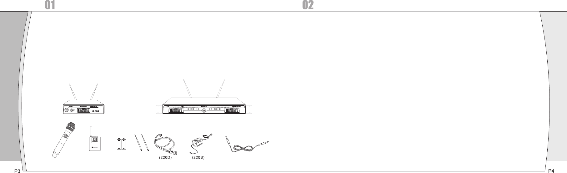
①EIA-standard metal 1/2 - rack receiver chassis, antenna diversity.
②The Handheld Transmitter offers durable, ergonomic metal bodies, soft-touch controls.
③Bright and easy-to-read LCD display shows RF/AF, diversity strengths; transmitter battery level;
meanwhile, can set up selective channel, frequency, mute and other working status.
④Press the "AFS"(Auto Frequency Selection) button 3 S and the receiver will auto-scan and lock
on to an open, interference-free frequency
⑤Press [IR] button to upload automatically the receiver frequency to the transmitter.
⑥PLL (Phase Lock Loop frequency control) design ensures transmission reliability, "NoiseLock"
squelch effectively blocks stray RF.
⑦Each channel 32 selectable frequencies, dual- channel total 768 selectable frequencies.
⑧Battery life is up to 15 hours.
⑨Designed for use on professional tours, concert halls and houses of worship. Stable functions,
reliable and flexible performance, easy to install.
Introduction
Installation:
①For better operation the receiver should be at least 3ft. 1m above the ground and at least 3ft.
away from a wall or metal surface to minimize reflections.
②Attached a pair of UHF antennas to the antenna input jacks, the antenna are normally positioned in the
shape of a “V” (both 45°from vertical) for best reception.
③Keep antennas away from noise sources such as computer, digital equipment, motors, automobiles
and neon lights, as well as away from large metal objects.
④Keep open space between the receiver and transmitter for better reception.
⑤The transmitter should be at least 3ft. from the receiver.
Connections:
①The switching power supply is designed to operate properly from any AC power source 100-240V,
50/60Hz without user adjustment. Simply connect the receiver to a standard AC power outlet, using only
an IEC-type input cordset approved for the country use. Power to the unit is controlled by the front panel
power switch.
②There are two audio outputs on the rear panel: an XLR microphone output and a 1/4” (6.3mm) phone
jack instrument output. The two isolated audio outputs permit simultaneous feeds to two different
inputs. Use the appropriate shielded audio cable for connections between the receiver and the
input (s) of the mixer or other equipment.
3, Receiver Controls and Functions
( )
Receiver Installation and Connections
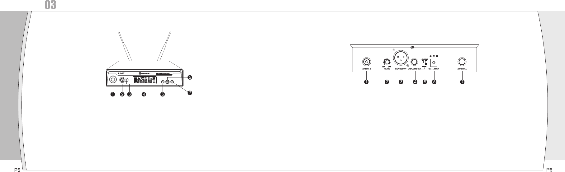
Figure A: UR-220S Receiver Front Panel
①Power Switch:Press power switch in 3 seconds and the receiver readouts will light.
②Infrared Data Transfer Button (SYNC): Press this button to transmit the channel data from receiver to
transmitter.
③Infrared Data Transfer Window (iR): Transmit channel data from the receiver to the transmitter,
so that they are in the same frequency.
④LCD Window: Liquid Crystal Display indicates control setting and operational readings. See
“System setup” on page X for details.
⑤UP / DOWN Buttons:
A, Press Up or Down arrow button, in conjunction with the Set button, to step through menus, select
operating frequency and edit receiver function choices.
B, Press Up or Down arrow button 3 seconds and the receiver will auto-scan and lock on to an
open, interference-free frequency.
②SET Button: Use in conjunction with the Up / Down arrow buttons to step through menus, choose
operating frequency and select receiver function options.
Receiver Controls and Functions
Figure B: UR-220S Receiver Rear Panel
①Antenna Input Jack: BNC type antenna connector for tuner ”B”, attached the antenna directly.
②Volume Button: To adjust the volume.
③Balanced Output Jack: XLR type connector. A standard 2 conductor shielded cable can be used to connect
the receiver output to a balanced microphone level input on a mixer or integrated amplifier.
④Unbalanced Mixed Output Jack: Unbalanced Mixed Output Jack: 1/4” (6.3mm) phone jack. Can be
connected to an aux-level input of a mixer, guitar amp or tape recorder.
⑤Unbalanced Mixed Output Attenuator: Two-position switch adjusts audio output level, with attenuation
of 0dB, -10dB.
⑥DC Power Output Jack: 12V / 700mA.
⑦Antenna Input Jack: BNC type antenna connector for tuner ”A”, attached the antenna directly.
SET SYNC SET
SYNC
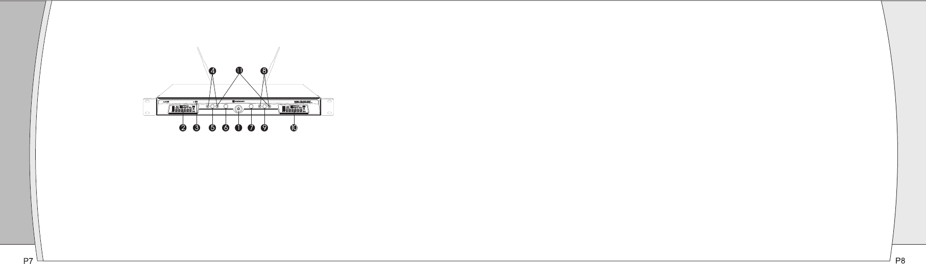
①Power Switch:Press power switch in 3 seconds and the receiver readouts will light.
②A Channel LCD Window: Liquid Crystal Display indicates control setting and operational readings. See
“System setup” on page X for details.
③Infrared Data Transfer Window (iR): For both A and B channel. Transmit channel data from the
receiver to the transmitter, so that they are in the same frequency.
④A Channel UP / DOWN Buttons:
A, Press Up or Down arrow button, in conjunction with the Set button, to step through menus, select
operating frequency and edit receiver function choices.
B, Press Up or Down arrow button 3 seconds and the receiver will auto-scan and lock on to an open,
interference-free frequency.
Figure C: UR-220D Receiver Front Panel ⑤A Channel SET Button: Use in conjunction with the Up / Down arrow buttons to step through menus,
choose operating frequency and select receiver function options.
⑥A Channel Infrared Data Transfer Button (SYNC): Press this button to transmit A channel data from
receiver to transmitter.
⑦B Channel Infrared Data Transfer Button (SYNC): Press this button to transmit B channel data from
receiver to transmitter.
⑧B Channel UP / DOWN Buttons:
A, Press Up or Down arrow button, in conjunction with the Set button, to step through menus, select
operating frequency and edit receiver function choices.
B, Press Up or Down arrow button 3 seconds and the receiver will auto-scan and lock on to an open,
interference-free frequency.
⑨B Channel LCD Window: Liquid Crystal Display indicates control setting and operational readings.
See “System setup” on page X for details.
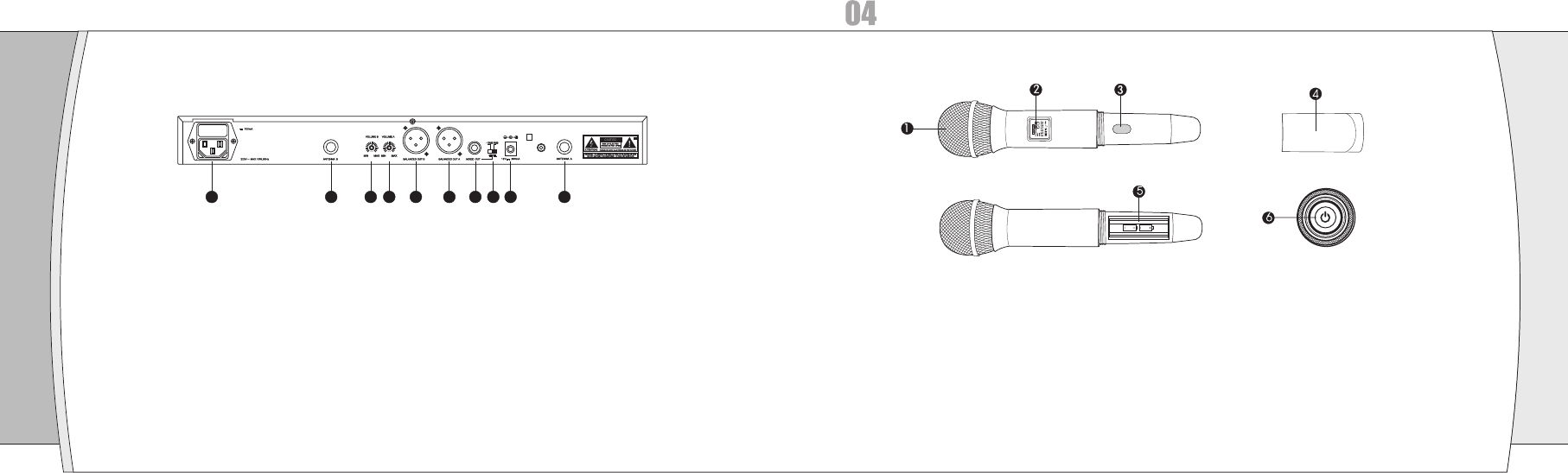
Figure D: UR-220D Receiver Rear Panel
①AC Power Input: IEC type connector for 100-240V, 50/60Hz without user adjustment.
②Antenna Input Jack: BNC type antenna connector for tuner ”B”, attached the antenna directly.
③B Channel Volume Button: To adjust the volume.
④A Channel Volume Button: To adjust the volume.
⑤B Channel Balanced Output Jack: XLR type connector. A standard 2 conductor shielded cable can be
used to connect the receiver output to a balanced microphone level input on a mixer or integrated
amplifier.
⑥A Channel Balanced Output Jack: XLR type connector. A standard 2 conductor shielded cable can be
used to connect the receiver output to a balanced microphone level input on a mixer or integrated
amplifier.
⑦Unbalanced Mixed Output Jack: Unbalanced Mixed Output Jack: 1/4” (6.3mm) phone jack for both A
and B channel. Can be connected to an aux-level input of a mixer, guitar amp or tape recorder.
①Unbalanced Mixed Output Attenuator: Two-position switch adjusts audio output level, with attenuation
of 0dB, -10dB.
②DC Power Output Jack: 12V / 700mA.
③Antenna Input Jack: BNC type antenna connector for tuner ”A”, attached the antenna directly.
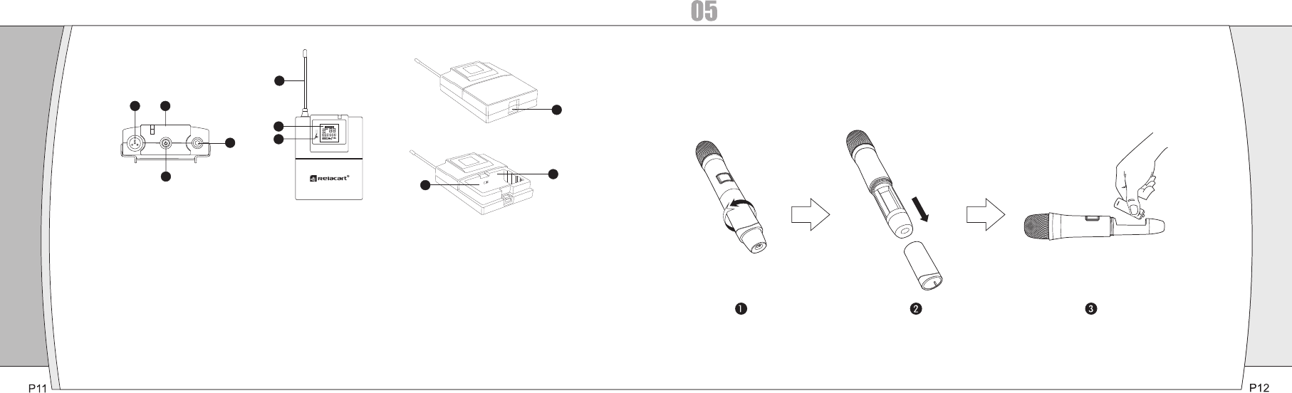
①Microphone Head: The microphone head is separate to change other microphone head if needed.
②LCD Window: Liquid crystal display indicates operational frequency and battery condition. The
transmitter's “fuel gauge” battery indicator displays a maximum of 4 bar segments. When it leaves 1 bar
segment, the batteries should be replaced immediately to ensure continued operation.
③Infrared Data Receiving Window (iR): Use to receive the channel data from the receiver.
④Battery Cover: Unscrew it can reveal the battery compartment.
⑤Battery Compartment: Insert 2 fresh 1.5V AA batteries. (Alkaline type is recommended, always replace
both batteries.) Observe correct polarity as marked inside the battery compartment.
⑥Power Button.
Transmitter Controls and Functions
Handheld Microphone
12 3 4 5 6 7 8 9 10
P9 P10
5
1
6
1
2
3 4 7
8
9
①Antenna
②Power Button
③Mute Button: When the transmitter is muted, it products RF with no audio signal modulation; when the
transmitter is un-muted, it products both RF and audio.
④Audio Input Jack: To connect 4-pin mini-XLR connector.
⑤LCD Window: Liquid crystal display indicates operational frequency, channel and battery condition. The
transmitter's “fuel gauge” battery indicator displays a maximum of 4 bar segments. When it leaves 1 bar
segment, the batteries should be replaced immediately to ensure continued operation.
⑥Infrared Data Receiving Window (iR): Use to receive the channel data from the receiver.
⑦Battery Door Switch: Open the battery door by sliding the switch.
⑧Battery Compartment: Insert 2 fresh 1.5V AA batteries. (Alkaline type is recommended, always replace
both batteries.) Observe correct polarity as marked inside the battery compartment.
⑨AF / GT Audio Input Switch: Connect an audio input device (microphone or guitar cable) to the audio input
jack on the top of the body-pack transmitter. Choose AF for microphone input, then GT for guitar cable to
connect with guitar or other instruments.
Body-pack Transmitter
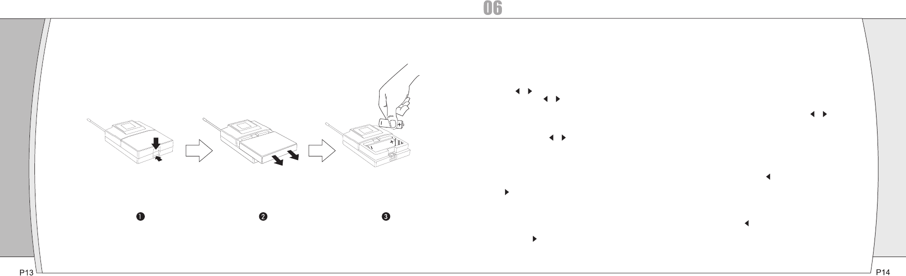
Transmitter Battery Installation:
Receiver Setup
①Turn down the AF level of the associated mixer or amplifier, and make sure that any UR transmitters
are turned off.
②Turn on the receiver, the LCD displays the preset data.
③To change the frequency by manual or “AFS” (Auto Frequency Scan).
a, Touch / button once to select a new frequency.
b, Press and hold / button 3 seconds and the receiver will auto-scan and lock on to an open,
interference-free frequency.
④To enter the menu mode: Press and hold the Set button 3 seconds to enter the edit mode, touch /
button once to select and set SQELCH, DISPLAY or LOCK.
A, SQELCH: Selecting “SQELCH”, then touch SET Button to enter edit mode, the small data flashes to
indicate edit, touch / button to scroll through the available choice for the function. The squelch level
is adjustable in ten 5dB steps, providing a 50dB range. Press SET Button to confirm the desired choice,
then LCD return to its previously displayed contents. (If interference is a problem, first consider trying a
different frequency, either manually or scanning.)
B, DISPLAY: Selecting “DISPLAY”, then touch SET Button to enter edit mode, touch arrow button,
“FREQUENCY” flashes, if stopping on “FREQUENCY”, the LCD will display the operational frequency;
touch arrow button, “CHANNLE” flashes, if stopping on “CHANNEL”, the LCD will display the
operational channel. Press SET Button to confirm the desired choice, then LCD return to its previously
displayed contents.
C, LOCK: Selecting “LOCK”, then touch SET Button to enter edit mode, touch arrow button, it
displays “ON”, if stopping on “ON”, the system enters lock mode, the user can not use any button for any
control; touch arrow button, it displays “OFF”, if stopping on “OFF”, the user can do any control by
any button. Press SET Button to confirm the desired choice, then LCD return to its previously displayed
contents.
System Setup
Transmitter Setup
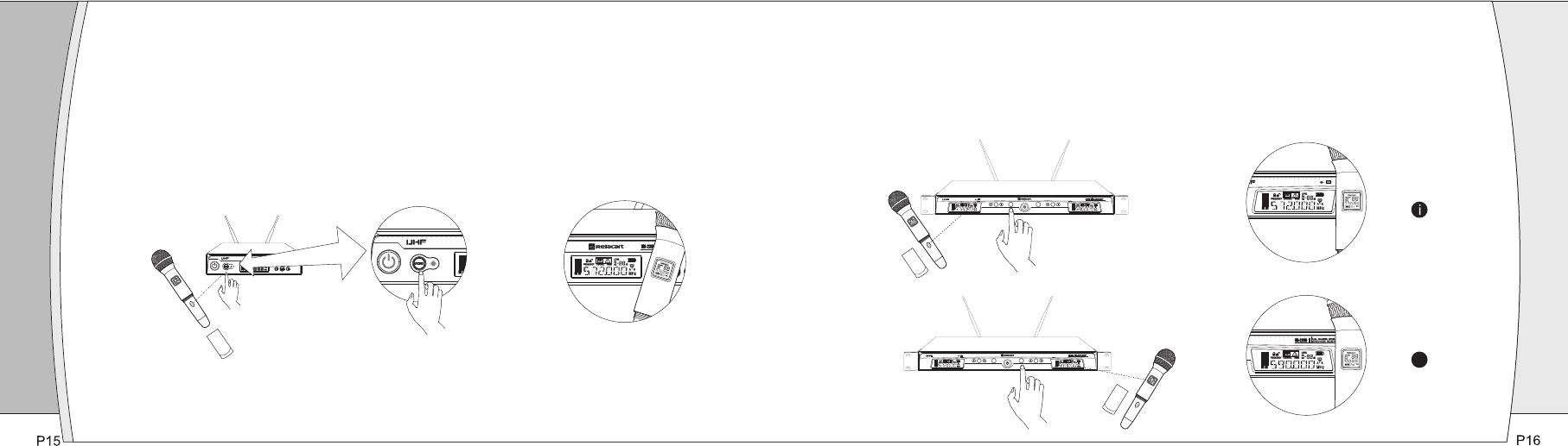
①Press and hold power button 3 seconds, the LCD window comes on.
②Frequency setup: To let the transmitter IR receiving window face to the receiver IR data transfer
window, then press “SYNC” button, the transmitter will receive the frequency / channel dada from
the receiver, simultaneously the LCD displays the same frequency / channel as the receiver
(Figure E).
SET SYNC SET
SYNC
SET SYNC SET
SYNC
ii
A, Turn on one transmitter, to let the transmitter IR receiving window face to the receiver IR data transfer
window, then press A Channel's “SYNC” button, the transmitter will receive the frequency / channel
dada from A Channel, simultaneously the LCD displays the same frequency / channel as the receive A
Channel.
B, Turn on the other transmitter, to let the transmitter IR receiving window face to the receiver IR data
transfer window, then press B Channel's “SYNC” button, the transmitter will receive the frequency /
channel dada from B Channel, simultaneously the LCD displays the same frequency / channel as the
receive B Channel.
(Figure E)

Specifications
UR-220S / UR-220D Receiver
Main Frame Size: EIA STANDARD 1/2 U (UR-220S) / EIA STANDARD 1U (UR-220D)
Channels: Single Channel (UR-220S) / Dual Channel (UR-220D)
Frequency Stability: ±0.005%, Phase Lock Loop frequency control
Carrier Frequency Range: UHF 618-936 MHz
Digital Equalizer: Preset Microphone Capsule Modeling
Modulation Mode: FM
Operating Range: 60M typical ( in open space)
Oscillation: PLL synthesized
Sensitivity: 5dBμV, S/N>60dB at 25 deviation
Band Width: 16MHz (UR-220S); 32MHz (UR-220D)
Max.Deviation Range: ±45KHz
S/N: >105dB
T.H.D.: <0.4%@1KHz
Frequency response: 80Hz~18KHz±3dB
Power Supply: DC 12V / 1A (UR-220S) / 100-240V AC50/60 Hz, 10W(UR-220D)
Weight: 1.9KG (UR-220S); 4KG (UR-220D)
Dimension: 210(W)X 43(H) X 206(D) – UR-220S / 421(W) X 43(H) X 206(D) – UR-220D
Output Connector: XLR balanced & 6.3 φphone jack unbalanced
Carrier Frequency Range UHF 618-936 MHZ
Oscillation: PLL synthesized
Harmonic radiation: <-65dBm
Bandwidth: 32MHz
Max.Deviation Range: ±45KHz
Microphone Element: Cardioid Dynamic / Cardioid Condenser
RF Power Output: 8mW
Battery: AA X 2
Current Consumption: 90mA, typical
Battery Current / Life: Approximately 15 hours
Dimension: 52(Φ) X 252 (L)
Weight: 208g ( w/o battery)
:
Carrier Frequency Range UHF 618-936 MHZ
Oscillation: PLL synthesized
Harmonic radiation: <-65 dBm
Bandwidth: 32MHz
Max.Deviation Range: ±45KHz
Input Connector: 4-pin mini-XLR connector
RF Power Output: 90mW
Battery: AA X 2
Current Consumption: 90mA, typical
Battery Current / Life: Approximately 15 hours
Dimension: 84(H) X 66(W) X 23(D)
Weight: 165g ( w/o battery)
:
UH-200 Handheld Microphone
UT-200 Body-pack Transmitter
P17 P18
07
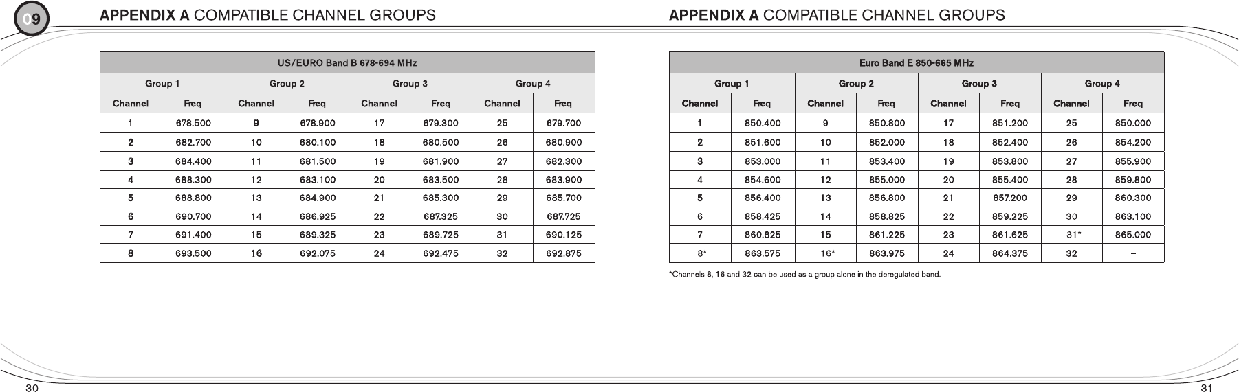
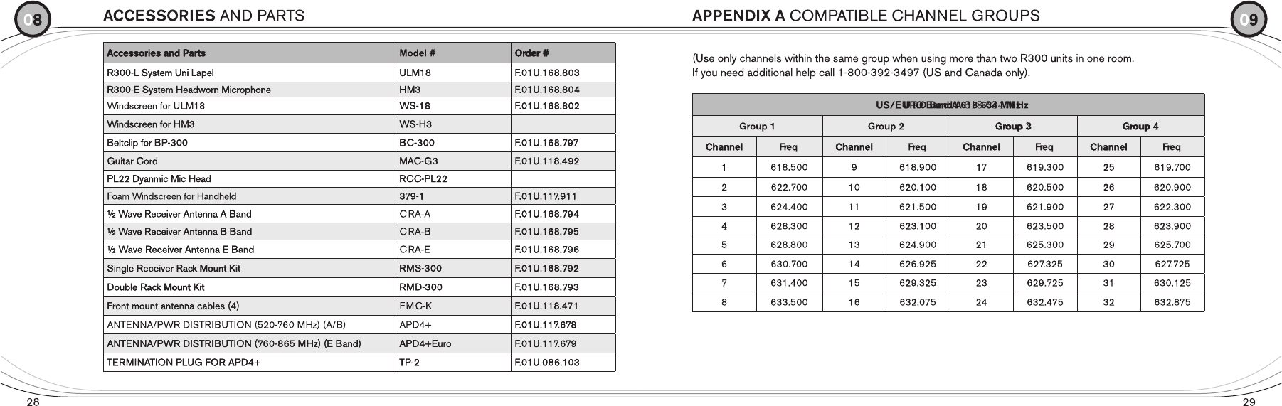

USA acceptable band ( FCC compliance ): 618.500 MHz – 633.500 MHz
Canada acceptable band ( IC compliance ): 678.500 MHz – 693.500 MHz
Europe acceptable band ( CE compliance): 850.000 MHz – 865.000 MHz
FCC NOTE:
This device complies with Part 15 of the FCC Rules. Operation is subject to the following two
conditions:(1)this device may not cause harmful interference, and (2) this device must accept
any interference received, including interference that may cause undesired operation.
The manufacturer is not responsible for any radio or TV interference caused by unauthorized
modifications to this equipment. Such modifications could void the user's authority to operate the
equipment.
IC NOTE
Operation is subject to the following two conditions:
(1)this device may not cause harmful interference, and (2) this device must accept any
interference, including interference that may cause undesired operation of the device.