Bosch Security Systems BRL1-WY WLSN RELAY MODULE User Manual USERS MANUAL
Bosch Security Systems, Inc. WLSN RELAY MODULE USERS MANUAL
UserManual.wiki
>
Bosch Security Systems
>
BRL1 WY User Manual
USERS MANUAL
Navigation menu
Upload a User Manual
Namespaces
Wiki Guide
HTML
PDF
Info
Views
User Manual
Discussion / Help
Navigation

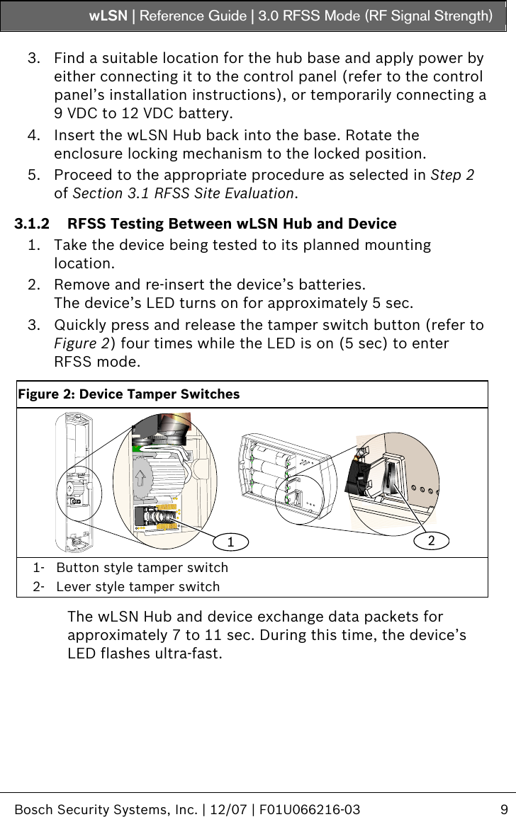
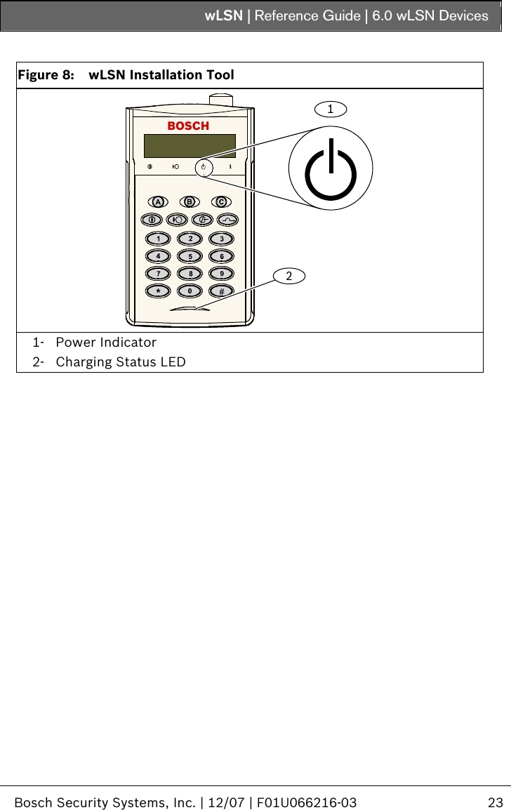
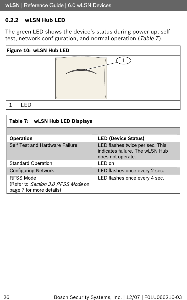
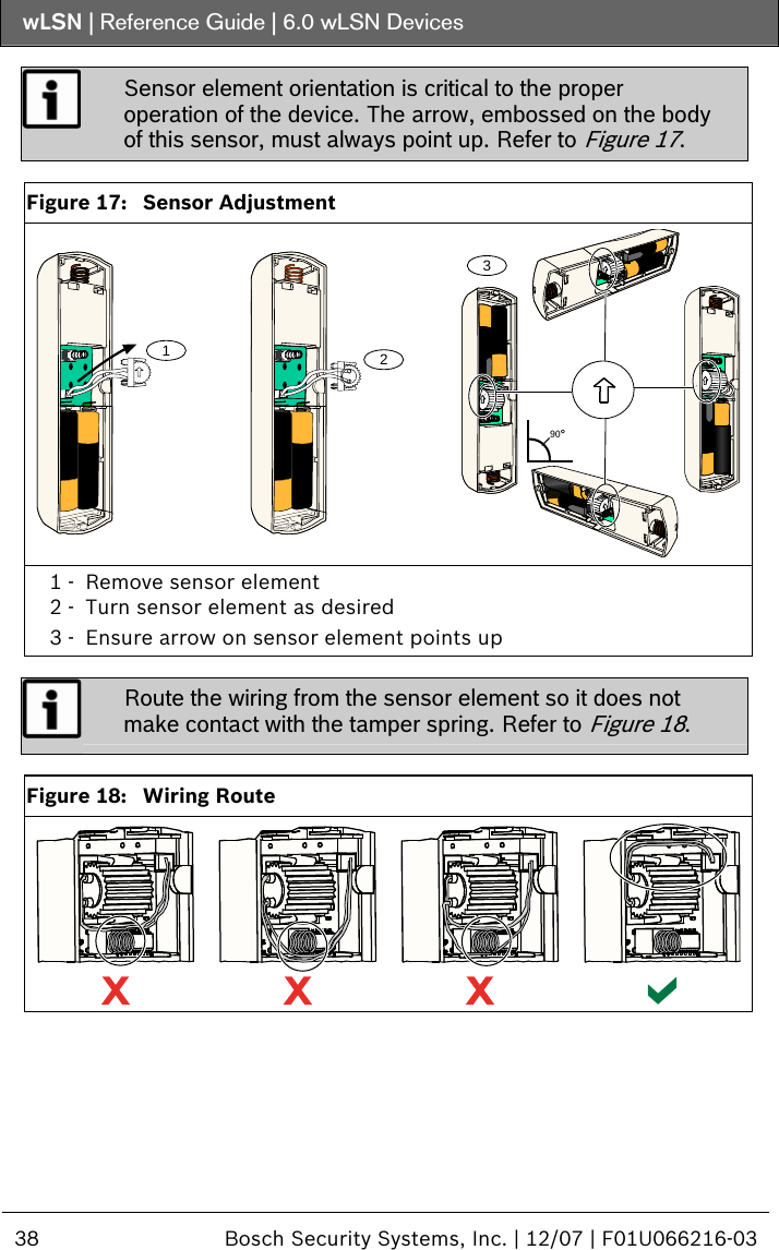
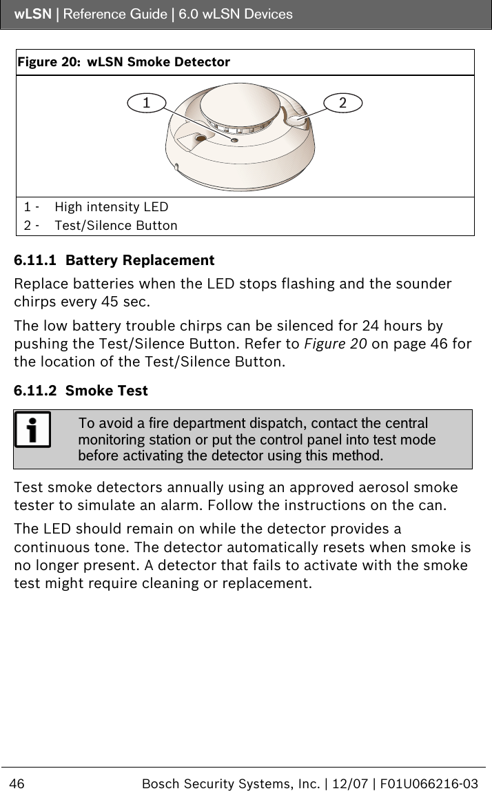
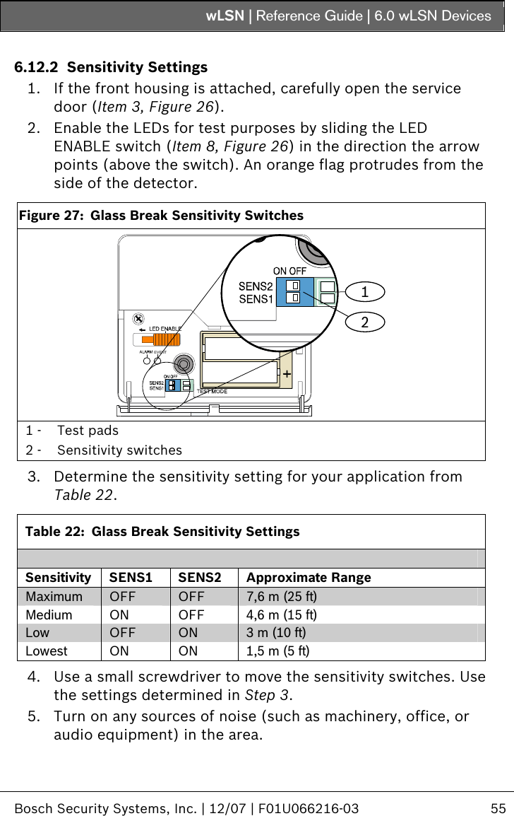
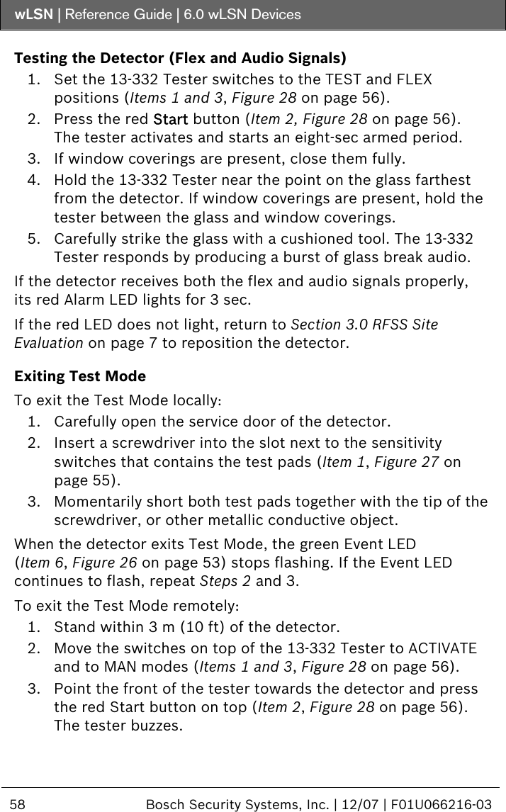
![wLSN | Reference Guide | 3.0 RFSS Mode (RF Signal Strength) Bosch Security Systems, Inc. | 12/07 | F01U066216-03 11 4. To start a new RFSS session, press and release the device’s tamper switch once. To force a device out of RFSS Mode, press and hold the device’s tamper switch for 5 sec, or remove and reinsert the device’s batteries. 5. Repeat this procedure for each device you are testing. When you finish testing the devices, return the wLSN Hub’s switches to their original position. 3.1.3 RFSS Testing Between wLSN Hub and Installation Tool The LCD Display is 2 lines by 16 characters. The LCD display flashes and beeps the sounder every 4 sec with each information update. 1. Take the Installation Tool to the device’s planned mounting location. 2. Press any key on the Installation Tool to awaken it. w L S N 9 0 0 I N S T A L L T O O L 3. Press and hold the [*] and [#] key together to enter RFSS mode. The LCD display shows: R F T E S T M O D E M O D E 1 O R 2 ? To select a mode, press its numerical key, for example, press [2] for Mode 2. 4. Hold the Installation Tool at the device’s planned mounting location. Use Mode 1 to determine if the signal strength is acceptable or not. Mode 2 helps you determine how acceptable the signal strength is.](https://usermanual.wiki/Bosch-Security-Systems/BRL1-WY/User-Guide-877582-Page-11.png)
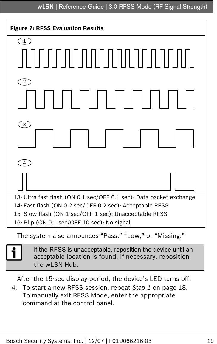
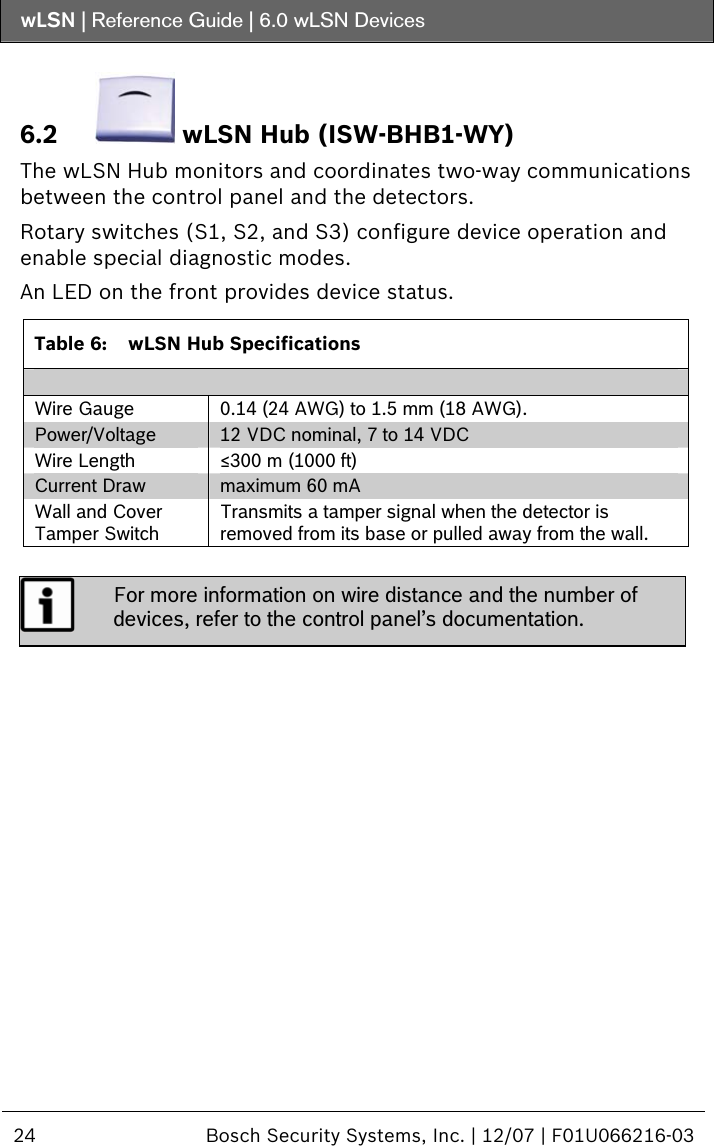
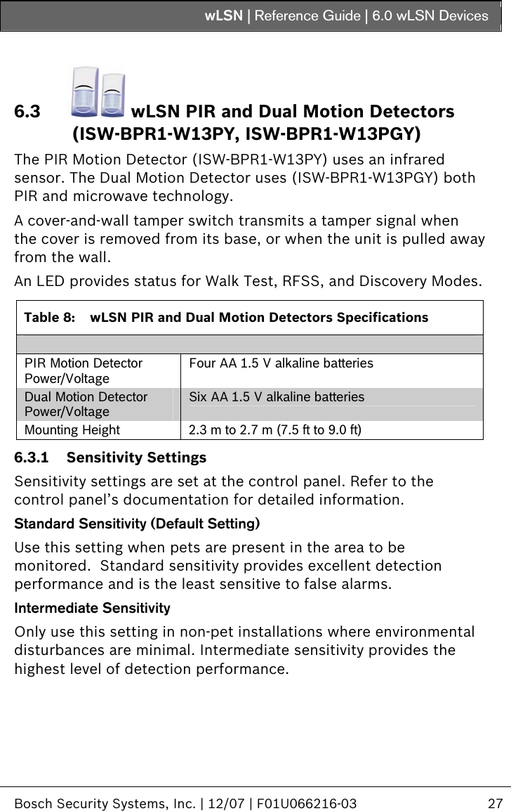
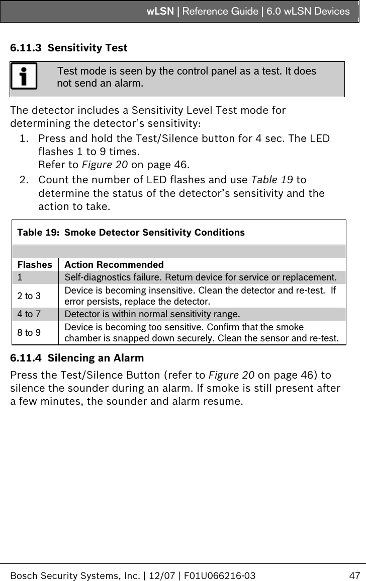
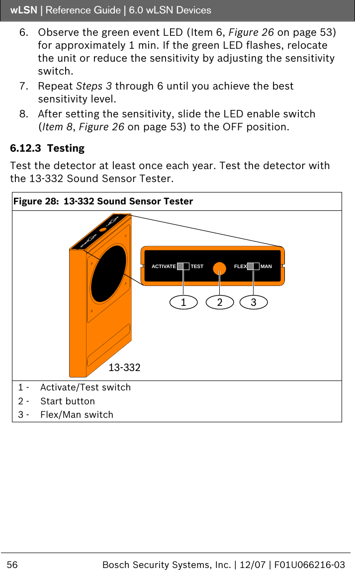
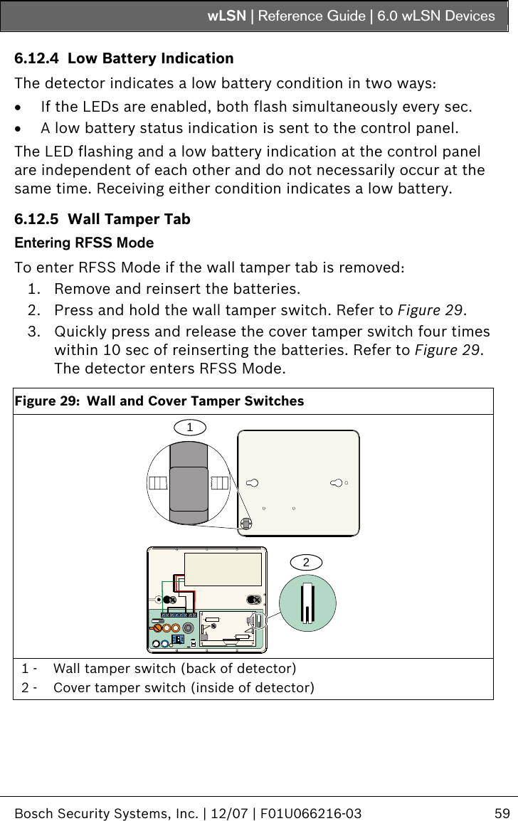
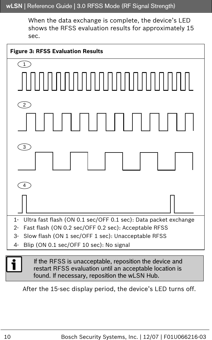
![wLSN | Reference Guide | 3.0 RFSS Mode (RF Signal Strength) 12 Bosch Security Systems, Inc. | 12/07 | F01U066216-03 Refer to Mode 1 and Mode 2 (page 12) for more information on acceptable signal strength levels. If the RFSS is unacceptable, reposition either the wLSN Hub or the Installation Tool until an acceptable location is found. 5. Repeat this procedure for each device’s location you are testing. When you finish testing locations, return the wLSN Hub’s switches to their original position. Mode 1 Select Mode 1 by pressing [1]. If the RFSS is acceptable the LCD shows: M O D E 1 : + + + OK + + + If the RFSS is unacceptable the LCD shows: M O D E 1 : - N O T O K - Mode 2 To select Mode 2: 1. Press [2]. The LCD shows: M O D E 2 : P R E S S 0 T O T RI G G E R 2. Press [0]. The Installation Tool collects data for 5 sec. The LCD shows: M O D E 2 : P S R - - - R S S : - - - - - After 5 sec, the Installation Tool beeps and shows the RFSS evaluation results for 15 sec: M O D E 2 : P S R 9 0 % R S S : J J J F F](https://usermanual.wiki/Bosch-Security-Systems/BRL1-WY/User-Guide-877582-Page-12.png)
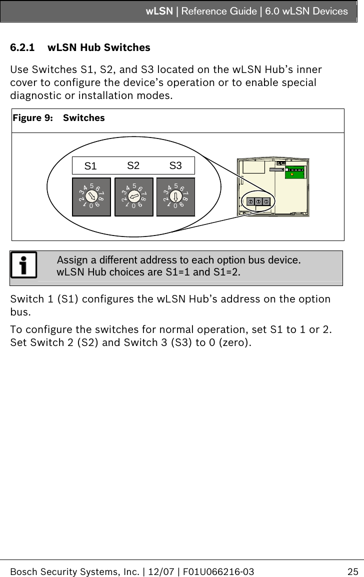
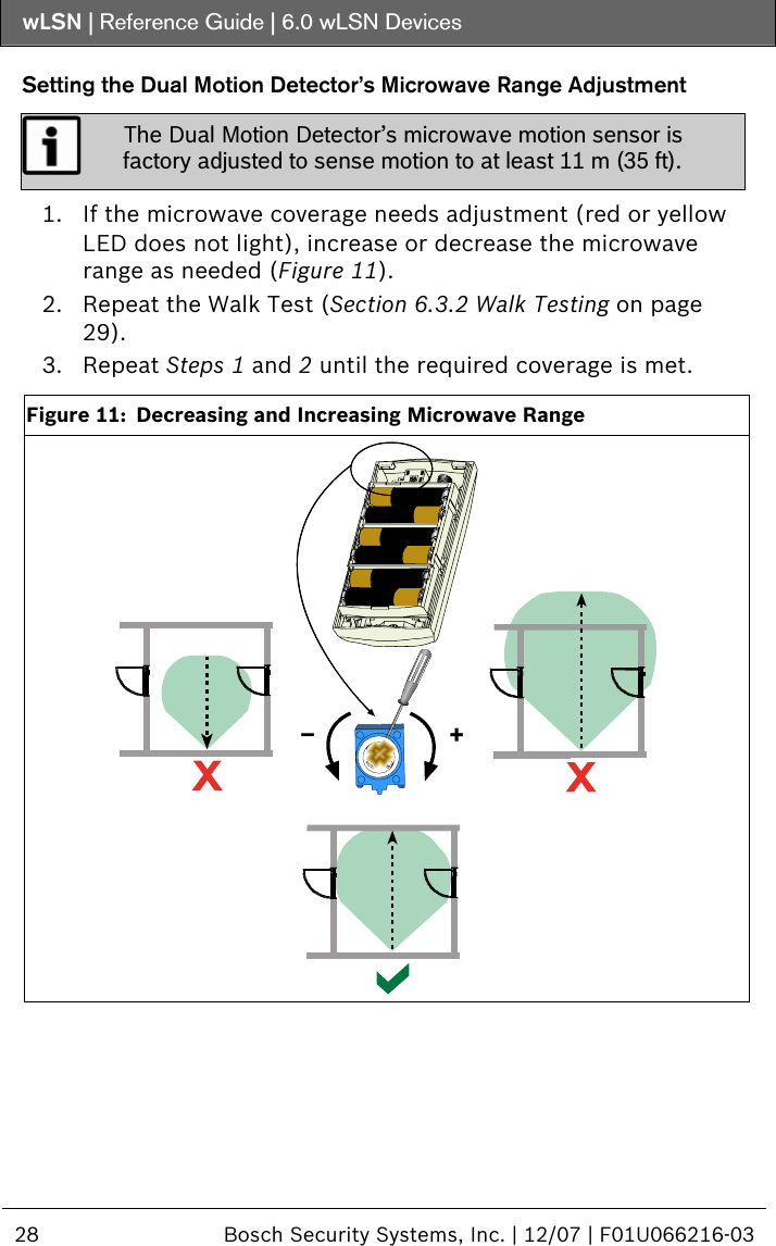
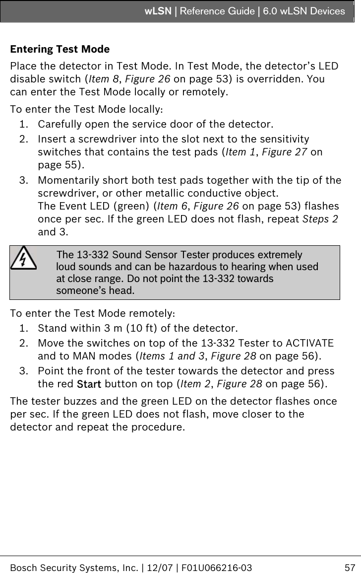
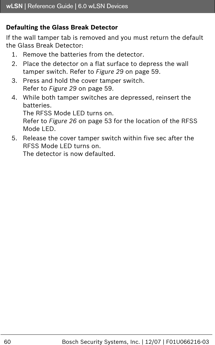
![wLSN | Reference Guide | 3.0 RFSS Mode (RF Signal Strength) Bosch Security Systems, Inc. | 12/07 | F01U066216-03 13 Mode 2 provides two indicators of signal strength: Packet Success Ratio (PSR) and Received Signal Strength (RSS). PSR is the ratio of successfully received packets to sent packets. The Installation Tool shows PSR as a percentage. For example, if the wLSN Hub sends 10 packets and the Installation Tool receives 9 packets, the PSR is 90%. RSS indicates the power level of the received messages. The Installation Tool shows RSS using power bars. The maximum number of bars is five. The best location for placing the device is the one that shows the highest PSR percentage and the highest number of power bars. A PSR of 100% and five RSS power bars indicates the strongest signal, which identifies the best location. Table 3: Interpreting Mode 2 Display Power Bars PSR Evaluation 50% - 59% Unacceptable 50% - 59% Marginal (not recommended) 60% - 69% Acceptable 70% - 79% Good 80% - 89% Very good 90% - 99% Excellent When the 15-sec display period ends, the LCD shows: M O D E 2 : P R E S S 0 T O T RI G G E R Exiting RFSS Mode The Installation Tool automatically exits RFSS Mode 5 min after the last key press. You can also press and hold the [*] and [#] keys together to exit RFSS Mode. The Installation Tool powers down from the main menu 30 sec after the last key press.](https://usermanual.wiki/Bosch-Security-Systems/BRL1-WY/User-Guide-877582-Page-13.png)