Bosch Security Systems CRS-NC-IS76 IS76 Person Detection System User Manual Installation Manual
Bosch Security Systems GMBH IS76 Person Detection System Installation Manual
UserManual.wiki
>
Bosch Security Systems
>
CRS NC IS76 User Manual
Installation Manual
Navigation menu
Upload a User Manual
Namespaces
Wiki Guide
HTML
PDF
Info
Views
User Manual
Discussion / Help
Navigation

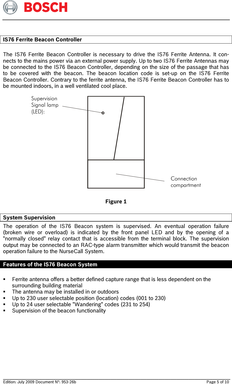
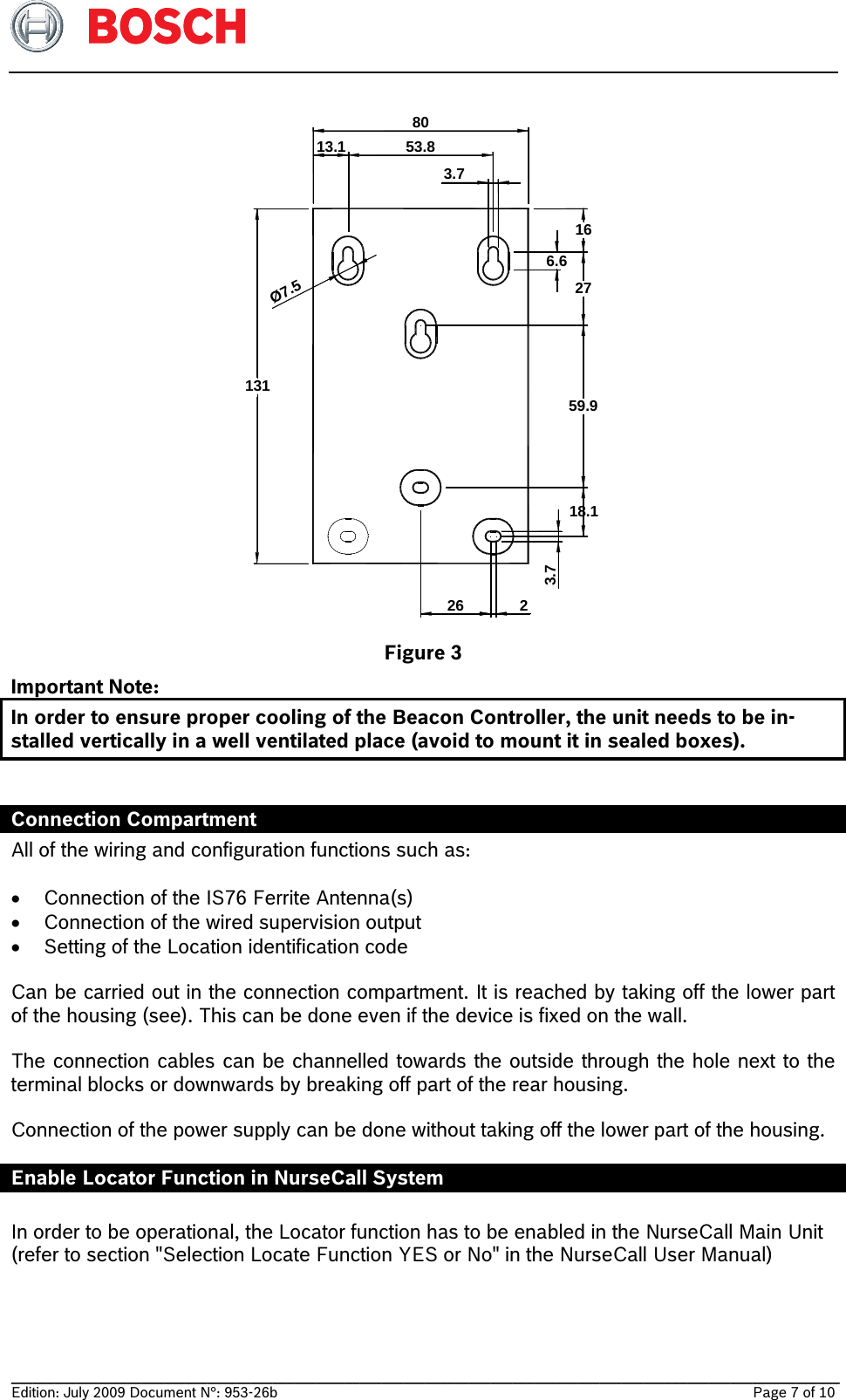
![__________________________________________________________________________________________________________________ Edition: September 2011 Document N°: 953-26b Page 6 of 10 IS76 Ferrite Antenna The Antenna is best fitted to be mounted vertically on a door's frame. In any case, the middle of the antenna should be at a height of 1 meter from the floor. The antenna has to be fixed by two screws, according to the figure below. Figure 2 Remove the cover caps at both ends of the antenna by sliding them against the outside Secure the antenna against the wall with both screws Replace the cover caps by sliding them over the housing Note: Even if the functionality of the Ferrite Beacon System is not affected by the presence of metallic items, it is not recommended to fix the antenna directly against such items. In order to avoid overheating of the IS76 Beacon Controller, install the antenna at least 1.5 cm away from metallic frames or surfaces. IS76 Beacon Controller The IS76 Beacon Controller can be fixed with two to five screws on the wall. Two holes at 60 mm interval are provided for direct mounting on connection boxes. The three upper holes are used for positioning the device and cannot be reached from the Connection Compartment. Two of the lower holes can be reached from outside and thus used for fixing the device. FCC Statement Note: This device complies with Part 15 of the FCC Rules [and with RSS-210 of Industry Canada]. Operation is subject to the following two conditions: (1) this device may not cause harmful interference, and (2) this device must accept any interference received, including interference that may cause undesired operation. Note: Changes or modifications made to this equipment not expressly approved by (manufacturer name) may void the FCC authorization to operate this equipment. 30mm +/- 1mm 540mm +/- 1mm 2 X D 5.5mm 600mm 0/-10mm](https://usermanual.wiki/Bosch-Security-Systems/CRS-NC-IS76/User-Guide-1551444-Page-6.png)