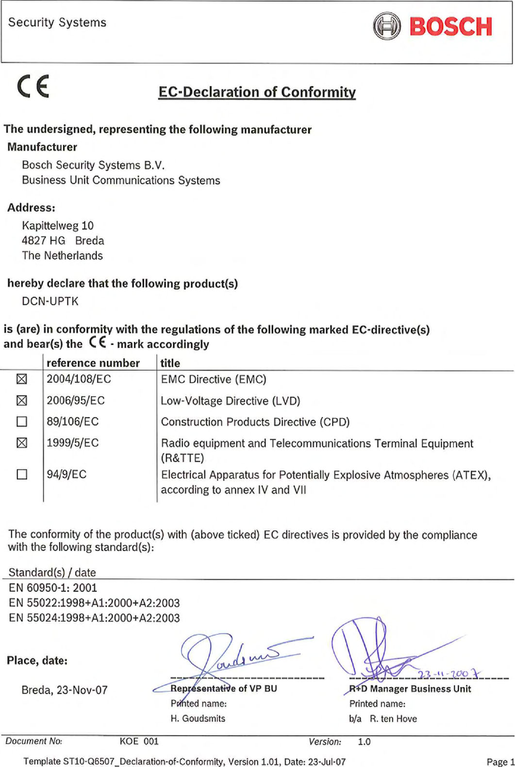
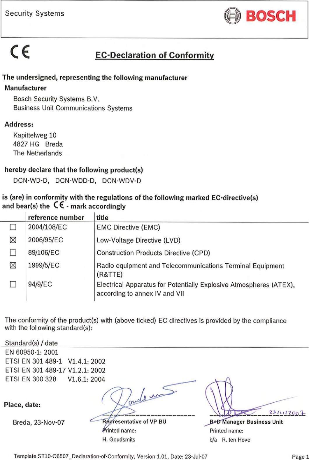
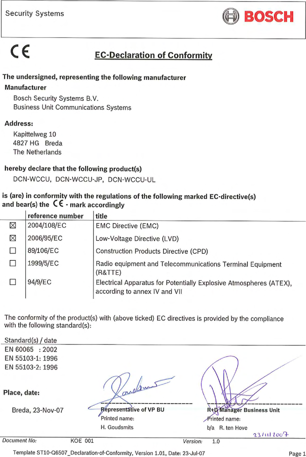
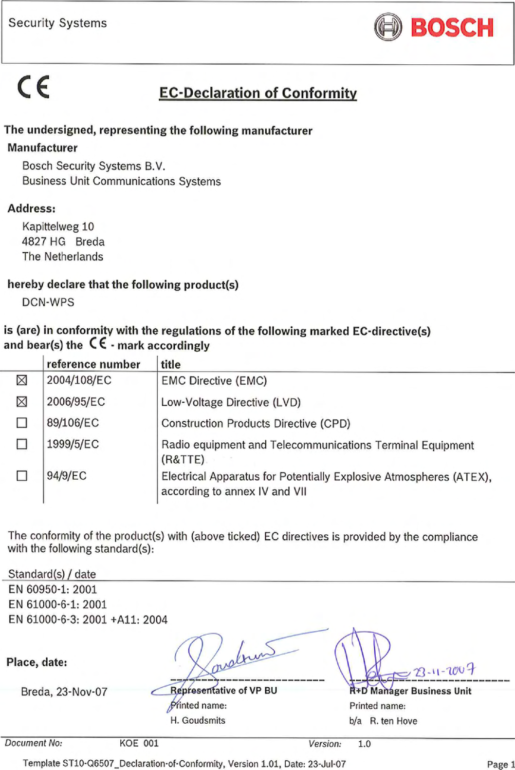
Bosch Security Systems DCNWDU02 DCN Discussion Unit User Manual

Bosch Security System BV DCN Discussion Unit

Contents

User Manual Part 2

Bosch Security Systems | 2007-11 | 9922 141 70691 enDCN Wireless | Installation and User Instructions | Contribution Devices en | 8515 DCN-MICL, DCN-MICS Pluggable Microphones15.1 IntroductionThe DCN-MICL and DCN-MICS Pluggable Microphones (refer to table 15.1 and table 15.2) are used with the contribution and interpretation devices (refer to table 15.3).15.2  Controls, connectors and indicatorsThe pluggable microphone (refer to figure 15.1) contains:1Indicator ring - Shows the condition of the microphone (refer to section 15.4).2Union nut - Attaches the pluggable microphone to the device.3Microphone plug - Connects the microphone to devices (refer to section 15.3).table 15.1: Types and lengthsType Length (mm)DCN-MICS 310DCN-MICL 480table 15.2: Electrical and acoustic propertiesNominal level:85 dB SPLMaximum level:110 dB SPL at < 3% THDTransducer type:ElectretDirectional pattern:CardioidEquivalent input noise level:24 dB(A)Power consumption:0.25 Wtable 15.3: Compatible devicesType DescriptionDCN-WD Wireless Discussion UnitDCN-WDD Wireless Discussion UnitDCN-WDV Wireless Discussion UnitDCN-IDESK Interpreter DeskDCN-FMIC Microphone control panelfigure 15.1: Overview123
Bosch Security Systems | 2007-11 | 9922 141 70691 enDCN Wireless | Installation and User Instructions | Contribution Devices en | 8615.3 External connectionsConnect the pluggable microphone to compatible devices with the microphone plug (refer to figure 15.2).15.4 OperationThe color of the indicator ring shows the condition of the microphone (refer to table 15.5).figure 15.2: Microphone plug, connectiontable 15.4: Microphone plug, connectionPin Signal1 Indicator ring, red (cathode)2Indicator ring common (anode)3 Microphone signal +4Microphone GND5Shielding6Indicator ring, green (cathode)table 15.5: ConditionColor ConditionRed (on) Microphone activeRed (flash) Last minute of speech timeGreen (on) Request-to-speakGreen (flash) First requestNoteWhen the microphone is connected to a DCN-IDESK, it can only show that the microphone is activated.612543
Bosch Security Systems | 2007-11 | 9922 141 70691 enDCN Wireless | Installation and User Instructions | Contribution Devices en | 8716 DCN-WLIION Battery Pack16.1 IntroductionThe DCN-WLIION Battery pack is used with the wireless devices (refer to table 16.4).16.2 Safetytable 16.1: Battery capacityOutput voltage:7. 2  V ( D C )Capacity:4600 mAhLife time:500 charge-discharge cyclesCharge time:3 hoursCautionUse the DCN-WCH05 Battery Charger to charge DCN-WLION Battery Packs.table 16.2: Compatible devicesType DescriptionDCN-WD Wireless Discussion UnitDCN-WDD Wireless Discussion UnitDCN-WDV Wireless Discussion Unitfigure 16.1: Safety instructionsCAUTION Important Safety Instructions for Li-ion batteries.Do not short-circuit the battery.Do not pierce or crush the battery.Do not disassemble or modify the battery.Do not heat, incinerate or expose the battery to direct continuous sunshine.Do not immerse the battery in any liquid it may be vent or rupture.Respect charging, discharging, transport and storage instructions.Charge the battery between 0 ºC and 45 ºC (32ºF and 113ºF).Discharge the battery between -20 ºC and 60 ºC (-4ºF and 140ºF).Rated : 7.2V 4800 mAhCharging Current : 12V/2.5ADCN-WLIION-D Rechargeable Lithium-ion Battery PackNL-4827HG-10S/N: SMYYWW9999Li-ionUS ITE ACCESORYCLISTED 19JWM04
Bosch Security Systems | 2007-11 | 9922 141 70691 enDCN Wireless | Installation and User Instructions | Contribution Devices en | 8816.3  Controls, connectors and indicatorsThe battery pack (refer to section figure 16.2) contains:1Capacity LEDs - Show the capacity of the battery pack (refer to section 16.5).2Clip - Locks the battery pack in, for example, a wireless discussion unit.16.4 InstallationInstall the charged battery pack in a compatible device (refer to table 16.2).16.5 OperationTo enable the capacity LEDs, press the button next to the LEDs. The higher the capacity, the higher the number of capacity LEDs that come on (refer to table 16.4).figure 16.2: Overview12table 16.3: Physical characteristicsDimensions (h x w x d):136 x 22 x 64.5 mmWeight:230 gNoteThe battery capacity in table 16.4 is plus or minus 20%.table 16.4: Capacity LEDsNo. LEDs on Battery capacity (hours)518 - 20413 - 1838 - 13 23 - 8 1< 3
Bosch Security Systems | 2007-11 | 9922 141 70691 enDCN Wireless | Installation and User Instructions | Contribution Devices en | 8917 DCN-WCH05 Battery Charger17.1 IntroductionThe DCN-WCH05 Battery Charger charges the DCN-WLIION Battery Packs. The battery charger can charge a maximum of 5 battery packs at the same time.17.2  Controls, connectors and indicators17.2.1 Front viewThe front of the battery charger (refer to figure 17.1) contains:1Ventilation grilles - Make sure that the temperature of the battery charger does not become too high.2Battery pack containers - Hold the DCN-WLIION Battery Packs.3Charge level LEDs - Show the charge level of the battery pack (refer to section 17.5).4Power on/off LED - Comes on when the power cable is connected to the mains power supply.17.2.2 Rear viewThe rear of the battery charger (refer to figure 17.1) contains:5Power inlet - Connects the battery charger to the mains power supply with a power cable (refer to section 17.4.1).6Loop-through socket - Connects the battery charger to another battery charger with a power cable (refer to section 17.4.2).figure 17.1: Overview41 2 3 5 6
Bosch Security Systems | 2007-11 | 9922 141 70691 enDCN Wireless | Installation and User Instructions | Contribution Devices en | 9017. 3  Ins t al l at i o n17.3.1 General17.3.2 WallYou can use the bracket to attach the battery charger to a wall. Refer to figure 17.2.WarningDo not open the battery charger. Electrical discharges from the battery charger can kill you.CautionDo not obstruct the ventilation grilles. A block-age of the ventilation grilles can cause a risk of fire.table 17.1: Physical characteristicsDimensions (h x w x d):340 x 195 x 82 mmWeight:1.4 kgfigure 17.2: Installation, wall020301TORX 10TORX 10
Bosch Security Systems | 2007-11 | 9922 141 70691 enDCN Wireless | Installation and User Instructions | Contribution Devices en | 91When you attach more than one battery charger to the wall, you must make sure that:• The vertical distance between two brackets is at least 340 mm (refer to d1 in figure 17.2).• The horizontal distance between two brackets is at least 195 mm (refer to d2 in figure 17.2).17.3.3 Battery17.4 External connections17.4.1 Power inletConnect a locally approved power cable to the battery charger (refer to figure 17.5).figure 17.3: Installation, multiple battery chargersd2d1figure 17.4: Installation, batteryfigure 17.5: Power inlet
Bosch Security Systems | 2007-11 | 9922 141 70691 enDCN Wireless | Installation and User Instructions | Contribution Devices en | 9217.4.2 Loop-through socketWith the loop-through socket, you can connect battery chargers in series.• If the power supply is 100 - 127 V(AC), 50 - 60 Hz, you can connect a maximum of 5 battery chargers in series.• If the power supply is 220 - 240 V(AC), 50 - 60 Hz, you can connect a maximum of 10 battery chargers in series.17. 5  Op e r at i o nThe higher the capacity, the higher the number of charge level LEDs that come on (refer to table 16.4).figure 17.6: Loop-through socketNoteThe accuracy of the battery capacity in table 16.4 is plus or minus 20%.table 17.2: Charge level LEDsNo. LEDs on Battery capacity (hours)518 - 20413 - 1838 - 13 23 - 8 1< 3
Bosch Security Systems | 2007-11 | 9922 141 70691 enDCN Wireless | Installation and User Instructions | Contribution Devices en | 9318 DCN-WPS Power Supply Adapter18.1 IntroductionThe DCN-WPS Power Supply Adapter is used with the wireless devices (refer to table 18.2).18.2 InstallationYou can change the power plug of the power supply adapter (refer to figure 18.1).18.3 External connectionsConnect the power supply adapter to compatible devices (refer to table 18.2) with the supplied cable.table 18.1: Electrical propertiesInput100 - 240 V(AC) + 10%, 50 - 60 HzOutput9 V(DC), 550 mAtable 18.2: Compatible devicesType DescriptionDCN-WD Wireless Discussion UnitDCN-WDD Wireless Discussion UnitDCN-WDV Wireless Discussion Unitfigure 18.1: Installation
Bosch Security Systems | 2007-11 | 9922 141 70691 enDCN Wireless | Installation and User Instructions | Contribution Devices en | 9419 DCN-FCWD10 Flight Case for Wireless Discussion UnitsThe DCN-FCWD10 Flight Case can accommodate:• a maximum of 10 wireless discussion units complete with battery packs and microphones (long or short stem).• 2 DCN-WCH05 charging units.The case is manufactured from a robust construction and has reinforced corners. The shaped foam interior allows for quick and easy packing of components. An extra hand grip and roller wheels are provided for convenient transportation.20 DCN-WFCCU Flight Case for DCN-WCCU and DCN-WAPThe DCN-WFCCU Flight Case provides a secure transportation and storage solution for:• a DCN-WCCU Wireless Central Control Unit, DCN-WAP Wireless Access Point and optical network cable, or• 2 DCN-WCCU Wireless Central Control Units (if dividing foam partition is removed from case).CautionDo not charge the battery packs in the flight case, otherwise you might create a fire risk.figure 19.1: DCN-FCWD10 Flight Casefigure 20.1: DCN-WFCCU Flight Case
Bosch Security Systems | 2007-11 | 9922 141 70691 enDCN Wireless | Installation and User Instructions | Contribution Devices en | 9521 DDCN-RCWD10 Roller Case for 10 Wireless DiscussionThe DCN-RCWD10 Roller Case can accommodate:• a maximum of 10 wireless discussion units with fitted microphones (long or short stem). One extra storage position can be used for a spare unit.• 2 DCN-WCH05 charging units, which slot into place and can be easily accessed by removing the side panel.The case is manufactured from a robust construction and has reinforced corners. The shaped foam interior allows for quick and easy packing of components. Roller wheels are provided for convenient transportation.CautionThe side panel must be removed during battery charging, otherwise you might create a fire risk. During charging the panel can be stored in the top lid.figure 21.1: DCN-RCWD10 Roller Case
Bosch Security Systems | 2007-11 | 9922 141 70691 enDCN Wireless | Installation and User Instructions | Contribution Devices en | 96Intentionally left blank.
Bosch Security Systems | 2007-11 | 9922 141 70691 enDCN Wireless | Installation and User Instructions | Appendices en | 97Section 4 - Appendices
Bosch Security Systems | 2007-11 | 9922 141 70691 enDCN Wireless | Installation and User Instructions | Appendices en | 98A Audio levelsA.1 DCN-WCCUA.2 DCN-WDU table A.1: Analog line inputsPlug or socket Function Nominal MaximumXLR Floor -12 dBV (- 6, + 6 dB) 12 dBV (- 6, + 6 dB)Cinch Floor -24 dBV (- 6, + 6 dB) 0 dBV (- 6, + 6 dB)table A.2: Analog outputsPlug or socket Function Nominal MaximumXLR 1 PA -12 dBV(- 24, + 6 dB) 12 dBV (- 24, + 6 dB)XLR 2 Recorder 9 dBV(- 24, + 6 dB) 12 dBV(- 24, + 6 dB)XLR 2 Equalized PA 0 dBV(- 24, + 6 dB) 12 dBV (- 24, + 6 dB))XLR 2 Insertion/ mix-minus -12 dBV(- 24, + 6 dB) 12 dBV (- 24, + 6 dB)Cinch 1 PA -24 dBV(- 24, + 6 dB) 0 dBV (- 24, + 6 dB)Cinch 2 Recorder -3dBV(- 24, + 6 dB) 0 dBV (- 24, + 6 dB)Cinch 2 Equalized PA -12 dBV(- 24, + 6 dB) 0 dBV (- 24, + 6 dB)Cinch 2 Insertion/ mix-minus -24 dBV(- 24, + 6 dB) 0 dBV (- 24, + 6 dB)table A.3: MonitorPlug or socket Function Nominal Maximum3.5 mm Headphones -1 dBV (mute, - 24 dB, 0 dB) 2 dBV (mute, - 24 dB, 0 dB)table A.4: HeadphonesPlug or socket Function Nominal Maximum3.5 mm  Headphones 3 dBV 6 dBV (mute, 0 dB)NoteFor all other audio levels, refer to the Appendix in the “DCN Next Generation, Installation & User Instructions”.
Bosch Security Systems | 2007-11 | 9922 141 70691 enDCN Wireless | Installation and User Instructions | Appendices en | 99A.3 DCN-DDItable A.5: Dual delegate interfacePlug or socket Function Nominal Maximum8-pole DIN Line in 0 dBLine in 6 dBLine in 12 dBLine in 18 dBMic 0 dBMic 6 dBMic 12 dBMic 18 dB-18 dBV (- 3, + 3 dB)-12 dBV (- 3, + 3 dB)-6 dBV (- 3, + 3 dB)0 dBV (- 3, + 3 dB)-46 dBV (- 3, + 3 dB)-40 dBV (- 3, + 3 dB)-34 dBV (- 3, + 3 dB)-28 dBV (- 3, + 3 dB)12 dBV (- 3, + 3 dB)12 dBV (- 3, + 3 dB)12 dBV (- 3, + 3 dB)12 dBV (- 3, + 3 dB)-16 dBV (- 3, + 3 dB)-16 dBV (- 3, + 3 dB)-16 dBV (- 3, + 3 dB)-16 dBV (- 3, + 3 dB)3.5 mm --- -5 dBV 7. 5  d B V
Bosch Security Systems | 2007-11 | 9922 141 70691 enDCN Wireless | Installation and User Instructions | Appendices en | 100B Product indexB.1 Central devicesB.2 Installation devicestable B.1: Central devicesProduct code Product description Refer toDCN-WCCU Central control unit wireless Page 32DCN-WCCU-UL Central control unit wireless UL Page 32DCN-EPS Extension power supply DCN Next Gen.DCN-EPS-UL Extension power supply UL DCN Next Gen.LBB4402/00 Audio expander DCN Next Gen.LBB4404/00 CobraNet Interface DCN Next Gen.PRS-4DEX4 Digital audio expander DCN Next Gen.table B.2: Installation devicesProduct code Product description Refer toLBB4114/00 Trunk splitter DCN Next Gen.LBB4115/00 Trunk splitter protected DCN Next Gen.LBB4116/00 Extension cable, 100 m DCN Next Gen.LBB4116/02 Extension cable, 2 m DCN Next Gen.LBB4116/05 Extension cable, 5 m DCN Next Gen.LBB4116/10 Extension cable, 10 m DCN Next Gen.LBB4116/15 Extension cable, 15 m DCN Next Gen.LBB4116/20 Extension cable, 20 m DCN Next Gen.LBB4116/25 Extension cable, 25 m DCN Next Gen.LBB4117/00 Cable locking clamp DCN Next Gen.LBB4118/00 Cable termination plug DCN Next Gen.LBB4119/00 DCN connectors DCN Next Gen.LBB4410/00 Network splitter DCN Next Gen.LB B4 414/10 Fiber interface without address DCN Next Gen.LBB4416/00 Network cable, 10 m DCN Next Gen.LBB4416/01 Network cable, 0.5 m DCN Next Gen.LBB4416/02 Network cable, 2 m DCN Next Gen.LBB4416/05 Network cable, 5 m DCN Next Gen.LB B4416/10 Network cable, 10 m DC N Next Gen.LBB4416/20 Network cable, 20 m DCN Next Gen.LBB4416/50 Network cable, 50 m DCN Next Gen.LBB4417/00 Network connector DCN Next Gen.LBB4418/00 Cable-connector tool kit DCN Next Gen.LBB4418/50 Spare cutting tool DCN Next Gen.LBB4419/00 Cable coupler DCN Next Gen.
Bosch Security Systems | 2007-11 | 9922 141 70691 enDCN Wireless | Installation and User Instructions | Appendices en | 101B.3 Contribution devicesB.4 Flush-mounted devicesB.5 Interpretation devicesB.6 Peripheral devicestable B.3: Contribution devicesProduct code Product description Refer toDCN-DDI Dual delegate interface Page 93DCN-DISBCM Sets of buttons for 10 chairman discussion units Page 70DCN-DISBDD Sets of buttons for 10 dual use discussion units Page 70DCN-DISR-D Set of 10 rims for discussion unit dark  Page 78DCN-DISR-SR  Set of 10 rims for discussion unit silver  Page 78DCN-DISRH-SR  Set of 10 rims for discussion unit high gloss silver Page 78DCN-DISRMH  Set of 10 rims for discussion unit high gloss metal Page 78DCN-DISRMS  Set of 10 rims for discussion unit semi gloss metal  Page 78DCN-MICL Pluggable microphone long stem Page 85DCN-MICS Pluggable microphone short stem Page 85DCN-WD-D Wireless discussion unit Page 70DCN-WDD-D Wireless dual discussion unit Page 70DCN-WDV-D Wireless discussion unit with voting Page 70DCN-WPS Power Supply Adapter Page 93table B.4: Flush-mounted devicesProduct code Product description Refer toDCN-FCS Channel selector unit for 32 channels DCN Next Gen.table B.5: Interpretation devicesProduct code Product description Refer toDCN-IDESK-L Interpreter desk for 32 channels DCN Next Gen.DCN-IDESK-D Interpreter desk for 32 channels, dark DCN Next Gen.table B.6: Peripheral devicesProduct code Product description Refer toLBB4157/00 Card encoder DCN Next Gen.DCN-IDCRD Chip cards DCN Next Gen.DCN-DDB Data distribution board DCN Next Gen.
Bosch Security Systems | 2007-11 | 9922 141 70691 enDCN Wireless | Installation and User Instructions | Appendices en | 102C Statements for FCC & Industry CanadaThis Class B digital apparatus complies with Canadian ICES-003.Cet appareil numérique de la classe B est conforme à la norme NMB-003 du Canada.The DCN-Wireless equipment has been tested and found to comply with the limits for a Class B digital device, pursuant to Part 15 of the FCC Rules. These limits are designed to provide reasonable protection against harmful interference in a residential installation.This equipment generates, uses and can radiate radio frequency energy and, if not installed and used in accordance with the instructions, may cause harmful interference to radio communications. However, there is no guarantee that interference will not occur in a particular installation. If this equipment does cause harmful interference to radio or television reception, which can be determined by turning the equipment off and on, the user is encouraged to try to correct the interference by one or more of the followingmeasures:• Reorient or relocate the receiving antenna.• Increase the separation between the equipment and receiver.• Connect the equipment into an outlet on a circuit different from that to which the receiver is connected.• Consult the dealer or an experienced radio/TV technician for help.The Wireless Discussion Units and the Wireless Access Point comply with Part 15 of the FCC Rules and with RSS-210 of Industry Canada.Operation is subject to the following two conditions:(1) this device may not cause harmful interference, and(2) this device must accept any interference received,including interference that may cause undesired operation.WarningChanges or modifications made to this equipment not expressly approved by Bosch Security Systems B.V. may void the FCC authorization to operate this equipment.NoteThe Wireless Discussion Units and the Wireless Access Point comply with FCC radiation exposure limits set forth for an uncontrolled environment. The Wireless Discussion Units and the Wireless Access Point should be installed and operated with minimum distance of 20 cm to your body. The RF-parts of the Wireless Discussion Units and the Wireless Access Point must not be co-located or operating in conjunction with any other antenna or transmitter.
Bosch Security Systems | 2007-11 | 9922 141 70691 enDCN Wireless | Installation and User Instructions | Appendices en | 103D Declarations
Bosch Security Systems | 2007-11 | 9922 141 70691 enDCN Wireless | Installation and User Instructions | Appendices en | 104
For more information visitwww.boschsecuritysystems.com© Bosch Security Systems B.V.Data subject to change without notice2007-11 | 9922 141 70691 en

Navigation menu