Bosch Security Systems DCNWDU02 DCN Discussion Unit User Manual
Bosch Security System BV DCN Discussion Unit
Contents
- 1. User Manual Part 1
- 2. User Manual Part 2
User Manual Part 2
Bosch Security Systems | 2007-11 | 9922 141 70691 en
DCN Wireless | Installation and User Instructions | Contribution Devices en | 85
15 DCN-MICL, DCN-MICS
Pluggable Microphones
15.1 Introduction
The DCN-MICL and DCN-MICS Pluggable
Microphones (refer to table 15.1 and table 15.2) are
used with the contribution and interpretation devices
(refer to table 15.3).
15.2 Controls, connectors and
indicators
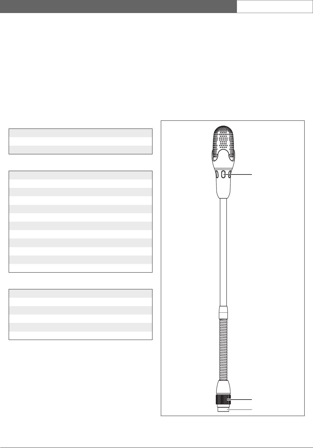
The pluggable microphone (refer to figure 15.1)
contains:
1Indicator ring - Shows the condition of the
microphone (refer to section 15.4).
2Union nut - Attaches the pluggable microphone to
the device.
3Microphone plug - Connects the microphone to
devices (refer to section 15.3).
table 15.1: Types and lengths
Type Length (mm)
DCN-MICS 310
DCN-MICL 480
table 15.2: Electrical and acoustic properties
Nominal level:
85 dB SPL
Maximum level:
110 dB SPL at < 3% THD
Transducer type:
Electret
Directional pattern:
Cardioid
Equivalent input noise level:
24 dB(A)
Power consumption:
0.25 W
table 15.3: Compatible devices
Type Description
DCN-WD Wireless Discussion Unit
DCN-WDD Wireless Discussion Unit
DCN-WDV Wireless Discussion Unit
DCN-IDESK Interpreter Desk
DCN-FMIC Microphone control panel
figure 15.1: Overview
1
2
3
Bosch Security Systems | 2007-11 | 9922 141 70691 en
DCN Wireless | Installation and User Instructions | Contribution Devices en | 86
15.3 External connections
Connect the pluggable microphone to compatible
devices with the microphone plug (refer to figure 15.2).
15.4 Operation
The color of the indicator ring shows the condition of
the microphone (refer to table 15.5).
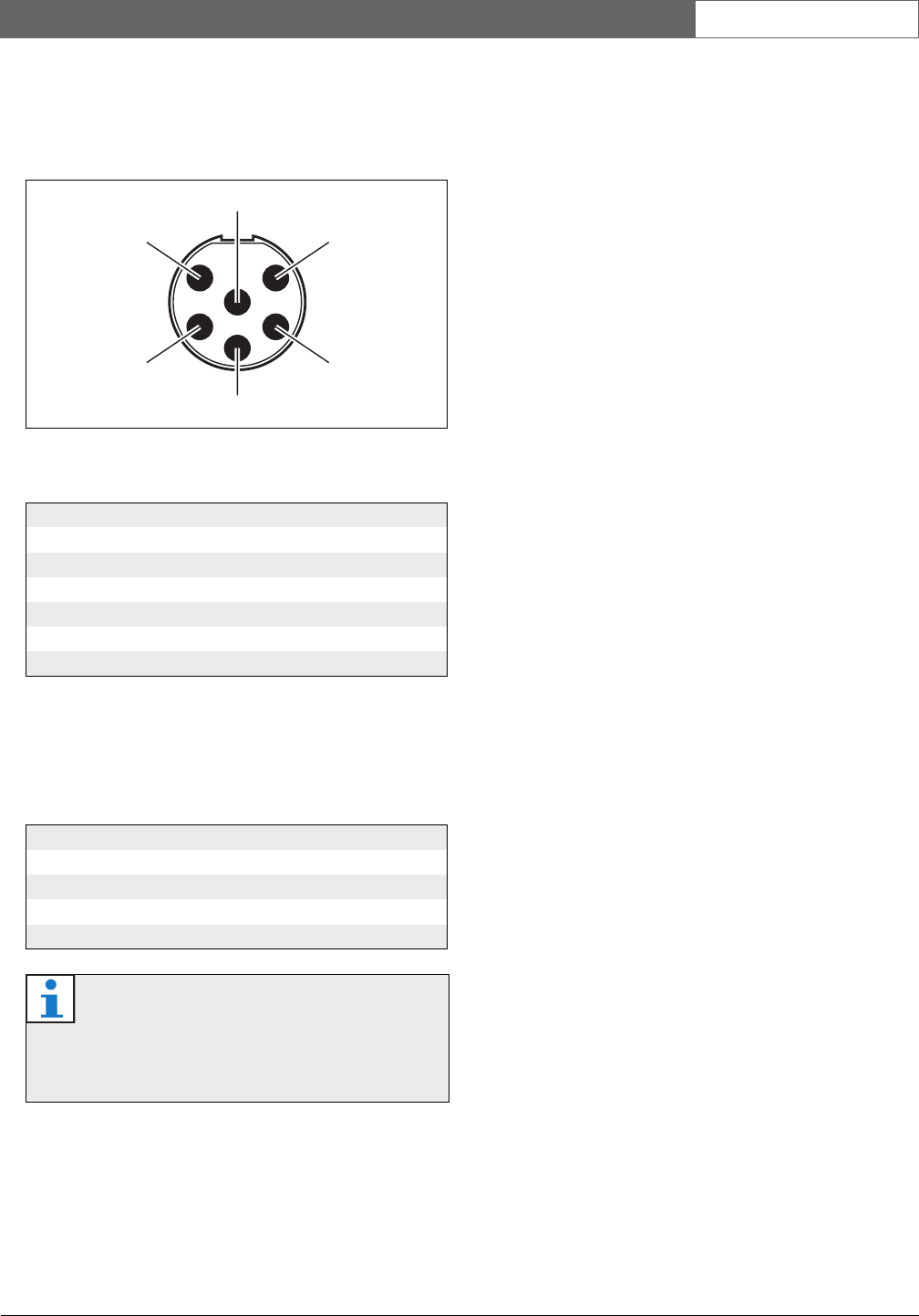
figure 15.2: Microphone plug, connection
table 15.4: Microphone plug, connection
Pin Signal
1 Indicator ring, red (cathode)
2Indicator ring common (anode)
3 Microphone signal +
4Microphone GND
5Shielding
6Indicator ring, green (cathode)
table 15.5: Condition
Color Condition
Red (on) Microphone active
Red (flash) Last minute of speech time
Green (on) Request-to-speak
Green (flash) First request
Note
When the microphone is connected to a
DCN-IDESK, it can only show that the
microphone is activated.
6
1
2
5
4
3
Bosch Security Systems | 2007-11 | 9922 141 70691 en
DCN Wireless | Installation and User Instructions | Contribution Devices en | 87
16 DCN-WLIION Battery
Pack
16.1 Introduction
The DCN-WLIION Battery pack is used with the
wireless devices (refer to table 16.4).
16.2 Safety
table 16.1: Battery capacity
Output voltage:
7. 2 V ( D C )
Capacity:
4600 mAh
Life time:
500 charge-discharge cycles
Charge time:
3 hours
Caution
Use the DCN-WCH05 Battery Charger to
charge DCN-WLION Battery Packs.
table 16.2: Compatible devices
Type Description
DCN-WD Wireless Discussion Unit
DCN-WDD Wireless Discussion Unit
DCN-WDV Wireless Discussion Unit
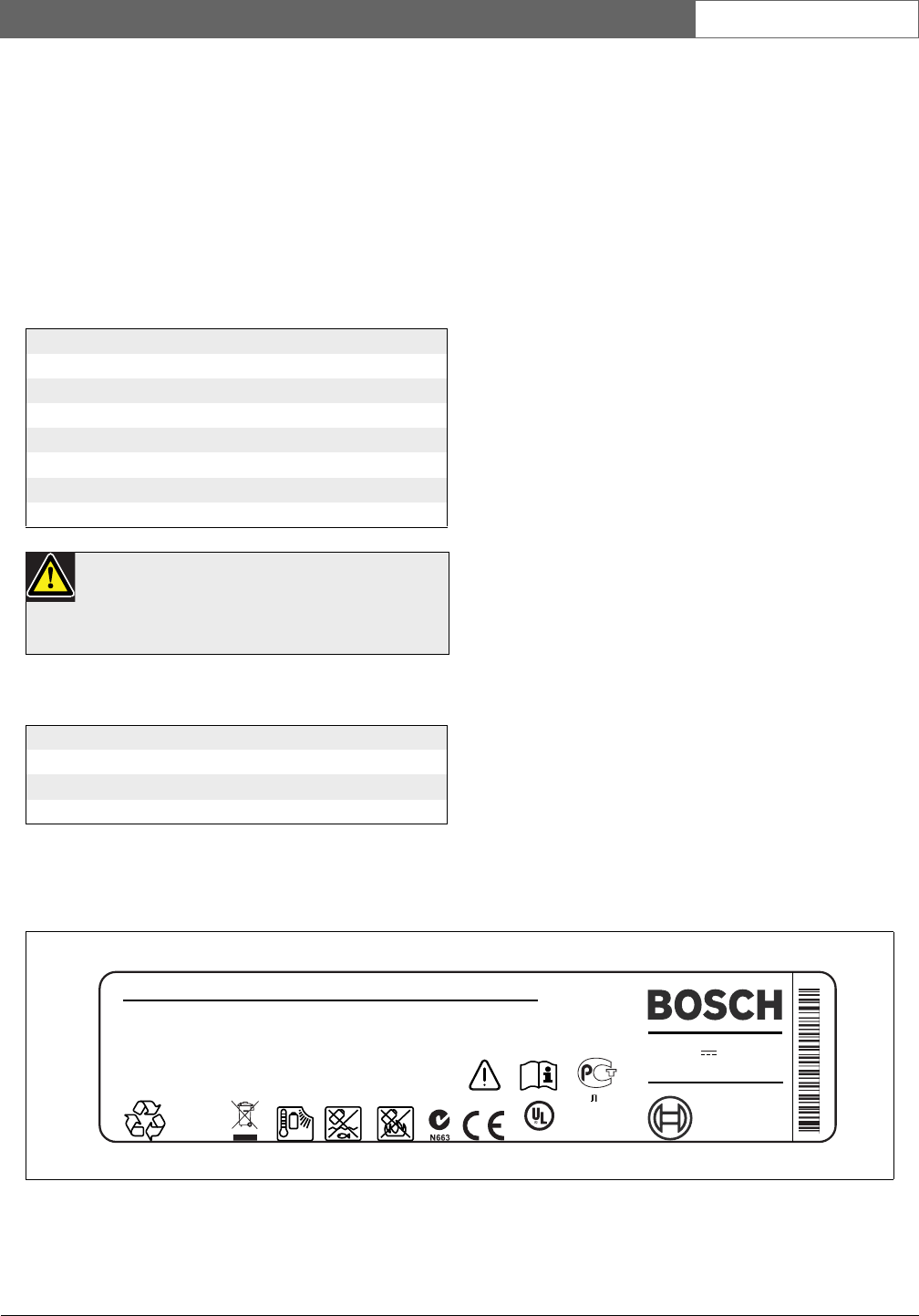
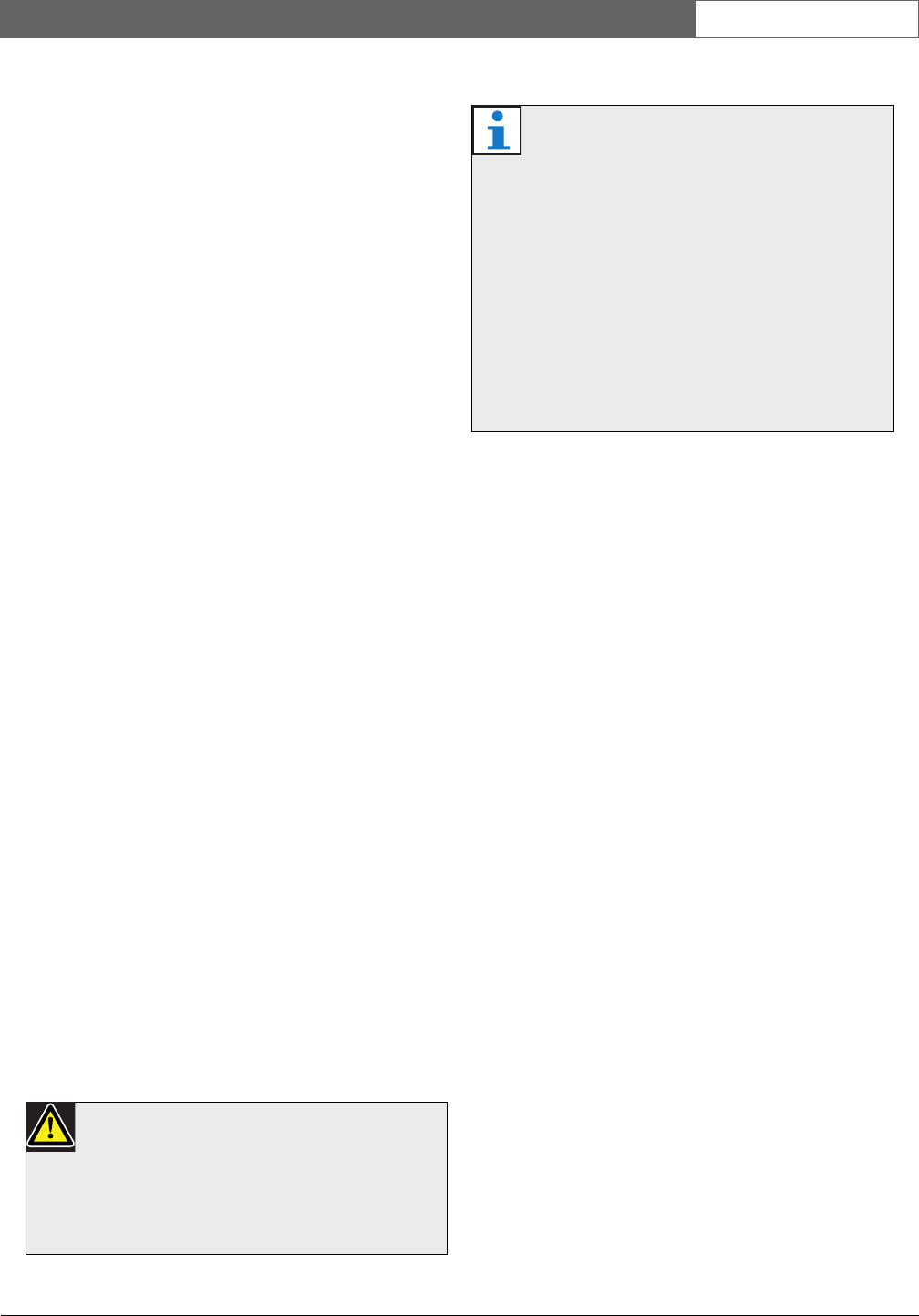
figure 16.1: Safety instructions
CAUTION Important Safety Instructions for Li-ion batteries.
Do not short-circuit the battery.
Do not pierce or crush the battery.
Do not disassemble or modify the battery.
Do not heat, incinerate or expose the battery to direct continuous sunshine.
Do not immerse the battery in any liquid it may be vent or rupture.
Respect charging, discharging, transport and storage instructions.
Charge the battery between 0 ºC and 45 ºC (32ºF and 113ºF).
Discharge the battery between -20 ºC and 60 ºC (-4ºF and 140ºF).
Rated : 7.2V 4800 mAh
Charging Current : 12V/2.5A
DCN-WLIION-D Rechargeable Lithium-ion Battery Pack
NL-4827HG-10
S/N: SMYYWW9999
Li-ion
US ITE ACCESORYC
LISTED 19JW
M
04
Bosch Security Systems | 2007-11 | 9922 141 70691 en
DCN Wireless | Installation and User Instructions | Contribution Devices en | 88
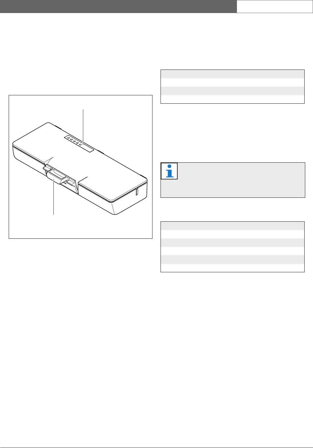
16.3 Controls, connectors and
indicators
The battery pack (refer to section figure 16.2) contains:
1Capacity LEDs - Show the capacity of the battery
pack (refer to section 16.5).
2Clip - Locks the battery pack in, for example, a
wireless discussion unit.
16.4 Installation
Install the charged battery pack in a compatible device
(refer to table 16.2).
16.5 Operation
To enable the capacity LEDs, press the button next to
the LEDs. The higher the capacity, the higher the
number of capacity LEDs that come on (refer to table
16.4).
figure 16.2: Overview
1
2
table 16.3: Physical characteristics
Dimensions (h x w x d):
136 x 22 x 64.5 mm
Weight:
230 g
Note
The battery capacity in table 16.4 is plus or
minus 20%.
table 16.4: Capacity LEDs
No. LEDs on Battery capacity (hours)
518 - 20
413 - 18
38 - 13
23 - 8
1< 3
Bosch Security Systems | 2007-11 | 9922 141 70691 en
DCN Wireless | Installation and User Instructions | Contribution Devices en | 89
17 DCN-WCH05 Battery
Charger
17.1 Introduction
The DCN-WCH05 Battery Charger charges the
DCN-WLIION Battery Packs. The battery charger can
charge a maximum of 5 battery packs at the same time.
17.2 Controls, connectors and
indicators
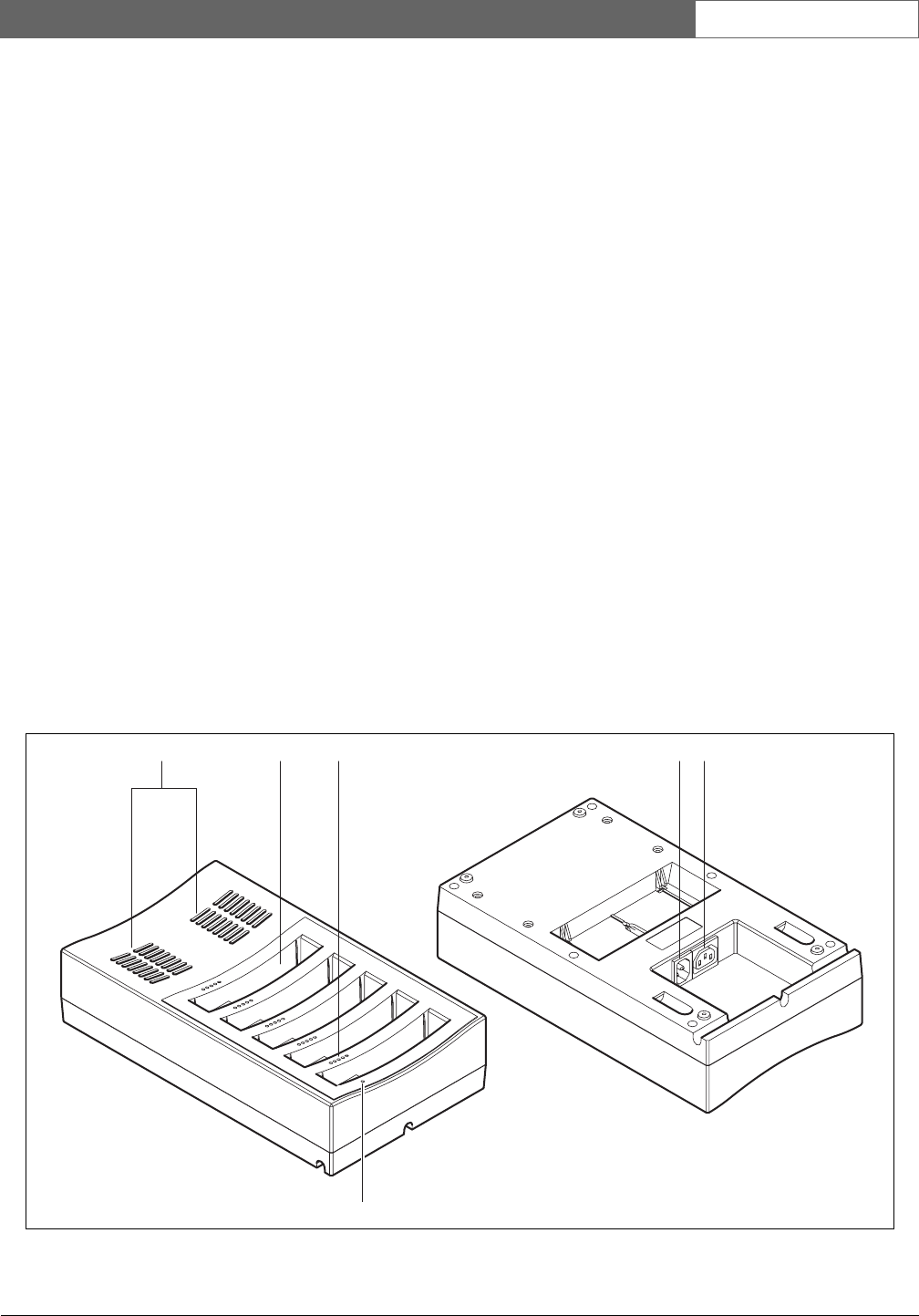
17.2.1 Front view
The front of the battery charger (refer to figure 17.1)
contains:
1Ventilation grilles - Make sure that the
temperature of the battery charger does not become
too high.
2Battery pack containers - Hold the
DCN-WLIION Battery Packs.
3Charge level LEDs - Show the charge level of the
battery pack (refer to section 17.5).
4Power on/off LED - Comes on when the power
cable is connected to the mains power supply.
17.2.2 Rear view
The rear of the battery charger (refer to figure 17.1)
contains:
5Power inlet - Connects the battery charger to the
mains power supply with a power cable (refer to
section 17.4.1).
6Loop-through socket - Connects the battery
charger to another battery charger with a power
cable (refer to section 17.4.2).
figure 17.1: Overview
4
1 2 3 5 6
Bosch Security Systems | 2007-11 | 9922 141 70691 en
DCN Wireless | Installation and User Instructions | Contribution Devices en | 90
17. 3 Ins t al l at i o n
17.3.1 General
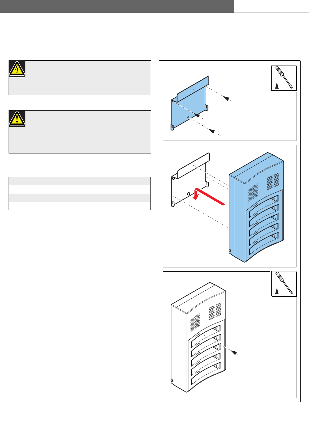
17.3.2 Wall
You can use the bracket to attach the battery charger to
a wall. Refer to figure 17.2.
Warning
Do not open the battery charger. Electrical
discharges from the battery charger can kill you.
Caution
Do not obstruct the ventilation grilles. A block-
age of the ventilation grilles can cause a risk of
fire.
table 17.1: Physical characteristics
Dimensions (h x w x d):
340 x 195 x 82 mm
Weight:
1.4 kg
figure 17.2: Installation, wall
02
03
01
TORX 10
TORX 10
Bosch Security Systems | 2007-11 | 9922 141 70691 en
DCN Wireless | Installation and User Instructions | Contribution Devices en | 91
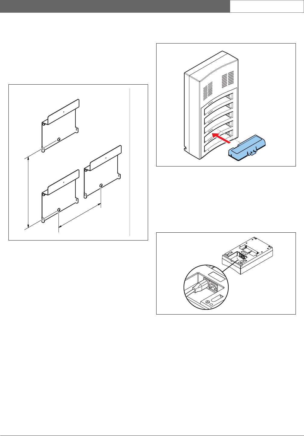
When you attach more than one battery charger to the
wall, you must make sure that:
• The vertical distance between two brackets is at least
340 mm (refer to d1 in figure 17.2).
• The horizontal distance between two brackets is at
least 195 mm (refer to d2 in figure 17.2).
17.3.3 Battery
17.4 External connections
17.4.1 Power inlet
Connect a locally approved power cable to the battery
charger (refer to figure 17.5).
figure 17.3: Installation, multiple battery chargers
d
2
d
1
figure 17.4: Installation, battery
figure 17.5: Power inlet
Bosch Security Systems | 2007-11 | 9922 141 70691 en
DCN Wireless | Installation and User Instructions | Contribution Devices en | 92
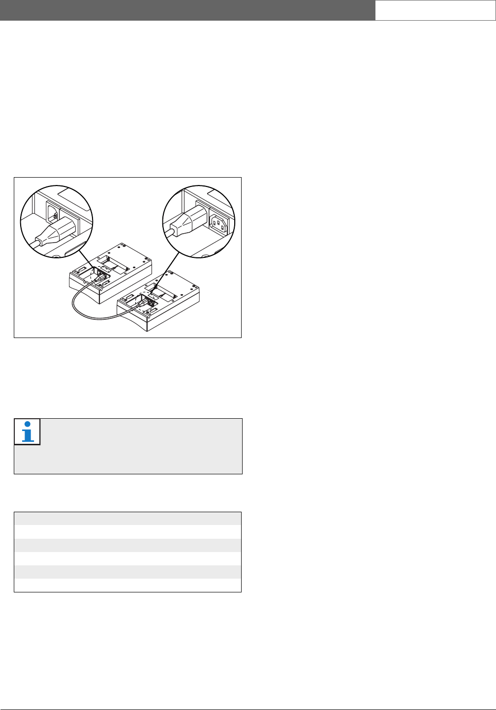
17.4.2 Loop-through socket
With the loop-through socket, you can connect battery
chargers in series.
• If the power supply is 100 - 127 V(AC), 50 - 60 Hz,
you can connect a maximum of 5 battery chargers in
series.
• If the power supply is 220 - 240 V(AC), 50 - 60 Hz,
you can connect a maximum of 10 battery chargers
in series.
17. 5 Op e r at i o n
The higher the capacity, the higher the number of
charge level LEDs that come on (refer to table 16.4).
figure 17.6: Loop-through socket
Note
The accuracy of the battery capacity in table
16.4 is plus or minus 20%.
table 17.2: Charge level LEDs
No. LEDs on Battery capacity (hours)
518 - 20
413 - 18
38 - 13
23 - 8
1< 3
Bosch Security Systems | 2007-11 | 9922 141 70691 en
DCN Wireless | Installation and User Instructions | Contribution Devices en | 93
18 DCN-WPS Power Supply
Adapter
18.1 Introduction
The DCN-WPS Power Supply Adapter is used with the
wireless devices (refer to table 18.2).
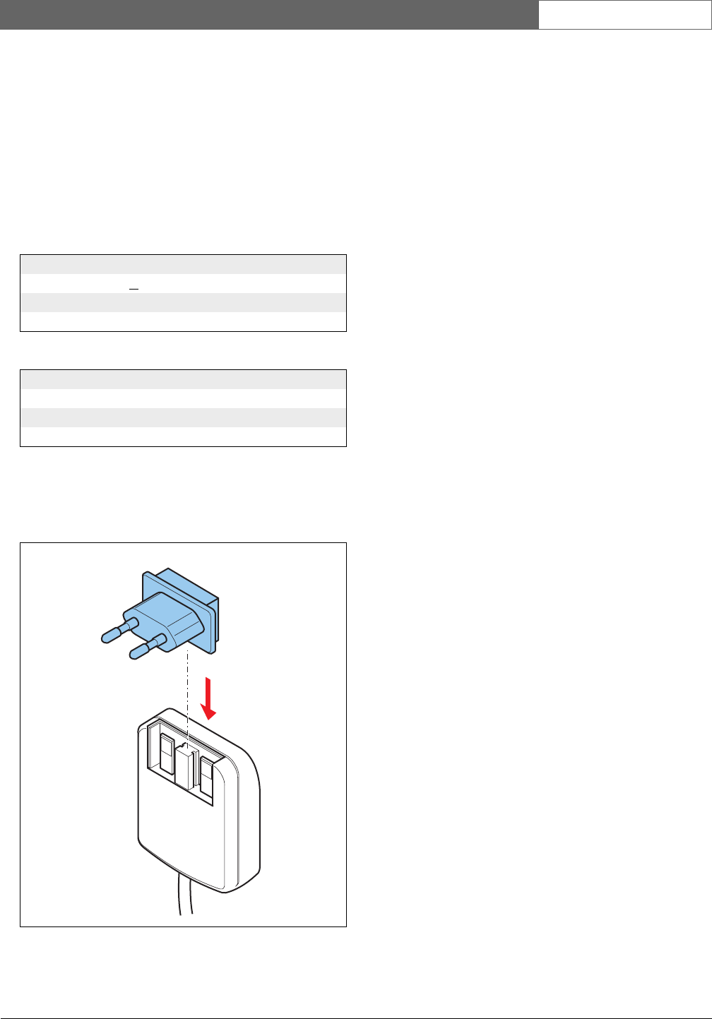
18.2 Installation
You can change the power plug of the power supply
adapter (refer to figure 18.1).
18.3 External connections
Connect the power supply adapter to compatible
devices (refer to table 18.2) with the supplied cable.
table 18.1: Electrical properties
Input
100 - 240 V(AC) + 10%, 50 - 60 Hz
Output
9 V(DC), 550 mA
table 18.2: Compatible devices
Type Description
DCN-WD Wireless Discussion Unit
DCN-WDD Wireless Discussion Unit
DCN-WDV Wireless Discussion Unit
figure 18.1: Installation
Bosch Security Systems | 2007-11 | 9922 141 70691 en
DCN Wireless | Installation and User Instructions | Contribution Devices en | 94
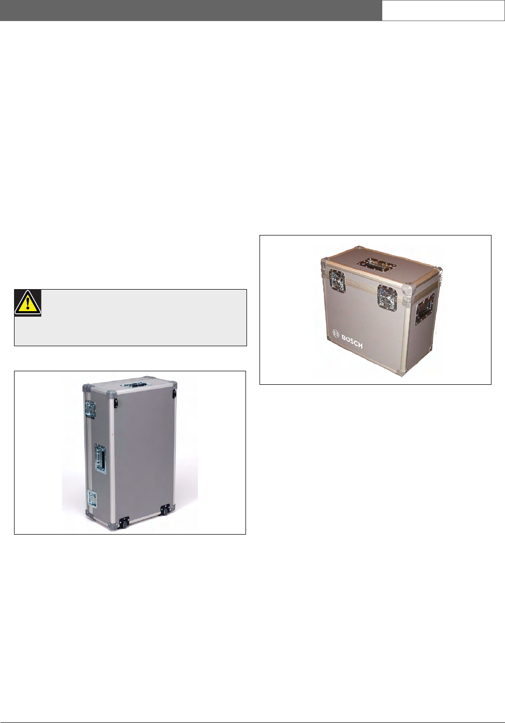
19 DCN-FCWD10 Flight Case
for Wireless Discussion
Units
The DCN-FCWD10 Flight Case can accommodate:
• a maximum of 10 wireless discussion units complete
with battery packs and microphones (long or short
stem).
• 2 DCN-WCH05 charging units.
The case is manufactured from a robust construction
and has reinforced corners. The shaped foam interior
allows for quick and easy packing of components. An
extra hand grip and roller wheels are provided for
convenient transportation.
20 DCN-WFCCU Flight Case
for DCN-WCCU and
DCN-WAP
The DCN-WFCCU Flight Case provides a secure
transportation and storage solution for:
• a DCN-WCCU Wireless Central Control Unit,
DCN-WAP Wireless Access Point and optical
network cable, or
• 2 DCN-WCCU Wireless Central Control Units (if
dividing foam partition is removed from case).
Caution
Do not charge the battery packs in the flight
case, otherwise you might create a fire risk.
figure 19.1: DCN-FCWD10 Flight Case
figure 20.1: DCN-WFCCU Flight Case
Bosch Security Systems | 2007-11 | 9922 141 70691 en
DCN Wireless | Installation and User Instructions | Contribution Devices en | 95
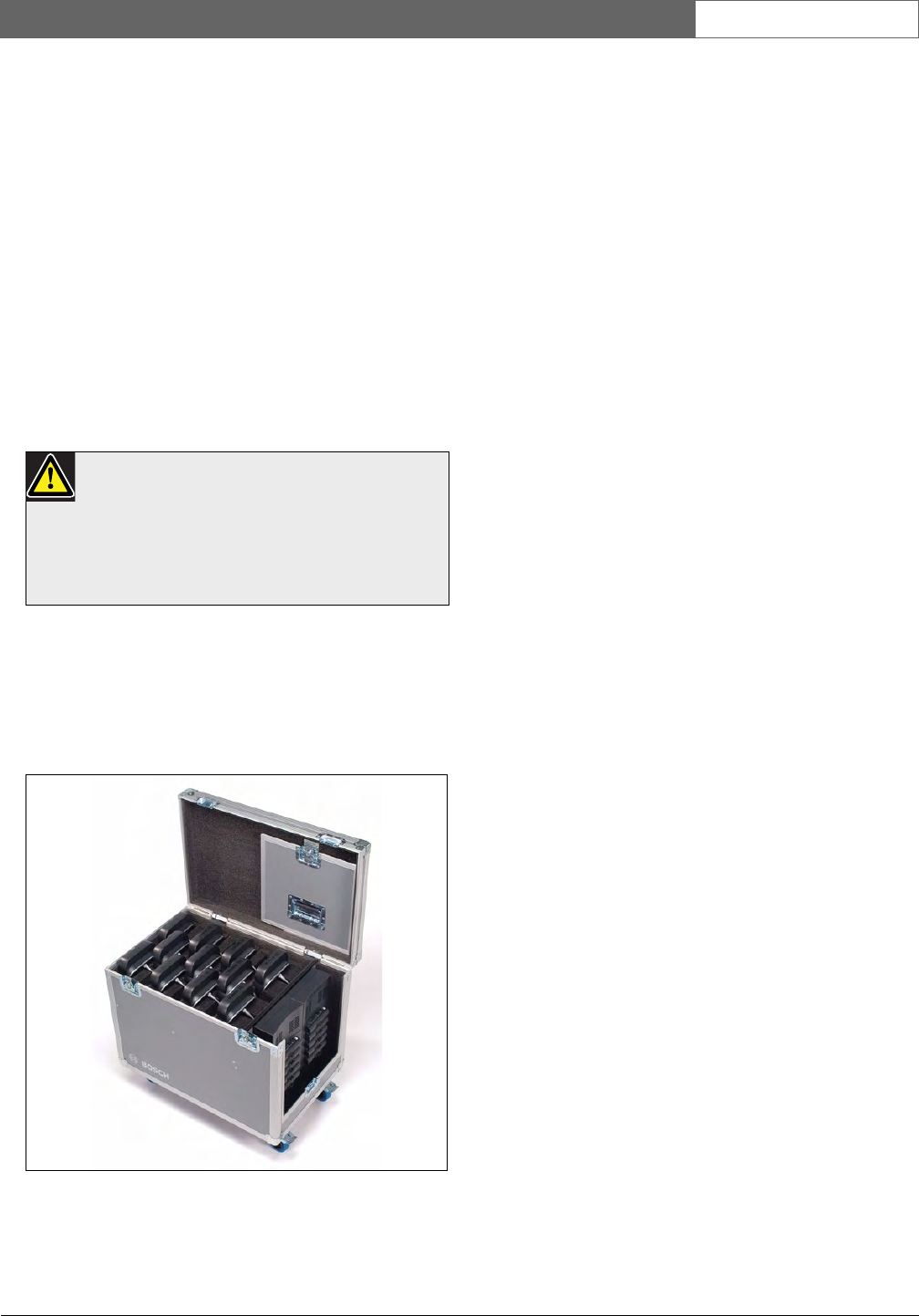
21 DDCN-RCWD10 Roller
Case for 10 Wireless
Discussion
The DCN-RCWD10 Roller Case can accommodate:
• a maximum of 10 wireless discussion units with fitted
microphones (long or short stem). One extra storage
position can be used for a spare unit.
• 2 DCN-WCH05 charging units, which slot into place
and can be easily accessed by removing the side
panel.
The case is manufactured from a robust construction
and has reinforced corners. The shaped foam interior
allows for quick and easy packing of components.
Roller wheels are provided for convenient
transportation.
Caution
The side panel must be removed during battery
charging, otherwise you might create a fire risk.
During charging the panel can be stored in the
top lid.
figure 21.1: DCN-RCWD10 Roller Case

Bosch Security Systems | 2007-11 | 9922 141 70691 en
DCN Wireless | Installation and User Instructions | Contribution Devices en | 96
Intentionally left blank.

Bosch Security Systems | 2007-11 | 9922 141 70691 en
DCN Wireless | Installation and User Instructions | Appendices en | 97
Section 4 - Appendices
Bosch Security Systems | 2007-11 | 9922 141 70691 en
DCN Wireless | Installation and User Instructions | Appendices en | 98
A Audio levels
A.1 DCN-WCCU
A.2 DCN-WDU
table A.1: Analog line inputs
Plug or socket Function Nominal Maximum
XLR Floor -12 dBV (- 6, + 6 dB) 12 dBV (- 6, + 6 dB)
Cinch Floor -24 dBV (- 6, + 6 dB) 0 dBV (- 6, + 6 dB)
table A.2: Analog outputs
Plug or socket Function Nominal Maximum
XLR 1 PA -12 dBV(- 24, + 6 dB) 12 dBV (- 24, + 6 dB)
XLR 2 Recorder 9 dBV(- 24, + 6 dB) 12 dBV(- 24, + 6 dB)
XLR 2 Equalized PA 0 dBV(- 24, + 6 dB) 12 dBV (- 24, + 6 dB))
XLR 2 Insertion/ mix-minus -12 dBV(- 24, + 6 dB) 12 dBV (- 24, + 6 dB)
Cinch 1 PA -24 dBV(- 24, + 6 dB) 0 dBV (- 24, + 6 dB)
Cinch 2 Recorder -3dBV(- 24, + 6 dB) 0 dBV (- 24, + 6 dB)
Cinch 2 Equalized PA -12 dBV(- 24, + 6 dB) 0 dBV (- 24, + 6 dB)
Cinch 2 Insertion/ mix-minus -24 dBV(- 24, + 6 dB) 0 dBV (- 24, + 6 dB)
table A.3: Monitor
Plug or socket Function Nominal Maximum
3.5 mm Headphones -1 dBV (mute, - 24 dB, 0 dB) 2 dBV (mute, - 24 dB, 0 dB)
table A.4: Headphones
Plug or socket Function Nominal Maximum
3.5 mm Headphones 3 dBV 6 dBV (mute, 0 dB)
Note
For all other audio levels, refer to the Appendix
in the “DCN Next Generation, Installation &
User Instructions”.

Bosch Security Systems | 2007-11 | 9922 141 70691 en
DCN Wireless | Installation and User Instructions | Appendices en | 99
A.3 DCN-DDI
table A.5: Dual delegate interface
Plug or socket Function Nominal Maximum
8-pole DIN Line in 0 dB
Line in 6 dB
Line in 12 dB
Line in 18 dB
Mic 0 dB
Mic 6 dB
Mic 12 dB
Mic 18 dB
-18 dBV (- 3, + 3 dB)
-12 dBV (- 3, + 3 dB)
-6 dBV (- 3, + 3 dB)
0 dBV (- 3, + 3 dB)
-46 dBV (- 3, + 3 dB)
-40 dBV (- 3, + 3 dB)
-34 dBV (- 3, + 3 dB)
-28 dBV (- 3, + 3 dB)
12 dBV (- 3, + 3 dB)
12 dBV (- 3, + 3 dB)
12 dBV (- 3, + 3 dB)
12 dBV (- 3, + 3 dB)
-16 dBV (- 3, + 3 dB)
-16 dBV (- 3, + 3 dB)
-16 dBV (- 3, + 3 dB)
-16 dBV (- 3, + 3 dB)
3.5 mm --- -5 dBV 7. 5 d B V
Bosch Security Systems | 2007-11 | 9922 141 70691 en
DCN Wireless | Installation and User Instructions | Appendices en | 100
B Product index
B.1 Central devices
B.2 Installation devices
table B.1: Central devices
Product code Product description Refer to
DCN-WCCU Central control unit wireless Page 32
DCN-WCCU-UL Central control unit wireless UL Page 32
DCN-EPS Extension power supply DCN Next Gen.
DCN-EPS-UL Extension power supply UL DCN Next Gen.
LBB4402/00 Audio expander DCN Next Gen.
LBB4404/00 CobraNet Interface DCN Next Gen.
PRS-4DEX4 Digital audio expander DCN Next Gen.
table B.2: Installation devices
Product code Product description Refer to
LBB4114/00 Trunk splitter DCN Next Gen.
LBB4115/00 Trunk splitter protected DCN Next Gen.
LBB4116/00 Extension cable, 100 m DCN Next Gen.
LBB4116/02 Extension cable, 2 m DCN Next Gen.
LBB4116/05 Extension cable, 5 m DCN Next Gen.
LBB4116/10 Extension cable, 10 m DCN Next Gen.
LBB4116/15 Extension cable, 15 m DCN Next Gen.
LBB4116/20 Extension cable, 20 m DCN Next Gen.
LBB4116/25 Extension cable, 25 m DCN Next Gen.
LBB4117/00 Cable locking clamp DCN Next Gen.
LBB4118/00 Cable termination plug DCN Next Gen.
LBB4119/00 DCN connectors DCN Next Gen.
LBB4410/00 Network splitter DCN Next Gen.
LB B4 414/10 Fiber interface without address DCN Next Gen.
LBB4416/00 Network cable, 10 m DCN Next Gen.
LBB4416/01 Network cable, 0.5 m DCN Next Gen.
LBB4416/02 Network cable, 2 m DCN Next Gen.
LBB4416/05 Network cable, 5 m DCN Next Gen.
LB B4416/10 Network cable, 10 m DC N Next Gen.
LBB4416/20 Network cable, 20 m DCN Next Gen.
LBB4416/50 Network cable, 50 m DCN Next Gen.
LBB4417/00 Network connector DCN Next Gen.
LBB4418/00 Cable-connector tool kit DCN Next Gen.
LBB4418/50 Spare cutting tool DCN Next Gen.
LBB4419/00 Cable coupler DCN Next Gen.

Bosch Security Systems | 2007-11 | 9922 141 70691 en
DCN Wireless | Installation and User Instructions | Appendices en | 101
B.3 Contribution devices
B.4 Flush-mounted devices
B.5 Interpretation devices
B.6 Peripheral devices
table B.3: Contribution devices
Product code Product description Refer to
DCN-DDI Dual delegate interface Page 93
DCN-DISBCM Sets of buttons for 10 chairman discussion units Page 70
DCN-DISBDD Sets of buttons for 10 dual use discussion units Page 70
DCN-DISR-D Set of 10 rims for discussion unit dark Page 78
DCN-DISR-SR Set of 10 rims for discussion unit silver Page 78
DCN-DISRH-SR Set of 10 rims for discussion unit high gloss silver Page 78
DCN-DISRMH Set of 10 rims for discussion unit high gloss metal Page 78
DCN-DISRMS Set of 10 rims for discussion unit semi gloss metal Page 78
DCN-MICL Pluggable microphone long stem Page 85
DCN-MICS Pluggable microphone short stem Page 85
DCN-WD-D Wireless discussion unit Page 70
DCN-WDD-D Wireless dual discussion unit Page 70
DCN-WDV-D Wireless discussion unit with voting Page 70
DCN-WPS Power Supply Adapter Page 93
table B.4: Flush-mounted devices
Product code Product description Refer to
DCN-FCS Channel selector unit for 32 channels DCN Next Gen.
table B.5: Interpretation devices
Product code Product description Refer to
DCN-IDESK-L Interpreter desk for 32 channels DCN Next Gen.
DCN-IDESK-D Interpreter desk for 32 channels, dark DCN Next Gen.
table B.6: Peripheral devices
Product code Product description Refer to
LBB4157/00 Card encoder DCN Next Gen.
DCN-IDCRD Chip cards DCN Next Gen.
DCN-DDB Data distribution board DCN Next Gen.
Bosch Security Systems | 2007-11 | 9922 141 70691 en
DCN Wireless | Installation and User Instructions | Appendices en | 102
C Statements for FCC &
Industry Canada
This Class B digital apparatus complies with Canadian
ICES-003.
Cet appareil numérique de la classe B est conforme à la
norme NMB-003 du Canada.
The DCN-Wireless equipment has been tested and
found to comply with the limits for a Class B digital
device, pursuant to Part 15 of the FCC Rules. These
limits are designed to provide reasonable protection
against harmful interference in a residential installation.
This equipment generates, uses and can radiate radio
frequency energy and, if not installed and used in
accordance with the instructions, may cause harmful
interference to radio communications. However, there is
no guarantee that interference will not occur in a
particular installation. If this equipment does cause
harmful interference to radio or television reception,
which can be determined by turning the equipment off
and on, the user is encouraged to try to correct the
interference by one or more of the following
measures:
• Reorient or relocate the receiving antenna.
• Increase the separation between the equipment and
receiver.
• Connect the equipment into an outlet on a circuit
different from that to which the receiver is
connected.
• Consult the dealer or an experienced radio/TV
technician for help.
The Wireless Discussion Units and the Wireless Access
Point comply with Part 15 of the FCC Rules and with
RSS-210 of Industry Canada.
Operation is subject to the following two conditions:
(1) this device may not cause harmful interference, and
(2) this device must accept any interference received,
including interference that may cause undesired operation.
Warning
Changes or modifications made to this
equipment not expressly approved by Bosch
Security Systems B.V. may void the FCC
authorization to operate this equipment.
Note
The Wireless Discussion Units and the Wireless
Access Point comply with FCC radiation
exposure limits set forth for an uncontrolled
environment. The Wireless Discussion Units
and the Wireless Access Point should be
installed and operated with minimum distance of
20 cm to your body. The RF-parts of the
Wireless Discussion Units and the Wireless
Access Point must not be co-located or
operating in conjunction with any other antenna
or transmitter.

Bosch Security Systems | 2007-11 | 9922 141 70691 en
DCN Wireless | Installation and User Instructions | Appendices en | 103
D Declarations

Bosch Security Systems | 2007-11 | 9922 141 70691 en
DCN Wireless | Installation and User Instructions | Appendices en | 104