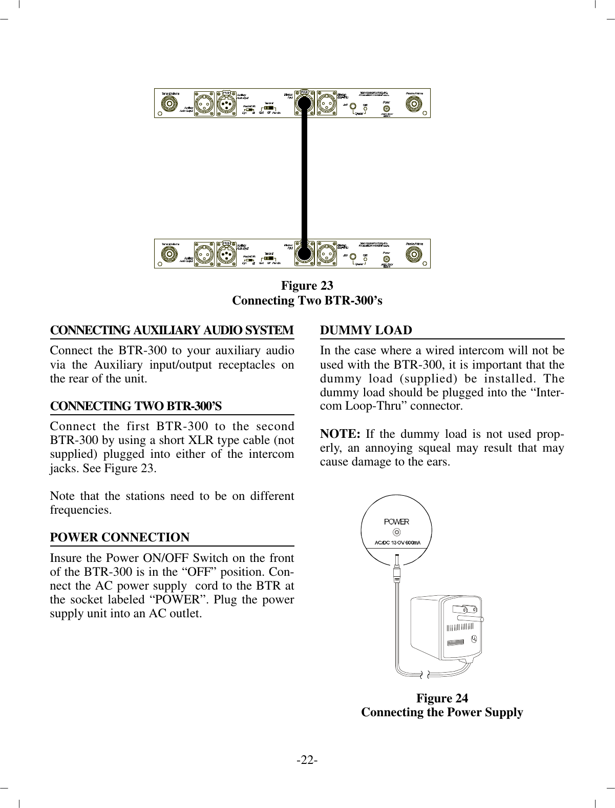
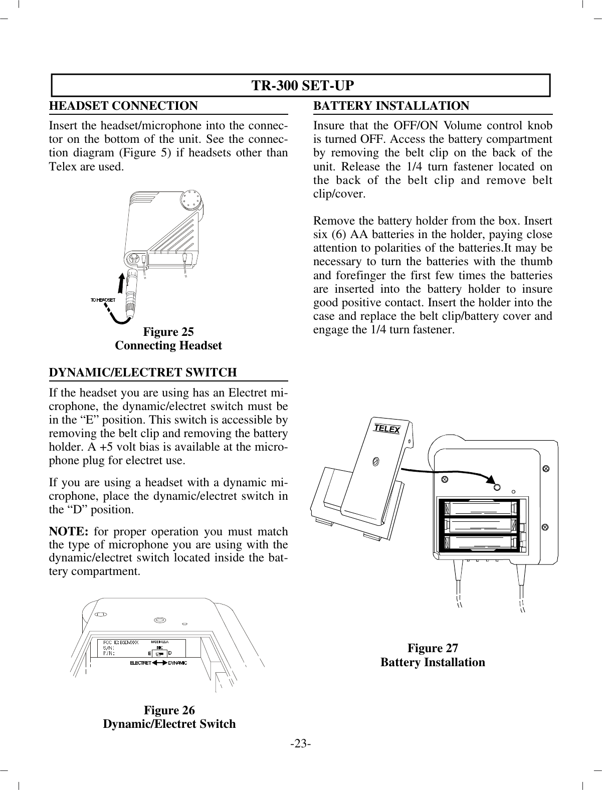
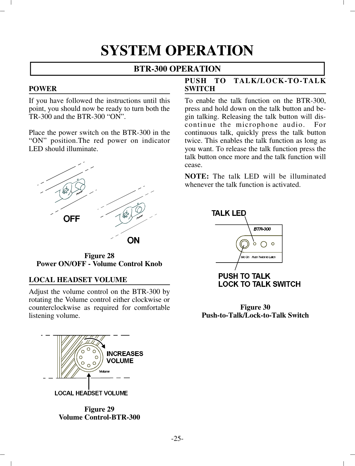
Bosch Security Systems M511 Wireless Microphone Base Station Transmitter User Manual tr300

Bosch Security Systems, Inc. Wireless Microphone Base Station Transmitter tr300

NOT the Test Report

TelexOp er ating  In struc tionsPRO FES SIONALWIRELESSIN TER COM SYS TEMTR-300, TR-300P,BTR-300
TA BLE  OF CON TENTSIN TRO DUC TION ..............................................................................................................................1GEN ERAL DE SCRIP TION............................................................................................................1BTR-300 BASE STATION TRANS CEIVER..................................................................................3TECH NI CAL IN FOR MA TION......................................................................................................3SPEC I FI CA TIONS..................................................................................................................3FEA TURES..............................................................................................................................4CON TROLS AND CON NEC TIONS..............................................................................................5FRONT PANEL................................................................................................... ....................5REAR PANEL................................................................................................... ......................6TR-300 BELT-PACK TRANS CEIVER...........................................................................................9TECH NI CAL IN FOR MA TION......................................................................................................9SPEC I FI CA TIONS..................................................................................................................9FEA TURES............................................................................................................................10CON TROLS AND CON NEC TIONS............................................................................................10EX TER NAL CON TROLS  ...................................................................................................10IN TER NAL CON TROLS.....................................................................................................12EQUIP MENT SET-UP....................................................................................................................13UN PACKING................................................................................................................................13AN TENNA IN FOR MA TION........................................................................................................13AN TENNA CON NEC TIONS...............................................................................................13AN TENNA PO LAR IZA TION..............................................................................................14DIS TANCE BE TWEEN AN TENNAS.................................................................................14AN TENNA PLACE MENT...................................................................................................15IM PROVING RE CEP TION/IN CREASING RANGE..........................................................16BTR-300 SET-UP..........................................................................................................................17LO CA TION ............................................................................................................................17IN TER NAL IN TER COM SWITCHES.................................................................................17RACK MOUNTING..............................................................................................................19LO CAL HEAD SET CON NEC TION....................................................................................21HEAD SET MIC SE LECT SWITCH.....................................................................................21TRANS MIT SWITCH................................................................................................... ........21IN TER CON NEC TION TO A HARD-WIRED IN TER COM...............................................22AUX IL IARY AU DIO CON NEC TION.................................................................................23POWER CON NEC TION................................................................................................... ....23DUMMY LOAD....................................................................................................................23TR-300 SET-UP................................................................................................... ..........................24HEAD SET CON NEC TION..................................................................................................24DY NAMIC/ELECTRET MIC SWITCH..............................................................................24BAT TERY IN STAL LA TION................................................................................................25-i-
TA BLE OF CON TENTS (CONT.)PRE-WALK-THRU CHECK LIST................................................................................................26SYS TEM OP ER A TION..................................................................................................................27BTR-300 OP ER A TION................................................................................................... ..............27POWER ..................................................................................................................................27LO CAL HEAD SET VOL UME.............................................................................................27PUSH TO TALK/LOCK TO TALK SWITCH......................................................................27TR-300 OP ER A TION....................................................................................................................28POWER ..................................................................................................................................28BAT TERY CHECK................................................................................................... ............28HEAD SET VOL UME................................................................................................... ........28PUSH TO TALK/PUSH TO TRANS MIT SWITCH............................................................28BAT TERY RE MOVAL................................................................................................... ......29EN ABLING AU DIO................................................................................................... ..................30POR TA BLES................................................................................................... ......................30WIRED IN TER COM................................................................................................... ..........30AUX IL IARY ..........................................................................................................................30SETTING SYS TEM GAIN LEVELS...........................................................................................31AD JUSTING GAIN................................................................................................... ............31BTR-200 BASE STATION................................................................................................... .31TR-200 POR TA BLE..............................................................................................................31IN TER COM GAIN................................................................................................................32AUX IL IARY GAIN................................................................................................... ............32SYS TEM WALK-THRU................................................................................................... ..............33TROU BLE SHOOTING................................................................................................... ..............34BAT TERY IN FOR MA TION..........................................................................................................35GEN ERAL................................................................................................... ..................................35BC-4 BAT TERY CHARGER........................................................................................................35REC OM MENDED HEAD SETS................................................................................................... .36AC CES SORIES................................................................................................... ............................38WAR RANTY SER VICE IN FOR MA TION...................................................................................40FCC IN FOR MA TION................................................................................................... ..................41-ii-
IN TRO DUC TIONGEN ERAL DE SCRIP TIONThis man ual cov ers the BTR-300 Base Sta tionand the TR-300 Por ta ble  Trans ceiver.The Telex Models BTR-300 and TR-300 werespe cif i cally de signed to pro vide the user with a highly flex i ble wire less  two-way com mu ni ca -tion sys tem with the ca pa bil ity of in ter facewith a wired in ter com sys tem and other aux il -iary  au dio. At the BTR-300 op er a tor’s com mand, theremotes may com mu ni cate with each other,with a wired in ter com sys tem or with an aux il -iary sys tem. The BTR-300 Base Sta tion withits  one trans mit and four re ceive chan nels isde signed to  op er ate in full du plex (si mul ta -neous two-way com mu ni ca tions) with up tofour TR-300 Belt Pack trans ceiv ers. See blockdi a gram in Fig ure 1.Fig ure 1Block Di a gram of Sys tem-1-
The sys tem op er ates on se lected fre quen cieswithin the 150-216 MHz band.The BTR-300 sys tem is fully com pat i ble with a num ber of  other wired in ter com man u fac tur ersunits. See the BTR-300 Setup Sec tion for ad di -tional in for ma tion.The TR-300 Trans ceiver op er ates in the con tin -u ous trans mit mode with the au dio ac ti vated by a switch. As many as four TR-300 belt-packtrans ceiv ers can op er ate in a fully du plex net -work with one Telex Model BTR-300 BaseSta tion.The TR-300P Trans ceiver op er ates in thePush-to-transmit mode (the trans mit and talkfunc tion are ac ti vated  to gether). Any num berof TR-300P trans ceiv ers can be used in ahalf-duplex net work with one BTR-300 BaseSta tion. Op er ate only one TR-300P at a time.At tempting to use two trans mit ters si mul ta -neously on the same chan nel will cause in ter -fer ence.-2-
BTR-300 BASE STATION TRANS CEIVERTECH NI CAL IN FOR MA TION-3-SPEC I FI CA TIONS BTR-300Over allIn put Power.......................................................................  13.0 VAC RMS/600 mA with sup plied adap toror fil tered 12 to 14 VDC/600 mA source.In ter com Out put  .........50 mV (Low) or 330 mV (Hi) RMS into 300 ohm load typ i cal (at rated de vi a tion)In ter com In put  (Gain Min i mum).............................................  300 mV RMS typ i cal (for rated de vi a tion)Aux il iary Out put  ...........................................430 mV RMS into 600 ohm load typ i cal (at rated de vi a tion)Aux il iary In put  (Gain Max i mum).............................................  60 mV RMS typ i cal (for rated de vi a tion)Lo cal Head set In put...........................................................................................  2 mV RMS in put nom i nal1.5 mV RMS in put at com pres sion (Dy namic)Lo cal Head set Out put.................................................................  32 mW max i mum out put into 600 ohmstTem per a ture Range....................................................................................... -4°F to 130°F (-20°C to 55°C)Di men sions....................................................................................................15.75" W x 1.75" H x 10.5" D(40 cm x 4.5 cm x 26 cm)Weight....................................................................................................................................... 4.5 lbs (2 kg)Trans mitRF Fre quency Range.............................................................................................................   150-216 MHzRF Fre quency Sta bil ity....................................................................................   Crys tal Con trolled, 0.005%RF Power Out put................................................................................................... .............   50 mW Typ i calMod u la tion................................................................................................... .............   FM, 3 KHz de vi a tion.115 mi cro-seconds Pre-emphasisTrasmit An tenna................................................................................................... ........  5/8-wave (sup plied)SO239 con nec tor on chas sisMod u la tion Lim iter................................................................................................... .... In ter nal Com pres sorMod u la tion Fre quency Range...................................................................................300 to 5000 Hz ±2  dBRa di ated Har monics and Spu ri ous Emis sions................................................................................. -45 dBC,Ex ceeds FCC Spec i fi ca tionsFCC  ................................................................................................  Type Ac cepted Un der Parts 90 and 74
FEA TURESThe Telex Model BTR-300 is a Base Sta tionwith one  trans mit ter and four re ceiv ers. It is de -signed for por ta ble two way com mu ni ca tionwith the ca pa bil ity for in ter face to other au diosys tems. Fea tures in clude:•An ex tremely flex i ble unit that  has the  ca -pa bil ity to com mu ni cate at one time withany num ber of the  avail able por ta ble  sta -tions (up to four) or wired sta tions  (in ter -com and/or other au dio source).•Powered by an ex ter nal AC sup ply  via thepower jack on the rear of the unit. It  canalso be pow ered by any fil tered 12 to 14VDC/600 mA  source or 13.0 VAC RMS600 mA source.•In ter com con nec tions with the abil ity to in -ter face with most wired in ter com sys tems.•RF LED in di ca tor for each por ta ble sta tion.•All metal case for su pe rior shield ing.•Ta ble or rack mount able.-4-SPEC I FI CA TIONS BTR-300 (CONT.)Re ceive RF Fre quency Range............................................................................................................... 150-216 MHzRF Fre quency Sta bil ity......................................................................................Crys tal Con trolled, 0.005%Type................................................................................................. Dual Con ver sion super het ero dyne, FMRF Sen si tiv ity......................................................................................   Less than 0.5 µV for 12 dB SINADIF Se lec tiv ity.............................................................................  3 dB at 30 kHz (4 pole Monolythic Fil ter)Im age Re jec tion................................................................................................... ................  65 dB or betterSquelch Quieting.................................................................................................................................. 90 dBSquelch Thresh old............................................................................................................   1.0 µV (In ter nal)Sig nal-to-Noise Ra tio........................................................................................................................... 90 dBRe ceive An tenna..........................................................................................................   5/8-wave (sup plied)SO239 con nec tor on chas sisDis tor tion................................................................................................... ..   Less than 1% at Rated Out put
CON TROLS and CON NEC TIONSFRONT PANEL ( Re fer to Fig ure 3)Power ON/OFF Switch:Push this switch once to  turn power ON; push it again to turn thepower OFF.Power ON In di ca tor: The Power ON In di ca -tor is il lu mi nated when the Power ON/OFFSwitch is pushed in the ON  Po si tion. Lo cal Head set Con nec tor: 4 Pin XLR Con -nec tor for In put/Out put. The head set jack willac cept many Telex  model head sets. Com pat i ble with other in ter com head sets with four pinXLR con nec tors that are wired as  shown inFig ure 2.Fig ure 2Head set XLR Con nec tor WiringLo cal Head set Vol ume: Ad justs vol ume toLo cal Head set.DOES NOT AF FECTMI CRO PHONE GAIN.Mic On-Push-to-Talk/Lock-to-Talk Switch:En ables the lo cal head set mi cro phone au diofunc tion. NOTE: DOES NOT  con trol base sta tion RFtrans mit.Lo cal Push-to-Talk In di ca tor:  Will be il lu mi -nated when ever  the talk func tion is on.Lo cal Mi cro phone Gain Con trol and Overmodulation In di ca tor: A screw driverad just able con trol is pro vided to con trol the  in -put level of the lo cal head set mic. This in put ispro tected from over loads by means of a gaincom pres sor whose  op er a tion is sig naled by thegain LED in di ca tor. Por ta ble En able Switches and In di ca tors:When in the “IN” po si tion, the En able switches al low the user of the  cor re spond ing por ta bleunit to be heard by oth ers con nected to the sys -tem. When in the “OUT” po si tion, the re spec -tive  por ta ble will be muted, but this por ta blewill still be able to hear all other se lectedremotes and in ter faces. The in di ca tors nor -mally show the pres ence of a por ta ble trans -ceiver in use on the chan nel cor re spond ing tothat in di ca tor. -5-
External In ter com Switch, Level Con trol,and In di ca tor: This switch en ables the wiredin ter com in ter face when “IN”, and dis ables itwhen “OUT”. For RTS in ter coms, the “IN” po -si tion  is chan nel A and the “OUT” po si tion ischan nel B. A  screw driver ad just able con trol ispro vided to con trol the  in put level of the wiredin ter com. Aux il iary Au dio En able Switch, Level Con -trol, and In di ca tor: The switch en ables anddis ables the Aux il iary in ter face when “IN” and“OUT”, re spec tively. The func tion  of the levelcon trol here is the same as that de scribed forthe in ter com. REAR PANEL (Re fer to Fig ure 4)Trans mit and Re ceive An tenna Con nec tors:At tach 5/8-wave an tenna s  (sup plied) to thesecon nec tors. An tenna color should match the“color dot.”Trans mit Switch: Slide switch that al lows theop er a tor to  se lect one of three trans mit modes.In the “OFF” po si tion, the trans mit ter is al ways off. This mode may be used if the  base is func -tion ing solely as a mon i tor. In the “CONT”  po -si tion, the trans mit ter is al ways on. Thiscon tin u ous mode is rec om mended over the“RE MOTE” mode. In the “RE MOTE” po si -tion, the trans mit ter is en abled only when oneor more portables are ac tive.Head set Mi cro phone Se lect Switch:Thisswitch al lows the user to se lect ei ther anElectret or Dy namic mi cro phone.In ter com Con nec tors:  Con nec tions to in ter -face the BTR-300  with a wired in ter com sys -tem. Aux il iary Out put/In put Con nec tors:  Can beused for 2-way  (four wire) in put and out put tothe BTR-300 or as a sim plex  in put or out put.Typ i cal uses are 4 wire low level in ter com’s,tape re cord ers, pub lic ad dress in puts or out -puts, or when op er at ing two BTR-300 units si -mul ta neously.Power Jack: For ex ter nal AC sup ply adap tor(sup plied) or any fil tered 12 to 14 VDC/600mA source, or 13.0 VAC  RMS/600 mA source.Speaker Jack: Al lows the user to con nect anex ter nal speaker  (8 ohms min i mum) to the unit.Speaker Gain Con trol: Screw driver ad just -able. Ad just the  gain con trol clock wise to in -crease speaker gain or coun ter clock wise tode crease speaker gain. NOTE:  Leave set ting coun ter clock wise if nospeaker is at tached.-6-
-7-
-8-
TR-300 BELT-PACK TRANS CEIVERTECH NI CAL IN FOR MA TION-9-SPEC I FI CA TIONS TR-300Over allPower Re quire ments...................................................................   6 AA cells (Al ka line, NEDA, MN 1500)Nickel-Metal Hydride Op tionalCur rent Drain................................................................................................... .....................   typ i cal 65 mATem per a ture Range.....................................................................................   -4 oF to 130oF (-20 oC to 55 oC)Di men sions....................................................................................................  4.25" W x 4.125" H x 2.0" D(108mm x 105mm x 51mm)Weight................................................................................................................  13oz (369g) with bat ter iesTrans mit An tenna.................................................................................................   1/4-wave wire (at tached)Re ceive An tenna..................................................................................................   1/4-wave wire (at tached)Trans mitRF Fre quency Range................................................................................................... ..........  150-216 MHzRF Fre quency Sta bil ity....................................................................................   Crys tal Con trolled, 0.005%RF Power Out put................................................................................................................  50 mW Typ i calMod u la tion............................................................................................................   FM, 5000 Hz de vi a tion,115 mi cro-seconds Pre-emphasisMod u la tion Lim iter.....................................................................................................  In ter nal Com pres sorMod u la tion Fre quency Range  ...............................................................................  300 to 5000 Hz +/-2dBMi cro phone Au dio In put...................................................................................................   30 to 3500 ohmsMi cro phone In put Sen si tiv ity.....................................................................  2 mV Dy namic, 4 mV ElectretRa di ated Har monics and Spu ri ous Emis sions...............................................................................   -45 dBC,Ex ceeds FCC Spec i fi ca tionsFCC  ................................................................................................   Type Ac cepted Un der Parts 90 and 74Re ceiveRF Fre quency Range................................................................................................... ..........  150-216 MHzRF Fre quency Stabiltiy............................................................................   Crys tal Con trolled, 0.005%TypeDual Conversion Superheterodyne, FMRF Sen si tiv ity......................................................................................  Less than 0.5 µV for 12 dB SINADIF Se lec tiv ity.............................................................................................  3 dB at 30 kHz (Ce ramic Fil ter)Im age Re jec tion...................................................................................................................   70 dB or betterSquelch Quieting................................................................................................... ............................... 90 dBSquelch Thresh old.............................................................................................................   3.0 µV (In ter nal)Sig nal-to-Noise Ra tio................................................................................................... ........................ 90 dBAu dio Out put...........................................................................................  32 mW into 600 ohms (Head set)Dis tor tion.....................................................................................................  Less than 1% at Rated Out put
FEA TURES•Light weight, small size and i s self-contained.•2 sep a rate an ten nas, one for trans mit, theother for re ceive.•Push-to-Talk with Lock-to-Talk fea tureswitch  for the TR-300 and Push-to-Transmitwith Lock-to-Transmit fea ture for theTR-300P.CON TROLS AND CON NEC TIONSEX TER NAL  CON TROLS (Re fer  to  Fig ure 6)Vol ume OFF/ON Con trol: This thumbwheelcon trol serves as  both an off/on switch and as a vol ume con trol. Low Bat tery and Overmodulation  In di ca tor LED:Low Bat tery In di ca tor :   Part of the bat terycheck cir cuit. When the power switch isplaced in the “ON”  po si tion the LED willflash one time if the bat tery is good. A poorbat tery will cause the LED to il lu mi nate con -tin u ously  and a bad or un us able bat tery willnot cause any  il lu mi na tion at all.Overmodulation In di ca tor: Uses the sameLED as  the low bat tery in di ca tor. Dur ing thetalk mode, if the mi cro phone gain is toohigh, the LED will il lu mi nate when  talk ing. Push-To-Talk/Lock-To-TalkSwitch: ForModel TR-300, this switch en ables the talkfunc tion. For Model TR-300P, this  switch en -ables the trans mit and au dio func tion and oth -er wise  op er ates as de scribed for BTR-300.Talk LED In di ca tor: (La beled “talk”) Will beil lu mi nated  when ever the talk func tion on theTR-300 or trans mit func tion on the TR-300P is en abled.Head set Jack: A four pin XLR con nec tor forIn put/Out put. The head set jack will ac ceptmany dif fer ent Telex model head sets. Com pat i -ble with other in ter com head sets with four pinXLR  con nec tors that are wired as shown inFig ure 5.Charge Jack: Al lows nickle-metal hy dridebat ter ies to be charged with out re mov ing themfrom the unit.Fig ure 5Head set XLR Con nec tor Wiring-10 -
Fig ure 6Ex ter nal Con trols, TR-300-11 -
Fig ure 7In ter nal Con trols, TR-300IN TER NAL CON TROLS (Re fer  To  Fig ure 7)Mi cro phone Gain Con trol:  Screw driver ad -just able by re mov ing  belt clip and pry ing outthe small rub ber plug to the right of the screwboss.Dy namic/Electret Switch: This switch al lowsse lec tion of “D” when us ing a Dy namic Mi cro -phone or "E" when us ing an  Electret Mi cro -phone.Bat tery Com part ment:  Holds 6 AA bat ter iesin a re mov able  bat tery holder (sup plied).-12 -
EQUIP MENT  SET-UPUN PACKINGUn pack your BTR-300 and TR-300 Sys tem. Ifthere are any  dam ages or short ages, re fer to the “War ranty Ser vice  In for ma tion" sec tion in thisman ual.AN TENNA IN FOR MA TIONAN TENNA CON NEC TIONS The BTR-300 is sup plied with two (2) an ten -nas. One 5/8-wave  an tenna for Trans mit andone 5/8-wave for Re ceive. As sem ble the 5/8-wave an tenna by screw ingthe two sec tions together as shown in Fig ure 8.Both sec tions of  the BTR-300 5/8-wave an ten -nas must be used. Leaving off the top sec tionwill re sult in re duced dis tance ca pa bil ity.Fig ure 85/8-wave An tenna As sem blyTo in sure that the fre quency range of the an ten -nas match the re ceiver and trans mit ter of theBTR-300, match the color band on the an tennawith the color dot on the BTR-300.At tach the an ten nas to the an tenna in put re cep -ta cles. Tighten the con nec tor se curely. Fig ure 9Attaching 5/8-wave An tenna-13 -
AN TENNA PO LAR IZA TIONThe Telex Wire less In ter com Sys tem is “Ver ti -cally  Po lar ized". This means both the trans mit -ting and re ceiv ing an ten nas should op er ate inthe ver ti cal po si tion.Fig ure 10Ver ti cally Po lar ized An tennasThe an ten nas can be remoted for better sig nalpath. A Telex  coax as sem bly is re quired. See“Ac ces sory” sec tion for or der in for ma tion.NOTE:  If your BTR-300 trans ceiver is to belo cated in a  shielded rack mount en clo sure orother poor RF lo ca tion, you  must re mote the5/8-wave an ten nas with coax as sem blies.AN TENNA PLACE MENTProper an tenna place ment prob a bly has themost ef fect on your TELEX Wire less In ter comSys tem’s over all per for mance. The fol low ingsug ges tions will re sult in op ti mum per for -mance.Proper place ment of the TR-300 can be crit i cal.  The trail ing  an ten nas should “dan gle” freely. “Wadding” the an ten nas up and plac ing themin a pocket, etc., will re duce sys tem dis tance.It is sug gested that the unit be worn on the beltor pocket with both an tenna’s hung ver ti callyfor best op er at ing range  and per for mance. Fig ure 11Proper Dress ing of the  An tennasKeep the dis tance be tween the base (BTR-300) and the belt packs (TR-300) an ten nas as shortas pos si ble.  The greater the dis tance, theweaker the sig nal. How ever, the portablesshould be a min i mum dis tance of 10 feet fromthe base  sta tion and each other for best per for -mance.Make sure the “sig nal paths” be tween theBTR-300 and remotes  are un ob structed.  Youshould al ways be able to vis i bly  lo cate the an -ten nas for best per for mance.Fig ure 12Keeping Site Clear to An tenna-14 -
At tempting to op er ate the wire less in ter comsys tem through  or around walls, ceil ings, metal ob jects, etc. will re duce  sys tem range and per -for mance.SIG NAL  RE FLEC TION  OFF  A METAL  OB STRUC TIONCAUSES  RE DUCED  SIG NAL  AND “MULTIPATH”Fig ure 13Op er ating Sys tem Near Ob struc tionsDO NOT- mount the BTR-300 5/8-wave an -ten nas next to  metal such as beams, walls withmetal studs, equip ment racks, etc.   This alsoap plies to the an ten nas when as sem bled di -rectly to the BTR-300. This will “de tune” there ceiv ing  an tenna which can re sult in noise orloss of RF sig nal at the BTR-300. See Fig ure14.IM PROVING RE CEP TION AND             IN CREASING RANGE Keeping the dis tance from the base (BTR-300)and the belt packs (TR-300) as short , and un -ob structed as pos si ble will pro duce the most re -li able per for mance.The BTR-300 is sup plied with two an ten nas.This should  pro vide sat is fac tory sys tem per for -mance in most ap pli ca tions.  Sys tem range canbe en hanced by remoting the  5/8-wave re ceivean tenna us ing the avail able ac ces so ries.-15 - 1. Placing the unit in anequip ment rack andremoting the an ten nasis GOOD. 2.  Placing the unit ontop of a shelf or equip mentrack un ob structed with -out remoting the an -tenna is GOOD. 3.  Placing the unit in anequip ment rack with thean ten nas mounted onthe BTR-300 or the side of the rack is BAD.Fig ure 14BTR-300 An tenna Place ment
BTR-300 SET-UPLO CA TIONLocate the BTR-300 trans ceiver on a level sur -face with the  rear of the unit fac ing you. See“An tenna In for ma tion”  sec tion for more in for -ma tion on choos ing a lo ca tion.IN TER NAL  IN TER COM SWITCHESIn ter com Dip Switch: Lo cated in the in side of the unit is a  DIP Switch. This switch will haveto be set for the wired in ter com unit you willbe us ing. The switch is fac tory set for in ter fac -ing with  Telex Audiocom wired in ter comunits. See Ta ble 1 if you will be us ing an RTSor Clearcom wired  in ter com sys tem.To change the switch po si tions you will need to re move the  cover on the BTR-300. Re movethree #6-32 x 3/8" screws on both sides of theunit. Re move four #4-40 x 3/16" screws on thetop front and loosen three #4-40 x 3/16" screws on the back of the unit. The cover will lift off.Ref er ence Fig ure 15 for switch po si tions.Change the switch po si tions as in di cated in thechart de pend ing on the wired in ter com sys temyou will be us ing. Af ter set ting this  switch, setthe High/Low switch as shown in the next sec -tion  and then re place cover and se cure with thehard ware  pre vi ously re moved.Ta ble 1Dip Switch Po si tions For Wired In ter com Ter mi na tions-16 -Fig ure 15Dip SwitchSWITCH PO SI TION1234567            8            9Telex AudiocomONONOFFONOFFONOFF      OFF       ONRTSOFFOFFONOFFONOFFON        ON       OFFClearcomONOFFONONOFFOFFOFF       ON        ON
High/ Low Switch: Along with set ting the DIP switch in side the unit to cor re spond to thewired in ter com you have  se lected to use, youmust also set the “High/Low” switch. Thisswitch is also lo cated in side the BTR-300 asshown in  Fig ure 16.For the cor rect set ting cor re spond ing to yourwired in ter com unit see Ta ble 2. The switch isfac tory set for use with Telex AudioCom orRTS wired in ter coms.Ta ble 2Fig ure 16Lo ca tion of High/Low Switch-17 -SwitchSet tingTelexAudioComHighRTSHighClearcomLow
RACK MOUNTINGTo rack mount the BTR-300  base trans ceiverdo the fol low ing:Re move the front two #6-32 x 3/8" screws oneach side of the trans ceiver as shown in Fig ure17.Place the rack mount brack ets (sup plied) on ei -ther side of  the unit and in sert  three #6-32 x3/8" screws for each bracket. Tighten thescrews se curely.In sert the BTR-300 into your 19" rack en clo -sure and in sert four (4) #10-32 x 3/8" Phil lipspan head screws (sup plied) in each cor ner ofthe rack mount brack ets and se cure to your  en -clo sure.Fig ure 17Attaching Brackets For Rack Mount ing-18 -
Remoting An tennas:  It will be nec es sary tore mote both the  trans mit and re ceive an ten nason the BTR-300 when it is rack  mounted.Con nect the coax ca ble as sem bly (not sup -plied), to the back  of the re ceive an tenna re cep -ta cle and re mote the 5/8-wave  an tenna. Thean tenna can be at tached to ei ther a wall mountbracket or a mi cro phone stand bracket (notsup plied). See  “Ac ces sory” sec tion for or derin for ma tion.You will also need to re mote the trans mit an -tenna in the  same man ner. Con nect a coax ca -ble as sem bly to the trans mit an tennare cep ta cle. Re mote the 5/8-wave an tenna, byat tach ing the an tenna to one of the brack ets(not sup plied).Fig ure 18Remoting An tennas when Rack Mounted-19 -
-20 -LO CAL HEAD SET CON NEC TIONIn sert the head set/mi cro phone into the 4 pinXLR con nec tor on the front panel. See the mi -cro phone con nec tion di a gram (Fig ure 2) ifother than a Telex Head set is used.HEAD SET MI CRO PHONE SE LECTSWITCHIf the head set you are us ing has an Electret mi -cro phone, the lo cal mi cro phone se lect switchmust be in the “ELT” po si tion  (Electret). Thisswitch is lo cated on the rear panel. A +5 voltbias is avail able at the mi cro phone plug forelectret use.If you are us ing a head set with a dy namic mi -cro phone, place the lo cal mi cro phone se lectswitch in the “DYN” po si tion (Dy namic). NOTE:  FOR PROPER OP ER A TION YOUMUST MATCH THE TYPE OF MI CRO -PHONE YOU ARE USING WITH THE DY -NAMIC/ELECTRET SWITCH LO CATEDON THE REAR OF  THE UNIT.TRANS MIT SWITCH Al lows the op er a tor  to se lect three dif fer enttypes of trans mit ting modes; con tin u ous trans -mit ter, trans mit ter off, or re mote trans mit ter.For most op er a tions, place the trans mit terswitch  in the “CONT” po si tion (Con tin u ousmode).In the Con tin u ous  mode the trans mit ter  willbe on at all times re gard less of whether  theportables  are on or not.In the Re mote mode, the only time the basecan trans mit is when a por ta ble unit is turned on.In the Off mode the BTR-300 base sta tionwill not trans mit to the re mote belt-packs.This mode might be used if the base is to bea mon i tor sta tion only. Fig ure 19Con necting Head set to the  BTR-300Fig ure 20Head set Mi cro phone Se lect SwitchFig ure 21Trans mit SwitchHeadset MicDynEltTransmit
IN TER CON NEC TION to a HARD-WIRED IN TER COM SYS TEMThe RADIOCOM wire less sys tem can be in te -grated into  Telex in ter com sys tems and mostex ist ing wired in ter com sys tems  in clud ing RTS and Clearcom.Con nect the in ter com ca ble to the back of theBTR-300. There  are two in ter com con nec tionson the back of the unit, one be ing a male con -nec tor, the other a fe male con nec tor,  con nected in par al lel with each other. Ei ther works as anin put or out put.Fig ure 22Typ i cal In ter face to Wired Sys tem-21 -
Fig ure 23Con necting Two BTR-300’s CONNECTING AUXILIARY AUDIO SYSTEMConnect the BTR-300 to your aux il iary au diovia the  Aux il iary in put/out put re cep ta cles onthe rear of the unit.CON NECTING TWO BTR-300’SCon nect the first BTR-300 to the sec ondBTR-300 by us ing a short XLR type ca ble (notsup plied) plugged into ei ther of the in ter comjacks. See Fig ure 23. Note that the sta tions need to be on dif fer entfre quen cies.POWER CON NEC TIONIn sure the Power ON/OFF Switch on the frontof the BTR-300 is in the “OFF” po si tion. Con -nect the AC power sup ply  cord to the BTR atthe socket la beled “POWER”.  Plug the powersup ply unit into an AC out let. DUMMY LOADIn the case where a wired in ter com will not beused with the  BTR-300, it is im por tant that thedummy load (sup plied) be in stalled. Thedummy load should be plugged into the  “In ter -com Loop-Thru” con nec tor.NOTE:  If the dummy load is not used prop -erly, an an noy ing squeal may  re sult that maycause dam age to the ears.Fig ure 24Con necting the Power Sup ply-22 -
 TR-300 SET-UPHEAD SET CON NEC TIONIn sert the head set/mi cro phone into the con nec -tor on the bot tom of the unit. See the con nec -tion di a gram (Fig ure 5) if headsets other thanTelex are used.Fig ure 25Con necting Head setDY NAMIC/ELECTRET SWITCH If the head set you are us ing has an Electret mi -cro phone, the  dy namic/electret switch must bein the “E” po si tion . This switch is ac ces si ble by re mov ing the belt clip and re mov ing the bat tery holder. A +5 volt bias is  avail able at the mi cro -phone plug for electret use.If you are us ing a head set with a dy namic mi -cro phone, place  the dy namic/electret switch inthe “D” po si tion.  NOTE: for proper op er a tion you must matchthe type of mi cro phone you are us ing with thedy namic/electret switch lo cated in side the bat -tery com part ment.BAT TERY IN STAL LA TIONInsure that the OFF/ON Vol ume con trol knobis turned OFF. Ac cess the bat tery com part mentby re mov ing the belt clip on  the back of theunit. Re lease the 1/4 turn fas tener lo cated onthe back of the belt clip and re move beltclip/cover. Re move the bat tery holder from the box. In sertsix (6) AA  bat ter ies in the holder, pay ing closeat ten tion to  po lar i ties of the bat ter ies.It may benec es sary to turn the  bat ter ies with the thumband fore fin ger the first few times  the bat ter iesare in serted into the bat tery holder to in suregood pos i tive con tact. In sert the holder into the case and  re place the belt clip/bat tery cover anden gage the 1/4 turn  fas tener.Fig ure 27Bat tery In stal la tion-23 -Fig ure 26Dy namic/Electret Switch
PRE-WALK-THRU CHECKLISTFol low ing the in struc tions fully to this point,you have suc cess fully com pleted the fol low ingcheck list:Set in ter nal in ter com switch to cor re -spond with the wired in ter com.Lo cated the BTR-300 trans ceiverprop erly.Con nected power to BTR-300 trans -ceiver.Con nected the an ten nas to theBTR-300 with matched color codes.Set Dy namic/Electret switches in both BTR-300 and TR-300Set trans mit switch on BTR-300.Con nected head sets to BTR-300 andall TR-300’s.Con nected the BTR-300 to any aux il -iary au dio, in ter com or ex ter nalspeaker.In stalled bat ter ies in the TR-300 Re -mote Trans ceiver.If you missed any of the above in struc tions, goback and com plete that in struc tion be fore go -ing on.-24 -
SYS TEM OP ER A TIONBTR-300 OP ER A TIONPOWERIf you have fol lowed the in struc tions un til thispoint, you  should now be ready to turn both the TR-300 and the BTR-300 “ON”.Place the power switch on the BTR-300 in the“ON” po si tion.The red power on in di ca torLED should il lu mi nate.Fig ure 28Power ON/OFF - Vol ume Con trol KnobLO CAL HEAD SET VOL UMEAd just the vol ume con trol on the BTR-300 byro tat ing the  Vol ume con trol ei ther clock wise or coun ter clock wise as re quired for com fort ablelis ten ing vol ume.Fig ure 29Vol ume Con trol-BTR-300PUSH TO TALK/LOCK-TO-TALKSWITCH To en able the talk func tion on the BTR-300,press and hold  down on the talk but ton and be -gin talk ing. Re leasing the talk but ton will dis -con tinue the mi cro phone au dio.  Forcon tin u ous talk, quickly press the talk but tontwice. This en ables the talk func tion as long asyou want. To re lease  the talk func tion press thetalk but ton once more and the  talk func tion will cease.NOTE:  The talk LED will be il lu mi natedwhen ever the talk func tion is ac ti vated.Fig ure 30Push-to-Talk/Lock-to-Talk Switch-25 -
TR-300 OP ER A TIONPOWERYou should now be ready to turn the TR-300“ON”. Ro tate the OFF/ON Vol ume Con trolSwitch on the TR-300 clock wise  to turn theunit on.BAT TERY CHECK As you turn the unit on, note that the bat teryLED (la beled bat/ovmod) should flash onetime on good bat ter ies. Low bat ter ies willcause the LED to be il lu mi nated  con tin u ouslyand a bad bat tery will not cause  any il lu mi na -tion at all.Fig ure  31Low Bat tery andOvermodulationIn di ca tor LEDHEAD SET VOL UMEAf ter bat ter ies have been checked, ad just thevol ume con trol by ro tat ing the con trol as re -quired for com fort able lis ten ing vol ume.Fig ure 32Power ON/OFF - Vol ume Con trol-TR-300PUSH TO TALK/PUSH TO TRANS MITTo en able the talk func tion on the ModelTR-300 press and hold down on the talk but ton and be gin talk ing. Re leasing the talk but ton will dis con tinue the mi cro phone au dio.  For  con tin -u ous talk, quickly press the talk but ton twice.This locks on the talk func tion. To re lease thetalk func tion  press the talk but ton once. Notethat the TR-300 trans mits any time that thepower is on.For the Model TR-300P, the switch en ablesboth the trans mit and au dio func tions and oth -er wise op er ates as de scribed for the TR-300.NOTE:The talk LED will be il lu mi natedwhen ever the talk func tion is ac ti vated.Fig ure 33Push-to-Talk/Lock-to-Talk Switch-26 -
BAT TERY RE MOVALTo re move the bat tery holder from the case tochange bat ter ies, fol low the in struc tions as be -fore for re mov ing the cover.  Pull the strap onthe holder, the  holder should come out.NOTE:  For max i mum un in ter rupted ser vice itis sug gested that new 1.5 volt al ka line AA bat -ter ies be in stalled prior to each use. Avoid“shelf worn” or “eco nom i cal” bat ter ies. Op er a -tion  from nickle metal hydride bat ter ies is alsoper mis si ble. Typ i cal life of fresh al ka line bat -ter ies with the TR-300 is ap prox i mately 24hours max i mum, 12-15  hours  is typ i cal of fullycharged nickle-metal hy dride bat ter ies.NOTE:  Rechargeable bat ter ies can be  chargedright in the TR-300 us ing the Telex AC-1NMBat tery  Charger. Re fer to “Bat tery In for ma -tion” Sec tion. Re charge able bat ter ies in theholder can be charged us ing the TelexBC-4NM charger.Fig ure 34Bat tery Re movalEN ABLING AU DIOPOR TA BLE TRANS CEIVERSSe lect the TR-300 portables that will be usedwith the BTR-300. Push in the por ta ble en ableswitches that cor re spond to the fre quen cies ofthe TR-300 remotes that you will be us ing. The fre quen cies of the por ta ble sta tions  1,2,3, and4, are listed on the bot tom of the BTR-300. ThePor ta ble Car rier LED will il lu mi nate when there mote on that  fre quency is turned on. The in -di ca tors may also light in re sponse to out sidein ter fer ence on that chan nel or tointermodulation aris ing from portables be ingused at too  close a dis tance to the base. To pre -vent these sources from cre at ing un de sir ablenoise, all un used chan nels should be switchedout.IN TER COM SWITCHThe in ter com switch in the front of the unit will act as an  en abling switch when the unit is be ing used with ei ther a  Telex Audiocom wired in ter -com or Clearcom wired in ter com.When us ing a RTS sys tem wired in ter com theswitch will act as a chan nel se lec tor switch forse lect ing of ei ther Chan nel  A or Chan nel B.AUX IL IARYThe AUX Switch on the front of the BTR-300will en able any  aux il iary au dio that is used.-27 -Fig ure 35En able Switches
SETTING SYS TEM GAIN LEVELSAD JUSTING GAINThe gain may need to be ad justed for var i ousau dio con di tions. The overmodulation LEDwill in di cate when the  gain is too high. If theLED is il lu mi nated when you are talk ing, thegain is too high and will need to be de creased.If the LED does not flash at all, and the au diois low, the gain may need to be in creased. Anoc ca sional flash of the  overmodulation in di ca -tor is fine.Using a  plas tic screw driver (sup plied), ad justthe con trol clock wise to in crease the gain orcoun ter clock wise to de crease the gain. Notethat the gain can also be ad justed by chang ingthe spac ing be tween the mi cro phone and yourmouth.Fig ure 36Ad justing Mi cro phone Gain -BTR-300BTR-300 BASE STATIONThe mi cro phone overmodulation in di ca tor forthe BTR-300  head set can be found on the rightside of the front panel. The mi cro phone gaincon trol po ten ti om e ter is lo cated to the  left ofthe in di ca tor.TR-300 POR TA BLEThe overmodulation cir cuitry in the TR-300uses the same LED  as the low bat tery cir cuitry.If mod u la tion is too high this  LED will il lu mi -nate when talk ing.If the gain needs to be ad justed, re move thebelt clip on  the rear of the unit and pry out thesmall rub ber plug to  the right of the screwboss. This will re veal the mi cro phone  gain con -trol po ten ti om e ter. Once ad justed, re place therub ber plug.Fig ure 37Ad justing Mi cro phone Gain -TR-300-28 -
IN TER COM GAINIf the au dio vol ume at the in ter com input is too high, the LED  will be il lu mi nated when theper son on the in ter com is talk ing. De crease thegain un til the LED does not il lu mi nate whiletalk ing at nor mal vol ume. Oc ca sional flash ingof the  LED is al low able.  See Fig ure 38.Fig ure 38Aux il iary Gain Con trolsAUX IL IARY GAINIf the au dio vol ume at the aux il iary in put, istoo high, the Aux LED will be il lu mi natedwhen the per son on the aux il iary is talk ing. De -crease the aux il iary gain un til the aux il iaryLED does not il lu mi nate while talk ing at nor -mal vol ume. Oc ca sional flash ing of the aux il -iary LED is al low able. The aux il iary in di ca torhas three states: OFF, HALF BRIGHT, ANDFULL BRIGHT. When the switch is “OUT”,the in di ca tor is OFF. When the switch is “IN” itbe comes HALF BRIGHT, and when the in putis overmodulated it be comes FULL BRIGHT.SYS TEM WALK-THRUNow that you have suc cess fully “set up” yourTELEX Wire less  In ter com Sys tem and turnedon any aux il iary equip ment you  are ready totest the over all per for mance by “Walking”the TELEX sys tem through the ar eas in whichyou will be us ing  it.Be fore you be gin your walk-thru check the fol -low ing:TR-300 Bat tery Check.Set mi cro phone gain in both theTR-300 and the BTR-300.Check the push-to-talk switch is  en -gaged in the Lock-to-talk po si tion.LED will be il lu mi nated.Por ta ble units to be used are en abledat  the Base.The “sys tem walk-thru” can de tect prob lems of weak sig nal  strength caused by:•Poor an tenna lo ca tion•Wrong an tenna for re ceiver and/or trans -mit ter.•RF “Trou ble Spots”•Op er ating dis tance be yond sys tem ca pa bil ity.•Old or used bat ter ies in the TR-300Un der nor mal con di tions the por ta ble car rierin di ca tor LEDs  on the BTR-300 should al waysbe lit when portables are trans mit ting.  “WeakSig nal” con di tions will re sult in  flash ing of theCar rier LED. In 99% of all in stances you will set up yourTELEX Wire lessIn ter com Sys tem, walk itthrough and achieve er ror-free per for mance.  If in the rare in stance your TELEX Sys tem doesnot “pass” dur ing your walk-thru eval u a tion,re fer to the  last sec tion of this man ual whichdeals with Sys tem Trou ble shooting.-29 -
TROU BLE SHOOTINGRe read the sec tions of this man ual to makesure you have  com pleted sys tem set-up prop -erlyIf you are un able to solve the prob lem, con tactthe dealer from whom you pur chased the sys -tem for as sis tance.PROB LEMSO LU TIONDIS TOR TION  - Sys tem’s au dio qual ityseems  dis torted at me dium to high in put lev -els.Re duce mi cro phone gain  by ad just ing mi -cro phone gain con trol.HISS - Sys tem seems to pro duce a “hiss”which  is un de sir able.Check the gain set ting on all beltpacks andthe  base. They may be too low.LOW OUT PUT - Sys tem pro duces a lowout put level.Check the gain set ting on both the beltpacksand  the base. They may be too low.FEED BACK - Moving around area of usepro duces “squeal” or “howl” in var i ous lo ca -tions us ing ext.  speak ers.Re duce the gain set tings on both thebeltpacks  and the base. They may be toohigh.DROP OUTS - When mov ing around thearea of use  there seems to be lo ca tions where the sig nal “swooshes” or com pletely dis ap -pears.Make sure both an ten nas on the base arecon nected and fol low the lo ca tion sug ges -tions. Change the lo ca tion of the base unitand an ten nas or avoid the bad  ar eas with there mote beltpacks. IN TER FER ENCE  - Sys tem picks up sig -nals other than wire less In ter coms.Make sure Telex TR-300 beltpack is turnedon - this will usu ally elim i nate the in ter fer ing sig nal. If not us ing a beltpack, make sure thecor re spond ing en able switch at the base isdis en gaged.If prob lems per sist with the TR-300 beltpack on,  you will prob a bly need to have your sys -tem’s fre quency  changed to an other chan nel.NO AU DIO  from BASE or BELTPACKhead sets.Check Trans mit ter switch on base, useCONT or  RE MOTE po si tion. Checkpush-to-talk func tion - is the switch ON?-30 -
BAT TERY IN FOR MA TIONGEN ERALIm proper bat tery se lec tion, use, in stal la tion,and care are the cause of nu mer ous wire lesssys tem fail ures.CAU TIONDO NOT AT TEMPT TO CHARGEANY AL KALINE BAT TERIES WITHTHIS CHARGER. EN ER GIZER®  is a reg is tered trade mark of Un ion Car bide Cor po ra tion.DURACELL®  is a reg is tered trade mark of Duracell Inc.Al ka line Bat teries:  Al ka line bat ter ies such asMallory’s DURACELL or Everready’s EN ER -GIZER pro vide the most re li able op er a tion inwire less trans ceiv ers. The use of low cost car -bon-zinc bat ter ies is NOT rec om mended.AC-1NM BAT TERY CHARGERNOTE:  The AC-1NM is not sup plied with theTR-300. See the “Ac ces sory” sec tion for or der -ing in for ma tion.The AC-1NM will charge the bat ter ies in twoTR-300’s si mul ta neously. In sert the plug fromthe charger into the jack on the side of theTR-300 and plug the charger into a 110 voltout let.Full charge of the bat tery pack is ob tained af ter 12 to 16 hours. A full charge will last 8 to 10hours with ni-cads and 12-15 hours with nickle metal hy drides.Ex ten sive over-charging may dam age or de -stroy the bat ter ies. Please en sure the charg ingtime does not ex ceed 16 hours.Fig ure 39AC-1 NM  Bat tery Charger-31 -
-32 -BC-4 NM BAT TERY CHARGERNOTE:  The BC-4 NM is not sup plied with theTR-300. See  “Ac ces sory” Sec tion for or der ingin for ma tion.Re move the bat tery holder from the TR-300. CAU TIONDO NOT AT TEMPT TO CHARGEANY AL KALINE BAT TERIES WITHTHIS CHARGER. Snap the ter mi nal con nec tor onto the bat teryholder and plug  the charger into a 110 Volt out -let.Full charge of the bat tery pack is ob tained af ter 12 to 16 hours. A full charge will last 8 to 10hours with ni-cads and 12 to 15 hours withnickle-metal hy drides.Ex ten sive over-charging may dam age or de -stroy the bat ter ies. Please en sure the charg ingtime dores not ex ceed 16 hours.Fig ure 40 BC-4 NM Bat tery Charger
AC CES SORIESMi cro phone Stand/SurfaceMount Bracket -For 5/8-wave an tenna.  In cludes nec es sary hard ware.Or der No. 25’ Coax Ca bleOr der No.  63901-0004’ Coax Ca bleOr der No.  63901-0015/8-Wave An tenna - Screw apart for easy stor ing.Or der No. Color      Fre quencyCode         Range879248-1Blue150-168.9 MHz879248-2Yellow169-184.9 MHz879248-3White185-199.9 MHz879248-4Red200-216 MHzAC Power Sup ply  12 Volt, 60 HZ Or der No. 730131-000AC-1NM Bat tery Charger -Or der No. 70741-001In cludes 6 nickle-metal hy dride bat ter ies and 1car rier. Charges 1 or 2 TR-300’s with out re -mov ing the bat tery pack.BC-4NM Bat tery ChargerOr der No. 70741-002In cludes 6 nickle-metal hy dride bat ter ies and 1car rier. Charges 1 set of bat ter ies out side of theTR-300.NMBP Bat tery PackOr der No. 70741-0036 nickle-metal hy dride bat ter ies and car rier. For use with AC-1NM and BC-4NM                    Telex Con fig u ra tion Or der No.PH-4.............. 70340-100PH-8.............. 70415-100HR-1............300534-007HR-2............300534-000                    RTS Con fig u ra tionOr der No.PH-4R............ 70340-102PH-8R............ 70415-102HR-1R...........300534-008HR-2R...........300534-001-33 -
-34 -CUS TOMER SER VICE IN FOR MA TIONIf your re ceiver or trans mit ter should need ser vic ing un der the war ranty, please con tact: Cus tomer Ser vice De part mentTELEX COM MU NI CA TIONS, INC.8601 East Cornhusker High way,P.O. Box 5579,Lin coln, Ne braska 68505-5579 U.S.A. Phone:  (402) 467-5321 or 465-7021All claims of de fect or short age should be sent to the above ad dress. When re turn ingitems for ser vice, you must pro vide date and proof of pur chase, such as a copy of thesales re ceipt, to es tab lish war ranty. A let ter should be in cluded out lin ing all symp tomsand claimed de fects. In for ma tion on how the equip ment was in stalled and used is veryhelp ful. Please in clude your phone num ber and re turn ad dress in case our ser vice tech ni -cians need to con tact you.Units that have been mod i fied can not be ac cepted for re pair.In clude all in for ma tion re quested by the Ser vice De part ment. Then pack the unit as fol -lows:Check the unit to see that all parts and screws are in place. Then wrap it in heavy pa per or put it in a plas tic bag. If the orig i nal car ton is not avail able, place the unit in a strong c ar -ton that is at least six inches big ger in all three di men sions than the unit. Fill the car tonequally around the unit with re sil ient pack ing ma te rial (shred ded pa per, foam, etc.).  Sealit with gummed pa per tape, tie it with a strong cord, and ship it by pre paid ex press,United Par cel Ser vice or in sured par cel post to the Telex Ser vice De part ment.It is very im por tant that the ship ment be well-packed and fully in sured. Dam age claimsmust be set tled be tween you and the car rier and this can de lay re pair and re turn of theunit to you.Telex re serves the right to make changes in de sign and im prove ment on its prod uct with -out as sum ing any ob li ga tion to in stall the same on any of its prod ucts pre vi ously man u -fac tured. Fur ther Telex re serves the right to ship new and/or im proved prod ucts which are sim i lar to the form, fit and func tion of prod ucts orig i nally or dered.
-35 -FCC IN FOR MA TIONThe Telex Models BTR-300 and TR-300 transceivers are TypeAccepted under United States Federal CommunicationsCommission Parts 90 and 74. Licensing of Telex equipment isthe user’s responsibility and licensability depends upon the user’s classification, user’s application, and frequency selected. Telexstrongly urges the user to contact the appropriatetelecommunications authority for any desired clarification.CAUTION: Changes or modifications made by the user couldvoid the user’s authority to operate the equipment.
9600 Aldrich Ave. So., Min ne ap o lis, Min ne sota, 55420 U.S.A.PN 80 Oct. 1999Made in U.S.A

Navigation menu