Bosch Security Systems M511 Wireless Microphone Base Station Transmitter User Manual tr300
Bosch Security Systems, Inc. Wireless Microphone Base Station Transmitter tr300
NOT the Test Report
Telex
Op er ating In struc tions
PRO FES SIONAL
WIRELESS
IN TER COM SYS TEM
TR-300, TR-300P,
BTR-300


TA BLE OF CON TENTS
IN TRO DUC TION ..............................................................................................................................1
GEN ERAL DE SCRIP TION............................................................................................................1
BTR-300 BASE STATION TRANS CEIVER..................................................................................3
TECH NI CAL IN FOR MA TION......................................................................................................3
SPEC I FI CA TIONS..................................................................................................................3
FEA TURES..............................................................................................................................4
CON TROLS AND CON NEC TIONS..............................................................................................5
FRONT PANEL................................................................................................... ....................5
REAR PANEL................................................................................................... ......................6
TR-300 BELT-PACK TRANS CEIVER...........................................................................................9
TECH NI CAL IN FOR MA TION......................................................................................................9
SPEC I FI CA TIONS..................................................................................................................9
FEA TURES............................................................................................................................10
CON TROLS AND CON NEC TIONS............................................................................................10
EX TER NAL CON TROLS ...................................................................................................10
IN TER NAL CON TROLS.....................................................................................................12
EQUIP MENT SET-UP....................................................................................................................13
UN PACKING................................................................................................................................13
AN TENNA IN FOR MA TION........................................................................................................13
AN TENNA CON NEC TIONS...............................................................................................13
AN TENNA PO LAR IZA TION..............................................................................................14
DIS TANCE BE TWEEN AN TENNAS.................................................................................14
AN TENNA PLACE MENT...................................................................................................15
IM PROVING RE CEP TION/IN CREASING RANGE..........................................................16
BTR-300 SET-UP..........................................................................................................................17
LO CA TION ............................................................................................................................17
IN TER NAL IN TER COM SWITCHES.................................................................................17
RACK MOUNTING..............................................................................................................19
LO CAL HEAD SET CON NEC TION....................................................................................21
HEAD SET MIC SE LECT SWITCH.....................................................................................21
TRANS MIT SWITCH................................................................................................... ........21
IN TER CON NEC TION TO A HARD-WIRED IN TER COM...............................................22
AUX IL IARY AU DIO CON NEC TION.................................................................................23
POWER CON NEC TION................................................................................................... ....23
DUMMY LOAD....................................................................................................................23
TR-300 SET-UP................................................................................................... ..........................24
HEAD SET CON NEC TION..................................................................................................24
DY NAMIC/ELECTRET MIC SWITCH..............................................................................24
BAT TERY IN STAL LA TION................................................................................................25
-i-

TA BLE OF CON TENTS (CONT.)
PRE-WALK-THRU CHECK LIST................................................................................................26
SYS TEM OP ER A TION..................................................................................................................27
BTR-300 OP ER A TION................................................................................................... ..............27
POWER ..................................................................................................................................27
LO CAL HEAD SET VOL UME.............................................................................................27
PUSH TO TALK/LOCK TO TALK SWITCH......................................................................27
TR-300 OP ER A TION....................................................................................................................28
POWER ..................................................................................................................................28
BAT TERY CHECK................................................................................................... ............28
HEAD SET VOL UME................................................................................................... ........28
PUSH TO TALK/PUSH TO TRANS MIT SWITCH............................................................28
BAT TERY RE MOVAL................................................................................................... ......29
EN ABLING AU DIO................................................................................................... ..................30
POR TA BLES................................................................................................... ......................30
WIRED IN TER COM................................................................................................... ..........30
AUX IL IARY ..........................................................................................................................30
SETTING SYS TEM GAIN LEVELS...........................................................................................31
AD JUSTING GAIN................................................................................................... ............31
BTR-200 BASE STATION................................................................................................... .31
TR-200 POR TA BLE..............................................................................................................31
IN TER COM GAIN................................................................................................................32
AUX IL IARY GAIN................................................................................................... ............32
SYS TEM WALK-THRU................................................................................................... ..............33
TROU BLE SHOOTING................................................................................................... ..............34
BAT TERY IN FOR MA TION..........................................................................................................35
GEN ERAL................................................................................................... ..................................35
BC-4 BAT TERY CHARGER........................................................................................................35
REC OM MENDED HEAD SETS................................................................................................... .36
AC CES SORIES................................................................................................... ............................38
WAR RANTY SER VICE IN FOR MA TION...................................................................................40
FCC IN FOR MA TION................................................................................................... ..................41
-ii-
IN TRO DUC TION
GEN ERAL DE SCRIP TION
This man ual cov ers the BTR-300 Base Sta tion
and the TR-300 Por ta ble Trans ceiver.
The Telex Models BTR-300 and TR-300 were
spe cif i cally de signed to pro vide the user with a
highly flex i ble wire less two-way com mu ni ca -
tion sys tem with the ca pa bil ity of in ter face
with a wired in ter com sys tem and other aux il -
iary au dio.
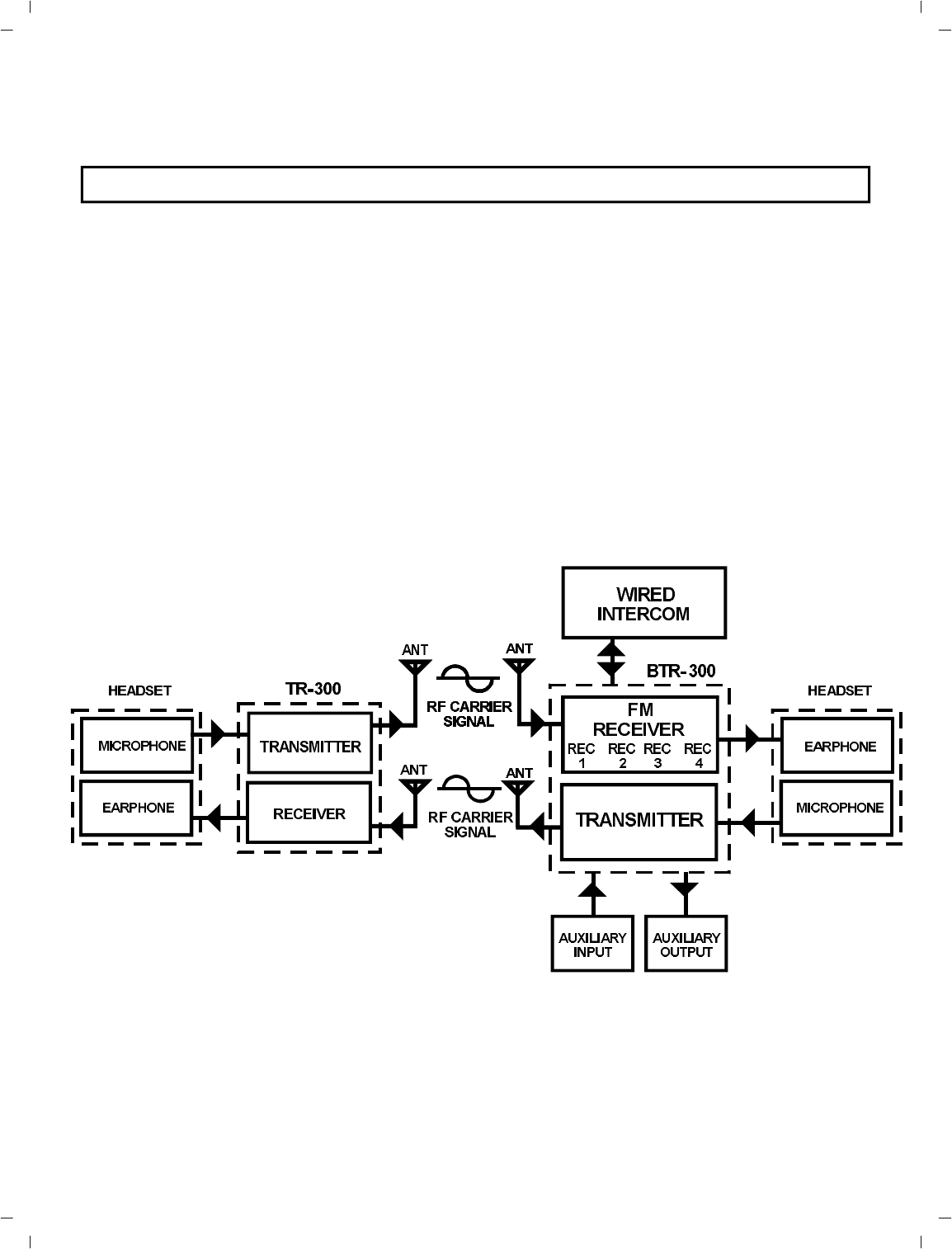
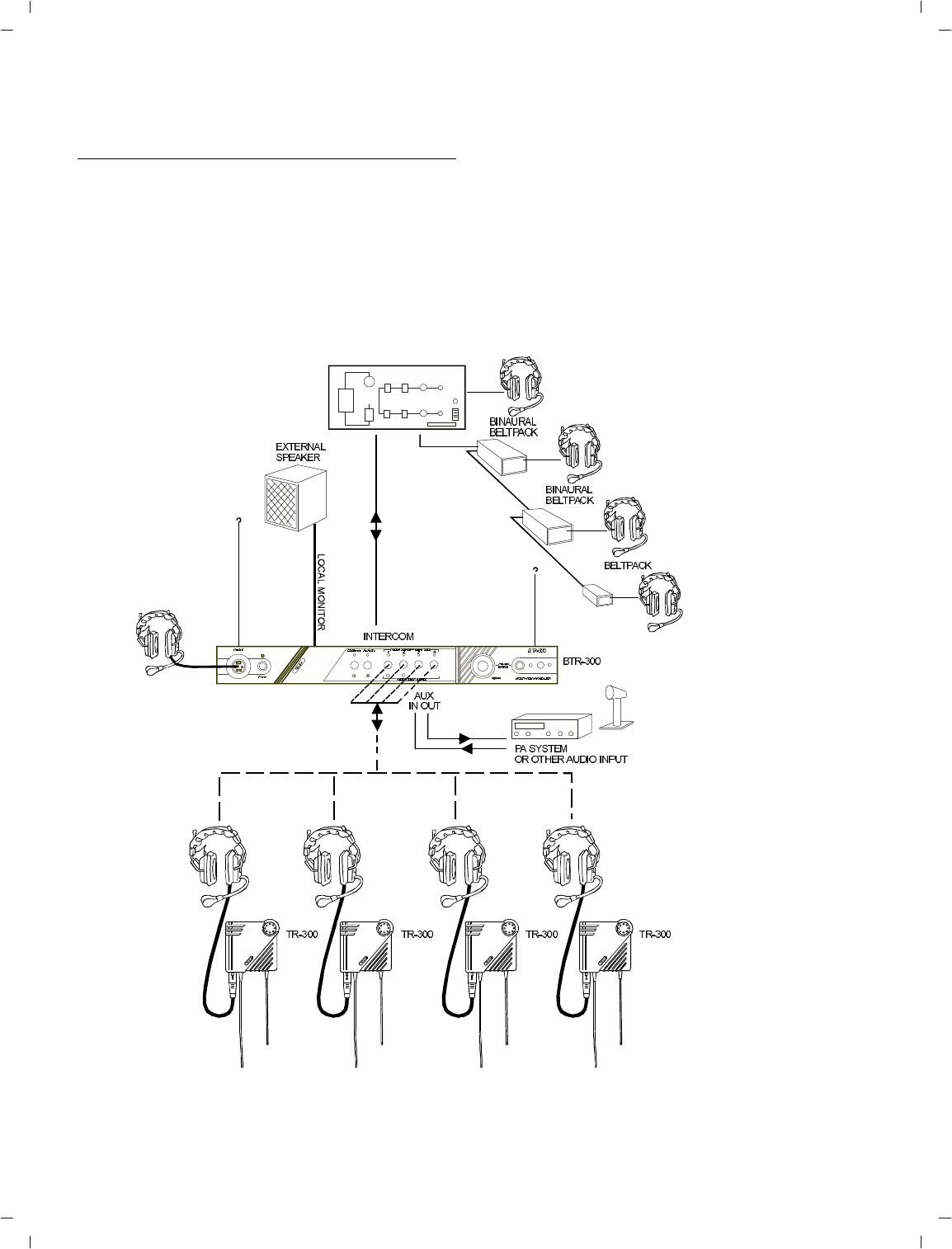
At the BTR-300 op er a tor’s com mand, the
remotes may com mu ni cate with each other,
with a wired in ter com sys tem or with an aux il -
iary sys tem. The BTR-300 Base Sta tion with
its one trans mit and four re ceive chan nels is
de signed to op er ate in full du plex (si mul ta -
neous two-way com mu ni ca tions) with up to
four TR-300 Belt Pack trans ceiv ers. See block
di a gram in Fig ure 1.
Fig ure 1
Block Di a gram of Sys tem
-1-

The sys tem op er ates on se lected fre quen cies
within the 150-216 MHz band.
The BTR-300 sys tem is fully com pat i ble with a
num ber of other wired in ter com man u fac tur ers
units. See the BTR-300 Setup Sec tion for ad di -
tional in for ma tion.
The TR-300 Trans ceiver op er ates in the con tin -
u ous trans mit mode with the au dio ac ti vated by
a switch. As many as four TR-300 belt-pack
trans ceiv ers can op er ate in a fully du plex net -
work with one Telex Model BTR-300 Base
Sta tion.
The TR-300P Trans ceiver op er ates in the
Push-to-transmit mode (the trans mit and talk
func tion are ac ti vated to gether). Any num ber
of TR-300P trans ceiv ers can be used in a
half-duplex net work with one BTR-300 Base
Sta tion. Op er ate only one TR-300P at a time.
At tempting to use two trans mit ters si mul ta -
neously on the same chan nel will cause in ter -
fer ence.
-2-

BTR-300 BASE STATION TRANS CEIVER
TECH NI CAL IN FOR MA TION
-3-
SPEC I FI CA TIONS BTR-300
Over all
In put Power....................................................................... 13.0 VAC RMS/600 mA with sup plied adap tor
or fil tered 12 to 14 VDC/600 mA source.
In ter com Out put .........50 mV (Low) or 330 mV (Hi) RMS into 300 ohm load typ i cal (at rated de vi a tion)
In ter com In put (Gain Min i mum)............................................. 300 mV RMS typ i cal (for rated de vi a tion)
Aux il iary Out put ...........................................430 mV RMS into 600 ohm load typ i cal (at rated de vi a tion)
Aux il iary In put (Gain Max i mum)............................................. 60 mV RMS typ i cal (for rated de vi a tion)
Lo cal Head set In put........................................................................................... 2 mV RMS in put nom i nal
1.5 mV RMS in put at com pres sion (Dy namic)
Lo cal Head set Out put................................................................. 32 mW max i mum out put into 600 ohmst
Tem per a ture Range....................................................................................... -4°F to 130°F (-20°C to 55°C)
Di men sions....................................................................................................15.75" W x 1.75" H x 10.5" D
(40 cm x 4.5 cm x 26 cm)
Weight....................................................................................................................................... 4.5 lbs (2 kg)
Trans mit
RF Fre quency Range............................................................................................................. 150-216 MHz
RF Fre quency Sta bil ity.................................................................................... Crys tal Con trolled, 0.005%
RF Power Out put................................................................................................... ............. 50 mW Typ i cal
Mod u la tion................................................................................................... ............. FM, 3 KHz de vi a tion.
115 mi cro-seconds Pre-emphasis
Trasmit An tenna................................................................................................... ........ 5/8-wave (sup plied)
SO239 con nec tor on chas sis
Mod u la tion Lim iter................................................................................................... .... In ter nal Com pres sor
Mod u la tion Fre quency Range...................................................................................300 to 5000 Hz ±2 dB
Ra di ated Har monics and Spu ri ous Emis sions................................................................................. -45 dBC,
Ex ceeds FCC Spec i fi ca tions
FCC ................................................................................................ Type Ac cepted Un der Parts 90 and 74

FEA TURES
The Telex Model BTR-300 is a Base Sta tion
with one trans mit ter and four re ceiv ers. It is de -
signed for por ta ble two way com mu ni ca tion
with the ca pa bil ity for in ter face to other au dio
sys tems. Fea tures in clude:
•An ex tremely flex i ble unit that has the ca -
pa bil ity to com mu ni cate at one time with
any num ber of the avail able por ta ble sta -
tions (up to four) or wired sta tions (in ter -
com and/or other au dio source).
•Powered by an ex ter nal AC sup ply via the
power jack on the rear of the unit. It can
also be pow ered by any fil tered 12 to 14
VDC/600 mA source or 13.0 VAC RMS
600 mA source.
•In ter com con nec tions with the abil ity to in -
ter face with most wired in ter com sys tems.
•RF LED in di ca tor for each por ta ble sta tion.
•All metal case for su pe rior shield ing.
•Ta ble or rack mount able.
-4-
SPEC I FI CA TIONS BTR-300 (CONT.)
Re ceive
RF Fre quency Range............................................................................................................... 150-216 MHz
RF Fre quency Sta bil ity......................................................................................Crys tal Con trolled, 0.005%
Type................................................................................................. Dual Con ver sion super het ero dyne, FM
RF Sen si tiv ity...................................................................................... Less than 0.5 µV for 12 dB SINAD
IF Se lec tiv ity............................................................................. 3 dB at 30 kHz (4 pole Monolythic Fil ter)
Im age Re jec tion................................................................................................... ................ 65 dB or better
Squelch Quieting.................................................................................................................................. 90 dB
Squelch Thresh old............................................................................................................ 1.0 µV (In ter nal)
Sig nal-to-Noise Ra tio........................................................................................................................... 90 dB
Re ceive An tenna.......................................................................................................... 5/8-wave (sup plied)
SO239 con nec tor on chas sis
Dis tor tion................................................................................................... .. Less than 1% at Rated Out put
CON TROLS and CON NEC TIONS
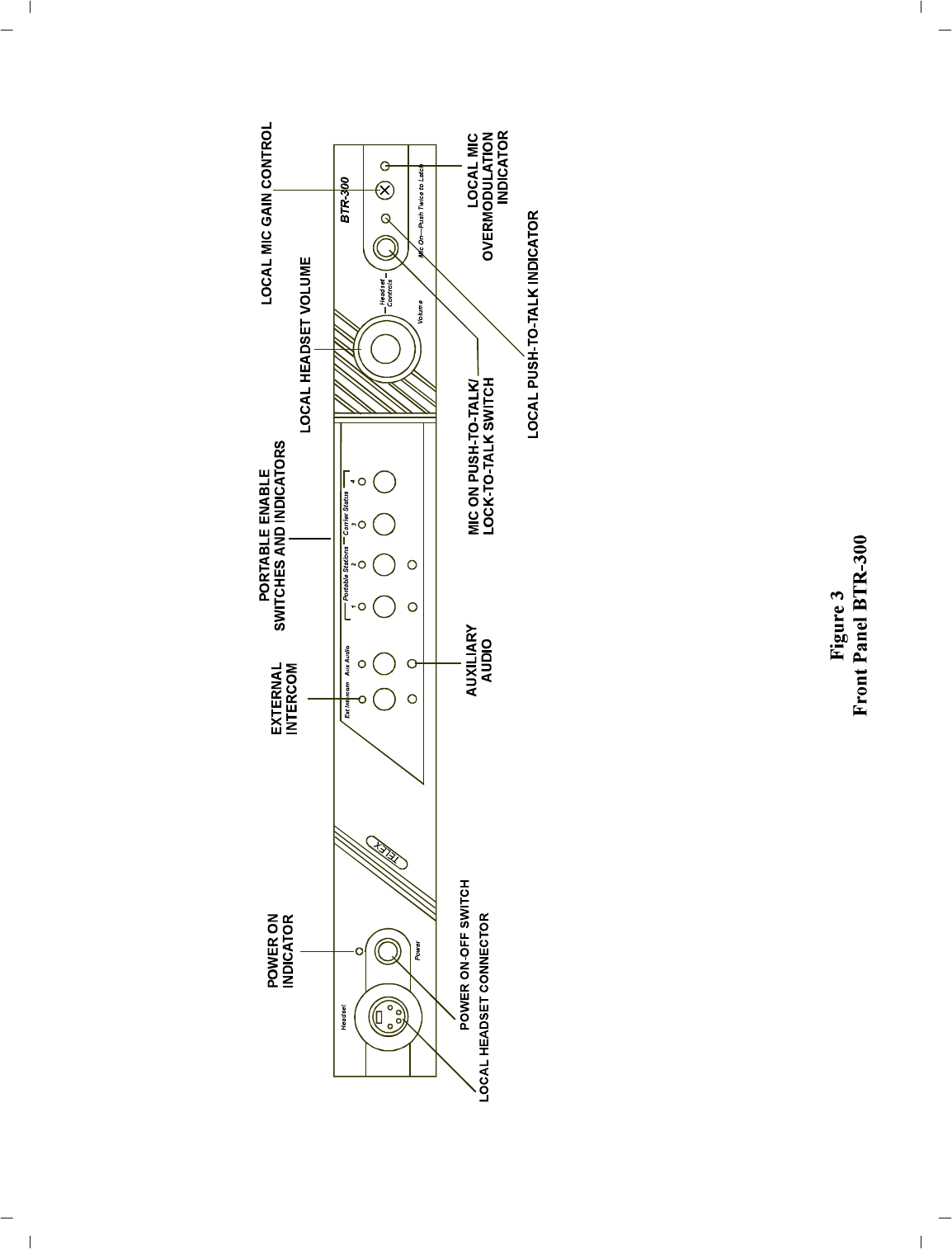
FRONT PANEL ( Re fer to Fig ure 3)
Power ON/OFF Switch:Push this switch once
to turn power ON; push it again to turn the
power OFF.
Power ON In di ca tor: The Power ON In di ca -
tor is il lu mi nated when the Power ON/OFF
Switch is pushed in the ON Po si tion.
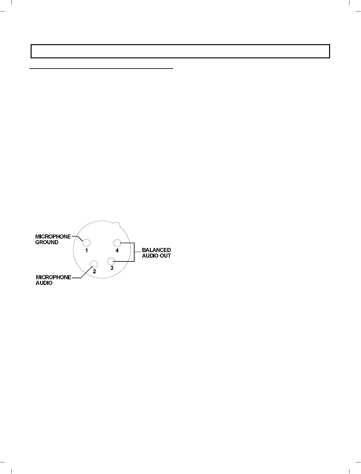
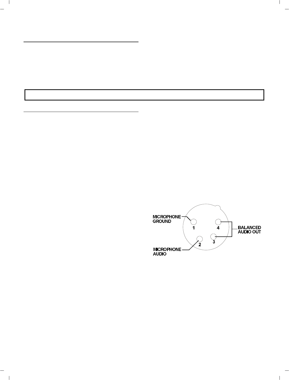
Lo cal Head set Con nec tor: 4 Pin XLR Con -
nec tor for In put/Out put. The head set jack will
ac cept many Telex model head sets. Com pat i ble
with other in ter com head sets with four pin
XLR con nec tors that are wired as shown in
Fig ure 2.
Fig ure 2
Head set XLR Con nec tor Wiring
Lo cal Head set Vol ume: Ad justs vol ume to
Lo cal Head set.DOES NOT AF FECT
MI CRO PHONE GAIN.
Mic On-Push-to-Talk/Lock-to-Talk Switch:
En ables the lo cal head set mi cro phone au dio
func tion.
NOTE: DOES NOT con trol base sta tion RF
trans mit.
Lo cal Push-to-Talk In di ca tor: Will be il lu mi -
nated when ever the talk func tion is on.
Lo cal Mi cro phone Gain Con trol and
Overmodulation In di ca tor: A screw driver
ad just able con trol is pro vided to con trol the in -
put level of the lo cal head set mic. This in put is
pro tected from over loads by means of a gain
com pres sor whose op er a tion is sig naled by the
gain LED in di ca tor.
Por ta ble En able Switches and In di ca tors:
When in the “IN” po si tion, the En able switches
al low the user of the cor re spond ing por ta ble
unit to be heard by oth ers con nected to the sys -
tem. When in the “OUT” po si tion, the re spec -
tive por ta ble will be muted, but this por ta ble
will still be able to hear all other se lected
remotes and in ter faces. The in di ca tors nor -
mally show the pres ence of a por ta ble trans -
ceiver in use on the chan nel cor re spond ing to
that in di ca tor.
-5-

External In ter com Switch, Level Con trol,
and In di ca tor: This switch en ables the wired
in ter com in ter face when “IN”, and dis ables it
when “OUT”. For RTS in ter coms, the “IN” po -
si tion is chan nel A and the “OUT” po si tion is
chan nel B. A screw driver ad just able con trol is
pro vided to con trol the in put level of the wired
in ter com.
Aux il iary Au dio En able Switch, Level Con -
trol, and In di ca tor: The switch en ables and
dis ables the Aux il iary in ter face when “IN” and
“OUT”, re spec tively. The func tion of the level
con trol here is the same as that de scribed for
the in ter com.
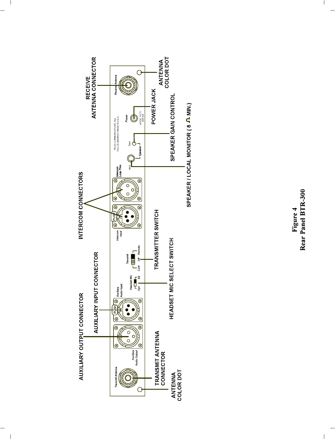
REAR PANEL (Re fer to Fig ure 4)
Trans mit and Re ceive An tenna Con nec tors:
At tach 5/8-wave an tenna s (sup plied) to these
con nec tors. An tenna color should match the
“color dot.”
Trans mit Switch: Slide switch that al lows the
op er a tor to se lect one of three trans mit modes.
In the “OFF” po si tion, the trans mit ter is al ways
off. This mode may be used if the base is func -
tion ing solely as a mon i tor. In the “CONT” po -
si tion, the trans mit ter is al ways on. This
con tin u ous mode is rec om mended over the
“RE MOTE” mode. In the “RE MOTE” po si -
tion, the trans mit ter is en abled only when one
or more portables are ac tive.
Head set Mi cro phone Se lect Switch:This
switch al lows the user to se lect ei ther an
Electret or Dy namic mi cro phone.
In ter com Con nec tors: Con nec tions to in ter -
face the BTR-300 with a wired in ter com sys -
tem.
Aux il iary Out put/In put Con nec tors: Can be
used for 2-way (four wire) in put and out put to
the BTR-300 or as a sim plex in put or out put.
Typ i cal uses are 4 wire low level in ter com’s,
tape re cord ers, pub lic ad dress in puts or out -
puts, or when op er at ing two BTR-300 units si -
mul ta neously.
Power Jack: For ex ter nal AC sup ply adap tor
(sup plied) or any fil tered 12 to 14 VDC/600
mA source, or 13.0 VAC RMS/600 mA source.
Speaker Jack: Al lows the user to con nect an
ex ter nal speaker (8 ohms min i mum) to the unit.
Speaker Gain Con trol: Screw driver ad just -
able. Ad just the gain con trol clock wise to in -
crease speaker gain or coun ter clock wise to
de crease speaker gain.
NOTE: Leave set ting coun ter clock wise if no
speaker is at tached.
-6-
-7-
-8-

TR-300 BELT-PACK TRANS CEIVER
TECH NI CAL IN FOR MA TION
-9-
SPEC I FI CA TIONS TR-300
Over all
Power Re quire ments................................................................... 6 AA cells (Al ka line, NEDA, MN 1500)
Nickel-Metal Hydride Op tional
Cur rent Drain................................................................................................... ..................... typ i cal 65 mA
Tem per a ture Range..................................................................................... -4 oF to 130oF (-20 oC to 55 oC)
Di men sions.................................................................................................... 4.25" W x 4.125" H x 2.0" D
(108mm x 105mm x 51mm)
Weight................................................................................................................ 13oz (369g) with bat ter ies
Trans mit An tenna................................................................................................. 1/4-wave wire (at tached)
Re ceive An tenna.................................................................................................. 1/4-wave wire (at tached)
Trans mit
RF Fre quency Range................................................................................................... .......... 150-216 MHz
RF Fre quency Sta bil ity.................................................................................... Crys tal Con trolled, 0.005%
RF Power Out put................................................................................................................ 50 mW Typ i cal
Mod u la tion............................................................................................................ FM, 5000 Hz de vi a tion,
115 mi cro-seconds Pre-emphasis
Mod u la tion Lim iter..................................................................................................... In ter nal Com pres sor
Mod u la tion Fre quency Range ............................................................................... 300 to 5000 Hz +/-2dB
Mi cro phone Au dio In put................................................................................................... 30 to 3500 ohms
Mi cro phone In put Sen si tiv ity..................................................................... 2 mV Dy namic, 4 mV Electret
Ra di ated Har monics and Spu ri ous Emis sions............................................................................... -45 dBC,
Ex ceeds FCC Spec i fi ca tions
FCC ................................................................................................ Type Ac cepted Un der Parts 90 and 74
Re ceive
RF Fre quency Range................................................................................................... .......... 150-216 MHz
RF Fre quency Stabiltiy............................................................................ Crys tal Con trolled, 0.005%Type
Dual Conversion Superheterodyne, FM
RF Sen si tiv ity...................................................................................... Less than 0.5 µV for 12 dB SINAD
IF Se lec tiv ity............................................................................................. 3 dB at 30 kHz (Ce ramic Fil ter)
Im age Re jec tion................................................................................................................... 70 dB or better
Squelch Quieting................................................................................................... ............................... 90 dB
Squelch Thresh old............................................................................................................. 3.0 µV (In ter nal)
Sig nal-to-Noise Ra tio................................................................................................... ........................ 90 dB
Au dio Out put........................................................................................... 32 mW into 600 ohms (Head set)
Dis tor tion..................................................................................................... Less than 1% at Rated Out put
FEA TURES
•Light weight, small size and i s self-contained.
•2 sep a rate an ten nas, one for trans mit, the
other for re ceive.
•Push-to-Talk with Lock-to-Talk fea ture
switch for the TR-300 and Push-to-Transmit
with Lock-to-Transmit fea ture for the
TR-300P.
CON TROLS AND CON NEC TIONS
EX TER NAL CON TROLS (Re fer to Fig ure 6)
Vol ume OFF/ON Con trol: This thumbwheel
con trol serves as both an off/on switch and as a
vol ume con trol.
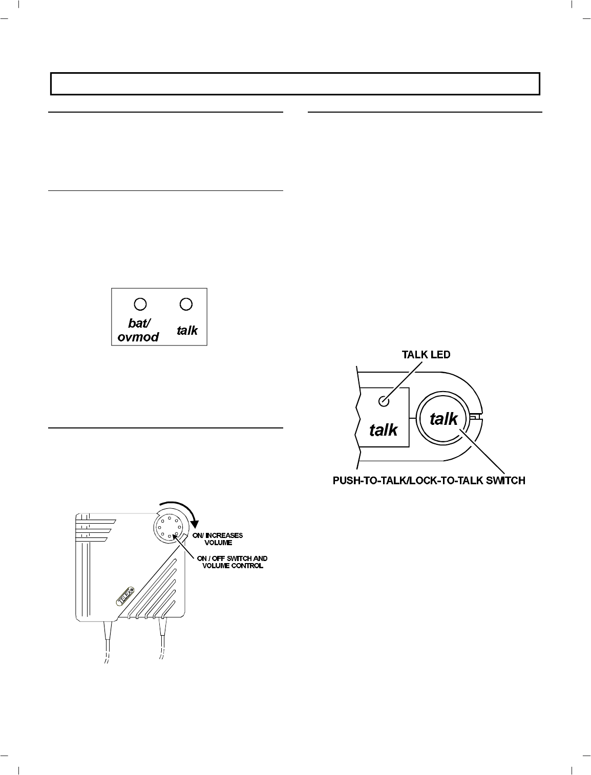
Low Bat tery and Overmodulation
In di ca tor LED:
Low Bat tery In di ca tor : Part of the bat tery
check cir cuit. When the power switch is
placed in the “ON” po si tion the LED will
flash one time if the bat tery is good. A poor
bat tery will cause the LED to il lu mi nate con -
tin u ously and a bad or un us able bat tery will
not cause any il lu mi na tion at all.
Overmodulation In di ca tor: Uses the same
LED as the low bat tery in di ca tor. Dur ing the
talk mode, if the mi cro phone gain is too
high, the LED will il lu mi nate when talk ing.
Push-To-Talk/Lock-To-TalkSwitch: For
Model TR-300, this switch en ables the talk
func tion. For Model TR-300P, this switch en -
ables the trans mit and au dio func tion and oth -
er wise op er ates as de scribed for BTR-300.
Talk LED In di ca tor: (La beled “talk”) Will be
il lu mi nated when ever the talk func tion on the
TR-300 or trans mit func tion on the TR-300P is
en abled.
Head set Jack: A four pin XLR con nec tor for
In put/Out put. The head set jack will ac cept
many dif fer ent Telex model head sets. Com pat i -
ble with other in ter com head sets with four pin
XLR con nec tors that are wired as shown in
Fig ure 5.
Charge Jack: Al lows nickle-metal hy dride
bat ter ies to be charged with out re mov ing them
from the unit.
Fig ure 5
Head set XLR Con nec tor Wiring
-10 -
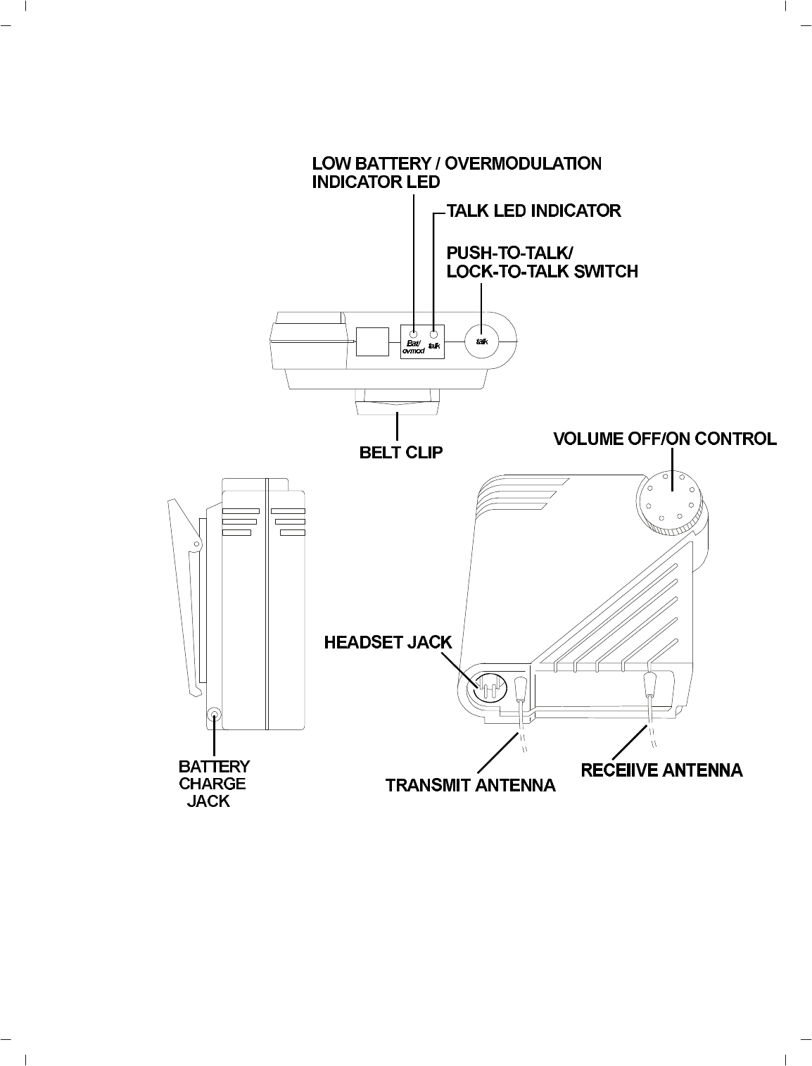
Fig ure 6
Ex ter nal Con trols, TR-300
-11 -
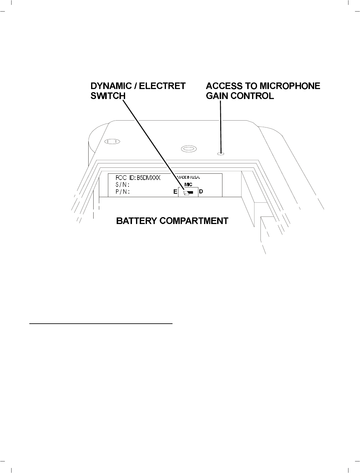
Fig ure 7
In ter nal Con trols, TR-300
IN TER NAL CON TROLS (Re fer To Fig ure 7)
Mi cro phone Gain Con trol: Screw driver ad -
just able by re mov ing belt clip and pry ing out
the small rub ber plug to the right of the screw
boss.
Dy namic/Electret Switch: This switch al lows
se lec tion of “D” when us ing a Dy namic Mi cro -
phone or "E" when us ing an Electret Mi cro -
phone.
Bat tery Com part ment: Holds 6 AA bat ter ies
in a re mov able bat tery holder (sup plied).
-12 -
EQUIP MENT SET-UP
UN PACKING
Un pack your BTR-300 and TR-300 Sys tem. If
there are any dam ages or short ages, re fer to the
“War ranty Ser vice In for ma tion" sec tion in this
man ual.
AN TENNA IN FOR MA TION
AN TENNA CON NEC TIONS
The BTR-300 is sup plied with two (2) an ten -
nas. One 5/8-wave an tenna for Trans mit and
one 5/8-wave for Re ceive.
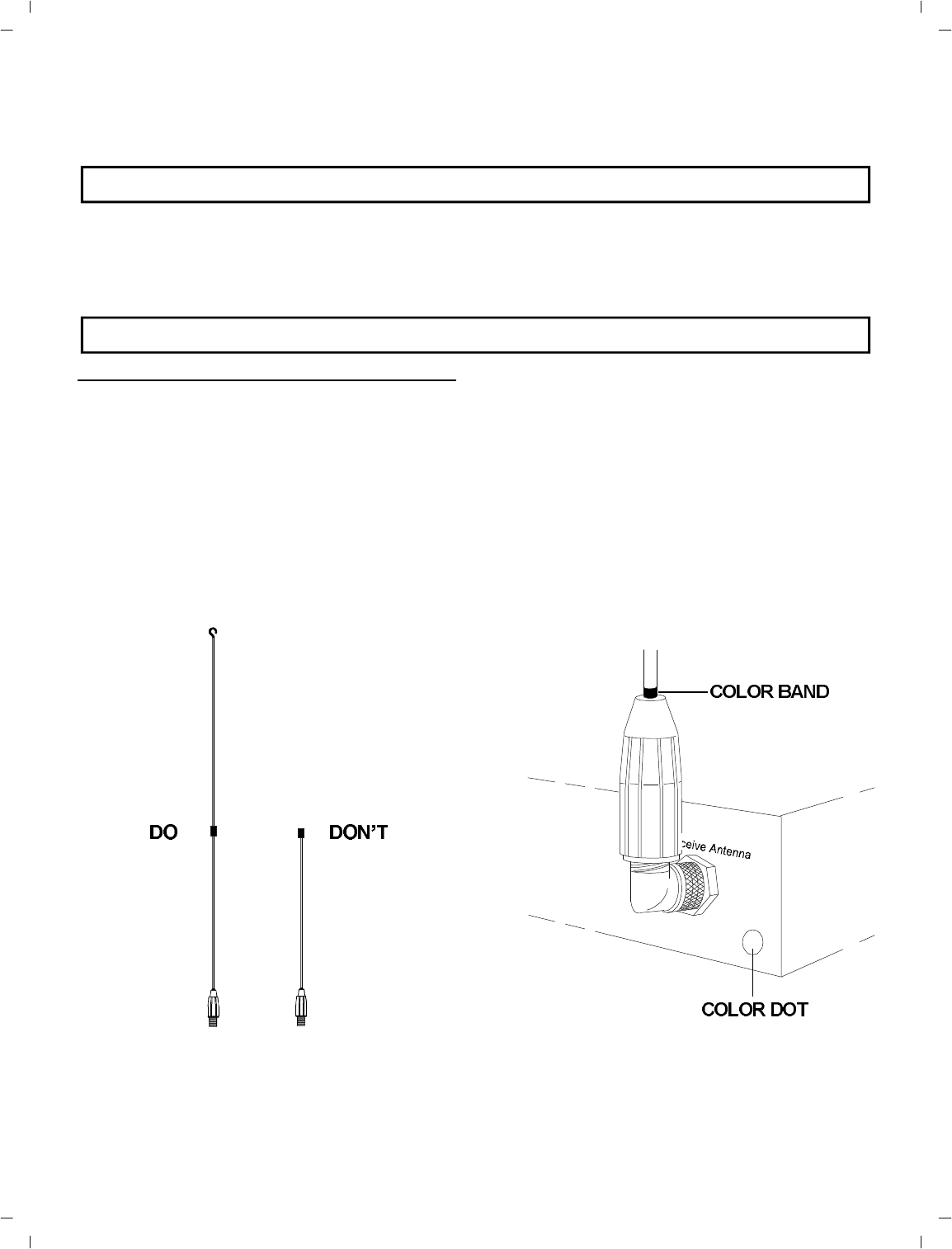
As sem ble the 5/8-wave an tenna by screw ing
the two sec tions together as shown in Fig ure 8.
Both sec tions of the BTR-300 5/8-wave an ten -
nas must be used. Leaving off the top sec tion
will re sult in re duced dis tance ca pa bil ity.
Fig ure 8
5/8-wave An tenna As sem bly
To in sure that the fre quency range of the an ten -
nas match the re ceiver and trans mit ter of the
BTR-300, match the color band on the an tenna
with the color dot on the BTR-300.
At tach the an ten nas to the an tenna in put re cep -
ta cles. Tighten the con nec tor se curely.
Fig ure 9
Attaching 5/8-wave An tenna
-13 -
AN TENNA PO LAR IZA TION
The Telex Wire less In ter com Sys tem is “Ver ti -
cally Po lar ized". This means both the trans mit -
ting and re ceiv ing an ten nas should op er ate in
the ver ti cal po si tion.
Fig ure 10
Ver ti cally Po lar ized An tennas
The an ten nas can be remoted for better sig nal
path. A Telex coax as sem bly is re quired. See
“Ac ces sory” sec tion for or der in for ma tion.
NOTE: If your BTR-300 trans ceiver is to be
lo cated in a shielded rack mount en clo sure or
other poor RF lo ca tion, you must re mote the
5/8-wave an ten nas with coax as sem blies.
AN TENNA PLACE MENT
Proper an tenna place ment prob a bly has the
most ef fect on your TELEX Wire less In ter com
Sys tem’s over all per for mance. The fol low ing
sug ges tions will re sult in op ti mum per for -
mance.
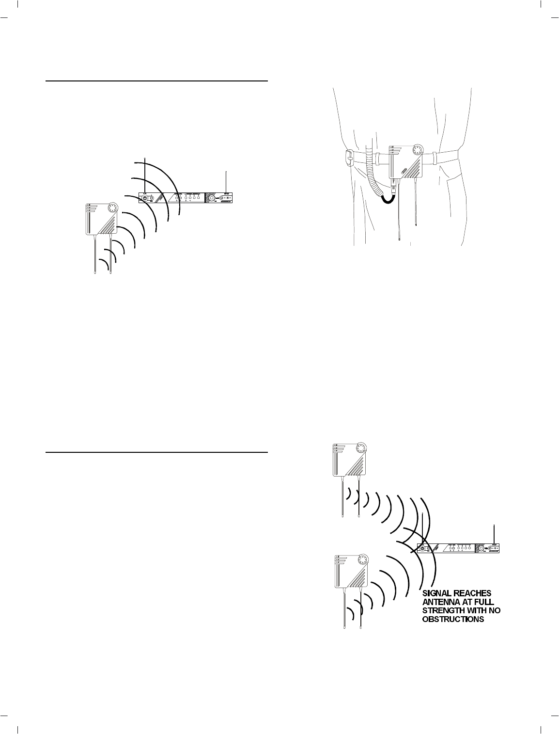
Proper place ment of the TR-300 can be crit i cal.
The trail ing an ten nas should “dan gle” freely.
“Wadding” the an ten nas up and plac ing them
in a pocket, etc., will re duce sys tem dis tance.
It is sug gested that the unit be worn on the belt
or pocket with both an tenna’s hung ver ti cally
for best op er at ing range and per for mance.
Fig ure 11
Proper Dress ing of the An tennas
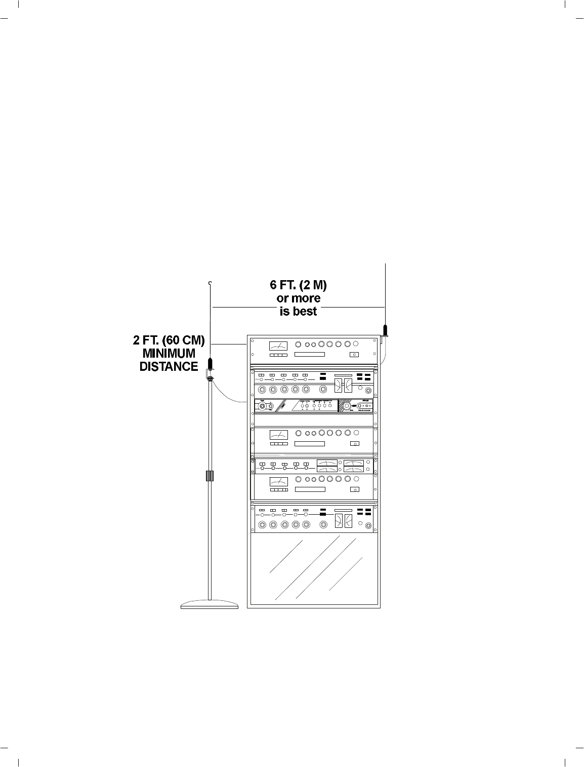
Keep the dis tance be tween the base (BTR-300)
and the belt packs (TR-300) an ten nas as short
as pos si ble. The greater the dis tance, the
weaker the sig nal. How ever, the portables
should be a min i mum dis tance of 10 feet from
the base sta tion and each other for best per for -
mance.
Make sure the “sig nal paths” be tween the
BTR-300 and remotes are un ob structed. You
should al ways be able to vis i bly lo cate the an -
ten nas for best per for mance.
Fig ure 12
Keeping Site Clear to An tenna
-14 -
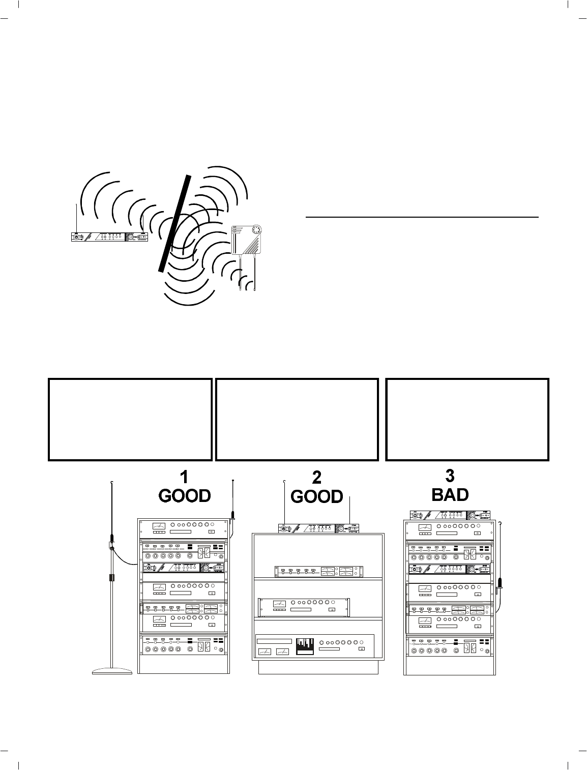
At tempting to op er ate the wire less in ter com
sys tem through or around walls, ceil ings, metal
ob jects, etc. will re duce sys tem range and per -
for mance.
SIG NAL RE FLEC TION OFF A METAL OB STRUC TION
CAUSES RE DUCED SIG NAL AND “MULTIPATH”
Fig ure 13
Op er ating Sys tem Near Ob struc tions
DO NOT- mount the BTR-300 5/8-wave an -
ten nas next to metal such as beams, walls with
metal studs, equip ment racks, etc. This also
ap plies to the an ten nas when as sem bled di -
rectly to the BTR-300. This will “de tune” the
re ceiv ing an tenna which can re sult in noise or
loss of RF sig nal at the BTR-300. See Fig ure
14.
IM PROVING RE CEP TION AND
IN CREASING RANGE
Keeping the dis tance from the base (BTR-300)
and the belt packs (TR-300) as short , and un -
ob structed as pos si ble will pro duce the most re -
li able per for mance.
The BTR-300 is sup plied with two an ten nas.
This should pro vide sat is fac tory sys tem per for -
mance in most ap pli ca tions. Sys tem range can
be en hanced by remoting the 5/8-wave re ceive
an tenna us ing the avail able ac ces so ries.
-15 -
1. Placing the unit in an
equip ment rack and
remoting the an ten nas
is GOOD.
2. Placing the unit ontop of
a shelf or equip ment
rack un ob structed with -
out remoting the an -
tenna is GOOD.
3. Placing the unit in an
equip ment rack with the
an ten nas mounted on
the BTR-300 or the side
of the rack is BAD.
Fig ure 14
BTR-300 An tenna Place ment
BTR-300 SET-UP
LO CA TION
Locate the BTR-300 trans ceiver on a level sur -
face with the rear of the unit fac ing you. See
“An tenna In for ma tion” sec tion for more in for -
ma tion on choos ing a lo ca tion.
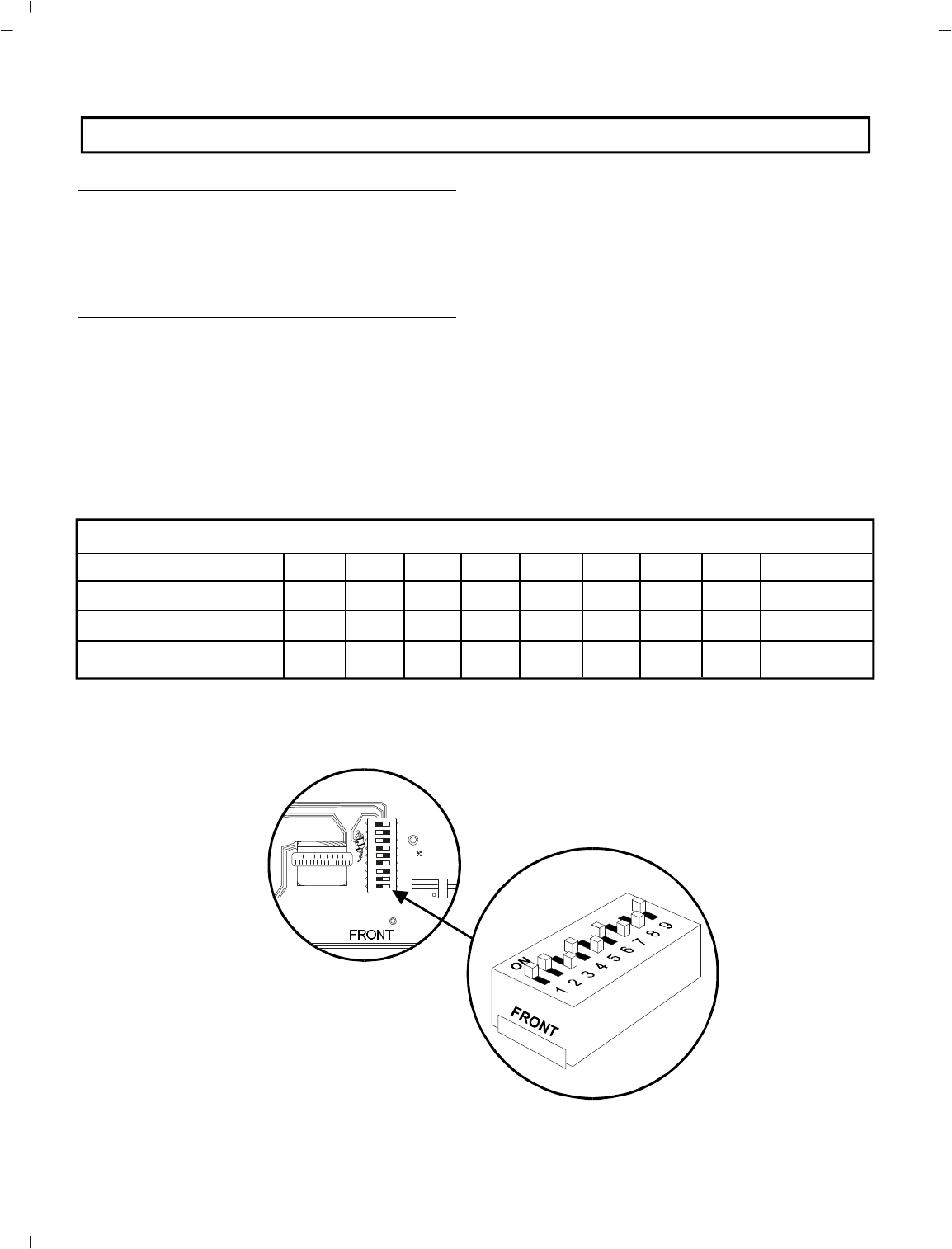
IN TER NAL IN TER COM SWITCHES
In ter com Dip Switch: Lo cated in the in side of
the unit is a DIP Switch. This switch will have
to be set for the wired in ter com unit you will
be us ing. The switch is fac tory set for in ter fac -
ing with Telex Audiocom wired in ter com
units. See Ta ble 1 if you will be us ing an RTS
or Clearcom wired in ter com sys tem.
To change the switch po si tions you will need to
re move the cover on the BTR-300. Re move
three #6-32 x 3/8" screws on both sides of the
unit. Re move four #4-40 x 3/16" screws on the
top front and loosen three #4-40 x 3/16" screws
on the back of the unit. The cover will lift off.
Ref er ence Fig ure 15 for switch po si tions.
Change the switch po si tions as in di cated in the
chart de pend ing on the wired in ter com sys tem
you will be us ing. Af ter set ting this switch, set
the High/Low switch as shown in the next sec -
tion and then re place cover and se cure with the
hard ware pre vi ously re moved.
Ta ble 1
Dip Switch Po si tions For Wired In ter com Ter mi na tions
-16 -
Fig ure 15
Dip Switch
SWITCH PO SI TION
1234567 8 9
Telex AudiocomONONOFFONOFFONOFF OFF ON
RTSOFFOFFONOFFONOFFON ON OFF
ClearcomONOFFONONOFFOFFOFF ON ON
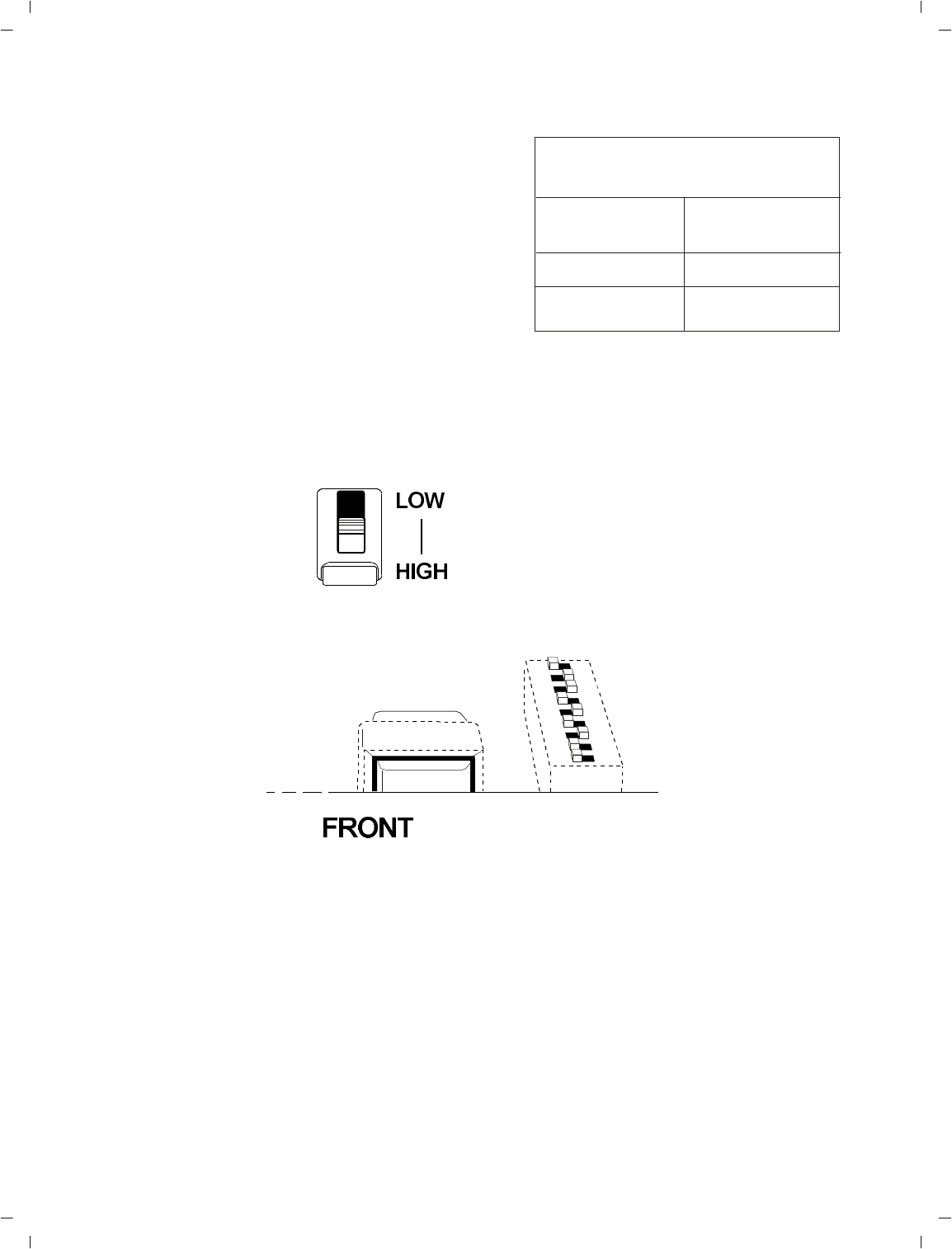
High/ Low Switch: Along with set ting the DIP
switch in side the unit to cor re spond to the
wired in ter com you have se lected to use, you
must also set the “High/Low” switch. This
switch is also lo cated in side the BTR-300 as
shown in Fig ure 16.
For the cor rect set ting cor re spond ing to your
wired in ter com unit see Ta ble 2. The switch is
fac tory set for use with Telex AudioCom or
RTS wired in ter coms.Ta ble 2
Fig ure 16
Lo ca tion of High/Low Switch
-17 -
Switch
Set ting
Telex
AudioComHigh
RTSHigh
ClearcomLow
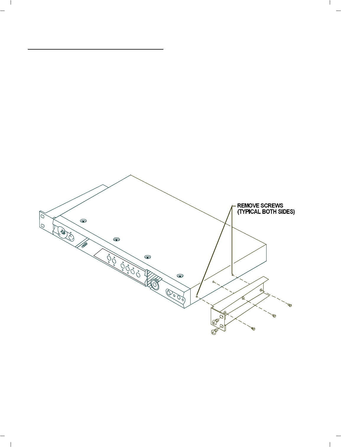
RACK MOUNTING
To rack mount the BTR-300 base trans ceiver
do the fol low ing:
Re move the front two #6-32 x 3/8" screws on
each side of the trans ceiver as shown in Fig ure
17.
Place the rack mount brack ets (sup plied) on ei -
ther side of the unit and in sert three #6-32 x
3/8" screws for each bracket. Tighten the
screws se curely.
In sert the BTR-300 into your 19" rack en clo -
sure and in sert four (4) #10-32 x 3/8" Phil lips
pan head screws (sup plied) in each cor ner of
the rack mount brack ets and se cure to your en -
clo sure.
Fig ure 17
Attaching Brackets For Rack Mount ing
-18 -
Remoting An tennas: It will be nec es sary to
re mote both the trans mit and re ceive an ten nas
on the BTR-300 when it is rack mounted.
Con nect the coax ca ble as sem bly (not sup -
plied), to the back of the re ceive an tenna re cep -
ta cle and re mote the 5/8-wave an tenna. The
an tenna can be at tached to ei ther a wall mount
bracket or a mi cro phone stand bracket (not
sup plied). See “Ac ces sory” sec tion for or der
in for ma tion.
You will also need to re mote the trans mit an -
tenna in the same man ner. Con nect a coax ca -
ble as sem bly to the trans mit an tenna
re cep ta cle. Re mote the 5/8-wave an tenna, by
at tach ing the an tenna to one of the brack ets
(not sup plied).
Fig ure 18
Remoting An tennas when Rack Mounted
-19 -
-20 -
LO CAL HEAD SET CON NEC TION
In sert the head set/mi cro phone into the 4 pin
XLR con nec tor on the front panel. See the mi -
cro phone con nec tion di a gram (Fig ure 2) if
other than a Telex Head set is used.
HEAD SET MI CRO PHONE SE LECT
SWITCH
If the head set you are us ing has an Electret mi -
cro phone, the lo cal mi cro phone se lect switch
must be in the “ELT” po si tion (Electret). This
switch is lo cated on the rear panel. A +5 volt
bias is avail able at the mi cro phone plug for
electret use.
If you are us ing a head set with a dy namic mi -
cro phone, place the lo cal mi cro phone se lect
switch in the “DYN” po si tion (Dy namic).
NOTE: FOR PROPER OP ER A TION YOU
MUST MATCH THE TYPE OF MI CRO -
PHONE YOU ARE USING WITH THE DY -
NAMIC/ELECTRET SWITCH LO CATED
ON THE REAR OF THE UNIT.
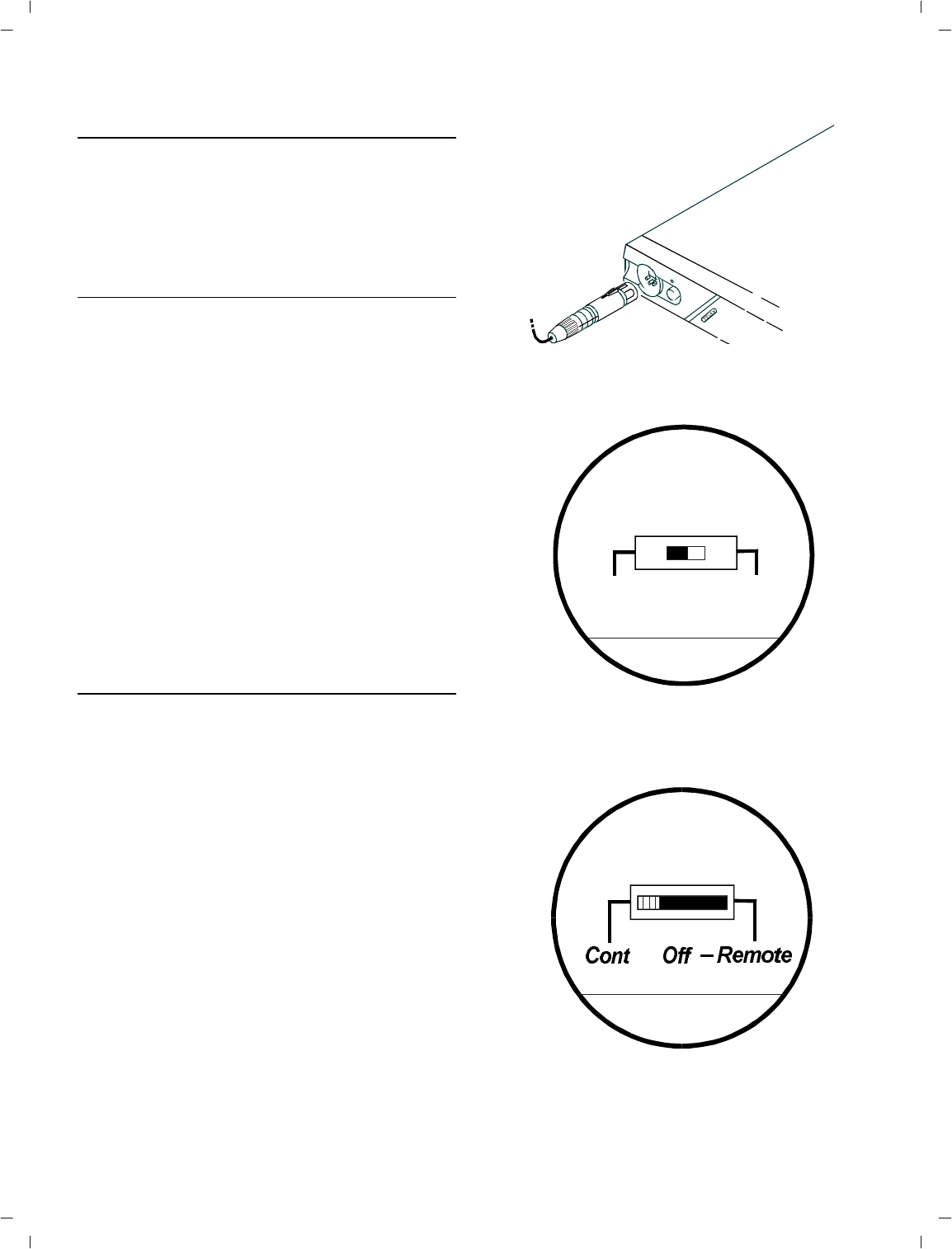
TRANS MIT SWITCH
Al lows the op er a tor to se lect three dif fer ent
types of trans mit ting modes; con tin u ous trans -
mit ter, trans mit ter off, or re mote trans mit ter.
For most op er a tions, place the trans mit ter
switch in the “CONT” po si tion (Con tin u ous
mode).
In the Con tin u ous mode the trans mit ter will
be on at all times re gard less of whether the
portables are on or not.
In the Re mote mode, the only time the base
can trans mit is when a por ta ble unit is turned
on.
In the Off mode the BTR-300 base sta tion
will not trans mit to the re mote belt-packs.
This mode might be used if the base is to be
a mon i tor sta tion only.
Fig ure 19
Con necting Head set to the BTR-300
Fig ure 20
Head set Mi cro phone Se lect Switch
Fig ure 21
Trans mit Switch
Headset Mic
DynElt
Transmit
IN TER CON NEC TION to a HARD-WIRED
IN TER COM SYS TEM
The RADIOCOM wire less sys tem can be in te -
grated into Telex in ter com sys tems and most
ex ist ing wired in ter com sys tems in clud ing RTS
and Clearcom.
Con nect the in ter com ca ble to the back of the
BTR-300. There are two in ter com con nec tions
on the back of the unit, one be ing a male con -
nec tor, the other a fe male con nec tor, con nected
in par al lel with each other. Ei ther works as an
in put or out put.
Fig ure 22
Typ i cal In ter face to Wired Sys tem
-21 -
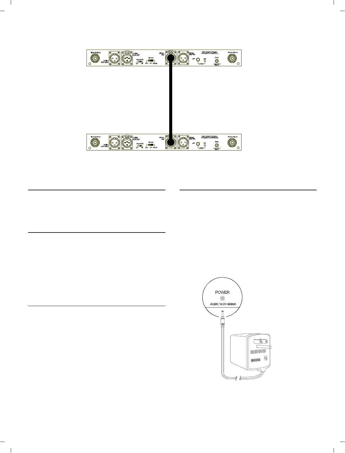
Fig ure 23
Con necting Two BTR-300’s
CONNECTING AUXILIARY AUDIO SYSTEM
Connect the BTR-300 to your aux il iary au dio
via the Aux il iary in put/out put re cep ta cles on
the rear of the unit.
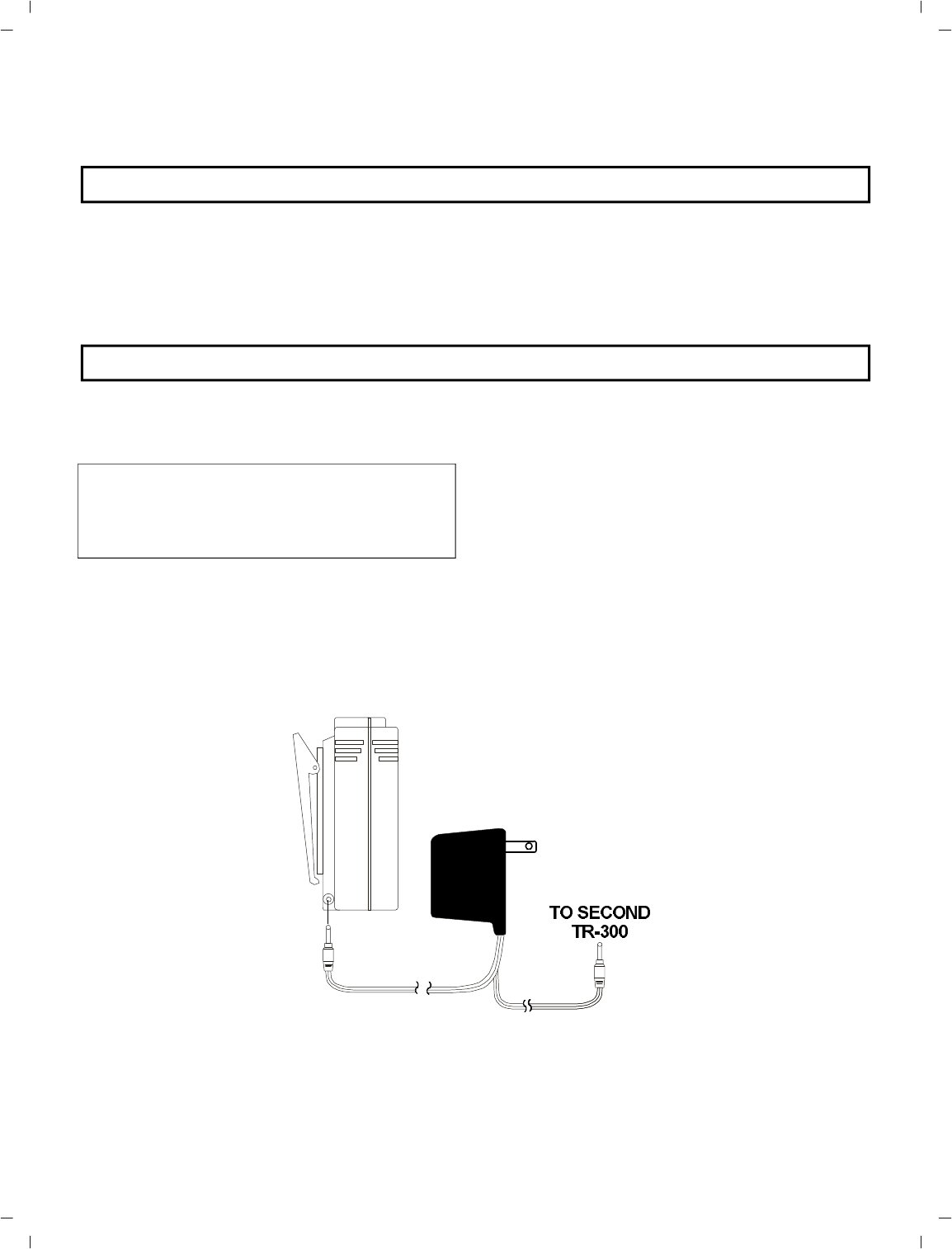
CON NECTING TWO BTR-300’S
Con nect the first BTR-300 to the sec ond
BTR-300 by us ing a short XLR type ca ble (not
sup plied) plugged into ei ther of the in ter com
jacks. See Fig ure 23.
Note that the sta tions need to be on dif fer ent
fre quen cies.
POWER CON NEC TION
In sure the Power ON/OFF Switch on the front
of the BTR-300 is in the “OFF” po si tion. Con -
nect the AC power sup ply cord to the BTR at
the socket la beled “POWER”. Plug the power
sup ply unit into an AC out let.
DUMMY LOAD
In the case where a wired in ter com will not be
used with the BTR-300, it is im por tant that the
dummy load (sup plied) be in stalled. The
dummy load should be plugged into the “In ter -
com Loop-Thru” con nec tor.
NOTE: If the dummy load is not used prop -
erly, an an noy ing squeal may re sult that may
cause dam age to the ears.
Fig ure 24
Con necting the Power Sup ply
-22 -
TR-300 SET-UP
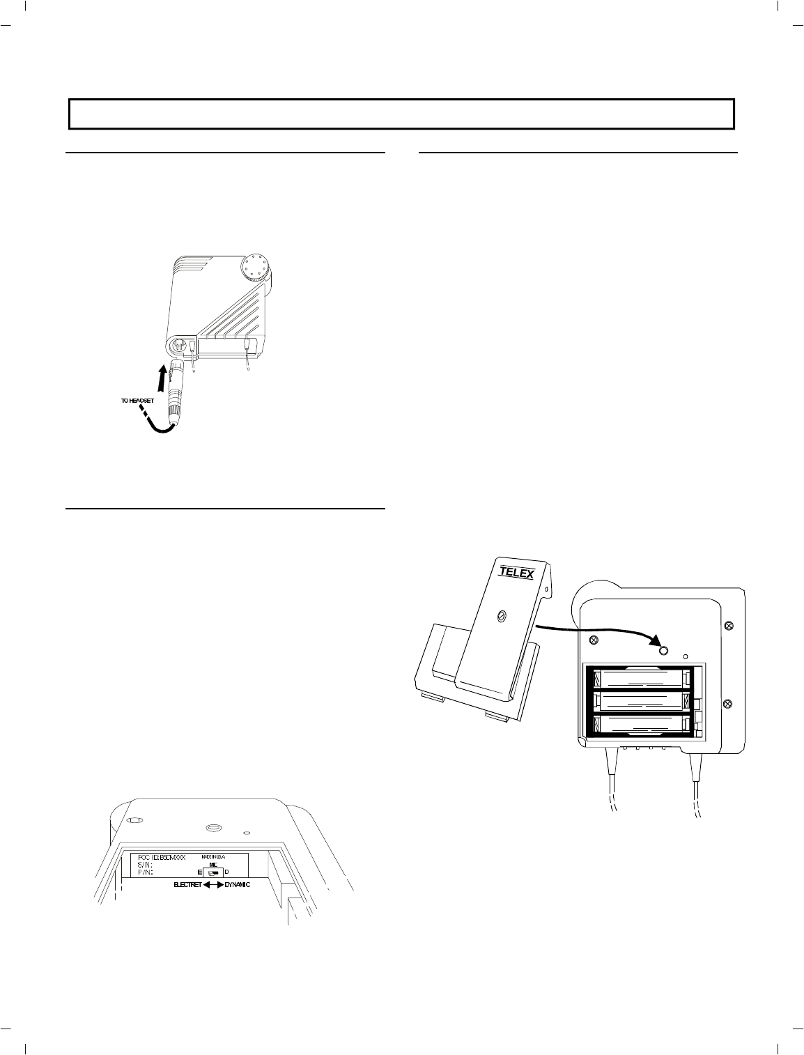
HEAD SET CON NEC TION
In sert the head set/mi cro phone into the con nec -
tor on the bot tom of the unit. See the con nec -
tion di a gram (Fig ure 5) if headsets other than
Telex are used.
Fig ure 25
Con necting Head set
DY NAMIC/ELECTRET SWITCH
If the head set you are us ing has an Electret mi -
cro phone, the dy namic/electret switch must be
in the “E” po si tion . This switch is ac ces si ble by
re mov ing the belt clip and re mov ing the bat tery
holder. A +5 volt bias is avail able at the mi cro -
phone plug for electret use.
If you are us ing a head set with a dy namic mi -
cro phone, place the dy namic/electret switch in
the “D” po si tion.
NOTE: for proper op er a tion you must match
the type of mi cro phone you are us ing with the
dy namic/electret switch lo cated in side the bat -
tery com part ment.
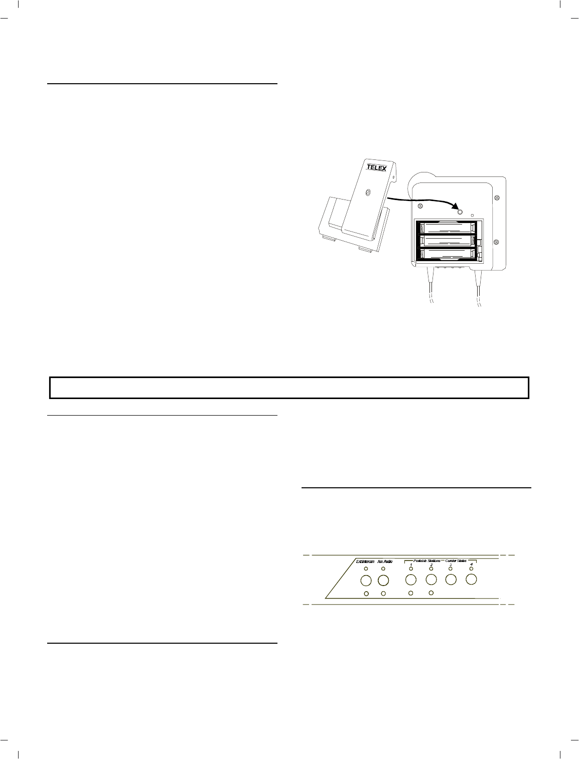
BAT TERY IN STAL LA TION
Insure that the OFF/ON Vol ume con trol knob
is turned OFF. Ac cess the bat tery com part ment
by re mov ing the belt clip on the back of the
unit. Re lease the 1/4 turn fas tener lo cated on
the back of the belt clip and re move belt
clip/cover.
Re move the bat tery holder from the box. In sert
six (6) AA bat ter ies in the holder, pay ing close
at ten tion to po lar i ties of the bat ter ies.It may be
nec es sary to turn the bat ter ies with the thumb
and fore fin ger the first few times the bat ter ies
are in serted into the bat tery holder to in sure
good pos i tive con tact. In sert the holder into the
case and re place the belt clip/bat tery cover and
en gage the 1/4 turn fas tener.
Fig ure 27
Bat tery In stal la tion
-23 -
Fig ure 26
Dy namic/Electret Switch

PRE-WALK-THRU CHECKLIST
Fol low ing the in struc tions fully to this point,
you have suc cess fully com pleted the fol low ing
check list:
Set in ter nal in ter com switch to cor re -
spond with the wired in ter com.
Lo cated the BTR-300 trans ceiver
prop erly.
Con nected power to BTR-300 trans -
ceiver.
Con nected the an ten nas to the
BTR-300 with matched color codes.
Set Dy namic/Electret switches in both
BTR-300 and TR-300
Set trans mit switch on BTR-300.
Con nected head sets to BTR-300 and
all TR-300’s.
Con nected the BTR-300 to any aux il -
iary au dio, in ter com or ex ter nal
speaker.
In stalled bat ter ies in the TR-300 Re -
mote Trans ceiver.
If you missed any of the above in struc tions, go
back and com plete that in struc tion be fore go -
ing on.
-24 -
SYS TEM OP ER A TION
BTR-300 OP ER A TION
POWER
If you have fol lowed the in struc tions un til this
point, you should now be ready to turn both the
TR-300 and the BTR-300 “ON”.
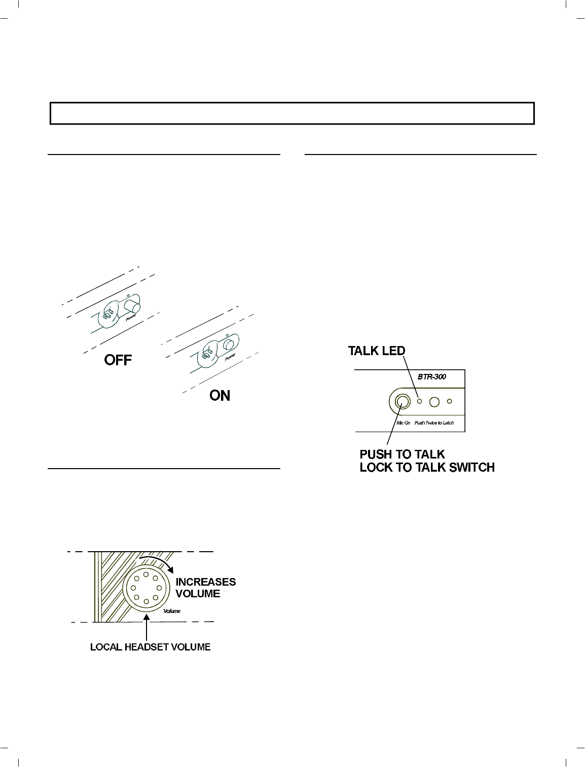
Place the power switch on the BTR-300 in the
“ON” po si tion.The red power on in di ca tor
LED should il lu mi nate.
Fig ure 28
Power ON/OFF - Vol ume Con trol Knob
LO CAL HEAD SET VOL UME
Ad just the vol ume con trol on the BTR-300 by
ro tat ing the Vol ume con trol ei ther clock wise or
coun ter clock wise as re quired for com fort able
lis ten ing vol ume.
Fig ure 29
Vol ume Con trol-BTR-300
PUSH TO TALK/LOCK-TO-TALK
SWITCH
To en able the talk func tion on the BTR-300,
press and hold down on the talk but ton and be -
gin talk ing. Re leasing the talk but ton will dis -
con tinue the mi cro phone au dio. For
con tin u ous talk, quickly press the talk but ton
twice. This en ables the talk func tion as long as
you want. To re lease the talk func tion press the
talk but ton once more and the talk func tion will
cease.
NOTE: The talk LED will be il lu mi nated
when ever the talk func tion is ac ti vated.
Fig ure 30
Push-to-Talk/Lock-to-Talk Switch
-25 -
TR-300 OP ER A TION
POWER
You should now be ready to turn the TR-300
“ON”. Ro tate the OFF/ON Vol ume Con trol
Switch on the TR-300 clock wise to turn the
unit on.
BAT TERY CHECK
As you turn the unit on, note that the bat tery
LED (la beled bat/ovmod) should flash one
time on good bat ter ies. Low bat ter ies will
cause the LED to be il lu mi nated con tin u ously
and a bad bat tery will not cause any il lu mi na -
tion at all.
Fig ure 31
Low Bat tery andOvermodulation
In di ca tor LED
HEAD SET VOL UME
Af ter bat ter ies have been checked, ad just the
vol ume con trol by ro tat ing the con trol as re -
quired for com fort able lis ten ing vol ume.
Fig ure 32
Power ON/OFF - Vol ume Con trol-TR-300
PUSH TO TALK/PUSH TO TRANS MIT
To en able the talk func tion on the Model
TR-300 press and hold down on the talk but ton
and be gin talk ing. Re leasing the talk but ton will
dis con tinue the mi cro phone au dio. For con tin -
u ous talk, quickly press the talk but ton twice.
This locks on the talk func tion. To re lease the
talk func tion press the talk but ton once. Note
that the TR-300 trans mits any time that the
power is on.
For the Model TR-300P, the switch en ables
both the trans mit and au dio func tions and oth -
er wise op er ates as de scribed for the TR-300.
NOTE:The talk LED will be il lu mi nated
when ever the talk func tion is ac ti vated.
Fig ure 33
Push-to-Talk/Lock-to-Talk Switch
-26 -
BAT TERY RE MOVAL
To re move the bat tery holder from the case to
change bat ter ies, fol low the in struc tions as be -
fore for re mov ing the cover. Pull the strap on
the holder, the holder should come out.
NOTE: For max i mum un in ter rupted ser vice it
is sug gested that new 1.5 volt al ka line AA bat -
ter ies be in stalled prior to each use. Avoid
“shelf worn” or “eco nom i cal” bat ter ies. Op er a -
tion from nickle metal hydride bat ter ies is also
per mis si ble. Typ i cal life of fresh al ka line bat -
ter ies with the TR-300 is ap prox i mately 24
hours max i mum, 12-15 hours is typ i cal of fully
charged nickle-metal hy dride bat ter ies.
NOTE: Rechargeable bat ter ies can be charged
right in the TR-300 us ing the Telex AC-1NM
Bat tery Charger. Re fer to “Bat tery In for ma -
tion” Sec tion. Re charge able bat ter ies in the
holder can be charged us ing the Telex
BC-4NM charger.
Fig ure 34
Bat tery Re moval
EN ABLING AU DIO
POR TA BLE TRANS CEIVERS
Se lect the TR-300 portables that will be used
with the BTR-300. Push in the por ta ble en able
switches that cor re spond to the fre quen cies of
the TR-300 remotes that you will be us ing. The
fre quen cies of the por ta ble sta tions 1,2,3, and
4, are listed on the bot tom of the BTR-300. The
Por ta ble Car rier LED will il lu mi nate when the
re mote on that fre quency is turned on. The in -
di ca tors may also light in re sponse to out side
in ter fer ence on that chan nel or to
intermodulation aris ing from portables be ing
used at too close a dis tance to the base. To pre -
vent these sources from cre at ing un de sir able
noise, all un used chan nels should be switched
out.
IN TER COM SWITCH
The in ter com switch in the front of the unit will
act as an en abling switch when the unit is be ing
used with ei ther a Telex Audiocom wired in ter -
com or Clearcom wired in ter com.
When us ing a RTS sys tem wired in ter com the
switch will act as a chan nel se lec tor switch for
se lect ing of ei ther Chan nel A or Chan nel B.
AUX IL IARY
The AUX Switch on the front of the BTR-300
will en able any aux il iary au dio that is used.
-27 -
Fig ure 35
En able Switches
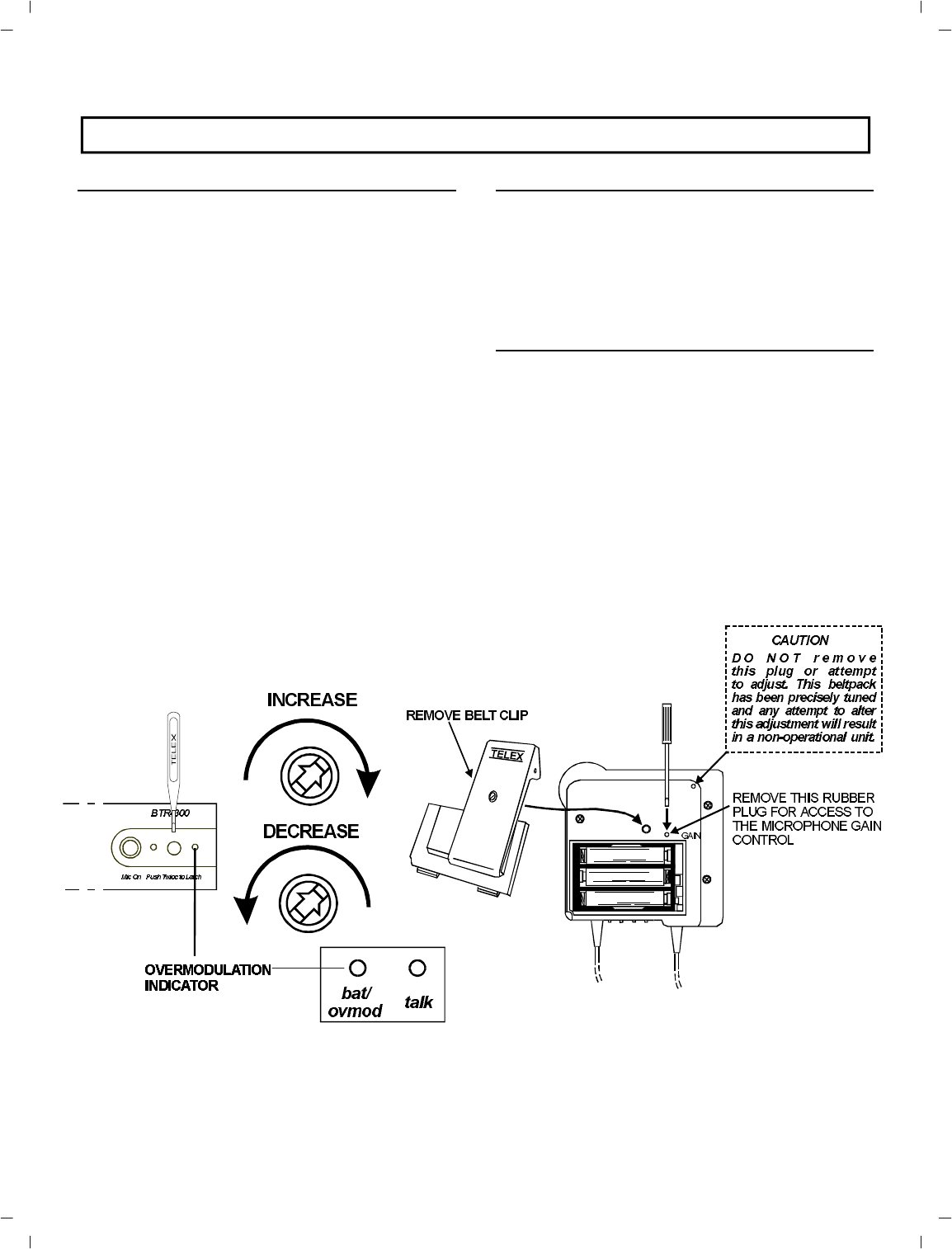
SETTING SYS TEM GAIN LEVELS
AD JUSTING GAIN
The gain may need to be ad justed for var i ous
au dio con di tions. The overmodulation LED
will in di cate when the gain is too high. If the
LED is il lu mi nated when you are talk ing, the
gain is too high and will need to be de creased.
If the LED does not flash at all, and the au dio
is low, the gain may need to be in creased. An
oc ca sional flash of the overmodulation in di ca -
tor is fine.
Using a plas tic screw driver (sup plied), ad just
the con trol clock wise to in crease the gain or
coun ter clock wise to de crease the gain. Note
that the gain can also be ad justed by chang ing
the spac ing be tween the mi cro phone and your
mouth.
Fig ure 36
Ad justing Mi cro phone Gain -BTR-300
BTR-300 BASE STATION
The mi cro phone overmodulation in di ca tor for
the BTR-300 head set can be found on the right
side of the front panel. The mi cro phone gain
con trol po ten ti om e ter is lo cated to the left of
the in di ca tor.
TR-300 POR TA BLE
The overmodulation cir cuitry in the TR-300
uses the same LED as the low bat tery cir cuitry.
If mod u la tion is too high this LED will il lu mi -
nate when talk ing.
If the gain needs to be ad justed, re move the
belt clip on the rear of the unit and pry out the
small rub ber plug to the right of the screw
boss. This will re veal the mi cro phone gain con -
trol po ten ti om e ter. Once ad justed, re place the
rub ber plug.
Fig ure 37
Ad justing Mi cro phone Gain -TR-300
-28 -
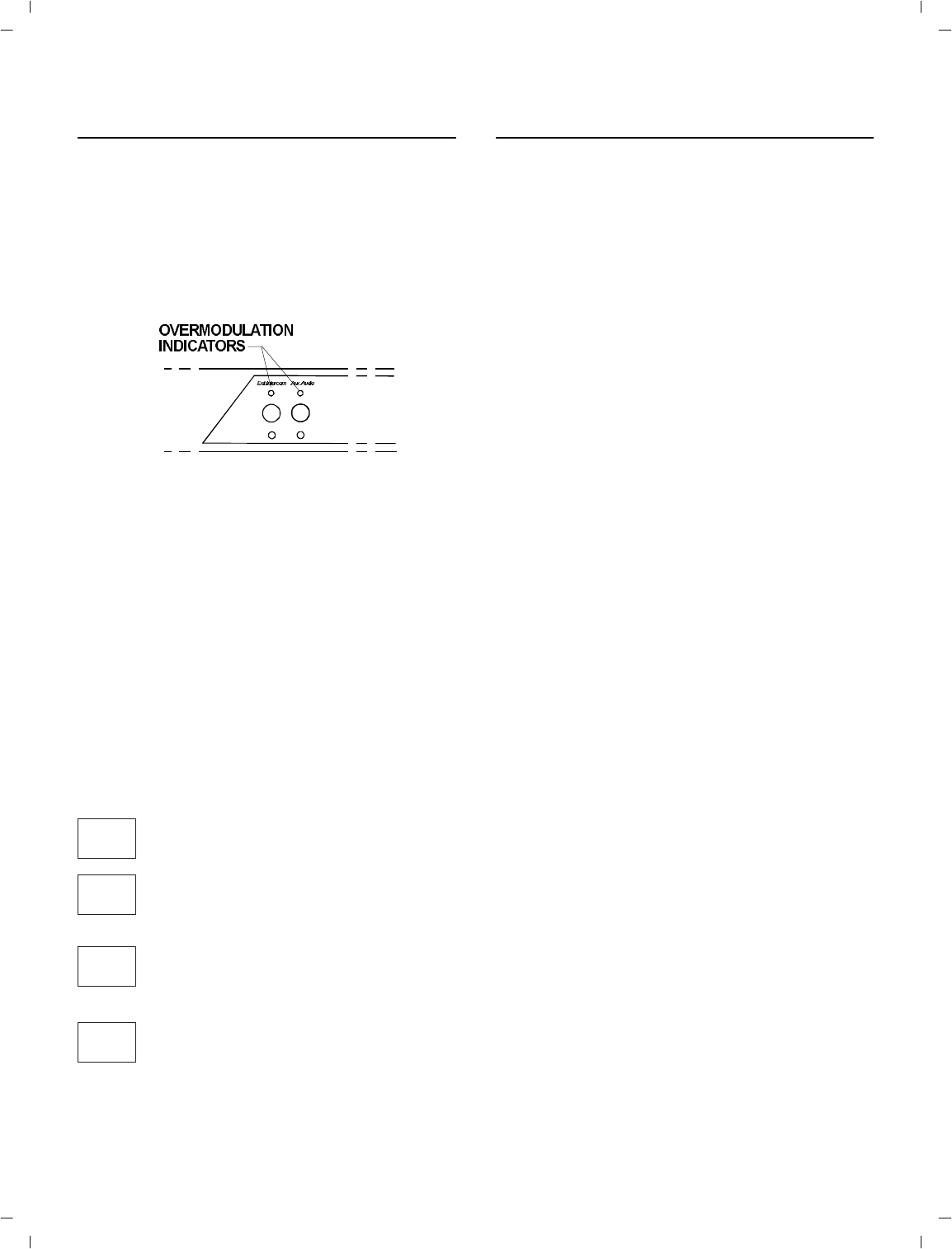
IN TER COM GAIN
If the au dio vol ume at the in ter com input is too
high, the LED will be il lu mi nated when the
per son on the in ter com is talk ing. De crease the
gain un til the LED does not il lu mi nate while
talk ing at nor mal vol ume. Oc ca sional flash ing
of the LED is al low able. See Fig ure 38.
Fig ure 38
Aux il iary Gain Con trols
AUX IL IARY GAIN
If the au dio vol ume at the aux il iary in put, is
too high, the Aux LED will be il lu mi nated
when the per son on the aux il iary is talk ing. De -
crease the aux il iary gain un til the aux il iary
LED does not il lu mi nate while talk ing at nor -
mal vol ume. Oc ca sional flash ing of the aux il -
iary LED is al low able. The aux il iary in di ca tor
has three states: OFF, HALF BRIGHT, AND
FULL BRIGHT. When the switch is “OUT”,
the in di ca tor is OFF. When the switch is “IN” it
be comes HALF BRIGHT, and when the in put
is overmodulated it be comes FULL BRIGHT.
SYS TEM WALK-THRU
Now that you have suc cess fully “set up” your
TELEX Wire less In ter com Sys tem and turned
on any aux il iary equip ment you are ready to
test the over all per for mance by “Walking”
the TELEX sys tem through the ar eas in which
you will be us ing it.
Be fore you be gin your walk-thru check the fol -
low ing:
TR-300 Bat tery Check.
Set mi cro phone gain in both the
TR-300 and the BTR-300.
Check the push-to-talk switch is en -
gaged in the Lock-to-talk po si tion.
LED will be il lu mi nated.
Por ta ble units to be used are en abled
at the Base.
The “sys tem walk-thru” can de tect prob lems of
weak sig nal strength caused by:
•Poor an tenna lo ca tion
•Wrong an tenna for re ceiver and/or trans -
mit ter.
•RF “Trou ble Spots”
•Op er ating dis tance be yond sys tem ca pa bil ity.
•Old or used bat ter ies in the TR-300
Un der nor mal con di tions the por ta ble car rier
in di ca tor LEDs on the BTR-300 should al ways
be lit when portables are trans mit ting. “Weak
Sig nal” con di tions will re sult in flash ing of the
Car rier LED.
In 99% of all in stances you will set up your
TELEX Wire lessIn ter com Sys tem, walk it
through and achieve er ror-free per for mance. If
in the rare in stance your TELEX Sys tem does
not “pass” dur ing your walk-thru eval u a tion,
re fer to the last sec tion of this man ual which
deals with Sys tem Trou ble shooting.
-29 -

TROU BLE SHOOTING
Re read the sec tions of this man ual to make
sure you have com pleted sys tem set-up prop -
erly
If you are un able to solve the prob lem, con tact
the dealer from whom you pur chased the sys -
tem for as sis tance.
PROB LEMSO LU TION
DIS TOR TION - Sys tem’s au dio qual ity
seems dis torted at me dium to high in put lev -
els.
Re duce mi cro phone gain by ad just ing mi -
cro phone gain con trol.
HISS - Sys tem seems to pro duce a “hiss”
which is un de sir able.Check the gain set ting on all beltpacks and
the base. They may be too low.
LOW OUT PUT - Sys tem pro duces a low
out put level.Check the gain set ting on both the beltpacks
and the base. They may be too low.
FEED BACK - Moving around area of use
pro duces “squeal” or “howl” in var i ous lo ca -
tions us ing ext. speak ers.
Re duce the gain set tings on both the
beltpacks and the base. They may be too
high.
DROP OUTS - When mov ing around the
area of use there seems to be lo ca tions where
the sig nal “swooshes” or com pletely dis ap -
pears.
Make sure both an ten nas on the base are
con nected and fol low the lo ca tion sug ges -
tions. Change the lo ca tion of the base unit
and an ten nas or avoid the bad ar eas with the
re mote beltpacks
.
IN TER FER ENCE - Sys tem picks up sig -
nals other than wire less In ter coms.Make sure Telex TR-300 beltpack is turned
on - this will usu ally elim i nate the in ter fer ing
sig nal. If not us ing a beltpack, make sure the
cor re spond ing en able switch at the base is
dis en gaged.
If prob lems per sist with the TR-300 beltpack
on, you will prob a bly need to have your sys -
tem’s fre quency changed to an other chan nel.
NO AU DIO from BASE or BELTPACK
head sets.Check Trans mit ter switch on base, use
CONT or RE MOTE po si tion. Check
push-to-talk func tion - is the switch ON?
-30 -
BAT TERY IN FOR MA TION
GEN ERAL
Im proper bat tery se lec tion, use, in stal la tion,
and care are the cause of nu mer ous wire less
sys tem fail ures.
CAU TION
DO NOT AT TEMPT TO CHARGE
ANY AL KALINE BAT TERIES WITH
THIS CHARGER.
EN ER GIZER® is a reg is tered trade mark of Un ion Car bide Cor po ra tion.
DURACELL® is a reg is tered trade mark of Duracell Inc.
Al ka line Bat teries: Al ka line bat ter ies such as
Mallory’s DURACELL or Everready’s EN ER -
GIZER pro vide the most re li able op er a tion in
wire less trans ceiv ers. The use of low cost car -
bon-zinc bat ter ies is NOT rec om mended.
AC-1NM BAT TERY CHARGER
NOTE: The AC-1NM is not sup plied with the
TR-300. See the “Ac ces sory” sec tion for or der -
ing in for ma tion.
The AC-1NM will charge the bat ter ies in two
TR-300’s si mul ta neously. In sert the plug from
the charger into the jack on the side of the
TR-300 and plug the charger into a 110 volt
out let.
Full charge of the bat tery pack is ob tained af ter
12 to 16 hours. A full charge will last 8 to 10
hours with ni-cads and 12-15 hours with nickle
metal hy drides.
Ex ten sive over-charging may dam age or de -
stroy the bat ter ies. Please en sure the charg ing
time does not ex ceed 16 hours.
Fig ure 39
AC-1 NM Bat tery Charger
-31 -
-32 -
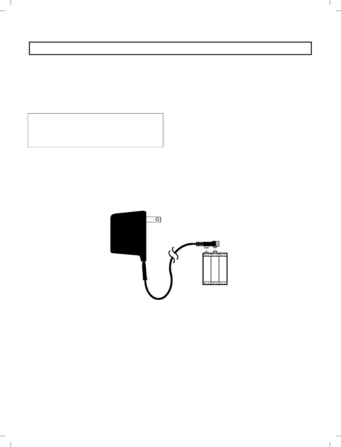
BC-4 NM BAT TERY CHARGER
NOTE: The BC-4 NM is not sup plied with the
TR-300. See “Ac ces sory” Sec tion for or der ing
in for ma tion.
Re move the bat tery holder from the TR-300.
CAU TION
DO NOT AT TEMPT TO CHARGE
ANY AL KALINE BAT TERIES WITH
THIS CHARGER.
Snap the ter mi nal con nec tor onto the bat tery
holder and plug the charger into a 110 Volt out -
let.
Full charge of the bat tery pack is ob tained af ter
12 to 16 hours. A full charge will last 8 to 10
hours with ni-cads and 12 to 15 hours with
nickle-metal hy drides.
Ex ten sive over-charging may dam age or de -
stroy the bat ter ies. Please en sure the charg ing
time dores not ex ceed 16 hours.
Fig ure 40
BC-4 NM Bat tery Charger
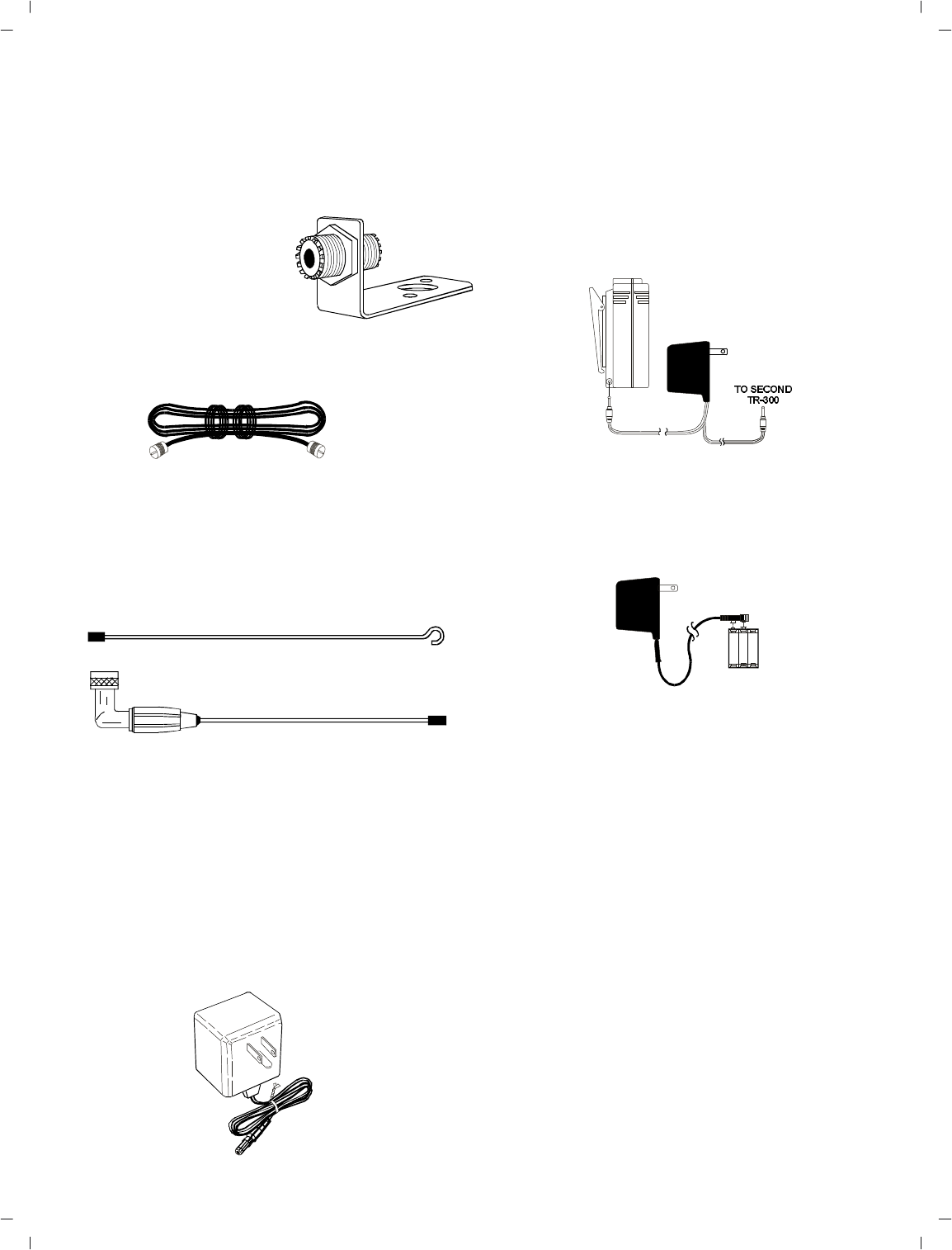
AC CES SORIES
Mi cro phone Stand/SurfaceMount Bracket -
For 5/8-wave an tenna.
In cludes nec es sary hard ware.
Or der No.
25’ Coax Ca ble
Or der No. 63901-000
4’ Coax Ca ble
Or der No. 63901-001
5/8-Wave An tenna -
Screw apart for easy stor ing.
Or der No. Color Fre quency
Code Range
879248-1Blue150-168.9 MHz
879248-2Yellow169-184.9 MHz
879248-3White185-199.9 MHz
879248-4Red200-216 MHz
AC Power Sup ply 12 Volt, 60 HZ
Or der No. 730131-000
AC-1NM Bat tery Charger -
Or der No. 70741-001
In cludes 6 nickle-metal hy dride bat ter ies and 1
car rier. Charges 1 or 2 TR-300’s with out re -
mov ing the bat tery pack.
BC-4NM Bat tery Charger
Or der No. 70741-002
In cludes 6 nickle-metal hy dride bat ter ies and 1
car rier. Charges 1 set of bat ter ies out side of the
TR-300.
NMBP Bat tery Pack
Or der No. 70741-003
6 nickle-metal hy dride bat ter ies and car rier.
For use with AC-1NM and BC-4NM
Telex Con fig u ra tion
Or der No.
PH-4.............. 70340-100
PH-8.............. 70415-100
HR-1............300534-007
HR-2............300534-000
RTS Con fig u ra tion
Or der No.
PH-4R............ 70340-102
PH-8R............ 70415-102
HR-1R...........300534-008
HR-2R...........300534-001
-33 -

-34 -
CUS TOMER SER VICE IN FOR MA TION
If your re ceiver or trans mit ter should need ser vic ing un der the war ranty, please con tact:
Cus tomer Ser vice De part ment
TELEX COM MU NI CA TIONS, INC.
8601 East Cornhusker High way,
P.O. Box 5579,
Lin coln, Ne braska 68505-5579 U.S.A.
Phone: (402) 467-5321 or 465-7021
All claims of de fect or short age should be sent to the above ad dress. When re turn ing
items for ser vice, you must pro vide date and proof of pur chase, such as a copy of the
sales re ceipt, to es tab lish war ranty. A let ter should be in cluded out lin ing all symp toms
and claimed de fects. In for ma tion on how the equip ment was in stalled and used is very
help ful. Please in clude your phone num ber and re turn ad dress in case our ser vice tech ni -
cians need to con tact you.
Units that have been mod i fied can not be ac cepted for re pair.
In clude all in for ma tion re quested by the Ser vice De part ment. Then pack the unit as fol -
lows:
Check the unit to see that all parts and screws are in place. Then wrap it in heavy pa per or
put it in a plas tic bag. If the orig i nal car ton is not avail able, place the unit in a strong c ar -
ton that is at least six inches big ger in all three di men sions than the unit. Fill the car ton
equally around the unit with re sil ient pack ing ma te rial (shred ded pa per, foam, etc.). Seal
it with gummed pa per tape, tie it with a strong cord, and ship it by pre paid ex press,
United Par cel Ser vice or in sured par cel post to the Telex Ser vice De part ment.
It is very im por tant that the ship ment be well-packed and fully in sured. Dam age claims
must be set tled be tween you and the car rier and this can de lay re pair and re turn of the
unit to you.
Telex re serves the right to make changes in de sign and im prove ment on its prod uct with -
out as sum ing any ob li ga tion to in stall the same on any of its prod ucts pre vi ously man u -
fac tured. Fur ther Telex re serves the right to ship new and/or im proved prod ucts which are
sim i lar to the form, fit and func tion of prod ucts orig i nally or dered.

-35 -
FCC IN FOR MA TION
The Telex Models BTR-300 and TR-300 transceivers are Type
Accepted under United States Federal Communications
Commission Parts 90 and 74. Licensing of Telex equipment is
the user’s responsibility and licensability depends upon the user’s
classification, user’s application, and frequency selected. Telex
strongly urges the user to contact the appropriate
telecommunications authority for any desired clarification.
CAUTION: Changes or modifications made by the user could
void the user’s authority to operate the equipment.

9600 Aldrich Ave. So., Min ne ap o lis, Min ne sota, 55420 U.S.A.
PN 80 Oct. 1999Made in U.S.A