Bosch Security Systems M520 BELTPACK TRANSCEIVER User Manual Telex Model TR 1 Beltpack
Bosch Security Systems, Inc. BELTPACK TRANSCEIVER Telex Model TR 1 Beltpack
UserManual.wiki
>
Bosch Security Systems
>
M520 User Manual
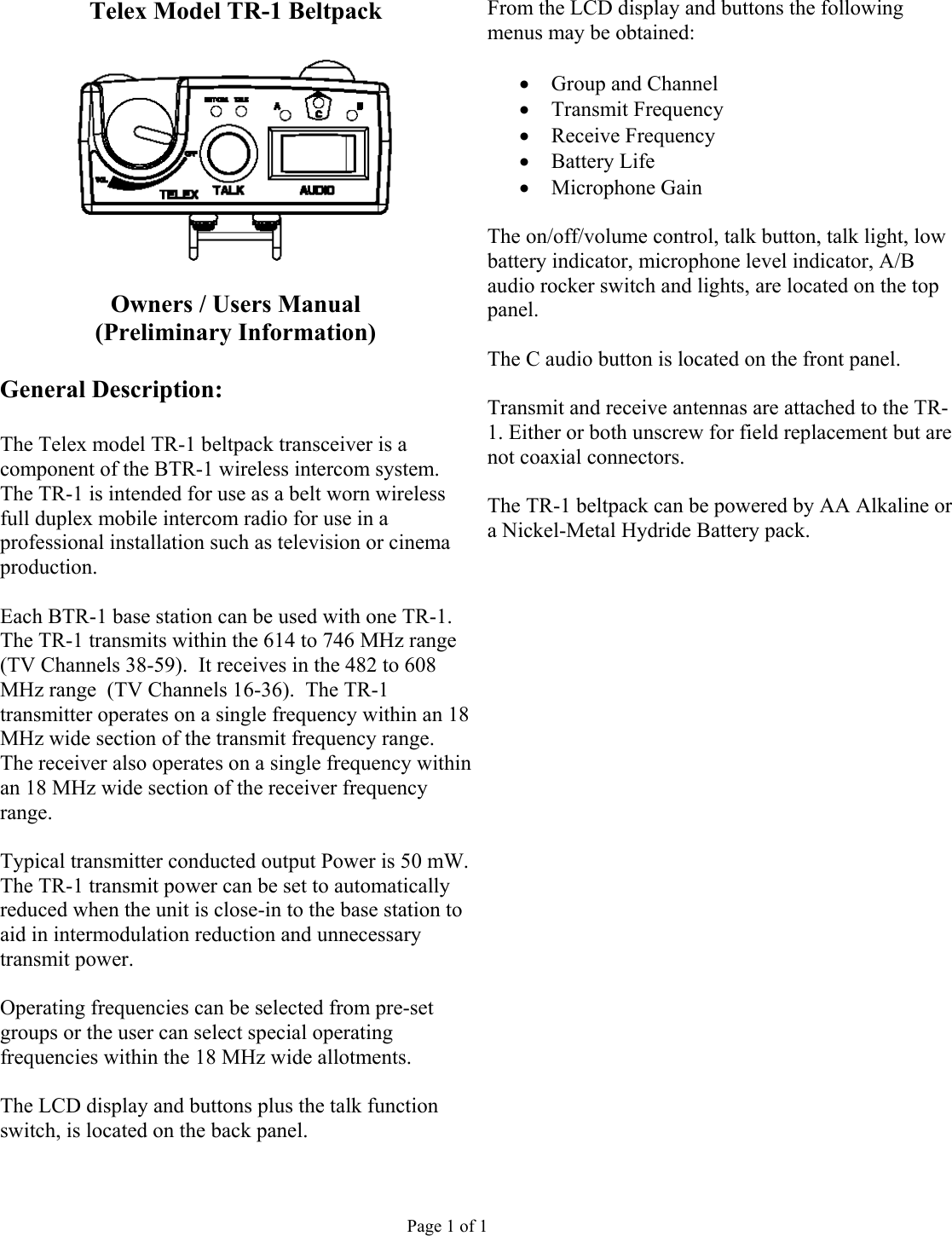
USERS MANUAL
Navigation menu
Upload a User Manual
Namespaces
Wiki Guide
HTML
PDF
Info
Views
User Manual
Discussion / Help
Navigation
![Controls and Connections 1. On/Off & Volume Control – Turns the beltpack power on and controls headset volume. 111095 6 8 7 4 53 2 1 15 141312 9. [MENU] and [SET] buttons – Used to select menus and set options on the LCD. 2. BAT/O.M. Light – Battery - Light flashes once on power up = Battery OK 10. LCD display. Light on continuously = Battery Low Light does not flash or come on = Battery Dead 11. [UP] and [DOWN] buttons - Used to select menus and set options on the LCD. Microphone Lvl: Light flashes on loudest speech = Gain OK Light flashes on all speech = Gain too High 12. Push-to-Talk/Push-to-Transmit Switch – Light never flashes on loudest speech = Gain too Low PT TALK (Push-to-Talk) – The transmitter is always on. No audio is sent unless the talk button is active. Recommended position. 3. Talk Light – Light on if talk button active. 4. Talk Button – Press to enable the audio path from the headset. PT TX (Push-to-Transmit) – The transmitter and audio path are off except when the talk button is active. Software Selectable modes: Push-to-Talk Push-to-Latch 13. Headset Connector – XLR Plug for Telex units, XLR Receptacle for RTS units. 5. A and B Lights – “A” light is on if Selection Switch in A position. “B” light is on if Selection switch in B position. 14. Battery Latch – Press down to enable the battery pack to be released. While the latch is held down, slide the battery pack about 1/8 inch back, toward the latch, until it stops, then lift out. 6. Selection Switch – Switches between base station presets A or B. 7. “C” Pushbutton – Press to enable the base station “C” presets. Software Selectable modes: Push-to-Talk 15. Receive and Transmit Antennas – The antennas are screw type, ¼ wave, replaceable antennas. The color dot on the screw end of the antenna must match color dot on antenna receptacle. Push-to-Latch Off 8. “C” Button Light – “C” light is on if “C” pushbutton active. Page 2 of 2](https://usermanual.wiki/Bosch-Security-Systems/M520/User-Guide-452055-Page-2.png)
