Bosch Security Systems PR-ZB Motion Sensor User Manual F01U314039 02c RFPR ZB ING indd
Bosch Security Systems, Inc. Motion Sensor F01U314039 02c RFPR ZB ING indd
Users Manual
en Installation Guide
RADION PIR ZB
Wireless Motion Detector
RFPR-ZB/RFPR-ZB-EU/RFPR-ZB-CHI
RFPR-ZB-ES/RFPR-ZB-MS
© 2016 Bosch Security Systems, Inc. F.01U.314.039 | 02c | 2016.05
Bosch Security Systems, Inc.
130 Perinton Parkway
Fairport, NY 14450
USA
www.boschsecurity.com
Bosch Sicherheitssysteme GmbH
Robert-Bosch-Ring 5
85630 Grasbrunn
Germany
0246810
0 7 13 20 26 33
0
6
4
2
0
2
4
6
0
20
13
7
0
7
13
20
12
40
≥2.3 ≥7.5
≤2.7 ≤9
Feet
Feet
Meters
Meters
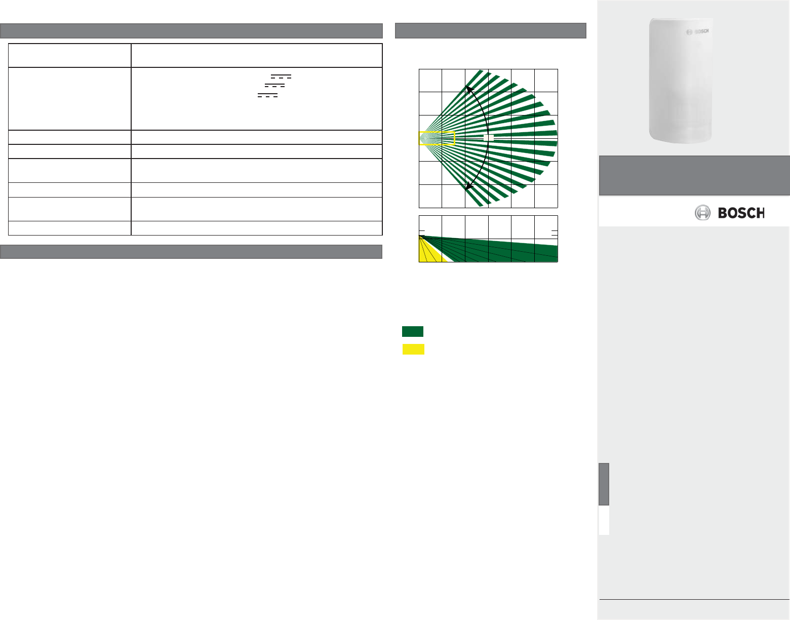
90°
Top: Overhead view
Bottom: Side view
FCC
This device complies with part 15 of the FCC Rules. Operation is subject to the following two
conditions:
(1) This device may not cause harmful interference, and (2) this device must accept any
interference received, including interference that may cause undesired operation.
This equipment has been tested and found to comply with the limits for a Class B digital
device, pursuant to part 15 of the FCC Rules. These limits are designed to provide reasonable
protection against harmful interference in a residential installation. This equipment generates,
uses and can radiate radio frequency energy and, if not installed and used in accordance with
the instructions, may cause harmful interference to radio communications. However, there is no
guarantee that interference will not occur in a particular installation.
If this equipment does cause harmful interference to radio or television reception, which can
be determined by turning the equipment off and on, the user is encouraged to try to correct the
interference by one or more of the following measures:
– Reorient or relocate the receiving antenna.
– Increase the separation between the equipment and receiver.
– Connect the equipment into an outlet on a circuit diff erent from that to which the receiver
is connected.
– Consult the dealer or an experienced radio/TV technician for help
IC
Under Industry Canada regulations, this radio transmitter may only operate using an antenna of
a type and maximum (or lesser) gain approved for the transmitter by Industry Canada.
To reduce potential radio interference to other users, the antenna type and its gain should be so
chosen that the equivalent isotropically radiated power (e.i.r.p.) is not more than that necessary
for successful communication.
Conformément à la réglementation d’Industrie Canada, le présent émetteur radio peut
fonctionner avec une antenne d’un type et d’un gain maximal (ou inférieur) approuvé pour
l’émetteur par Industrie Canada.
Dans le but de réduire les risques de brouillage radioélectrique à l’intention des autres
utilisateurs, il faut choisir le type d’antenne et son gain de sorte que la puissance isotrope
rayonnée équivalente (p.i.r.e.) ne dépasse pas l’intensité nécessaire à l’établissement d’une
communication satisfaisante.
Key
Dark green - PIR detection zones
Yellow - PIR detection look-down zones
Coverage Pattern
Specifi cations
Dimensions 2.4 in x 4.3 in x 1.7 in
(60 mm x 108 mm x 42 mm)
Batteries Panasonic CR123A Lithium 3 VDC
Duracell DL123A Lithium 3 VDC
Sanyo CR123A Lithium 3 VDC
Battery life for one battery is up to 7 years. Adding a
second battery (optional) can increase battery life up to 10 years
total.
Battery capacity 1500 mA
Pet immunity Up to 45 lbs (20 kg).
Operating temperature -20°F to +130°F
(-30°C to +55°C)
Non-condensing humidity 0% to 93%
Mounting height 7.5 ft to 9 ft
(2.3 m to 2.7 m)
Use For indoor use only
PRELIMINARY
Bosch Security Systems, Inc. | 2
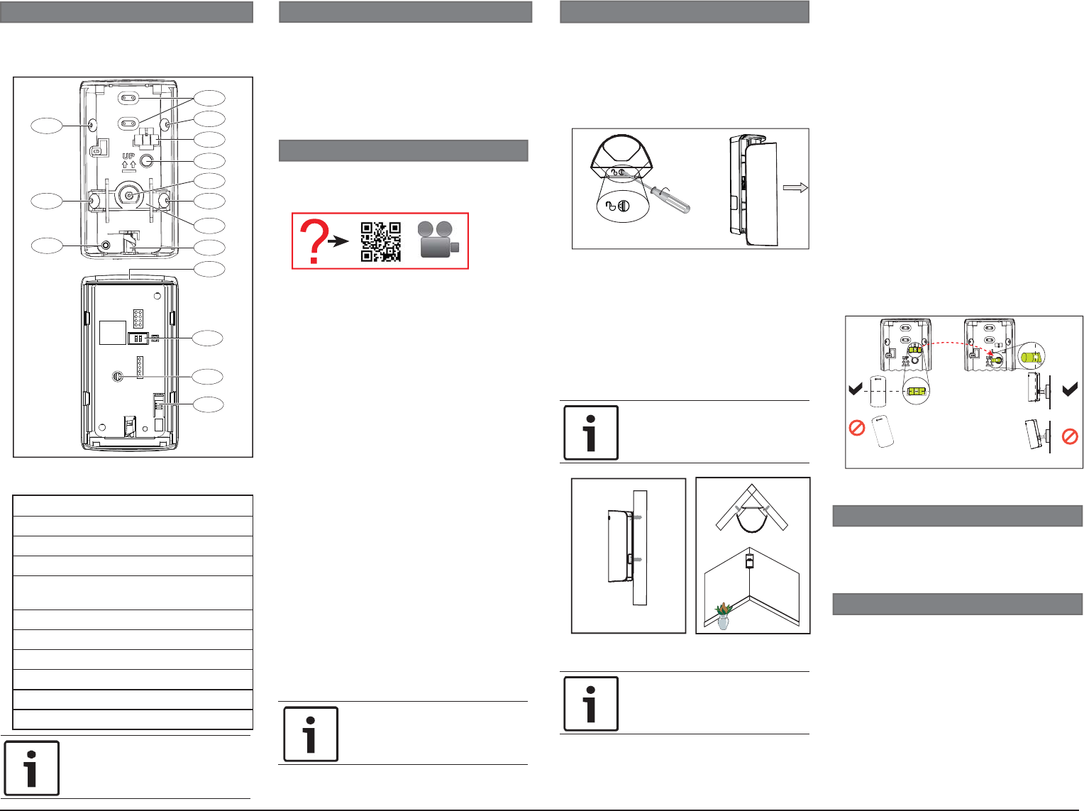
Callout ― Description
1 ― Flat surface mounting holes
2 ― Corner surface mounting holes
3 ― Removable bubble level horizontal
4 ― Bubble level holder (swivel mount
only)
5 ―
Tamper plate
6 ― Rotary lock
7 ― Battery tray location
8 ― Feature switches
9 ― Look-down adjustment
10 ― Tamper switch
1
3
4
5
6
1
2
8
9
7
10
1
2
22
1 | Overview
3 | Installation considerations
4 | Installation
Figure 1.1: Detector base interior view
(top), detector body interior view (bottom)
The RADION PIR ZB is a wireless motion
detector with ZigBee technology that has a
dense zone pattern, and is easy to install.
Point away from:
– Glass exposed to the outdoors
– Direct and indirect sunlight
– Objects that change temperature
rapidly such as heat sources or air
conditioning outlets
– Outside traffi c
– Objects animals might climb on
(stairs, shelves, furniture)
Install:
– On solid, vibration free surface
– On a fl at or corner surface
– Within recommended mounting height
range measured from the fl oor
– Where an intruder is most likely to
cross through the coverage pattern
Do not install:
– Near rotating machines or other
moving objects within the coverage
pattern
– Near objects that can block the fi eld-
of-view
– Where an intruder would only walk
directly toward or away from the
detector
– Near direct hot or cold drafts
Pet immunity:
– Up to 45 lbs (20 kg).
Open the detector and mount the base to
either a fl at surface, a corner, or a bracket.
Opening the detector:
1. Turn the rotary lock at the bottom of the
detector to the open position. The body
slides down. Refer to Figure 4.1.
2. Pull apart to remove it from the base.
Figure 4.1: Unlock and open detector
Mounting the base:
1. Identify mounting location and surface
for install. (Optional mounting brackets:
B335 and B338. Sold separately).
2. Identify mounting holes to use based on
the mounting surface. Refer to Figure 1.1.
3. Break away or drill through the
appropriate mounting hole coverings in
the base.
1
NOTICE!
Do not break away or separate the
tamper plate from the base.
Figure 4.2 Surface mount: left; corner
mount: right
Leveling the motion detector:
1. Position the base on the surface and
mount in place using one screw and
drywall anchor only. Do not over-tighten.
2. Use the bubble level to ensure the base
is level from side to side. Refer to Figure
4.3-A.
3. Remove the bubble level and place it into
the bubble level holder to verify vertical
alignment. This is applicable for swivel
mount brackets only. Refer to Figure
4.3-B.
4. Make adjustments until the base is level,
and mark the remaining surface mounting
hole locations.
5. Remove the bubble level from the holder
and place it back to its original position.
6. Secure the base with the remaining
screws and drywall anchors. Use a total
of 3 screws and drywall anchors for
surface mount installations, and 2 screws
and drywall anchors for corner mount
installations.
Figure 4.3: Level detector
5 | Confi guration
Setting the switches:
1. Switch 2 - LED illumination. The LED
illuminates when the device detects PIR
activity. By default, the LED is disabled
(switch down). If you do not want the
LED indication after you fi nish the set up
and walk tests, place the switch in the
off position (switch down).
Confi gure the features and options located on
the detector body before placing the detector
body on the base.
5.1 | Set the switches
2
NOTICE!
Use of a bracket might reduce
range and increase dead zone
areas.
NOTICE!
At least one screw must be
inserted into the tamper switch
for tamper protection.
A. B.
NOTICE!
Supported mounting heights range
from 7.5 ft to 9 ft (2.3 m to 2.7 m).
2 | Product Contents
This poduct contains:
– Wireless motion detector
– Installation instructions
– Hardware pack
– Battery tray with one battery
You will need a power drill and a fl at-head
screwdriver to perform the installation.
Use a smart phone and scan the following
QR code for more information regarding
installation and mounting considerations.
PRELIMINARY
Bosch Security Systems, Inc. | 3
LED illumination Switch setting
Table 5.1: Switch settings
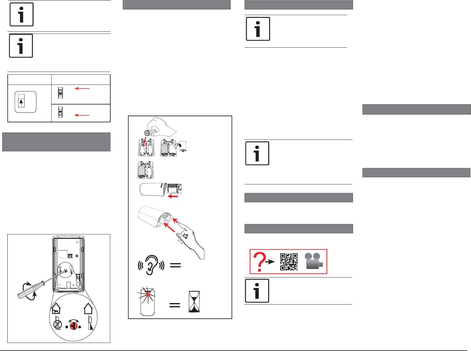
5.2 | Look-down and Pet
immunity switch
NOTICE!
To preserve battery life, LED
indications are visible only after
3 minutes have passed since the
previous alarm restoral when the
LED switch is set to on.
The motion detector has a rotary switch to
enable or disable the look-down zone and pet
immunity. Refer to Figure 5.2.
• Enable the look-down zone by turning the
dial to the right. Use this to detect motion
in the area underneath the device. This
also disables pet immunity and increases
sensitivity by approximately 20% for use in
higher security applications.
• Disable the look-down lens to avoid false
alarms from objects moving in the area
underneath the device. This also enables
pet immunity in applications with pets.
2
ON
OFF
2
ON
OFF
ON
OFF
2LED
NOTICE!
Product must be walk tested at
least once each year.
NOTICE!
If the controller does not discover
the motion detector within three
minutes, the motion detector exits
pairing mode. The motion detector
restarts pairing when motion is
detected.
7 | Pairing process
The unit powers up when batteries are
installed. Slide the detector body onto the
mounted base.
Pairing the detector with the controller:
1. The red LED lights for two seconds,
then the detector enters pairing mode.
2. The red LED fl ashes three times
every fi ve seconds until the controller
discovers the detector. Complete the
next step within three minutes to limit
battery consumption.
3. As soon as the detector enters pairing
mode, go to the controller and complete
the pairing process according to the
controller manufacturer’s instructions.
8 | Complete the setup
Follow the instructions below to walk test the
motion detector.
8.1 | Walk test the detector
8.2 | Complete the walk test
1. Once you complete the walk test, do not
disturb the detector’s coverage pattern
for 90 seconds.
2. After 80 seconds, the detector fl ashes
red to indicate the walk test time is
about to expire.
3. After fl ashing for 10 seconds, the
detector exits walk test mode.
The battery tray in this device has two
compartments. The device requires only one
battery to operate (included) and is already
installed. You can add a second battery (not
included) to extend battery life. If installing
for the fi rst time, remove the battery
cardboard insert.
To install the batteries:
1. Slide the battery tray into the detector
body using two fi ngers with the fi nger
cavity facing out. Be certain to slide the
tray in until the top of the tray is fl ush
with the top of the detector body and
you feel it “click” into position. The LED
stays lit for 2 seconds immediately after
the battery “clicks” into place. Refer to
battery insertion sequence in Figure 6.1.
Figure 5.2: Look-down adjustment
6 | Battery installation
Use a smart phone and scan the following QR
code for additional information on walk test.
1.
2.
+
+
++
+
++
Figure 6.1: Battery insertion
I
+
I
+
+
I
3.
4.
“Click”
5.
2 sec
9 | Operation and maintenance
In the normal operating mode, an alarm is
transmitted only after three minutes have
passed since the previous alarm restoral.
This three minute lockout time reduces
unnecessary RF transmissions in high traffi c
areas thereby extending battery life.
It is recommended to clean the detector lens
periodically using a moisten cloth dipped in
water.
Performing the walk test:
1. Remove the detector body from the base
then slide it back on. This starts a 15
second timer. The LED fl ashes red during
this time. As soon as the LED fl ashing
has completed, walk test mode starts.
2. Once started, the detector remains in
walk test mode for as long as it senses
motion. If no motion is detected for 90
seconds, the unit exits walk test mode.
Be sure to begin walk testing within the
90 second window.
3. Start the walk test from the farthest
point of the sensor’s coverage pattern.
4. During the walk test, observe the LED
colors.
• Red indicates PIR activity
NOTICE!
Verify your home control system or
security control panel is powered
up and operational before
beginning the pairing process.
NOTICE!
The LED is active during the
pairing process and walk test
regardless of the setting of Dip
switch 2.
PRELIMINARY
Bosch Security Systems, Inc. F.01U.314.039 | 02c | 2016.05 | 4
Copyright
This document is the intellectual property of Bosch Security Systems, Inc., and is protected
by copyright. All rights reserved.
Trademarks
All hardware and software product names used in this document are likely to be registered
trademarks and must be treated accordingly.
Bosch Security Systems, Inc. product manufacturing dates
Use the serial number located on the product label and refer to the
Bosch Security Systems, Inc. website at http://www.boschsecurity.com/datecodes/.
Region Agency Certifi cation
US and
Canada
Control No.3170792
Conforms to ANSI/UL Std. 639
Conforms to ULC Std. S306-03
FCC FCC Part 15 Class B
IC 1249A-PRZB
ZigBee This ZigBee® Certifi ed product works in global 2.4 GHz
networks supporting ZigBee HA 1.2. ZigBee® Certifi ed is a
registered trademark of the ZigBee Alliance. ZigBee Cert
No.xxxx ZigBee Cert No.
10 |
Certifi cations
®
NOTICE!
Replace all old batteries with new
ones. Do not mix between old
batteries and new batteries.
9.2 | Detector reset
Unlock and open the detector then follow the
steps below to reset the detector to factory
settings:
1. Remove the battery tray.
2. Press and hold the tamper switch.
3. Reinsert the battery tray.
4. Release the tamper switch within
four seconds after the battery tray is
reinserted.
5. Slide the detector body onto the base.
The detector LED fl ashes to indicate it
is reset.
6. Repeat section 7 and 8 completely to
pair the detector.
NOTICE!
The detector can also be reset
remotely through the supporting
controller.
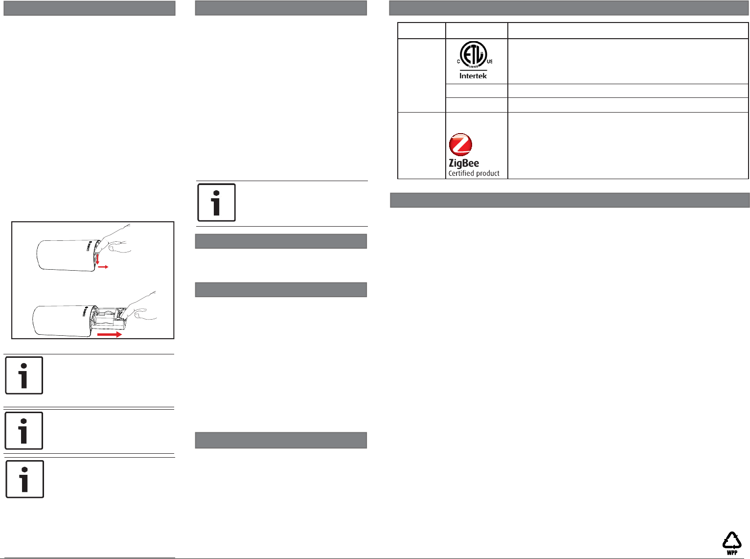
9.1 | Battery replacement
Perform the following to replace the
batteries:
1. Remove the detector from the base.
Refer to Section 4 Installation to unlock
the detector.
2. Hold the detector body with one hand.
With the other hand, insert the tip of
your fi nger into the cavity at the top of
the battery tray.
3. Press down while sliding the tray
completely out of the motion detector
body. Refer to Figure 9.1.
4. Insert one or two batteries, observing
proper polarity. Refer to the diagram on
the battery tray for proper positioning.
5. Slide the battery tray into the detector
body using two fi ngers with the fi nger
cavity facing out. Be certain to slide the
tray in until the top of the tray is fl ush
with the top of the detector body until
you feel it “click” into position.
Figure 9.1: Removing the battery tray
NOTICE!
Battery life for one battery is good
up to 7 years. Using a second
battery (optional) can increase
battery life up to 10 years total.
NOTICE!
Bosch is committed to responsible
environmental stewardship. Please
dispose of batteries in accordance
with local laws and regulations in
your area. Contact your local waste
disposal authorities or consult
www.e-cyclingcentral.com to fi nd
an electronics recycling center
near you.
10.1 | Low battery
A trouble status reported on the controller
might be the result of low batteries on the
detector. To trouble-shoot the condition,
begin by replacing the batteries. Refer to
Section 4 Installation to unlock the detector
and Section 9.1 Battery replacement to open/
replace batteries. Replacing the detector:
1. Slide the detector back onto the base.
2. This starts a 15 second timer. The LED
cycles red, green, and yellow during this
time. As soon as the LED cycling has
completed, walk test mode starts.
3. Complete all steps in Section 7.
10 | Troubleshooting
Refer to the following sections for
troubleshooting information.
10.2 | Detector malfunction
A trouble or error status might occur when
the detector experiences a failure (for
example low battery, detection failure). This
is indicated by a single red LED fl ash every
10 seconds during normal operation, or by a
rapid sequence of four red LED fl ashes when
the detector attempts to enter walk test
mode. Check your control panel status for
more information.
PRELIMINARY