Bosch Security Systems RF1100 Wireless Glass Break Transmitter User Manual Exhibit D Users Manual per 2 1033 b3
Bosch Security Systems Inc Wireless Glass Break Transmitter Exhibit D Users Manual per 2 1033 b3
UserManual.wiki
>
Bosch Security Systems
>
RF1100 User Manual
Exhibit D Users Manual per 2 1033 b3
Navigation menu
Upload a User Manual
Namespaces
Wiki Guide
HTML
PDF
Info
Views
User Manual
Discussion / Help
Navigation
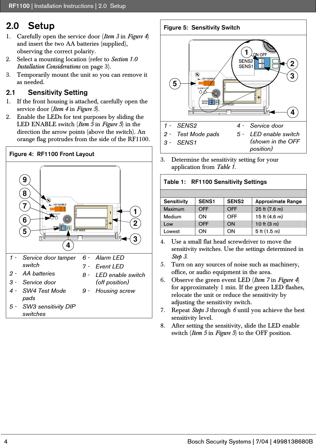
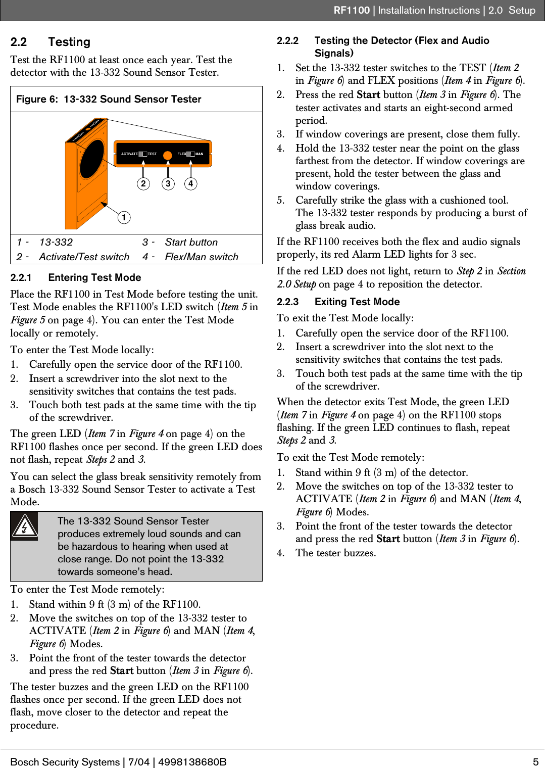
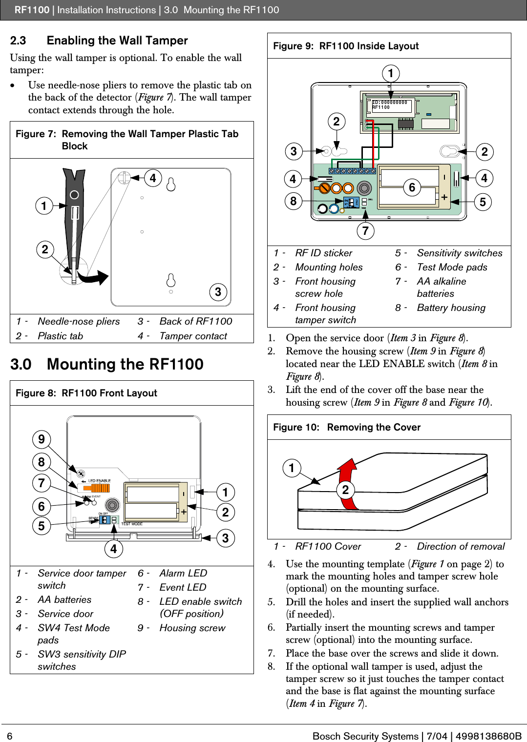
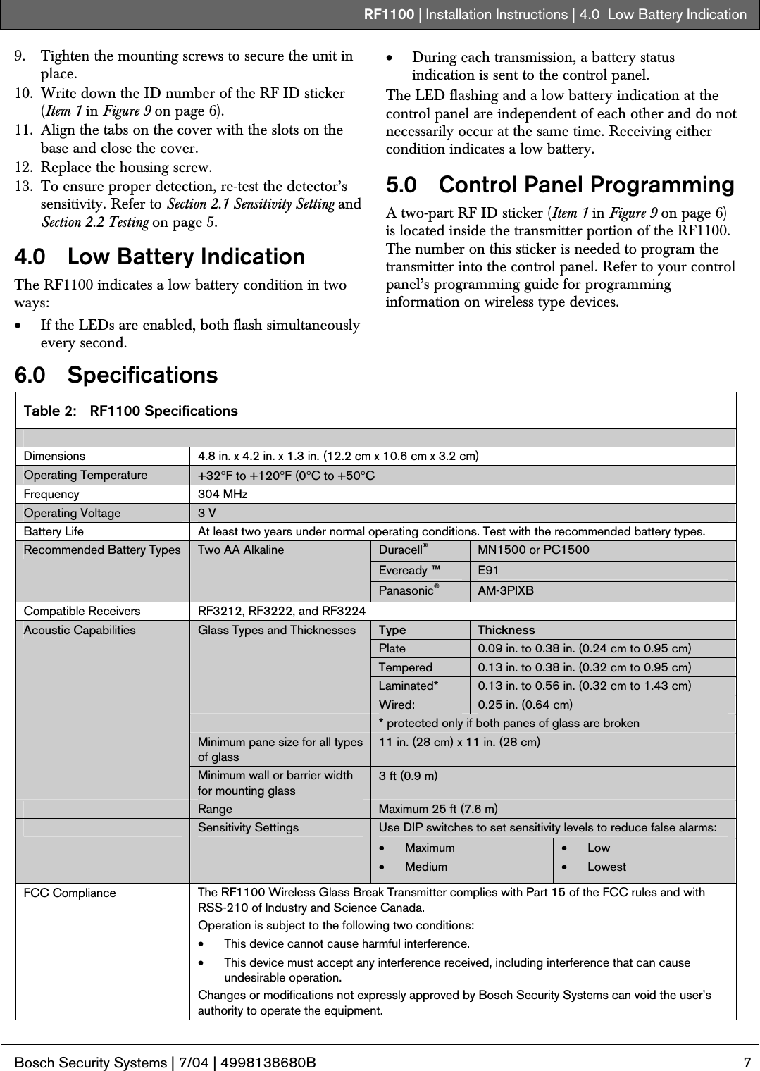
![RF1100 | Installation Instructions | 1.0 Installation Considerations . Bosch Security Systems | 7/04 | 4998138680B 3 1.0 Installation Considerations Mount the RF1100 on flat surfaces such as ceilings and walls. Mount the unit to optimize glass break detection. Refer to Figure 2 and Figure 3 for mounting examples. In normal residential or commercial applications, locate the RF1100 within 325 ft (100 m) of its assigned receiver. For best detector performance, select a mounting location that is: • within 25 ft (7.6 m) of the protected glass • within clear view of the protected glass (there is no minimum range) • at least 6.5 ft (2 m) from the floor • at least 3.3 ft (1 m) from forced-air ducts • at least 3.3 ft (1 m) from sirens or bells (greater than 2 in. [5 cm] in diameter) • mounted on a window frame if any heavy window covering is present Avoid mounting the detector: • in a corner • on the same wall as the protected glass • on free-standing posts or pillars • in rooms with noisy equipment such as air compressors, bells, and power tools Test the detector in the desired mounting location before drilling mounting holes. Refer to Section 2.2 Testing on page 5. The RF1100’s maximum outside RF range is approximately 1000 ft (300 m). Figure 2: Wall Mounting Locations (top view) 751243633 1 - Poor location - fully opened door can block detector’s range3 2 - Poor location - high risk of door slam noise3 3 - 25 ft (7.6 m) maximum mounting distance 4 - Window 5 - Best locations1 6 - Satisfactory location2 7 - Satisfactory location if a heavy window covering is present2 Figure 3: Ceiling Mounting Locations (side view) 14352 1 - Best locations1 2 - Ceiling 3 - 25 ft (7.6 m) maximum mounting distance 4 - Glass 5 - Floor 1 Best location: where the RF1100 is most effective. 2 Satisfactory location: where the effectiveness of the RF1100 can be reduced. 3 Poor location: where the effectiveness of the RF1100 is impaired.](https://usermanual.wiki/Bosch-Security-Systems/RF1100/User-Guide-457029-Page-3.png)