Bosch Security Systems RF1100 Wireless Glass Break Transmitter User Manual Exhibit D Users Manual per 2 1033 b3
Bosch Security Systems Inc Wireless Glass Break Transmitter Exhibit D Users Manual per 2 1033 b3
Exhibit D Users Manual per 2 1033 b3
EN
Installation Instructions
Wireless Glass Break
Transmitter
RF1100
RF1100 | Installation Instructions | Trademarks
2 Bosch Security Systems | 7/04 | 4998138680B
Trademarks
Duracell® is a registered trademark of The Gillette Company.
Eveready™ is a trademark of Eveready Battery Company, Inc.
Panasonic® is a registered trademark of Matsushita Electric Industrial Co., Ltd.
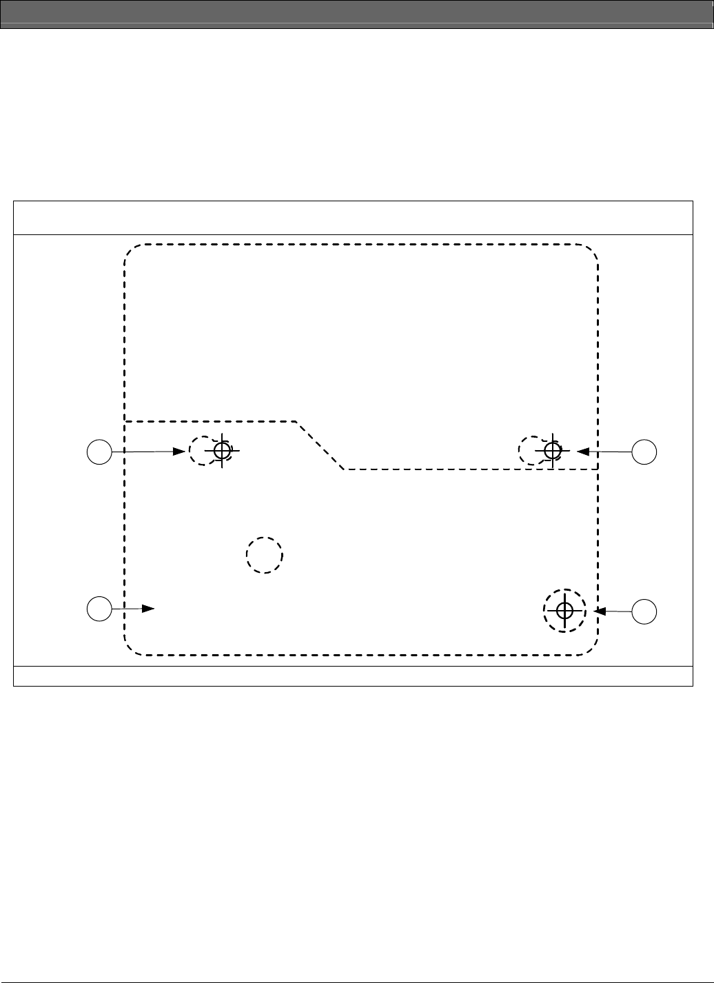
Figure 1: RF1100 Mounting Template (Actual size)
3
2 2
1
1 - Wall tamper screw (optional) 2 - Mounting screw 3 - Base of RF1100
RF1100 | Installation Instructions | 1.0 Installation Considerations
.
Bosch Security Systems | 7/04 | 4998138680B 3
1.0 Installation Considerations
Mount the RF1100 on flat surfaces such as ceilings and
walls. Mount the unit to optimize glass break detection.
Refer to Figure 2 and Figure 3 for mounting examples.
In normal residential or commercial applications,
locate the RF1100 within 325 ft (100 m) of its assigned
receiver.
For best detector performance, select a
mounting location that is:
• within 25 ft (7.6 m) of the protected
glass
• within clear view of the protected
glass (there is no minimum range)
• at least 6.5 ft (2 m) from the floor
• at least 3.3 ft (1 m) from forced-air
ducts
• at least 3.3 ft (1 m) from sirens or
bells (greater than 2 in. [5 cm] in
diameter)
• mounted on a window frame if any
heavy window covering is present
Avoid mounting the detector:
• in a corner
• on the same wall as the protected
glass
• on free-standing posts or pillars
• in rooms with noisy equipment such as
air compressors, bells, and power tools
Test the detector in the desired mounting
location before drilling mounting holes.
Refer to Section 2.2 Testing on page 5.
The RF1100’s maximum outside RF range is
approximately 1000 ft (300 m).
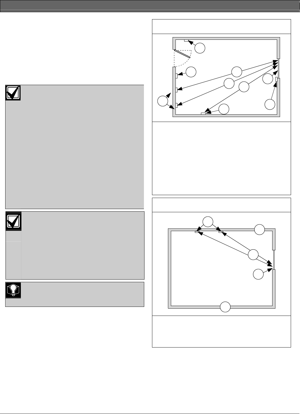
Figure 2: Wall Mounting Locations (top view)
7
5
1
24
3
6
3
3
1 - Poor location -
fully opened door
can block
detector’s range3
2 - Poor location -
high risk of door
slam noise3
3 - 25 ft (7.6 m)
maximum
mounting distance
4 - Window
5 - Best locations1
6 - Satisfactory
location2
7 - Satisfactory
location if a heavy
window covering
is present2
Figure 3: Ceiling Mounting Locations (side view)
1
4
3
5
2
1 - Best
locations1
2 - Ceiling
3 - 25 ft (7.6 m) maximum
mounting distance
4 - Glass
5 - Floor
1 Best location: where the RF1100 is most effective.
2 Satisfactory location: where the effectiveness of the RF1100 can
be reduced.
3 Poor location: where the effectiveness of the RF1100 is impaired.
RF1100 | Installation Instructions | 2.0 Setup
4 Bosch Security Systems | 7/04 | 4998138680B
2.0 Setup
1. Carefully open the service door (Item 3 in Figure 4)
and insert the two AA batteries (supplied),
observing the correct polarity.
2. Select a mounting location (refer to Section 1.0
Installation Considerations on page 3).
3. Temporarily mount the unit so you can remove it
as needed.
2.1 Sensitivity Setting
1. If the front housing is attached, carefully open the
service door (Item 4 in Figure 5).
2. Enable the LEDs for test purposes by sliding the
LED ENABLE switch (Item 5 in Figure 5) in the
direction the arrow points (above the switch). An
orange flag protrudes from the side of the RF1100.
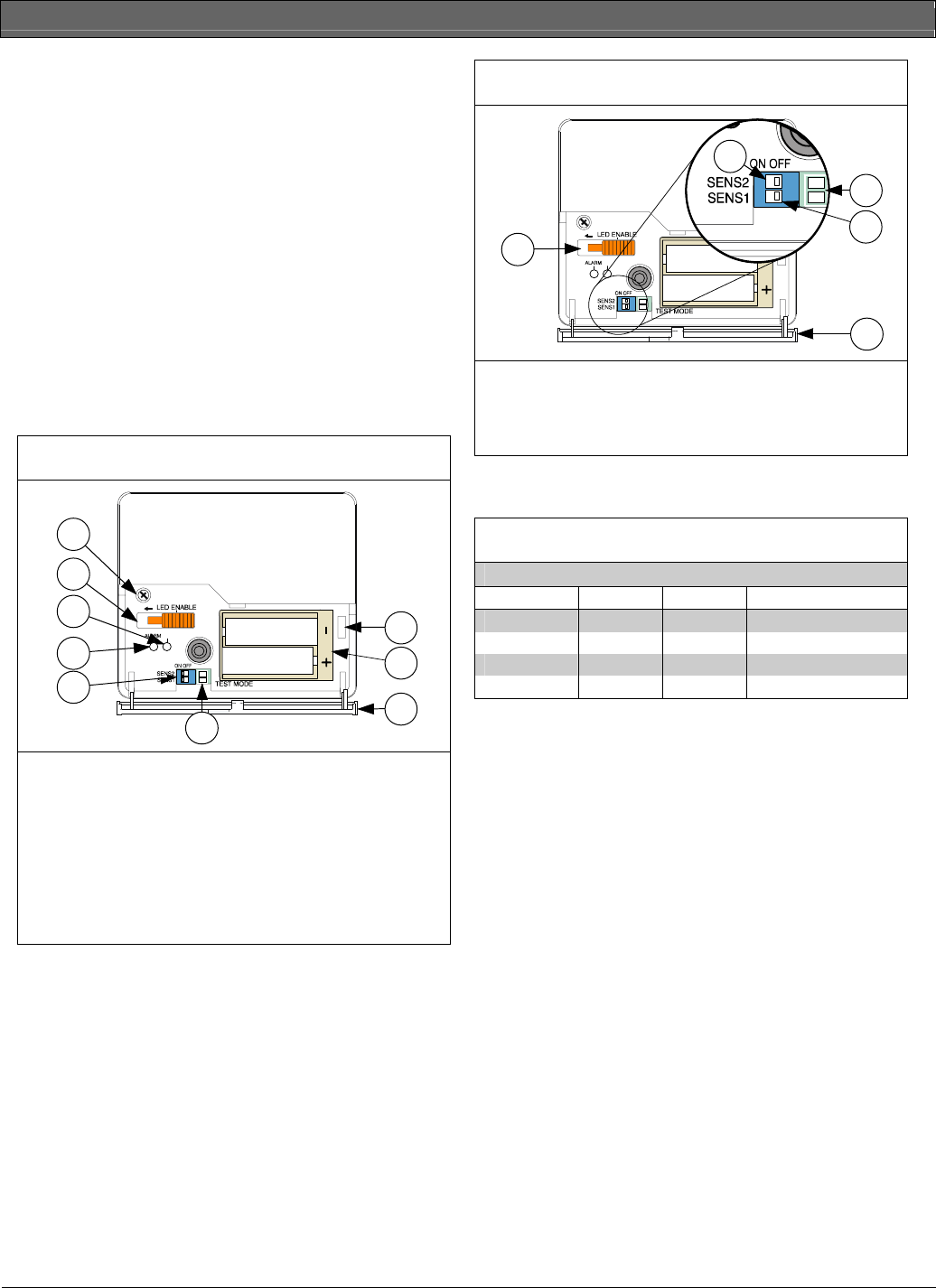
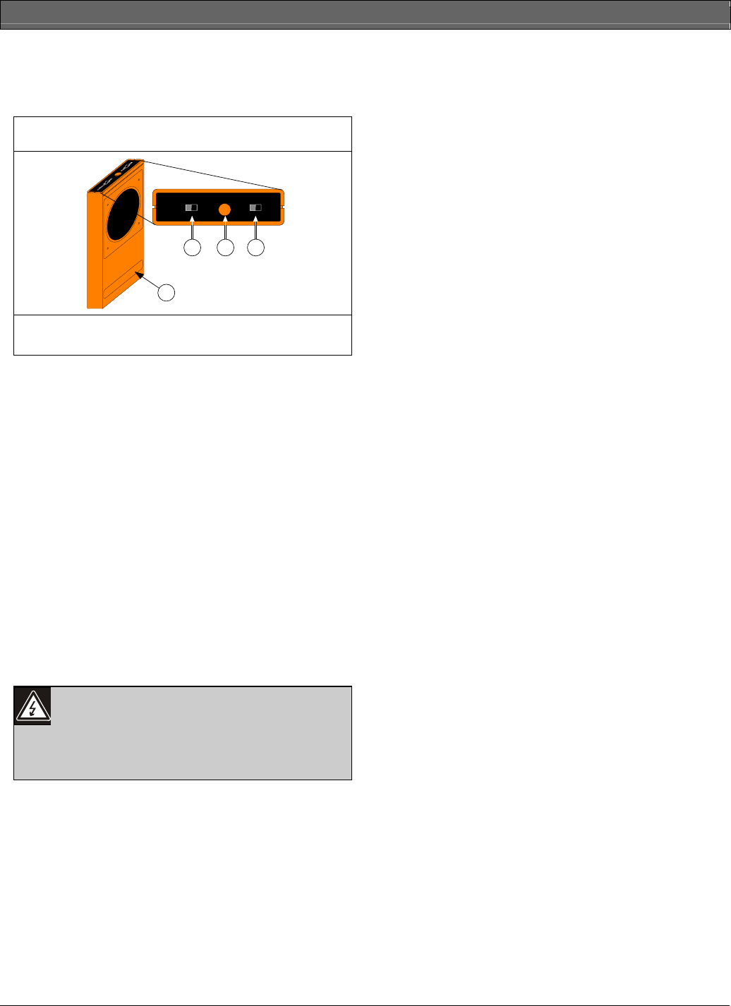
Figure 4: RF1100 Front Layout
8
9
3
5
7
61
EVENT
4
2
1 - Service door tamper
switch
2 - AA batteries
3 - Service door
4 - SW4 Test Mode
pads
5 - SW3 sensitivity DIP
switches
6 - Alarm LED
7 - Event LED
8 - LED enable switch
(off position)
9 - Housing screw
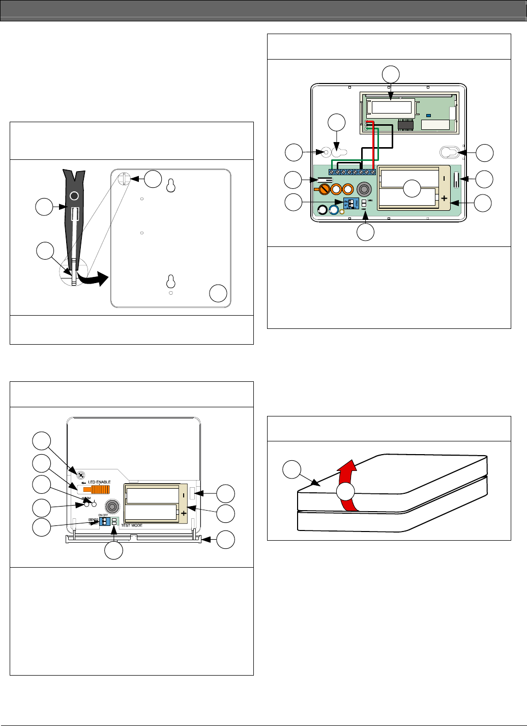
Figure 5: Sensitivity Switch
EVENT
3
2
4
5
1
1 - SENS2
2 - Test Mode pads
3 - SENS1
4 - Service door
5 - LED enable switch
(shown in the OFF
position)
3. Determine the sensitivity setting for your
application from Table 1.
Table 1: RF1100 Sensitivity Settings
Sensitivity SENS1 SENS2 Approximate Range
Maximum OFF OFF 25 ft (7.6 m)
Medium ON OFF 15 ft (4.6 m)
Low OFF ON 10 ft (3 m)
Lowest ON ON 5 ft (1.5 m)
4. Use a small flat head screwdriver to move the
sensitivity switches. Use the settings determined in
Step 3.
5. Turn on any sources of noise such as machinery,
office, or audio equipment in the area.
6. Observe the green event LED (Item 7 in Figure 4)
for approximately 1 min. If the green LED flashes,
relocate the unit or reduce the sensitivity by
adjusting the sensitivity switch.
7. Repeat Steps 3 through 6 until you achieve the best
sensitivity level.
8. After setting the sensitivity, slide the LED enable
switch (Item 5 in Figure 5) to the OFF position.
RF1100 | Installation Instructions | 2.0 Setup
.
Bosch Security Systems | 7/04 | 4998138680B 5
2.2 Testing
Test the RF1100 at least once each year. Test the
detector with the 13-332 Sound Sensor Tester.
Figure 6: 13-332 Sound Sensor Tester
1
ACTIVATE TEST FLEX MAN
2 3 4
1 - 13-332
2 - Activate/Test switch
3 - Start button
4 - Flex/Man switch
2.2.1 Entering Test Mode
Place the RF1100 in Test Mode before testing the unit.
Test Mode enables the RF1100's LED switch (Item 5 in
Figure 5 on page 4). You can enter the Test Mode
locally or remotely.
To enter the Test Mode locally:
1. Carefully open the service door of the RF1100.
2. Insert a screwdriver into the slot next to the
sensitivity switches that contains the test pads.
3. Touch both test pads at the same time with the tip
of the screwdriver.
The green LED (Item 7 in Figure 4 on page 4) on the
RF1100 flashes once per second. If the green LED does
not flash, repeat Steps 2 and 3.
You can select the glass break sensitivity remotely from
a Bosch 13-332 Sound Sensor Tester to activate a Test
Mode.
The 13-332 Sound Sensor Tester
produces extremely loud sounds and can
be hazardous to hearing when used at
close range. Do not point the 13-332
towards someone’s head.
To enter the Test Mode remotely:
1. Stand within 9 ft (3 m) of the RF1100.
2. Move the switches on top of the 13-332 tester to
ACTIVATE (Item 2 in Figure 6) and MAN (Item 4,
Figure 6) Modes.
3. Point the front of the tester towards the detector
and press the red Start button (Item 3 in Figure 6).
The tester buzzes and the green LED on the RF1100
flashes once per second. If the green LED does not
flash, move closer to the detector and repeat the
procedure.
2.2.2 Testing the Detector (Flex and Audio
Signals)
1. Set the 13-332 tester switches to the TEST (Item 2
in Figure 6) and FLEX positions (Item 4 in Figure 6).
2. Press the red Start button (Item 3 in Figure 6). The
tester activates and starts an eight-second armed
period.
3. If window coverings are present, close them fully.
4. Hold the 13-332 tester near the point on the glass
farthest from the detector. If window coverings are
present, hold the tester between the glass and
window coverings.
5. Carefully strike the glass with a cushioned tool.
The 13-332 tester responds by producing a burst of
glass break audio.
If the RF1100 receives both the flex and audio signals
properly, its red Alarm LED lights for 3 sec.
If the red LED does not light, return to Step 2 in Section
2.0 Setup on page 4 to reposition the detector.
2.2.3 Exiting Test Mode
To exit the Test Mode locally:
1. Carefully open the service door of the RF1100.
2. Insert a screwdriver into the slot next to the
sensitivity switches that contains the test pads.
3. Touch both test pads at the same time with the tip
of the screwdriver.
When the detector exits Test Mode, the green LED
(Item 7 in Figure 4 on page 4) on the RF1100 stops
flashing. If the green LED continues to flash, repeat
Steps 2 and 3.
To exit the Test Mode remotely:
1. Stand within 9 ft (3 m) of the detector.
2. Move the switches on top of the 13-332 tester to
ACTIVATE (Item 2 in Figure 6) and MAN (Item 4,
Figure 6) Modes.
3. Point the front of the tester towards the detector
and press the red Start button (Item 3 in Figure 6).
4. The tester buzzes.
RF1100 | Installation Instructions | 3.0 Mounting the RF1100
6 Bosch Security Systems | 7/04 | 4998138680B
2.3 Enabling the Wall Tamper
Using the wall tamper is optional. To enable the wall
tamper:
• Use needle-nose pliers to remove the plastic tab on
the back of the detector (Figure 7). The wall tamper
contact extends through the hole.
Figure 7: Removing the Wall Tamper Plastic Tab
Block
3
1
2
4
1 - Needle-nose pliers
2 - Plastic tab
3 - Back of RF1100
4 - Tamper contact
3.0 Mounting the RF1100
Figure 8: RF1100 Front Layout
8
9
3
5
7
61
EVENT
4
2
1 - Service door tamper
switch
2 - AA batteries
3 - Service door
4 - SW4 Test Mode
pads
5 - SW3 sensitivity DIP
switches
6 - Alarm LED
7 - Event LED
8 - LED enable switch
(OFF position)
9 - Housing screw
Figure 9: RF1100 Inside Layout
2
2
4
4
5
7
8
3
6
ID:000000000
RF1100
1
1 - RF ID sticker
2 - Mounting holes
3 - Front housing
screw hole
4 - Front housing
tamper switch
5 - Sensitivity switches
6 - Test Mode pads
7 - AA alkaline
batteries
8 - Battery housing
1. Open the service door (Item 3 in Figure 8).
2. Remove the housing screw (Item 9 in Figure 8)
located near the LED ENABLE switch (Item 8 in
Figure 8).
3. Lift the end of the cover off the base near the
housing screw (Item 9 in Figure 8 and Figure 10).
Figure 10: Removing the Cover
1
2
1 - RF1100 Cover 2 - Direction of removal
4. Use the mounting template (Figure 1 on page 2) to
mark the mounting holes and tamper screw hole
(optional) on the mounting surface.
5. Drill the holes and insert the supplied wall anchors
(if needed).
6. Partially insert the mounting screws and tamper
screw (optional) into the mounting surface.
7. Place the base over the screws and slide it down.
8. If the optional wall tamper is used, adjust the
tamper screw so it just touches the tamper contact
and the base is flat against the mounting surface
(Item 4 in Figure 7).
RF1100 | Installation Instructions | 4.0 Low Battery Indication
.
Bosch Security Systems | 7/04 | 4998138680B 7
9. Tighten the mounting screws to secure the unit in
place.
10. Write down the ID number of the RF ID sticker
(Item 1 in Figure 9 on page 6).
11. Align the tabs on the cover with the slots on the
base and close the cover.
12. Replace the housing screw.
13. To ensure proper detection, re-test the detector’s
sensitivity. Refer to Section 2.1 Sensitivity Setting and
Section 2.2 Testing on page 5.
4.0 Low Battery Indication
The RF1100 indicates a low battery condition in two
ways:
• If the LEDs are enabled, both flash simultaneously
every second.
• During each transmission, a battery status
indication is sent to the control panel.
The LED flashing and a low battery indication at the
control panel are independent of each other and do not
necessarily occur at the same time. Receiving either
condition indicates a low battery.
5.0 Control Panel Programming
A two-part RF ID sticker (Item 1 in Figure 9 on page 6)
is located inside the transmitter portion of the RF1100.
The number on this sticker is needed to program the
transmitter into the control panel. Refer to your control
panel’s programming guide for programming
information on wireless type devices.
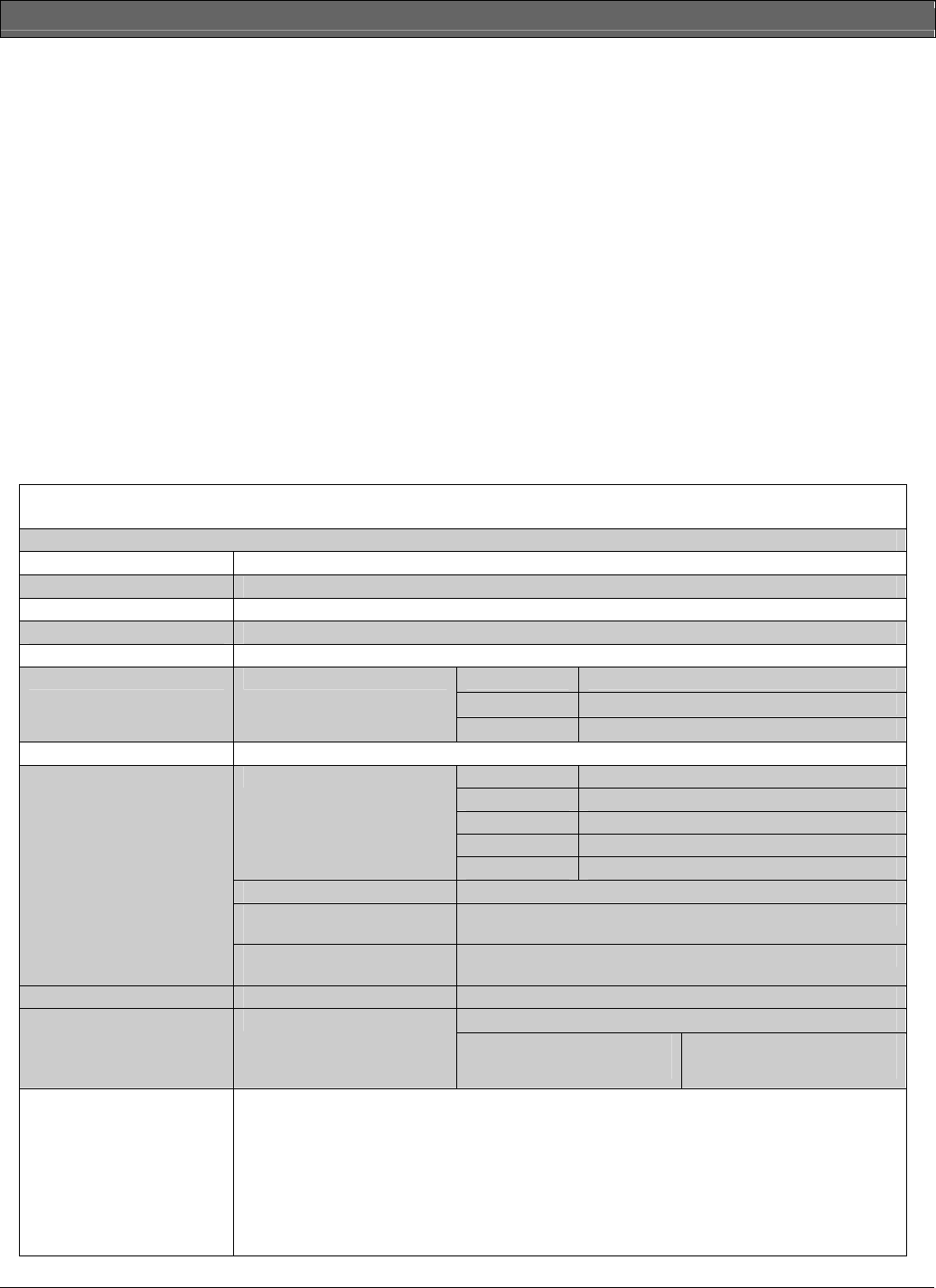
6.0 Specifications
Table 2: RF1100 Specifications
Dimensions 4.8 in. x 4.2 in. x 1.3 in. (12.2 cm x 10.6 cm x 3.2 cm)
Operating Temperature +32°F to +120°F (0°C to +50°C
Frequency 304 MHz
Operating Voltage 3 V
Battery Life At least two years under normal operating conditions. Test with the recommended battery types.
Duracell® MN1500 or PC1500
Eveready ™ E91
Recommended Battery Types Two AA Alkaline
Panasonic® AM-3PIXB
Compatible Receivers RF3212, RF3222, and RF3224
Type Thickness
Plate 0.09 in. to 0.38 in. (0.24 cm to 0.95 cm)
Tempered 0.13 in. to 0.38 in. (0.32 cm to 0.95 cm)
Laminated* 0.13 in. to 0.56 in. (0.32 cm to 1.43 cm)
Glass Types and Thicknesses
Wired: 0.25 in. (0.64 cm)
* protected only if both panes of glass are broken
Minimum pane size for all types
of glass
11 in. (28 cm) x 11 in. (28 cm)
Acoustic Capabilities
Minimum wall or barrier width
for mounting glass 3 ft (0.9 m)
Range Maximum 25 ft (7.6 m)
Use DIP switches to set sensitivity levels to reduce false alarms: Sensitivity Settings
• Maximum
• Medium
• Low
• Lowest
FCC Compliance The RF1100 Wireless Glass Break Transmitter complies with Part 15 of the FCC rules and with
RSS-210 of Industry and Science Canada.
Operation is subject to the following two conditions:
• This device cannot cause harmful interference.
• This device must accept any interference received, including interference that can cause
undesirable operation.
Changes or modifications not expressly approved by Bosch Security Systems can void the user’s
authority to operate the equipment.

© 2004 Bosch Security Systems
4998138680B
Bosch Security Systems
130 Perinton Parkway
Fairport, NY 14450-9199
Customer Service: (800) 289-0096
Technical Support: (888) 886-6189