Bosch 11255VSR User Manual ROTARY TOOL Manuals And Guides L0612117
BOSCH Power Hammer Manual L0612117 BOSCH Power Hammer Owner's Manual, BOSCH Power Hammer installation guides
User Manual: Bosch 11255VSR 11255VSR BOSCH ROTARY TOOL - Manuals and Guides View the owners manual for your BOSCH ROTARY TOOL #11255VSR. Home:Tool Parts:Bosch Parts:Bosch ROTARY TOOL Manual
Open the PDF directly: View PDF ![]() .
.
Page Count: 32

IMPORTANT: IMPORTANT: IMPORTANTE:
Read Before Using Lireavantusage Leerantesde usar
Operating/SafetyInstructions
Consignesdefonctionnement/s6curit6
Instruccionesdefuncionamientoyseguridad
11253VSR
11255VSR
BOSCH
Call Toll Free
forConsumerInformation
& ServiceLocations
Pourrenseignementdes
consommateursetcentres
de service, appelezau
num_rogratuit:
Llamegratispara
obtenerinformaci6n
para el consumidory
ubicacionesde servicio
For English Parlez-vousfran_ais? _,Hablaespafiol?
See page 2 Voir page11 Ver p_gina20

General Safety Rules
_Read all instructions. Failure to follow all instructions listed below may
result in electric shock, fire and/or serious injury. The term "power tool" in
all of the warnings listed below refers to your mains-operated (corded) power tool or battery-
operated (cordless) power tool.
SAVE THESE INSTRUCTIONS
Work area safety
Keep work area clean and well lit.
Cluttered or dark areas invite accidents.
Do not operate power tools in explosive
atmospheres, such as in the presence of
flammable liquids, gases or dust. Power
tools create sparks which may ignite the dust
or fumes.
Keep children and bystanders away while
operating a power tool. Distractions can
cause you to lose control.
Electrical safety
Power tool plugs must match the outlet.
Never modify the plug in any way. Do not
use any adapter plugs with earthed
(grounded) power tools. Unmodified plugs
and matching outlets will reduce risk of
electric shock.
Avoid body contact with earthed or
grounded surfaces such as pipes,
radiators, ranges and refrigerators. There
is an increased risk of electric shock if your
body is earthed or grounded.
Do not expose power tools to rain or wet
conditions. Water entering a power tool will
increase the risk of electric shock.
Do not abuse the cord. Never use the cord
for carrying, pulling or unplugging the
power tool. Keep cord away from heat, oil,
sharp edges or moving parts. Damaged or
entangled cords increase the risk of electric
shock.
When operating a power tool outdoors,
use an extension cord suitable for
outdoor use. Use of a cord suitable for
outdoor use reduces the risk of electric
shock.
Do not use AC only rated tools with a DC
power supply. While the tool may appear to
work, the electrical components of the AC
rated tool are likely to fail and create a
hazard to the operator.
If operating the power tool in damp
locations is unavoidable a Ground Fault
Circuit Interrupter (GFCI) must be used to
supply the power to your tool. GFCI and
personal protection devices like electrician's
rubber gloves and footwear will further
enhance your personal safety.
Personal safety
Stay alert, watch what you are doing and
use common sense when operating a
power tool. Do not use a power tool while
you are tired or under the influence of
drugs, alcohol or medication. A moment of
inattention while operating power tools may
result in serious personal injury.
Use safety equipment. Always wear eye
protection. Safety equipment such as dust
mask, non-skid safety shoes, hard hat, or
hearing protection used for appropriate
conditions will reduce personal injuries.
Avoid accidental starting. Ensure the
switch is in the off-position before
plugging in. Carrying power tools with your
finger on the switch or plugging in power
tools that have the switch on invites
accidents.
Remove any adjusting key or wrench
before turning the power tool on. Awrench
or a key left attached to a rotating part of the
power tool may result in personal injury.
Do not overreach. Keep proper footing
and balance at all times. This enables
better control of the power tool in unexpected
situations.
Dress properly. Do not wear loose
clothing or jewelry. Keep your hair,
clothing and gloves away from moving
parts. Loose clothes, jewelry or long hair can
be caught in moving parts.
If devices are provided for the connection
of dust extraction and collection facilities,
ensure these are connected and properly
used. Use of these devices can reduce dust-
related hazards.
-2-

Keep handles dry, clean and free from oil
and grease. Slippery hands cannot safely
control the power tool.
Power tool use and care
Do not force the power tool. Use the
correct power tool for your application.
The correct power tool will do the job better
and safer at the rate for which it was
designed.
Do not use the power tool if the switch
does not turn it on and off. Any power tool
that cannot be controlled with the switch is
dangerous and must be repaired.
Disconnect the plug from the power
source and/or the battery pack from the
power tool before making any
adjustments, changing accessories, or
storing power tools. Such preventive safety
measures reduce the risk of starting the
power tool accidentally.
Store idle power tools out of the reach of
children and do not allow persons
unfamiliar with the power tool or these
instructions to operate the power tool.
Power tools are dangerous in the hands of
untrained users.
Maintain power tools. Check for
misalignment or binding of moving parts,
breakage of parts and any other condition
that may affect the power tools operation.
If damaged, have the power tool repaired
before use. Many accidents are caused by
poorly maintained power tools.
Keep cutting tools sharp and clean.
Properly maintained cutting tools with sharp
cutting edges are less likely to bind and are
easier to control.
Use the power tool, accessories and tool
bits etc., in accordance with these
instructions and in the manner intended
for the particular type of power tool,
taking into account the working
conditions and the work to be performed.
Use of the power tool for operations different
from those intended could result in a
hazardous situation.
Use clamps or other practical way to
secure and support the workpiece to a
stable platform. Holding the work by hand
or against your body is unstable and may
lead to loss of control.
Service
Have your power tool serviced by a
qualified repair person using only identical
replacement parts. This will ensure that the
safety of the power tool is maintained.
Develop a periodic maintenance schedule
for your tool. When cleaning a tool be
careful not to disassemble any portion of
the tool since internal wires may be
misplaced or pinched or safety guard
return springs may be improperly
mounted. Certain cleaning agents such as
gasoline, carbon tetrachloride, ammonia, etc.
may damage plastic parts.
Rotary Hammer Safety Rules
Hold tools by insulated gripping surfaces
when performing an operation where the
cutting tool may contact hidden wiring or
its own cord. Contact with a "live" wire will
make exposed metal parts of the tool "live" and
shock the operator. Do not drill, fasten or break
into existing walls or other blind areas where
electrical wiring may exist. If this situation is
unavoidable, disconnect aft fuses or circuit
breakers feeding this worksite.
Wear ear protectors when using the tool for
extended periods. Prolonged exposure to
high intensity noise can cause hearing loss.
Use a metal detector to determine if there
are gas or water pipes hidden in the work
area or call the local utility company for
assistance before beginning the operation.
Striking or cutting into a gas line will result in
explosion. Water entering an electrical device
may cause electrocution.
Always use the side handle for maximum
control over torque reaction or kick-back.
Never attempt to operate this tool with one
hand. The slip clutch engages if you firmly
control the tool during a torque reaction or
kickback.
Always wear safety goggles or eye
protection when using this tool. Use a dust
mask or respirator for applications which
generate dust. Safety goggles or eye
-3-
protection will help deflect fragments of the
material that may be thrown toward your face
and eyes. Dust generated or gases released
from the material you are cutting (i.e. asbestos
insulated pipes, radon) may cause respiratory
difficulties.
Use thick cushioned gloves and limit the
exposure time by taking frequent rest
periods. Vibration caused by hammer-drill
action may be harmful to your hands and
arms.
Position the cord clear of rotating bit. Do
not wrap the cord around your arm or wrist.
If cord becomes entangled with the spinning bit
it could entrap you causing serious personal
injury.
Position yourself to avoid being caught
between the tool or side handle and walls
or posts. Should the bit become bound or
jammed in the work, the reaction torque of
the tool could crush your hand or leg.
Do not strike the bit with a handheld
hammer or sledge hammer when
attempting to dislodge a bound or jammed
bit. Fragments of metal from the bit could
dislodge and strike you or bystanders.
Never place the tool down until the bit or
accessory have come to a complete stop.
Do not use dull or damaged bits and
accessories. Dull or damaged bits have a
greater tendency to bind in the workpiece.
When removing the bit from the tool avoid
contact with skin and use proper protective
gloves when grasping the bit or accessory.
Accessories may be hot after prolonged use.
Do not run the tool while carrying it at your
side. The spinning drill bit may become
entangled with clothing and injury may result.
I__1 Some dust created by
power sanding, sawing,
grinding, drilling, and other construction
activities contains chemicals known to
cause cancer, birth defects or other
reproductive harm. Some examples of
these chemicals are:
•Lead from lead-based paints,
• Crystalline silica from bricks and cement
and other masonry products, and
• Arsenic and chromium from chemically-
treated lumber.
Your risk from these exposures varies,
depending on how often you do this type of
work. To reduce your exposure to these
chemicals: work in a well ventilated area, and
work with approved safety equipment, such
as those dust masks that are specially
designed to filter out microscopic particles.
-4-
Symbols
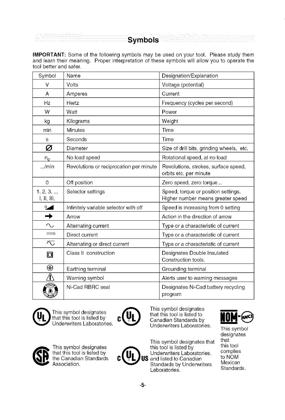
IMPORTANT: Some of the following symbols may be used on your tool. Please study them
and learn their meaning. Proper interpretation of these symbols will allow you to operate the
tool better and safer.
Symbol Name
V Volts
A Amperes
Hz Hertz
W Watt
kg Kilograms
rain Minutes
s Seconds
O Diameter
n o No load speed
Designation/Explanation
Voltage (potential)
Current
Frequency (cycles per second)
Power
Weight
Time
Time
Size of drill bits, grinding wheels, etc.
Rotational speed, at no load
.../rain Revolutions or reciprocation per minute Revolutions, strokes, surface speed,
orbits etc. per minute
0 Off position Zero speed, zero torque...
1,2, 3 .... Selector settings Speed, torque or position settings.
I, II, Ill, Higher number means greater speed
Infinitely variable selector with off Speed is increasing from 0 setting
Arrow Action in the direction of arrow
Alternating current Type or a characteristic of current
--_ Direct current Type or a characteristic of current
"%, Alternating or direct current Type or a characteristic of current
[] Class II construction Designates Double Insulated
Construction tools.
(_) Earthing terminal Grounding terminal
Warning symbol Alerts user to warning messages
Ni-Cad RBRC seal Designates Ni-Cad battery recycling
program
This symbol designates
that this tool is listed by
Underwriters Laboratories.
_[ his symbol designates
that this tool is listed by
the Canadian Standards
Association.
This symbol designates W_
that this tool is listed to
CCanadian Standards by
Underwriters Laboratories. This symbol
designates
This symbol designates that that
this tool is listed by this tool
Underwriters Laboratories, complies
C US and listed to Canadian to NOM
Standards by Underwriters Mexican
Laboratories. Standards.
-5-
Functional Description and Specifications
_isconnect the plug from the power source before making any assembly,
adjustments or changing accessories. Such preventive safety measures
reduce the risk of starting the tool accidentally.
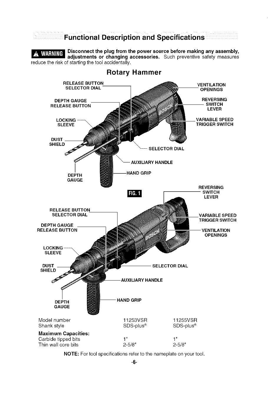
Rotary Hammer
RELEASE BUTTON VENTILATION
SELECTOR DIAL OPENINGS
DEPTH GAUGE REVERSING
RELEASE BUTTON SWITCH
LEVER
LOCKING_
SLEEVE "_
VARIABLE SPEED
TRIGGER SWITCH
SHIELD
I
DEPTH
GAUGE
RELEASE BUTTON
SELECTOR DIAL
DEPTH GAUGE
RELEASE BUTTON
LOCKING_
SLEEVE'_
DUST __
SHIELD
SELECTOR DIAL
_AUXILIARY HANDLE
REVERSING
m SWITCH
LEVER
.VARIABLE SPEED
TRIGGER SWITCH
VENTILATION
OPENINGS
SELECTOR DIAL
DEPTH
GAUGE
Model number 11253VSR 11255VSR
Shank style SDS-plus ® SDS-plus ®
Maximum Capacities:
Carbide tipped bits 1" 1"
Thin wall core bits 2-5/8" 2-5/8"
NOTE: For tool specifications refer to the nameplate on your tool.
"6"
Operating Instructions
VARIABLE SPEED CONTROLLED
TRIGGER SWITCH
Your tool is equipped with a variable speed
trigger switch. The tool speed can be
controlled from the minimum to the maximum
nameplate RPM by the pressure you apply to
the trigger. Apply more pressure to increase
the speed and release pressure to decrease
speed. This accurate speed control enables
you to drill without center punching. It also
permits you to use as a power screwdriver.
Bits are available for driving screws as well
as running bolts and nuts.
REVERSING SWITCH LEVER
This tool is equipped with a rotating brush
reversing system. This results in longer brush
life while maximizing power in both forward and
reverse directions. The reverse switch can be
operated from either the right or left side of the
tool.
FOR FORWARD ROTATION: slide switch to
arrow marked forward (Fig. 1).
FOR REVERSE ROTATION: slide the slide
switch to arrow marked reverse. NOTE: Tool
will not operate in middle position.
SLIP CLUTCH
The tool has an internal preset clutch. The
clutch is set such that sufficient force is
transmitted to the bit for most drilling
conditions but it will slip when bit binds in the
hole or the tool is overloaded. Be aware that
due to required clutch setting, you may
experience a torque reaction an instant
before the clutch slips. This torque reaction
will twist the body of the rotary hammer in the
opposite direction as the bit rotates, i.e.,
counterclockwise. As clutch is slipping, the
bit will most likely stop rotating. When the
binding force on the bit is removed the clutch
automatically resets. If you experience bit
binding and clutch begins to slip, immediately
turn the tool "OFF" and correct the condition
leading to the bit binding.
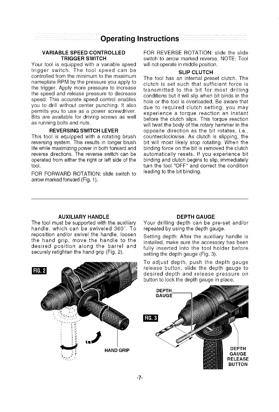
AUXILIARY HANDLE
The tool must be supported with the auxiliary
handle, which can be swiveled 360 °. To
reposition and/or swivel the handle, loosen
the hand grip, move the handle to the
desired position along the barrel and
securely retighten the hand grip (Fig. 2).
HAND GRIP
DEPTH GAUGE
Your drilling depth can be pre-set and/or
repeated by using the depth gauge.
Setting depth: After the auxiliary handle is
installed, make sure the accessory has been
fully inserted into the tool holder before
setting the depth gauge (Fig. 3).
To adjust depth, push the depth gauge
release button, slide the depth gauge to
desired depth and release pressure on
button to lock the depth gauge in place.
DEPTH
GAUGE
DEPTH
GAUGE
RELEASE
BUTTON
-7-
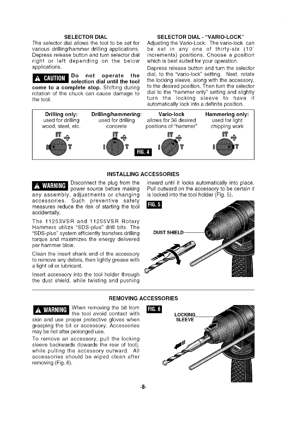
SELECTOR DIAL
The selector dial allows the tool to be set for
various drilling/hammer drilling applications.
Depress release button and turn selector dial
right or left depending on the below
applications.
I__Do not operate the
selection dial until the tool
come to a complete stop. Shifting during
rotation of the chuck can cause damage to
the tool.
SELECTOR DIAL - "VARIO-LOCK"
Adjusting the Vario-Lock: The vario-lock can
be set in any one of thirty-six (10 °
increments) positions. Choose a position
which is best suited for your operation.
Depress release button and turn the selector
dial, to the "vario-lock" setting. Next, rotate
the locking sleeve, along with the accessory,
to the desired position. Then turn the selector
dial to the "hammer only" setting and slightly
turn the locking sleeve to have it
automatically lock into a definite position.
Drilling only: Drilling/hammering: Vario-lock Hammering only:
used for drilling used for drilling allows for 36 desired used for light
wood, steel, etc. concrete positions of "hammer" chipping work
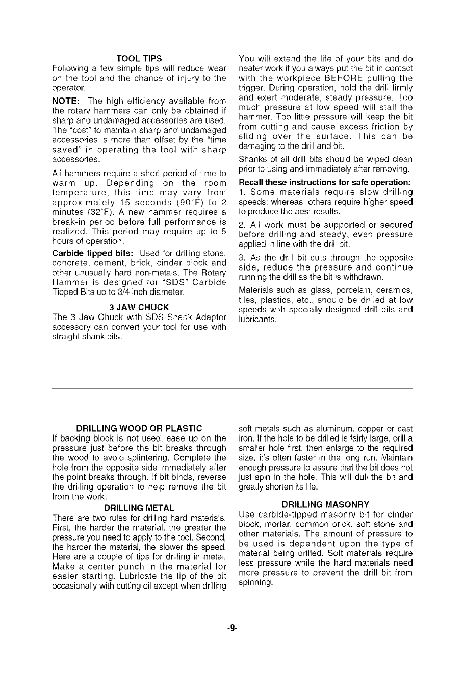
INSTALLING ACCESSORIES
_ Disconnect the plug from the
power source before making
any assembly, adjustments or changing
accessories. Such preventive safety
measures reduce the risk of starting the tool
accidentally.
The 11253VSR and 11255VSR Rotary
Hammers utilize "SDS-plus" drill bits. The
"SDS-plus" system efficiently transfers drilling
torque and maximizes the energy delivered
per hammer blow.
Clean the insert shank end of the accessory
to remove any debris, then lightly grease with
a light oil or lubricant.
Insert accessory into the tool holder through
the dust shield, while twisting and pushing
inward until it locks automatically into place.
Pull outward on the accessory to be certain it
is locked into the tool holder (Fig. 5).
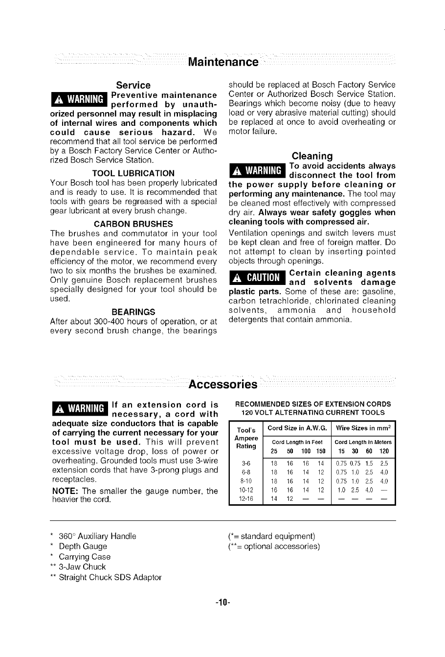
REMOVING ACCESSORIES
When removing the bit from
the tool avoid contact with
skin and use proper protective gloves when
grasping the bit or accessory. Accessories
may be hot after prolonged use.
To remove an accessory, pull the locking
sleeve backwards (towards the rear of tool),
while pulling the accessory outward. All
accessories should be wiped clean after
removing (Fig. 6).
WLOCKING
SLEEVE
-8-
TOOL TIPS
Following a few simple tips will reduce wear
on the tool and the chance of injury to the
operator.
NOTE: The high efficiency available from
the rotary hammers can only be obtained if
sharp and undamaged accessories are used.
The "cost" to maintain sharp and undamaged
accessories is more than offset by the "time
saved" in operating the tool with sharp
accessories.
All hammers require a short period of time to
warm up. Depending on the room
temperature, this time may vary from
approximately 15 seconds (90°F) to 2
minutes (32°F). A new hammer requires a
break-in period before full performance is
realized. This period may require up to 5
hours of operation.
Carbide tipped bits: Used for drilling stone,
concrete, cement, brick, cinder block and
other unusually hard non-metals. The Rotary
Hammer is designed for "SDS" Carbide
Tipped Bits up to 3/4 inch diameter.
3 JAW CHUCK
The 3 Jaw Chuck with SDS Shank Adaptor
accessory can convert your tool for use with
straight shank bits.
You will extend the life of your bits and do
neater work if you always put the bit in contact
with the workpiece BEFORE pulling the
trigger. During operation, hold the drill firmly
and exert moderate, steady pressure. Too
much pressure at low speed will stall the
hammer. Too little pressure will keep the bit
from cutting and cause excess friction by
sliding over the surface. This can be
damaging to the drill and bit.
Shanks of all drill bits should be wiped clean
prior to using and immediately after removing.
Recall these instructions for safe operation:
1. Some materials require slow drilling
speeds; whereas, others require higher speed
to produce the best results.
2. All work must be supported or secured
before drilling and steady, even pressure
applied in line with the drill bit.
3. As the drill bit cuts through the opposite
side, reduce the pressure and continue
running the drill as the bit is withdrawn.
Materials such as glass, porcelain, ceramics,
tiles, plastics, etc., should be drilled at low
speeds with specially designed drill bits and
lubricants.
DRILLING WOOD OR PLASTIC
If backing block is not used, ease up on the
pressure just before the bit breaks through
the wood to avoid splintering. Complete the
hole from the opposite side immediately after
the point breaks through. If bit binds, reverse
the drilling operation to help remove the bit
from the work.
DRILLING METAL
There are two rules for drilling hard materials.
First, the harder the material, the greater the
pressure you need to apply to the tool. Second,
the harder the material, the slower the speed.
Here are a couple of tips for drilling in metal.
Make a center punch in the material for
easier starting. Lubricate the tip of the bit
occasionally with cutting oil except when drilling
soft metals such as aluminum, copper or cast
iron. If the hole to be drilled is fairly large, drill a
smaller hole first, then enlarge to the required
size, it's often faster in the long run. Maintain
enough pressure to assure that the bit does not
just spin in the hole. This will dull the bit and
greatly shorten its life.
DRILLING MASONRY
Use carbide-tipped masonry bit for cinder
block, mortar, common brick, soft stone and
other materials. The amount of pressure to
be used is dependent upon the type of
material being drilled. Soft materials require
less pressure while the hard materials need
more pressure to prevent the drill bit from
spinning.
-g.
Service
_Preventive maintenance
performed by unauth-
orized personnel may result in misplacing
of internal wires and components which
could cause serious hazard. We
recommend that all tool service be performed
by a Bosch Factory Service Center or Autho-
rized Bosch Service Station.
TOOL LUBRICATION
Your Bosch tool has been properly lubricated
and is ready to use. It is recommended that
tools with gears be regreased with a special
gear lubricant at every brush change.
CARBON BRUSHES
The brushes and commutator in your tool
have been engineered for many hours of
dependable service. To maintain peak
efficiency of the motor, we recommend every
two to six months the brushes be examined.
Only genuine Bosch replacement brushes
specially designed for your tool should be
used.
BEARINGS
After about 300-400 hours of operation, or at
every second brush change, the bearings
should be replaced at Bosch Factory Service
Center or Authorized Bosch Service Station.
Bearings which become noisy (due to heavy
load or very abrasive material cutting) should
be replaced at once to avoid overheating or
motor failure.
Cleaning
I__1 To avoid accidents always
disconnect the tool from
the power supply before cleaning or
performing any maintenance. The tool may
be cleaned most effectively with compressed
dry air. Always wear safety goggles when
cleaning tools with compressed air.
Ventilation openings and switch levers must
be kept clean and free of foreign matter. Do
not attempt to clean by inserting pointed
objects through openings.
I__ Certain cleaning agents
and solvents damage
plastic parts. Some of these are: gasoline,
carbon tetrachloride, chlorinated cleaning
solvents, ammonia and household
detergents that contain ammonia.
If an extension cord is
necessary, a cord with
adequate size conductors that is capable
of carrying the current necessary for your
tool must be used. This will prevent
excessive voltage drop, loss of power or
overheating. Grounded tools must use 3-wire
extension cords that have 3-prong plugs and
receptacles.
NOTE: The smaller the gauge number, the
heavier the cord.
RECOMMENDED SIZES OF EXTENSION CORDS
120 VOLT ALTERNATING CURRENT TOOLS
Tool's Cord Size in A.W.G. Wire Sizes in mm 2
Ampere
Rating Cord Lengthin Feet
25 50 100 150
3-6 18 16 16 14
6-8 18 16 14 12
8-10 18 16 14 12
10-12 16 16 14 12
12-16 14 12
Cord Lengthin Meters
15 30 60 120
0.75 0.75 1.5 2.5
0.75 1.0 2.5 4.0
0.75 1.0 2.5 4.0
1.0 2.5 4.0 --
* 360 ° Auxiliary Handle
* Depth Gauge
* Carrying Case
** 3-Jaw Chuck
** Straight Chuck SDS Adaptor
(*= standard equipment)
(**= optional accessories)
-10-
Veuillezlireet comprendreroutesles coesigees.Si one'observepastoutesles
consignesd_critesci-dessous,il y arisquede chocelectrique, d'incendieet/ou
deblessurescorporellesgraves.Dartstouteslesraisesengardeci-dessous,leterme<<outil _lectroportatif,,
serapporte_desoutilsbranch_ssur lesecteur(avecill) ou_ desoutilsailment,s parpiles(sansill).
CONSERVEZCESCONSIGNES
S_curit_dulieudetravail
Maintenez le lieu de travail propre et bien eclair&
Les risques d'accident sont plus _lev_s quand on
travaille dans un endroit encombrd ou sombre.
N'utilisez pas d'outils _lectrepertatifs dans des
atmospheres explosives, comme par exemple en
presence de gaz, de poussi_res ou de liquides
inflammables. Les outils _lectroportatits produisent
des _tincelles qui risquent d'enflammer les poussi_res
ou lesvapeurs.
I_loignezles enfantsel les visiteurs quand vousvous
servez d'un outil electroportatif. Vous risquez une
perte de contr61esi on vous distrait.
S_curit__lectrique
Les fiches des outils electroportatifs doivent
correspondre_la prise. II ne taut absolumentjamais
modifierla fiche, N'utilisez pas d'adaptateurdeprise
avec des outils electroportatifs munis d'une fiche de
terre. Le risque de choc _lectrique est moindre si on
utilise une fiche non modifi_e sur une prise qui lui
correspond.
I_viteztout contactdu corpsavec des surfaces reli_es
la terre tels que tuyaux, radiateurs, gazinieresou
refrig_rateurs. Le risque de choc _lectrique augrnente
si votre corps est relid_ la term.
N'exposez pas les outils_lectroportatifs _ la pluie ou
I'humidit_. Side I'eau p_n_tre dans un outil
_lectroportatif, le risquede choc _lectriqueaugmente.
Ne maltraitez pas le cordon. Ne vous en servez
jamais pourtransporterI'outi[ electroportatif, pourle
tirer ou pour le d_brancher. Eloignezle cordonde la
chaleur, des huiles, des ar_tes coupantes ou des
pi_ces mobiles. Les cordons abfm_s ou emm61_s
augmentent lesrisques de choc _lectrique.
Si vous utilisez un outil _lectroportatif _ I'ext_rieur,
employezune rallonge con_;uepour I'ext_rieur. Ces
rallonges sont faites pour I'ext_rieur et r_duisent le
risquede choc _lectrique.
N'utilisez pasun outil con_;uuniquementpour le C.A,
surune alimentation en C.C, M_me si I'outilsemble
fonctionner, lescomposants _lectriques d'un outil pr_vu
pour le C.A. tomberont probablement en panne et
risquent de crier un danger pour rutilisateur.
S'il est n_cessaire d'utiliser I'outil dans un lieu
humide, il taut I'alimenter par I'interm_diaire d'un
disjoncteur differentiel de fuite _la terre (DDFT).
L'emploi d'un DDFT et de dispositifs de protection
personnelle tels que gants et chaussures d'dlectricien
encaoutchouc am_liorent votre sdcuritd personnelle.
S_curit_personnelle
Restez concentr_, faites attention _ ce que vous
faites, et servez-vousde votrehoe sens]orsquevous
utilisez un outil _lectroportatif. N'employez pas
d'outils electroportatifs quand vous _tes fatigue ou
sous I'emprise de drogues, d'alcool ou de
m_dicaments. Quand on utilise des outils
_lectroportatifs, ilsuffit d'un moment d'inattention pour
causerdes blessurescorporelles graves
Utilisezdes_quipements de s_curit& Portez toujours
une protection oculaire. Si les conditions le
demandent il taut porter un masque _ poussi_re, des
chaussures de sdcuritd antid_rapantes, un casque de
chantier ou une protection auditive pour rdduire le
risquede blessure corporelle,
I_vitez les demarrages intempestifs. Assurez-vous
que I'interrupteuresten position arr_t (OFF) avantde
brancherI'outil. Transporter un outil _lectroportatif
avec le doigt sur la g_chette ou le brancher quand
I'interrupteur est en position "marche" (ON) pr_sente
desrisques d'accident.
Enleveztoutes les cl_s de r_glage avant de mettre
I'outil _lectroportatif en marche. Si on laisseune cl_
sur une piece tournante de I'outil _lectroportatif, il y a
risquede blessure corporelle.
Hevouspenchez pas. Coeserveztoujoursune bonee
assise et un ben _quilibre. Ceci vous permettra de
mieux maTtriserroutil _lectroportatif dans dessituations
inattendues
Habillez-vousde mani_re appropri_e. He portez pas
de vetements amples ou de bijoux. Attachez les
cheveuxlongs. N'approchez pas lee cheveux, les
v_tements ou les gants des pi_ces en mouvement.
Lesv_tements amples les bijoux oules cheveux longs
risquent d'etre happ_s par les pi_ces en mouvement.
Si I'outil est muei de dispositifs permettant le
raccordement d'un syst_me d'aspiration et de
collecte des poussi_res, assurez-vous que ces
dispositifssont raccord_s et utilis_s correctement.
L'utilisation de ces dispositifs peut permettre de r_duire
lesdangerslids _ la poussi_re.
Maintenezles poigeees s_chesel exemptesd'huile et
degraisse. On ne pas maTtriserun outil _lectroportatif
entoute s_curit_ quand on ales mains glissantes.
-11-
Utilisation et entretien des outils
_lectroportatifs
Heforcez passurI'outil _lectroportatif, Utilisez I'outil
_lectroportatif qui convient _Io t_che _effectuer.
L'outil qui convient _ la t_che fait un rneilleur travail et
est plus sgr _ lavitesse pour lequel il a dtdcon£u.
He vous servez pas de I'outil _lectroportatif si sen
interrupteurne parvientpas&le mettreen marche ou
I'arr_ter. Tout outil _lectroportatif qui ne peut pas
_tre commandd par son interrupteur est dangereux et
doit _tre rdpar&
D_branchezla fiche de la priseou eulevezle bloc-pile
de I'outil _,lectroportatif avant tout r_glage,
changementd'accessoiresou avant de ranger I'outil
_,lectroportatif. De telles mesures de s_curit_
preventive r_duisent le risque de d_marrage internpestif
de I'outil dlectroportatif.
Rangez les outils _lectreportatifs dent vous ne veus
servezpas hers de port_edes enfants et nepermettez
pas _des personnes qui ne connaissentpas I'outil
_,lectroportatif ou qui ignorentces consignesde s'en
servir. Les outils _lectroportatifs sont dangereux dans
lesmains d'utilisateurs inexpdriment_s.
Entretenezles outils _lectroportatifs, V_rifiez que les
pi_ces mobiles sent align_es correctement et ne
coincent pas. V_rifiez qu'il e'y a pos de pi_ces
cass_es ou d'autre circonstance qui risquent
d'affecter le fonctionnementde I'outil _lectroportatif.
Si I'outil est obfm_, faites-le r_parer avant de
I'utiliser, De nombreux accidents sont causes par des
outils dlectroportatifs real entretenus,
Maiutenezles outilscoupantsaffQt_setpropres.Les
outils coupantsentretenuscorrectementet dot_sde
bordstranchantsaffgtdssont moinssusceptiblesde
coinceretsontplusfaciles_ maTtriser.
UtilisezI'outil _lectroportatil, les accessoires,les
emboutsetc. seloncesconsigneset de la maui_re
pr_vue pour chaque type porticulier d'outil
_lectroportatif entenantcomptedes conditionsde
travailet de la t_che_accomplir.L'emploid'outils
_lectroportatifspourdest_chesdiff_rentesde celles
pourlesquellesils ont_tdprdvuspeutrdsulteren une
situationdangereuse.
Utilisezdesbridesou d'autresmoyenspratiquesde
brider oude supporterla piecesuroneplate-forme
stable. Tenirla piece_ la rnainou contrelecorpsest
instableet risqueder_sulteren unepertedecontrOle.
Entretien
Faites r_parer votreoutil _lectroportatif par un agent
de service qualifi_ n'utilisant que des pi_ces de
rechangeidentiques, Ceciassure que la s_curit_ de
I'outil _lectroportatif est pr_serv_e.
Cr_ez un agenda d'entretien p_riodique pour votre
outil. Quandvous nettoyezun outil, faites attention
de n'en d_monter aucune piece car il est toujours
possible de malremonteroudepincerlesfils
internes ou de remonter incorrectementles ressorts
de rappel des capers de protection. Certains agents
de nettoyage tels que I'essence, le t_trachlorure de
carbone, I'ammoniaque, etc, risquent d'abfmer les
plastiques.
R gles de s curit concernantles marteauxrotatifs
Tenez I'outil par les surfaces isol_es de prehension
en effectuant one operation oQI'outil de coupe peut
venir en contactavec des ills dissimul_s. Le contact
avec un fil sous tension rendra _galement les pieces
m_talliques expos_esde I'outil sous tension et causera
des secousses _lectriques _ I'op_rateur, Ne percez,
fixez et ne rentrez pas dans des tours existants ou
autres endroits aveugles pouvant abriter des ills
#lectriques. Si cette situation est inevitable, d#branchez
tousles fusibles ou les disjoncteurs alimentant cesite.
Portez un serre-t_te antibruit Iorsque veus utilisez
I'outil pendantdes periodesprolong_es. L'exposition
prolong_e _ un bruit de haute intensit_ peut causer une
perteauditive.
Utilisez un d_tecteur de m_taux afin d'_tablir s'il y a
des tuyauxd'eau ou _gaz dissimul_s dansI'aire de
travail ou appelez la compagnie de service public
locale pour assistance avant de commencer
I'op_ration. Le fait de frapper une conduite de gaz ou
de couper darts celle-ci provoquera une explosion.
L'eau pdndtrant darts un appareil _lectrique peut
entrafnerune dlectrocution.
Utilisez toujours la poign_e auxiliaire pour un
contr_le maximal sur le rebond ou la r_action de
couple. Ne tentez jamais d'utiliser cet outil d'une
seule main. L'embrayage _ friction s'enclenche si vous
tenez fermement I'outil quand celui-ci subit un couple
de rdaction ou un recul brutal,
Porteztoujoursdeslunettes _ coqueslat_ralesou
deslunettesde protectionen utilisant cet outil.
Utilisezunrespirateurouun masqueantipoussi_res
pourlesapplicationsqui produisentde la poussibre.
Les lunettes de s_curit_ oula protection oculaire
permettentde d_vierles fragmentsde mat_riauqui
pourraient_treprojet_sversvotrevisageet vosyeux.
Lapoussi_reg_n_r_eou lesgazlib_r_sparlemat_riau
-12-
que vous travaillez (par ex. tuyaux _ isolation amiante.
radon) peuventcauser des difficultds respiratoires.
Utilisez des pants rembourr_s _pais et limitez le
temps d'exposition en prenant des pauses
fr_quentes. Les vibrations caus_es par I'action du
marteau-perceuse peuvent _tre nocives pour vos mains
et vos bras.
Placez le cordon _ I'_cart du loret en rotation.
N'enroulez pas le cordon autour de votre bras ou de
votrepoignet,Si vous perdez contr61eet que le cordon
s'enroule autour de votre bras ou de votre poignet, il
peut vous emprisonner et vous blesser.
Placez-vous de mani_re _ _viter d'etre pris entre
I'outil ou la poign_e lat_rale et les murs ou les
montants. Si le foret se coince ou grippe dans
I'ouvrage le couple de rdaction de routil pourrait
dcraser votre main ou votre pied,
He frappez pas le lurer avec une masse ou un
marteau _ main en tentant de d_loger un foret
gripp_ ou coinc_. Des fragments mdtalliques
pourraient se d_tacher du foret et vous frapper ou
frapper des personnes prdsentes.
He posez jamais I'outil jusqu'_ ce que le lurer ou
I'accessoirese suit arr_t_ compl_tement.
N'utilisez pas de forets et d'accessoires _mouss_s
ou endommag_s, Les forets dmoussds ou
endommagds ont tendance _ gripper dans rouvrage.
Enretirant le foret de routil, _vitez tout contactavec
la peau et utilisez des pants protecteurs appropri_s
en saisissantle foret ou I'accessoire. Lesaccessoires
peuvent _tre chauds apr_s une utilisation prolong_e
Ne laissez pas I'outil en marche tout en le portant
votrecOt_.Le foret en rotation peut s'emm_ler avec lee
v_tements et causer des blessures.
Les travaux _la machine
tel que pond;age, sciage,
meulage, perk;ageet autres travaux du b_timent
peuvent crier despoussi_rescontenantdes produits
chimiquesqui soot des causes reconnuesde cancer,
de malformation cong_nitale ou d'autres prohl_mes
reproductils. Ces produits chimiques sont, par
exemple:
•Le plumb provenant des peintures _ base de plumb,
• Les cristaux de silices provenant des briques et du
ciment et d'autres produits de ma;onnerie, et
• L'arsenic et le chrome provenant des bois trait_s
chimiquement.
Le niveau de risque dt] _ cette exposition varie avec la
frdquence de ces types de travaux. Pour rdduire
I'exposition & ces produits chimiques, il taut travailler
dans un lieu bien ventild et porter un _quipement de
s_curit_ appropri_ tel que certains masques 9 poussi_re
con;us spdcialement pour filtrer les particules
microscopiques.
-13-

BM 1619929654 10-04 10/4/04 9:32 AM _e 14
IMPORTANT : Certains des symboles suivants peuvent _tre utilis_s sur votre outil. Veuillez les dtudier et
apprendre leur signification. Une interprdtation appropride de ces symboles vous permettra d'utiliser I'outil de
fagon plus efficace et plus sgre.
Symbole Nom
V Volts
A Amperes
Hz Hertz
W Watt
kg Kilogrammes
min Minutes
s Secondes
0 DiamNre
n o
.../min
0
1,2,3 ....
I. II, III....
o_
"N.,
[]
@
A,,
@
D_signation/Explication
Tension (potentielle)
Courant
Fr_quence(cycles par seconde)
Puissance
Poids
Temps
Temps
Taille des m_chesde perceuse,meules,
etc.
Vitesse _ vide Vitesse de rotation, _ vide
Tours ou mouvement alternatif par Tours, coups, vitesse en surface, orbites,
minute etc., parminute
Position d'ar@t Vitesse z6ro, couple z6ro ...
Rdglagesdu s61ecteur Rdglagesde vitesse, de couple ou de
position. Un nombre plus dlev_ signifie
une vitesse plus grande.
Sdlecteurvariable _ Hnfini avec ar@t La vitesse augmentedepuis le @@age0
Fl_che Action dans la direction de la fl_che
Courant alternatif Type ou caractdristique du courant
Courant continu Type ou caractdristique du courant
Courant alternatif Type ou caractdristique du courant
ou continu
Construction classe II D_signedes outils construits avec double
isolation
Borne de terre Borne de mise _ la terre
Symboled'avertissement Alerte I'utilisateur aux messages
d'avertissement.
SceauNi-Cad RBRCTM Ddsignele programme de recyclage des piles
Ni-Cad.
Cesymbole signifie que cet
outil est approuvd par
Underwriters Laboratories.
Cesymbole signifie que
cet outil est approuvd
conformdment aux normes
C canadiennespar Underwriters
Laboratories, Cesymbole
signifie que
cet outil se
Cesymbole signifie que cet outil conforme aux
Cesymbole signifie que cet j_, est approuv_ par Underwriters normes
outil est approuvd par _ Laboratories et qu'il a dtd mexicaines
I'Association canadienne de C US homologu_ selon les normes NOM.
normalisation, canadiennes par Underwriters
Laboratories.
-14-

Descriptionfonctionnelleet specifications
_ 6branchez la fiche de la prise de coorantavant d'effectuerquelque assemblageou
r_glage que ce soit ou de changer les accessoires. Ces mesures de sdcuritd
preventive rdduisent le risque d'une raiseen marcheaccidentellede I'outil,
Marteau rotatif
BOUTONDE
DI_CLENCREMENT PRISESD'AIR
BOUTONDEBLOCAGEDELA
BUTI_EDEPROFONDEUR LEVIERDE
D'INVERSIONDEMARCRE
MANCHONDE_
VERROUILLAGE_
I
BUT[_EDE
PROFONDEUR
CADRANSCLECTEUR
POIGN[_EAUXILIAIRE
(PRISE)
rmm
GACHETTEDE
COMMANDEA
VITESSEVARIABLE
LEVIERDE
L'INTERRUPTEUR
D'INVERSIONDE
MARCHE
BOUTONDE
DECLENCHEMENT
BOUTONDEBLOCAGEDELA
BUTEEDE PROFONDEUR
G#,CHETTEDE
COMMANDE,_
VITESSEVARIABLE
PRISESD'AIR
MANCHOND[
VERROUILLAGE
POUSSIERE CADRANSELECTEUR
BUTEEDE
PROFONDEUR
(PRISE)
Numdro de module 11253VSR 11255VSR
Type de tige SDS-plus® SDS-plus®
Capacit_smaximales :
M_ches _ pointe au carbure (26ram) (26turn)
M_ches creuses _ paroi mince (68ram) (68ram)
REMARQUE: PourspecificationsdeI'outil,reportez-vous_.laplaquesignal_tiquedevotreoutil.
-15-
GACHETTEDE COIVIIVIANDEA VITESSEVARIABLE
Votre outil est dquipd d'une ggchette _ vitesse variable,
La vitesse de I'outil peut atre contr61_e du rdgime
minimum au r_gime maximum sp_cifi_s sur la plaque
signal_tiqoe par la pression que vous exercez sur la
g_chette. Exercezplus de pression pour augmenter la
vitesse et rel_chez la pression pour diminuer la vitesse.
Cette commande precise de la vitesse vous permet de
percer sans poingonnage central. Elle vous permet
_galement d'utiliser I'outil comme tournevis _lectrique.
Des forets sont offerts pour enfoncer des vis aussi bien
que pour tourner des boulons etdes _crous.
LEVIERDEL'INTERRUPTEUR
D'INVERSIONDE MARCHE
Cet outil est pourvu du syst_rne inversion de marche
des brosses rotatives. Ce syst_me prolonge la vie utile
tout en optimalisant la puissance en marches avant et
arri_re. Cet interrupteur d'inversion peut _tre actionn_
depuis le c6t_droit ou gauche de I'outih
POURLA ROTATIONAVANT: faitesglisser I'interrupteur
jusqu'_ latl_che marq@e <<forward ,, (Fig.1).
POUR LA ROTATION INVERSE : faites glisser
I'ieterrupteur jusqu'9 la fl_che marqude <<reverse ,,.
REMARQUE : I'outil ne fonctionnera pas en position
interm_diaire.
EMBRAYAGE._ GLISSEMENT
L'outil poss_de un embrayage interne pr_r_gl_.
L'embrayage est rdgld de mani_re _ ce qu'une force
suffisante soit transmise _ la m_che pour la plupart des
conditions de per_age,mais il glissera Iorsque la meche
grippe darts le trou ou que I'outil est surchargd.Sachez
qu'en raison du rdglage requis de I'embrayage, vous
pouvez _tre confrontal & une r_action de couple un
instant avant que I'embrayage ne glisse. Cette rdaction
de couple tordra le corps du marteau rotatif darts le
sens opposd _ celui de la rotation de la m_che, ) savoir,
en sens anti-horaire. _, mesure que I'embrayage
glissera, la m_che cessera fort probablement de
tourner. Lorsque la force de grippage est retirde de la
m_che, I'embrayage se remet automatiquement _ sa
position initiale. Si vous faites I'expdrience d'un
grippage de la m_che et que I'embrayagecommence
glisser, mettez imm_diatement I'outil _ I'arr_t ,,OFF,,et
corrigez la condition menantau grippage de la m_che.
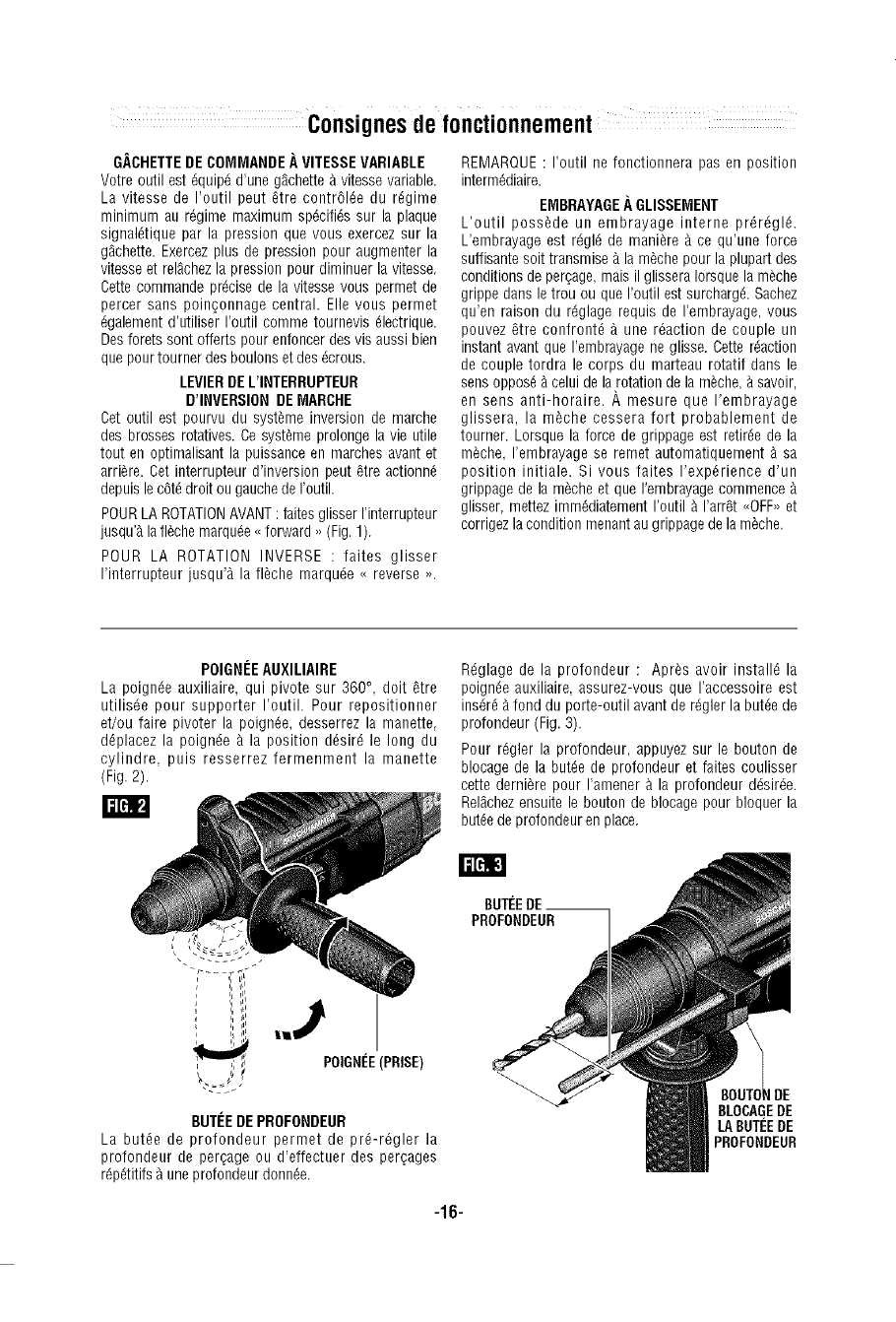
POIGNEEAUXILIAIRE
La poigede auxiliaire, qui pivote sur 360 °, doit _tre
utilisde pour supporter I'outih Pour repositionner
et/ou faire pivoter la poign_e, desserrez la manette,
ddplacez la poignde _ la position ddsird le long du
cylindre, puis resserrez fermenment la manette
(Fig. 2).
rmm
BUTEEDEPROFONDEUR
La butde de profondeur permet de prd-r_glerla
profondeur de per_age ou d'effectuer des perqages
r_pdtitifs9 une profondeurdonn_e,
-16-
Rdglage dela profondeur: Apr_s avoirinstall_la
poign_e auxiliaire, assurez-vous que I'accessoire est
insdrd _fond du porte-outil avant de rdgler la butte de
profondeur (Fig. 3).
Pour rdgler la profondeur, appuyez sur le bouton de
blocage de la butte de protondeur et faites coulisser
cette derni_re pour I'amener _ la profondeur ddsirde.
Rel_chezensuite le bouton de blocage pour bloquer la
butte de profondeur en place.
8UTEEDE__
PROFONDEUR
IRE
8LOCAGEDE
LABUTEEDE
PROFONDEUR
CADRANS[_LECTEUR
Le cadran s_lecteur pormot de r_gler I'outil on fonction
de diff_rentes applicationsde per_age ou de per_age
percussion. Appuyez sur le bouton de d_clenchement
et tournez le cadran sdlecteur 9 droite ou _ gauche
suivant lesapplications ci-apr_s.
_ N'actionnez pas le cadran
s_lecteur avant que I'outil ne
se salt arr_t_ compl_tement,Le rnouvernentdurant la
rotation du mandrin peut endommager I'outil.
CADRANS[_LECTEUR-- ,, VARIO-LOCK,,
Rdglage du dispositif <<Vario-Lock ,, ;le dispositif
peut _tre rdgld _ trente-six positions diff_rentes (10°
entre elles). Choisissez le r_glage qui convient _ votre
opdration particuli_re.
Appuyez sur le bouton de ddclenchement et tournez le
cadran sdlecteur au r_glage <<vario-lock ,,. Ensuite,
tournez _ la position ddsirde le manchon de
verrouillage ainsi que I'accessoire. Rdglez ensuite le
cadran sdlecteur _ <<martelage seulement ,, et
tournez Idgerement le manchon de verrouillage de
sorte qu'il assume automatiquement une position
ddfinitive.
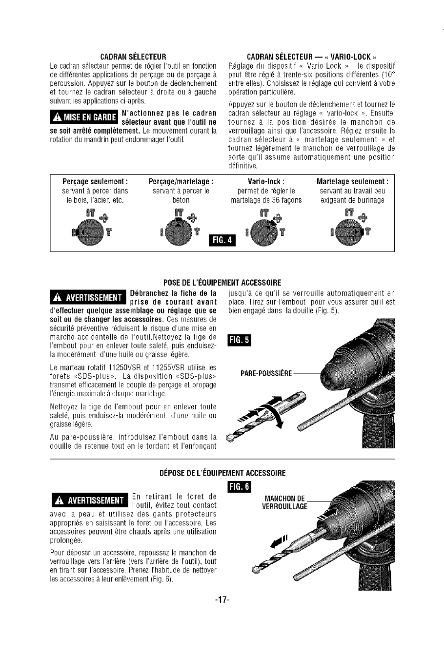
Pert;age seulement : Perr_;age/martelage : Vario-lock : Martelage seulement :
servant _ percer dans servant _ percer le permet de r_gler le servant autravail peu
le bois, I'acier. etc. b_ton martelage de 36 fa_ons exigeant de burinage
I1=[_[!,
POSEDE L'I_QUIPEMENTACCESSOIRE
_D_hranchez la fiche de la
prise de courant avant
d'effectaer quelque assemblage ou r_glage que ce
salt oo de changer les accessoires. Ces mesures de
s_curit_ preventive r_duisent le risque d'une rnise en
marche accidentelle de I'outiI.Nettoyez la tige de
I'embout pour en enlever toute saletd, puis enduisez- /
la moddrdment d'une huile ou graisse I_g_re.
Le marteau rotatif 11250VSR et 11255VSR utilise les
forets <<SDS-plus,,. Ladisposition _<SDS-plus,,
transmet efficacement le couple de per_age et propage
I'dnergie maximale _ chaque martelage.
Nettoyez la tige de I'embout pour en enlever toute
salet_, puis enduisez-la mod_r_ment d'une huile ou
graisse Idg_re.
Au pare-poussi_re, introduisez I'embout dans la
douille de retenue tout en le tordant et I'enfonqant
jusqu'_, ce qu'il se verrouille automatiquement en
place. Tirez sur I'embout pour vous assurer qu'il est
bien engag_ dans la douille (Fig.5).
DISPOSEDE L'I_QUIPEMENTACCESSOIRE
m
_ En retirant le foret de
I'outil, dvitez tout contact
avec la peau et utilisez des gants protecteurs
approprids en saisissant le foret ou I'accessoire. Les
accessoires peuvent _tre chauds apr_s une utilisation
prolong_e.
Pour ddposer un accessoire, repoussez le manchon de
verrouillage vers I'arri_re (vers I'arri_re de I'outil), tout
en tirant sur I'accessoire. PrenezI'habitude de nettoyer
lesaccessoires Aleur enl_vement(Fig.6).
MANCHONDE
VERROUILLAGE
-17-
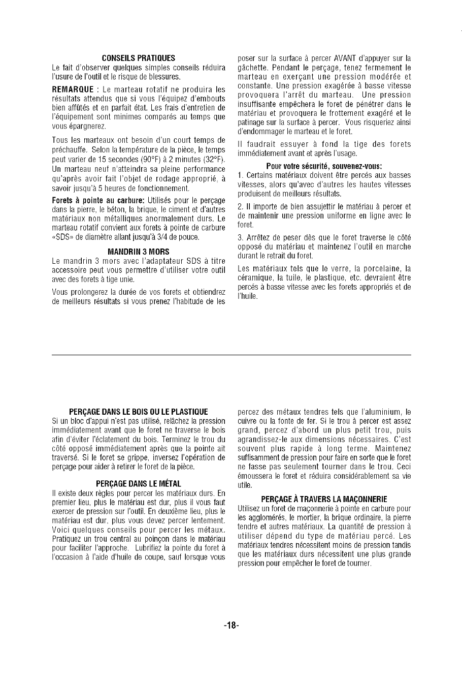
CONSEILSPFIATIQUES
Le fait d'observer quelques simples conseils r_duira
I'usure de I'outil et le risque de blessures.
FIEMAFIQUE: Le marteau rotatif ne produira les
r_sultats attendus que si vous I'dquipez d'embouts
bien affgt_s et en parfait dtat. Les frais d'entretien de
I'_quipement sont minimes compares au temps que
vous epargnerez.
Tous les marteaux ont besoin d'un court temps de
prdchauffe. Selon la temperature de la piece, le temps
peut varier de 15 secondes (90°F) _ 2 minutes (32°F).
Un marteau neuf n'atteindra sa pleine performance
qu'apr_s avoir fait I'objet de rodage approprie,
savoir jusqu'& 5 heures de fonctionnement.
Forets _ pointe au carbure: Utilises pour le per_age
dans la pierre, le beton la brique le ciment et d'autres
mat_riaux non metalliques anormalement durs. Le
marteau rotatif convient aux forets & pointe de carbure
<<SDS>>de diam_treallant jusqu'& 3/4 de pouce.
MAHDI:lIB 3MOBS
Le mandrin 3 mors avec I'adaptateur SDS & titre
accessoire peut vous permettre d'utiliser votre outil
avec desforets &tige unie.
Vous prolongerez la duree de vos forets et obtiendrez
de meilleurs r_sultats si vous prenez I'habitude de les
poser sur la surface _ percer AVANTd'appuyer sur la
g_chette. Pendant le per£age, tenez fermement le
marteau en exer£ant une pression mod_ree et
constante. Une pression exag_ree _ basse vitesse
provoquera I'arret du marteau. Une pression
insuffisante empechera le foret de p_n_trer dans le
mat_riau et provoquera le frottement exag_re et le
patinage sur la surface & percer. Vous risqueriez ainsi
d'endommager le marteau et le foret.
II faudrait essuyer A fond la tige des forets
imm_diatement avant et apr_s I'usage.
Pour votres_curit_, souvenez-vous:
1. Certains materiaux doivent _tre perc_s aux basses
vitesses, alors qu'avec d'autres les hautes vitesses
produisent de meilleurs resultats.
2. II importe de bien assujettir le materiau _ percer et
de maintenir une preesion uniforme en ligne avec le
foret.
3. Arretez de peser d_s que le foret traverse le c6td
opposd du mat_riau et maintenez I'outil en marche
durant le retrait du foret.
Les mat_riaux tels que le verre, la porcelaine, la
ceramique, la tuile, le plastique, etc. devraient _tre
percds _ basse vitesse avec les forets appropri_s et de
I'huile.
PERI;AGEDANSLE BOISOULE PLASTIQUE
Si un bloc d'appui n'est pas utilis_, relgchezla pression
immediatement avant que le foret ne traverse le bois
afin d'dviter I'eclatement du bois. Terminez le trou du
c6td oppose immediatement apr_s que la pointe ait
travers& Si le foret se grippe, inversez I'opdration de
per;age pour aider _ retirer le foret de la piece.
PERI_AGEDANSLEIVlI_TAL
II existe deux regles pour percer les materiaux durs. En
premier lieu, plus le matdriau est dur, plus il vous faut
exercerde pression sur I'outiL En deuxiemelieu, plus le
materiau est dur, plus vous devez percer lentement.
Voici quelques conseils pour percer les metaux.
Pratiquez un trou central au poin;on dans le mat_riau
pour faciliter I'approche. Lubrifiez la pointe du foret
I'occasion _ I'aide d'huile de coupe, saul Iorsque vous
percez des metaux tendres tels que I'aluminium, le
cuivre ou la fonte de fer. Si le trou _ percer est assez
grand, percez d'abord un plus petit trou, puis
agrandiseez-le aux dimensions necessaires. C'est
souvent plus rapide _ long terme. Maintenez
suffisamment de pression pour faire en sorte que le foret
ne fasse pas seulement tourner dans le trou. Ceci
emoussera le foret et rdduira consid_rablement sa vie
utile.
PER(_AGE._TRAVERSLAMA(_ONNERIE
Utilisez un foret de ma_onnerie_ pointeen carbure pour
les agglom_res, le mortier, la brique ordinaire, la pierre
tendre et autres materiaux. La quantite de pression
utiliser ddpend du type de materiau perc_. Les
mat_riaux tendres necessitent moins de pression tandis
que les materiaux durs necessitent une plus grande
pression pour emp_cher le foret de tourner.
-18-
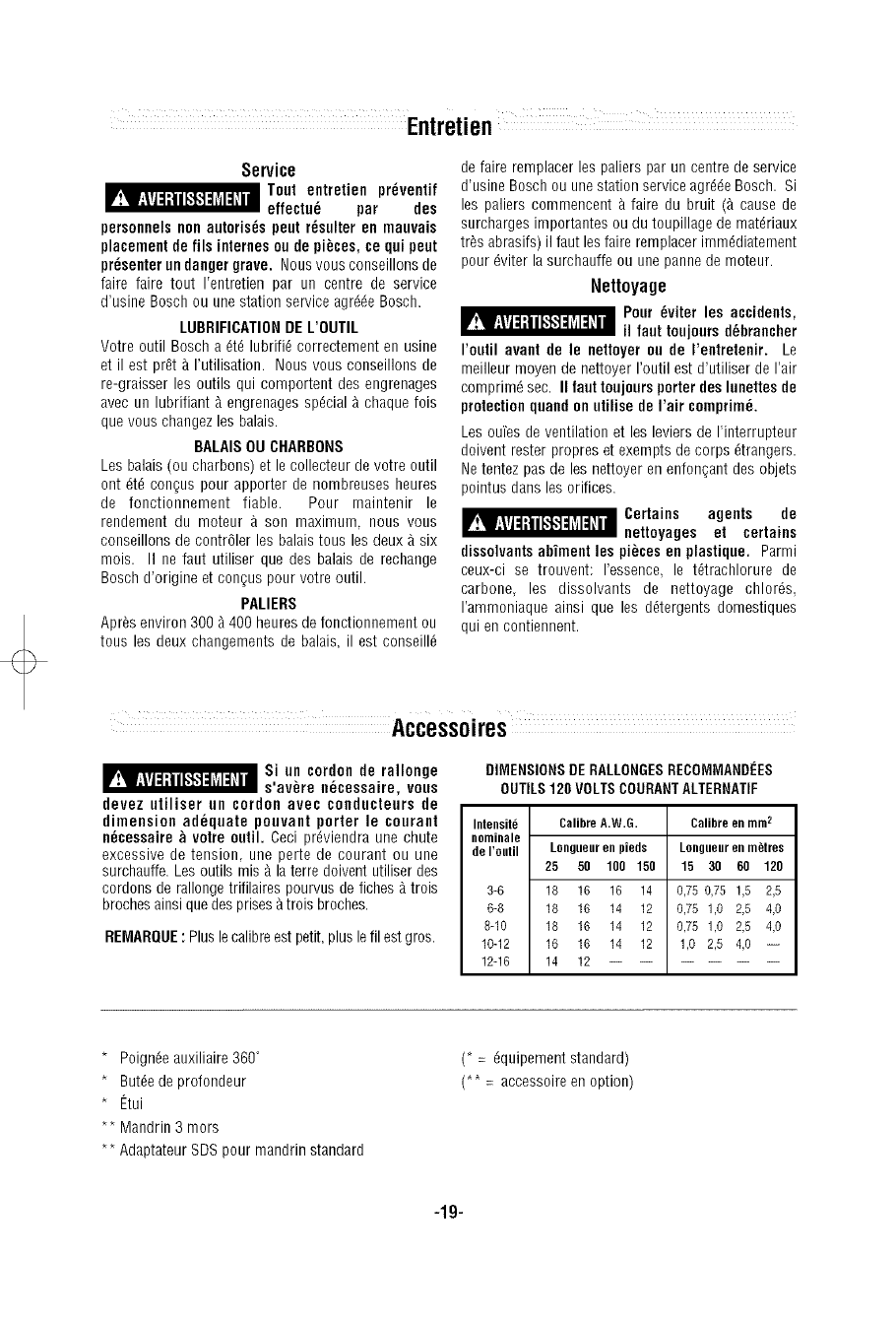
Service
Toot entretien pr_ventif
effectu_ par des
personnels non autoris_s pent r_sulter en mauvais
placement de ills internes ou de pi_ces, ce qoi pent
presenter nn danger grave. Nous vous conseillons de
fake faire tout I'entretien par un centre de service
d'usine Bosch ou une station service agr_e Bosch.
LUBRIFICATIONDE L'OUTIL
Votre outil Bosch a _t_ lubrifi_ correctement en usine
et il est pr_t _ I'utilisation. Nous vous conseillons de
re-graisser les outils qui comportent des engrenages
avec un lubrifiant _ engrenages special _ chaque fois
que vous changez los balais.
BALAISOU CHARBONS
Les balais (ou charbons) et le collecteur de votreoutil
ont _t_ con_us pour apporter de nombreuses heures
de fonctionnement fiable. Pour maintenir le
rendement du moteur & son maximum, nous vous
conseillons de contr61er les balais tousles deux _ six
mois. II ne faut utiliser que des balais de rechange
Bosch d'origine et census pour votre outih
PALIERS
Apr_s environ 300 _ 400 heures de fonctionnement ou
tousles deux changements de balais, il est conseilld
de faire remplacer los paliers par un centre de service
d'usine Bosch ou une station service agr_e Bosch. Si
les paliers commencent & faire du bruit (_ cause de
surcharges importantes ou du toupillage de mat_riaux
tr_s abrasifs) il faut les fake remplacer imm_diatement
pour _viter la surchauffe ou une panne de moteur.
Nettoyage
Pour _viter les accidents,
il faut toujoors d_brancher
I'outil avant de le nettoyer ou de I'entretenir. Le
rneilleur moyen de nettoyer I'outil est d'utiliser de I'air
comprim_ sec. II faut toojours porter des lunettes de
protection qoand on utilise de I'air comprim_,
Les oufes de ventilation et les leviers de I'interrupteur
doivent rester propres et exempts de corps _trangers,
Ne tentez pas de les nettoyer en enfonqant des objets
pointus dans les orifices.
_Certains agents de
nettoyages et certains
dissolvantsabfment Ins pi_ces en plastique. Parmi
ceux-ci se trouvent: I'essence, le t_trachlorure de
carbone, les dissolvants de nettoyage chlords,
I'ammoniaque ainsi que les ddtergents domestiques
qui en contiennent.
_Si on cordonde rallonge
s'av_re n_cessaire, vous
devez ntiliser un cordonavec conducteursde
dimensionadequatepoovantporter le courant
n_cessaire_votreoutil.Ceciprdviendraune chute
excessivede tension unepertedecourantouune
surchauffe.Lesoutils mis_ laterredoiventutiliserdes
cordonsderallongetrifilairespourvusdefiches_trois
brochesainsiquedesprises&troisbroches.
REMARQUE: Plus lecalibre est petit, plus le fll estgros.
DIMENSIONSDERALLONGESRECOMMANDEES
OUTILS120 VOLTSCOURANTALTERNATIF
Intensite CalibreA.W.G.
neminale
de I'eutil Longueur en pieds
25 50 100 150
3-6 18 16 16 14
6-8 18 16 14 12
8-10 18 16 14 12
10-12 16 16 14 12
12-16 14 12
Calibre en mm2
Lollgtlellr ell metres
15 30 60 120
0,75 0,75 1,5 2,5
0,75 1,0 2,5 4,0
0,75 1,0 2,5 4,0
1,0 2,5 4,0 --
* Poign_e auxiliaire 360°
* Butdede profondeur
* Etui
** Mandrin 3 mors
** Adaptateur SDS pour mandrin standard
(* =_quipement standard)
(** = accessoire en option)
-19-
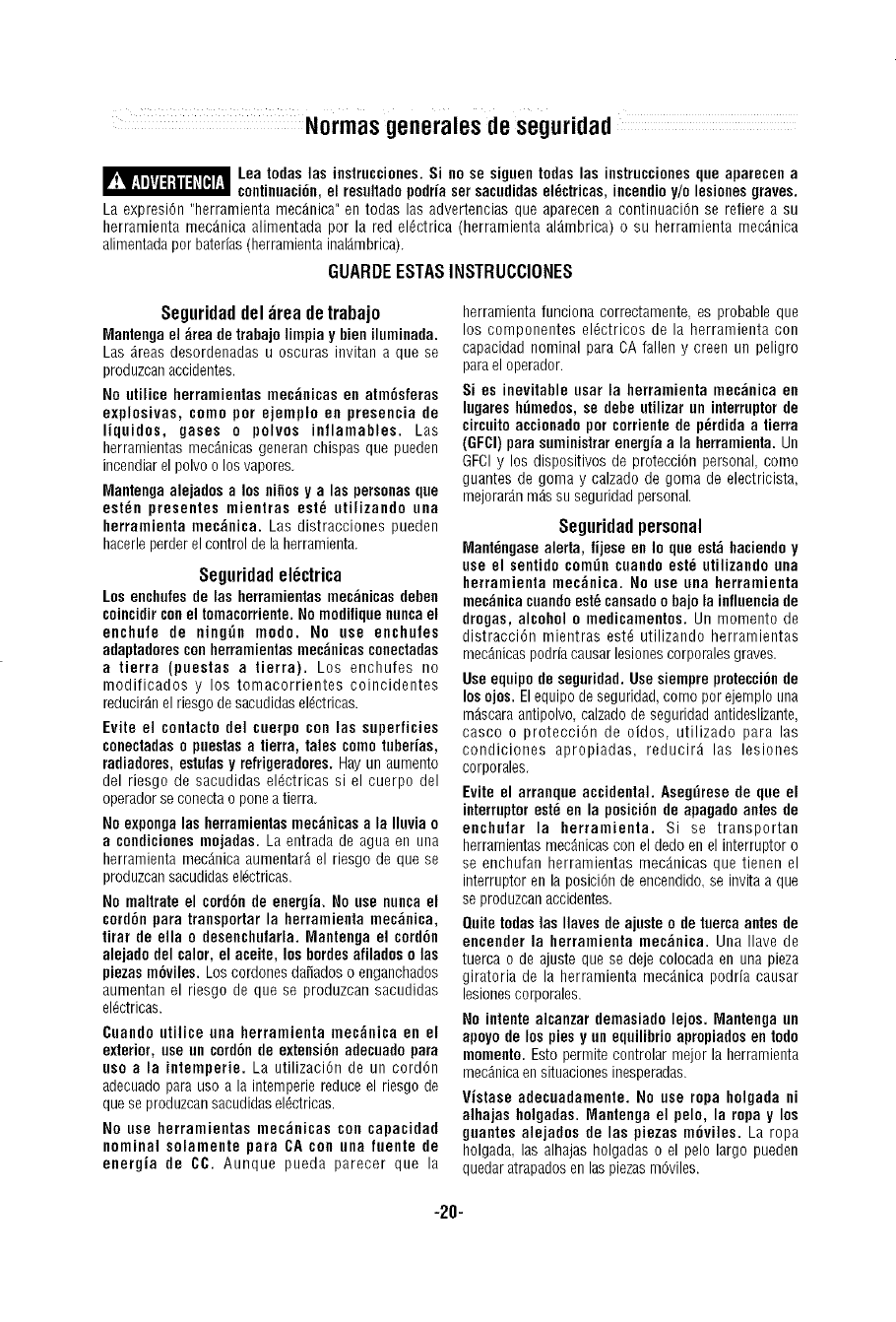
Normas generalesdeseguridad
Leatodaslas instrucciones.Si nose siguentodaslas instruccionesque aparecena
continuaci6n,el resultadopodriasersacudidaselHctricas,incendioy/e lesienesgraves.
Laexpresi6n"herramientamec_nica"en todas las advertenciasque aparecena continuaci6nse refierea su
herramientamec_nicaalimentadapor la red eldctrica (herramientaal_mbrica)o su herramientamec9nica
alimentadaporbaterias(herramientainal9mbrica).
GUARDEESTASINSTRUCCIONES
Seguridaddel;ireadetrabajo
Mantenga el ;_reade trahajolimpia y bieniluminada.
Las _reas desordenadas u oscuras invitan a que se
produzcanaccidentes.
No utilice herramientas mec;_nicas en atm6sferas
explosivas, como per ejemplo en presencia de
liquidos, gases o polvos inflamahles. Las
herrarnientas mec_nicas generan chispas que pueden
incendiar el polvo o los vapores.
Mantenga alejades a los cities y a las personasque
estHn presentes mientras est_ utilizando una
herramienta mec_nica. Las distracciones pueden
hacerleperderel control de la herramienta.
Seguridadel_ctrica
Los enchufes de las herramientas mec_nicas dehen
coincidirconel tomacorriente.No modifique nuncael
enchufe de ning_n modo. No use enchufes
adaptadores con herramientasmec_nicas conectadas
atierra (puestas atierra). Los enchufes no
modificados y los tomacorrientes coincidentes
reducir_nel riesgo de sacudidas el_ctricas.
Evite el contacto del cuerpo con las superficies
conectadaso puestasa tierra, tales come tuber[as,
radiadores, estufasy refrigeradores.Hay un aumento
del riesgo de sacudidas el_ctricas si el cuerpo del
operador se conecta o pone a tierra
No expongalas herramientasmec_nicas a la Iluvia o
acondiciones mojadas. La entrada de agua en una
herramienta mec_nicaaumentar_ el riesgo de que se
produzcansacudidas eldctricas.
No maltrate el cord6nde energia. No use nunca el
cord6n para transportar la herramienta mec;_eica,
tirar de ella o desenchufarla. Mantenga el cord6n
alejado del caler, el aceite, loshordesafilados o las
piezas m(_viles. Los cordones da_ados o enganchados
aumentan el riesgo de que se produzcan sacudidas
el_ctricas.
Cuando ntilice una herramienta mec;_nica en el
exterior, use un cord6n de extensi6n adecuado para
uso ala intemperie. La utilizaci6n de un cord6n
adecuado para uso a la intemperiereduce el riesgo de
que se produzcansacudidasel_ctricas.
No use herramientas mec_nicas con capacidad
nominal solamente para CA con una fuente de
energia de CC. Aunque pueda parecer que la
herramienta funciona correctamente, es probable que
los componentes el_ctricos de la herramienta con
capacidad nominal para CA fallen y creen un peligro
parael operador.
Si es inevitable usar la herramienta mec_nica en
lugares h[imedos,se debe utilizar un interruptor de
circuito accionado por corriente de pHrdidaatierra
(GFCI)para suministrarenergiaala herramienta. Un
GFCIy los dispositivos de protecci6n personal como
guantes de goma y calzado de goma de electricista,
mejorar9n mdssu seguridad personal.
Seguridadpersonal
MantHngasealerta, fijese en Io que est_ haciendo y
use el sentido comtin cuaedo estH utilizando una
herramienta mec;_nica. No use una herramienta
mec_nicacuandoest_ cansadoo bajo la influenciade
drogas, alcohol omedicamentos. Un momento de
distracci6n mientras estd utilizando herramientas
mec_nicaspodria causarlesiones corporales graves
Use equipo de seguridad. Use siempre protecci6nde
los ojos. Elequipo de seguridad, como por ejernplo una
m_scara antipolvo calzado de seguridad antideslizante,
casco o protecci6n de oidos utilizado para las
condiciones apropiadas, reducir_ las lesiones
corporales.
Evite el arranque accidental. Aseg[irese de que el
interruptorestH en la posici6n de apagadoantes de
enchufar la herramienta. Si se transportan
herrarnientasmec_nicascon el dedo en el interruptor o
se enchufan herramientas mecgnicas que tienen el
interruptor en la posici6n de encendido,se invita a que
se produzcanaccidentes.
Quite todas las Ilaves de ajuste o detuerca antes de
encender la herramienta mec_nica. Una Ilave de
tuerca o de ajuste que se deje colocada en una pieza
giratoria de la herramienta mec_nica podria causar
lesionescorporales.
No intente alcanzar demasiado lejos. Mantenga un
apoyode los piesy un equilibrio apropiadosen todo
memento. Esto permite controlar mejor la herrarnienta
mec_nicaen situacionesinesperadas.
Vistase adecuadamente. No use ropa holgada ni
alhajas holgadas. Mantenga el pelo, la ropa y los
guantes alejados de las piezas m6viles. La ropa
holgada las alhajas holgadas o el pelo largo pueden
quedar atrapadosen laspiezasm6viles.
-20-
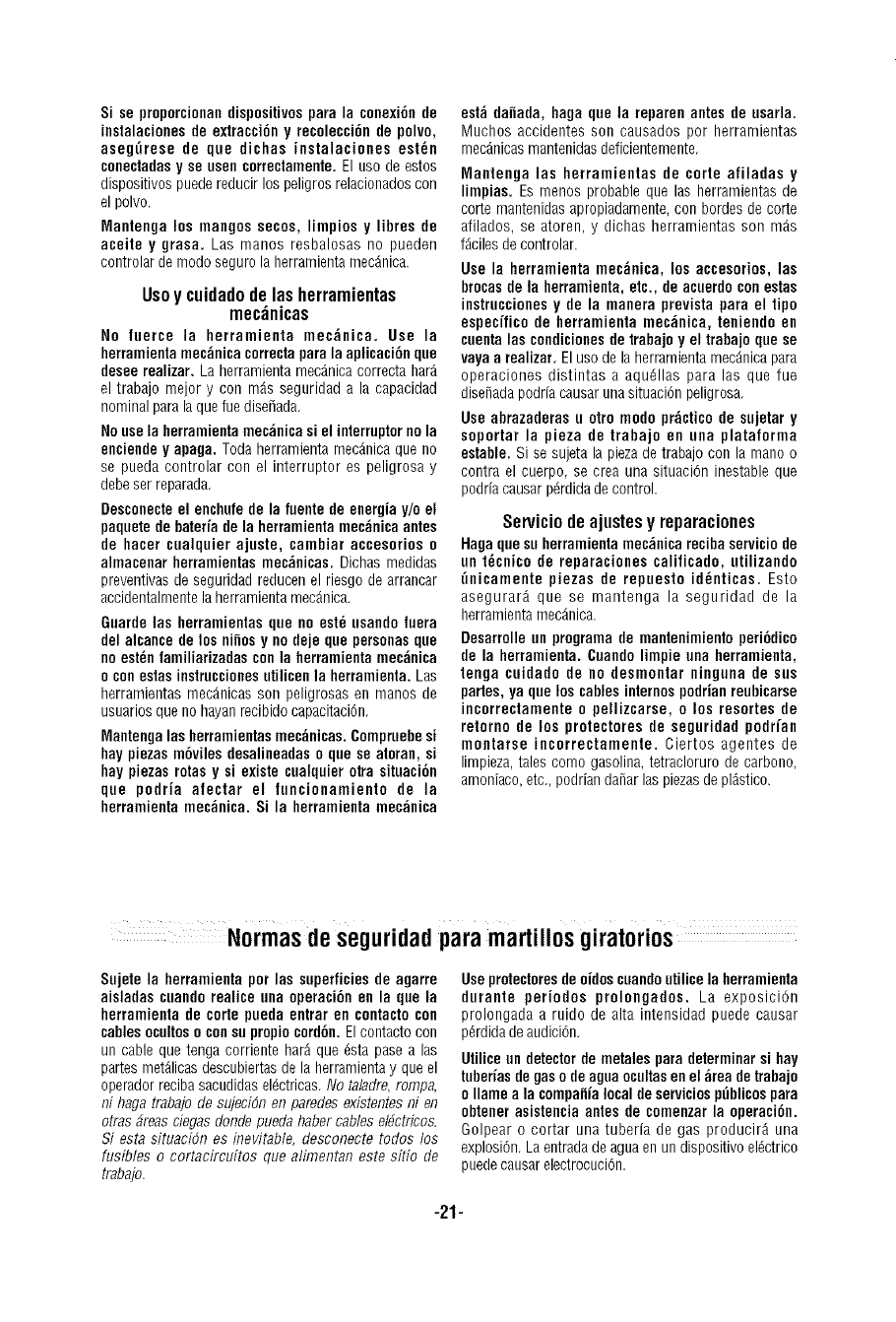
Si seproporcionandispositivospara la conexi6nde
instalacionesde extracci6ny recoleccidnde polvo,
aseg_rese de que dichas instalaciones est_n
conectadasy se usen correctamente.Elusodeestos
dispositivospuedereducirlospeligrosrelacionadoscon
elpolvo.
Mantengalos mangos secos,limpiosy libres de
aceite y grasa. Las manos resbalosasno pueden
controlardemodosegurolaherramientamecdnica.
Usoy cuidadodelasherramientas
mec;inicas
No luerce la herramienta mec_nica. Use la
herramientamec_nicacorrectapara la aplicaci6n que
desee realizar. La herramienta mecdnica correcta hard
el trabajo mejor y con mds seguridad a la capacidad
nominal para laque fue dise_ada,
Nouse la herramientamec_nica si el interroptorno la
enciendey apaga. Toda herramienta rnecdnica que no
se pueda controlar con el interruptor es peligrosa y
debeser reparada,
Desconecteel enchufede la fuente de energia y/o el
paquete debaterfa de la herramienta mec;_nicaantes
de hacer cualquier ajuste, cambiar accesorios o
almacenar herramientas mec_nicas. Dichas medidas
preventivas de seguridad reducen el riesgo de arrancar
accidentalmentela herramienta mecdnica,
Guarde las herramientas que no est_ usandoluera
del alcance de los ninosy no deje que personas que
no est_nfamiliarizadas con la herramientamec_nica
oconestas instruccionesutilicenla herramienta. Las
herramientas mecdnicas son peligrosas en manos de
usuarios que no hayan recibido capacitaci6n,
Mantengalas herramientasmec;inicas. Compruebe si
hay piezas m6viles desalineadaso que se atoran, si
hay piezas rotas y si existe cualquier otra situaci6n
que podria alectar el luncionamiento de la
herramienta mec;_nica.Si la herramienta mec_nica
est_ danada, haga que la reparen antes de usarla.
Muchos accidentes son causados por herrarnientas
mecdnicasmantenidasdeficientemente,
IVlantenga las herramientas de corte afiladas y
limpias. Es menos probable que las herramientas de
corte mantenidas apropiadamente con bordes de corte
afilados, se atoren, y dichas herramientas son rods
fdciles de controlar.
Use la herramienta mec_nica, los accesorios, las
brocasde la herramienta, etc., de acuerdo con estas
instrucciones y de la manera prevista para el tipo
especffico de herramienta mec_nica, teniendo en
cuenta lascondicionesde trabajo y el trabajo que se
vaya arealizar, El uso de la herramienta mecdnica para
operaciones distintas a aqudllas para las que fue
diseSadapodria causaruna situaci6n peligrosa,
Use abrazaderas u otto modo pr;_cticode sujetar y
soportar la pieza de trabajo en una plataforma
estable. Si se sujeta la piezade trabajo con la rnano o
contra el cuerpo se crea una situaci6n inestable que
podria causar pdrdida de control
Serviciodeajustesy reparaciones
Hagaque suherramienta mec_nica recihaserviciode
un t_cnico de reparaciones calificado, utilizando
_nicamente piezas de repuesto id_nticas. Esto
asegurard que se rnantenga la seguridad de la
herramienta mecdnica.
Desarrolle un programa de mantenimiento peri6dico
de la herramienta. Cuandolimpie ona herramienta,
tenga cuidado de no desmontar ningona de sos
patios, ya que los cables infernospodrianreobicarse
incorrectamente opellizcarse, o los resortes de
retorno de los protectores de seguridad podrfan
montarse incorrectamente, Ciertos agentes de
limpieza,tales come gasolina, tetracloruro de carbono,
amoniaco,etc, podrian danar las piezasde pldstico.
Normasdeseguridadpara martillosgiratorios
Sujete la herramienta por las superficiesde agarre
aisladas cuandorealice una operaci6n en la que la
herramienta de corte pueda entrar en contacto con
cables ocultoso conso propiocord6n.El contacto con
un cable que tonga corriente hard que 6sta pase alas
partes metdlicasdescubiertas de la herramientay que el
operadorreciba sacudidasel6ctricas,No taladre,rompa,
ni haga trabajo de sujeci(_nenparedes existentes ni en
otras 6reas ciegasdonde pueda habercables et#ctricos.
Siesta situaci6n es inevitable, desconecte todos los
fusibles o cortacircuitos que alimentan este sitio de
trabajo.
Useprotectoresdeoidoscuandoutilicela herramienta
durante periodos prolongados. La exposici6n
prolongadaa ruido de altaintensidadpuedecausar
p6rdidadeaudici6n,
Utiliceundetectordemetalesparadeterminarsi hay
tuberiasdegasodeaguaocultasenel ;_readetrabajo
oIlamea lacompanialocaldeserviciosp_blicospara
obtenerasistenciaantesde comenzarla operaci6n.
Golpearo cortar unatuberia de gas producird una
explosi6n,Laentradade aguaen undispositivoeldctrico
puedecausarelectrocuci6n,
-21-
Utilice siempre el mango auxiliar para tener on
control m_ximo sobre la reacci6n de par motor o
retroceso. Nunca intente manejar esta herramienta
con nna mano. El embrague deslizante se acopla si
usted controla firmemente la herramienta durante una
reacci6nde par motor o retroceso.
Use siempre gafas de seguridado protecci6n de los
ojos cuando utilice esta herramienta. Use ona
m_scara antipolvooan respiradorpara aplicaciones
que generan polvo. Los galas de seguridad o la
protecci6n de los ojos ayudar_n a desviar los
fragmentos del material que puedan salir despedidos
hacia la cara y los ojos. El polvo generado o los gases
liberados por los materialesque est_ cortando (por ej.,
tuberias con aislamiento de asbesto, rad6n) pueden
causardificultadesrespiratorias.
Use guantes con almohadillado groeso ylimite el
tiempode exposici6ntomandofrecoentes periodos de
descanso. La vibraci6n causada por la acci6n de
percusi6n y taladrado puede ser perjudicial para las
manosy los brazos.
Posicione el ¢ord6n de modo que est_ alejado de la
broca que gira. No enrolle el ¢ord6n alrededor del
brazo ode la mu_eca. Si pierde el control y tieee el
cord6n enrollado en el brazo o en la mu_eca, el cord6n
puedeatraparley causarlelesiones.
Sitt_ese de modo qoe evite ser atrapado entre la
herramienta o el mango lateral y las paredes o los
posies. Si la broca se atasca o se engancha en la
piezadetrabajo el par motor de reacci6n de la
herramienta podria aplastarle la mane o la pierna.
No golpee la broca con on martillo de mano ni con
una herramienta de martilleo cuando intente soltar
una brocaatascadao enganchada. Se podr[an soltar
fragrnentos de metal de la broca y golpearle a usted o
golpeara laspersonasque se encuentrenpresentes.
Nunca deje la berramientaen ningtin lugar basraqae
la broca o el accesorio se haya detenido por
completo.
Noutilicebrocas ni accesoriosdesafiladosodanados.
Las brocas o accesorios desafiladoso da_ados pueden
atascarse frecuentemente en la pieza de trabajo,
causandouna reacci6nde parmotor.
AI sacar la broca de la herramienta,evite el contacto
con la piel y use guantes de protecci6n adecuadosal
agarrar la broca oel accesorio. Losaccesorios pueden
estar calientesdespu_sde un use prolongado.
Notenga en marcha la berramientamientras la Ileva
asu lado. La broca taladradora que gira puede
engancharseen la ropay se puedenproducir lesiones.
_ Cierto polvo generado pot el
lijado, aserrado, amolado y
taladrado mec_nicos, y por otras actividades de
construcci6n, contiene agentesquimicos qae se sabe
qne causan ¢_ncer, defectos de nacimiento uotros
da_os sobre la reproducci6n.Alganos ejemplos de
estosagentesquimicos son:
• Plomo de pinturas a base de plomo,
• Silice cristalina de ladrillos y cemento y otros
productos de mamposteria,y
• Ars_nicoy cromo de maderatratada quimicamente.
Su riesgo por causa de estas exposiciones varia,
dependiendo de con cu_nta frecuencia realice este tipo
de trabajo. Para reducir su exposici6n a estos agentes
quimicos: trabajeen un _rea bien ventiladay trabajecon
equipo de seguridad aprobado, como por ejemplo
mdscarasantipolvo que estdn disenadas especialmente
para impedir mediante filtraci6n el paso de particulas
microsc6picas.
-22-

IMPORTANTE: Es posible que algunos de los sfmbolos siguientes se usen en su herramienta. Por favor,
est0dielos y aprenda su significado. La interpretaci6n adecuada de estos simbolos le permitir_ utilizar la
herramienta mejor y con m9s seguridad.
Simbolo Nombre Designaci6n/explicaci6n
V Volt Tensi6n (potencial)
A Ampere Corriente
Hz Hertz Frecuencia (ciclos por segundo)
W Watt Potencia
kg Kilogramo Peso
rain Minuto Tiempo
s Segundo Tiempo
O Didmetro Tama_o de las brocas taladradoras,
muelas, etc.
no Velocidad sin carga Velocidad rotacional sin carga
.,drain Revolucioneso alternaci6n por minuto Revoluciones, golpes, velocidad de
superficie, 6rbitas, etc., por minuto
0 Posici6n "off" (apagado) Velocidad cero, par motor cero._
1,2, 3.... Graduaciones del selector Graduaciones de velocidad, par motor o
I, II, III, posici6n, Un n0mero rods alto significa
mayor velocidad
Selector infinitamente variable con La velocidad aumenta desde la
apagado graduaci6n de 0
--_' Flecha Acci6n en la direcci6n de la flecha
Corriente alterna Tipo o una caracterfstica de corriente
= Corriente continua Tipo o una caracterfstica de corriente
rk, Corriente alterna ocontinua Tipo o una caracterfstica de corriente
[] Construcci6n de clase II Designa las herramientas de construcci6n
con aislamiento doble.
_) Terminal de toma de tierra Terminal de conexi6n a tierra
/_ Simbolo de advertencia Alerta al usuario sobre mensajes de
advertencia
Sello RBRCTM de Ni-Cd Designa el programa de reciclaje de baterias
de Ni-Cd
Estesimbolo indica que esta @
herramienta est_ catalogada
por Underwriters C
Laboratories,
. ste sfmbolo indica que esta
herramienta est4 catalogada
por la CanadianStandards
Association.
Estesfmbolo indica que
Underwriters Laboratories ha
catalogadoesta herramienta
indicando que cumple las
normas canadienses.
Estesimbolo indica que esta
herramienta est_ catalogada por
Underwriters Laboratories y que
US Underwriters Laboratories la ha
catalogado seg0n las normas
canadienses,
Estesimbolo
indica que esta
herramienta
cumple con la
norma mexicana
oficial (NOM),
-23-
Descripci6nfuncionaly especificaciones
_esconecteel enchufede la fuente de energia antes de realizar cualquier ensamblajeo
ajuste, o cambiar accesorios. Estas medidas de seguridad preventivas reducenel riesgo
de arrancar la herramienta accidentalmente.
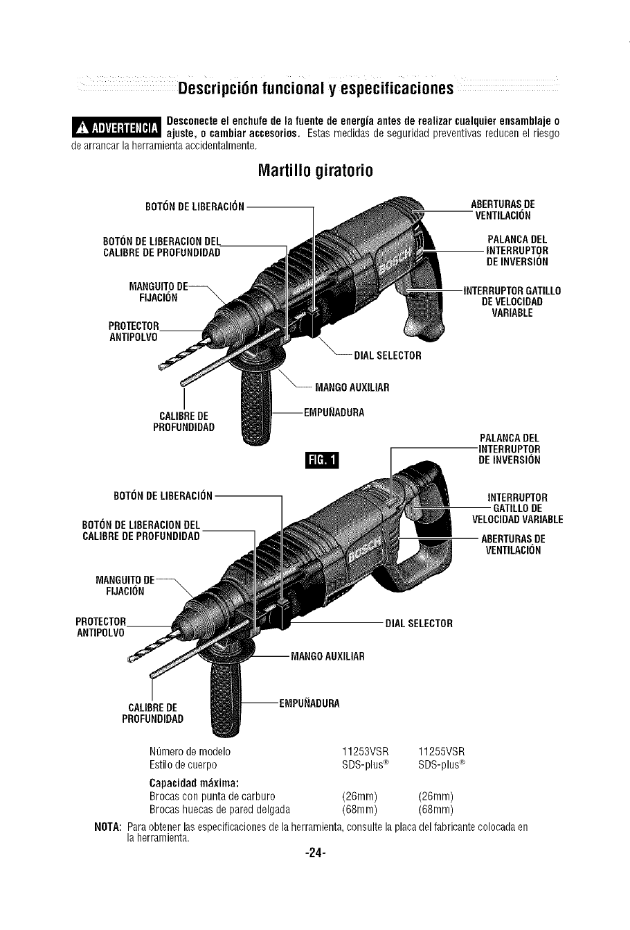
IVlartillogiratorio
BOTONDELIBERACB)N
80TOI']DELIBERACIONDEL
CALIBREDEPROFUNDIDAD
ABERTURASDE
VENTILACION
PALANCADEL
INTERRUPTOR
DEINVERSION
MANGUITODE_ INTERRUPTORGATILLO
FIJACION "_ DEVELOCIDAO
VARIABLE
PROTECTOR
ANTIPOLVO
I
CALIBREDE
PROFUHDIDAD
DIALSELECTOR
_MANGOAUXILIAR
PALANCADEL
INTERRUPTOR
r_ DEINVERSION
BOTONDE LIBERACION
BOTONDELIBERACIONDEL
CALIBREDEPROFUNDIDAD
INTERRUPTOR
GATILLODE
VELOCIDADVARIABLE
ABERTURASDE
VENTILACION
MANGUITODE_
FIJACION "_
PROTECTOR
ANTIPOLVO DIALSELECTOR
CALIBREDE
PROFUNDIDAD
Nt_merode modelo 11253VSR 11255VSR
Estilode cuerpo SDS-plus® SDS-plus®
Capacidadm_xima:
Brocas con punta de carburo (26ram) (26ram)
Brocas huecas de pared delgada (68ram) (68ram)
NOTA: Paraobtener las especificacionesdela herramienta,consulte la placadel fabricante colocadaen
la herramienta.
-24-
INTERRUPTORGATILLODE VELOCIDADVARIABLE
CONTROLADA
La herramienta est_ equipada con un interruptor gatillo
de velocidad variable. La velocidad de la herramientase
puedecontrolar desde las RPM minimas hastalas RPM
mdximas indicadasen la placa del fabricante por medio
de la presi6n que usted ejerce sobre el gatillo. Ejerza
rods presi6n paraaumentar la velocidad y disminuya la
presi6n para reducir la velocidad. Estepreciso control
de velocidad le permite a usted taladrar sin realizar
punzonaduraspara marcar. Tambidn le permite utilizar
la herramienta como destornillador mecgnico. Hay
brocasdisponibles para apretar tornillos y tambi_n para
pernosy tuercas.
PALANCADELINTERRUPTORDE INVERSI(_N
Esta herramienta est_ equipada con el sistema de
inversi6n de escobillas giratorias. Esto tiene como
resultado una vida m_s larga a la vez que maximiza la
potencia tanto en el sentido de avance como en el
inverso. El interruptor de inversi6n se puede accionar
desde el lado derecho o desde el lado izquierdo de la
herramienta.
PARALA ROTACIONDEAVANCE:desplaceelinterruptor
hastala flecha marcadaavance(FWD)(Fig. 1).
PARALA ROTACIONEN SENTIDOINVERSO:desplaceel
interruptor hasta la flecha marcada inversi6n (REV).
NOTA:la herramientanofuncionard con el interruptor en
laposici6n central.
EMBRAGUEDESLIZANTE
La herramienta tiene un embrague interno preajustado.
Elembragueestd ajustadode tal modo que setransmita
suficiente fuerza a la broca en la mayoria de la
situaciones de taladrado, pero patinar_ cuando la broca
se atasque en el agujero o la herramienta se
sobrecargue. Tenga presente quedebidoalajuste
requerido para el embrague, se podr_ producir una
reacci6n de par motor un instante antes de que el
embrague patine. Estareacci6nde par motor torcerd el
cuerpo del martillo giratorio en sentido contrario al del
giro de la broca, es decir, en sentido contrario al de las
agujas del reloj. Cuando el embrague patine, Io mgs
probablees quelabrocadejedegirar. Cuando se
elimina la fuerza que el atasco ejercesobre la broca, el
embrague se reajusta automdticamente. Si se produce
atasco de la hoja y el embrague comienza a patinar,
apague la herramienta inmediatamente y corrija la
situaci6n que haceque la hojase atasque.
MANGOAUXILIAR
La herramienta se debe sujetar con el mango auxiliar,
el cual se puede girar 360° . Para reposicionar y/o
hacer girar el mango, afloje la empu_adura, mueva el
mango hasta la posici6n deseadaa Io largo del cuerpo
cilindrico y vuelva a apretar firmemente la
empuffadura.
EMPUNADURA
CALIBREDE PROFUNDIDAD
La profundidad de perforaci6n se puede prefijar y/o
repetir utilizandoel calibre de profundidad.
Ajuste de la profundidad: Despuds de instalar el
mango auxiliar, aseg_rese de que el accesorio se haya
introducido completamente en el portaherramienta
antes de ajustar el calibre de profundidad (Fig. 3).
Para ajustar la profundidad, oprima el bot6n de
liberaci6n del calibre de profundidad, deslice dicho
calibre hasta la profundidad deseada y deje de ejercer
presi6n sobre el bot6n para fijar el calibre de
profundidad en su sitio.
m
CALIBREBE
PROFUNBIDAD
BOTONDE
LIBERACION
BELCALIBRE
BE
PROFUNDIDAD
-25-
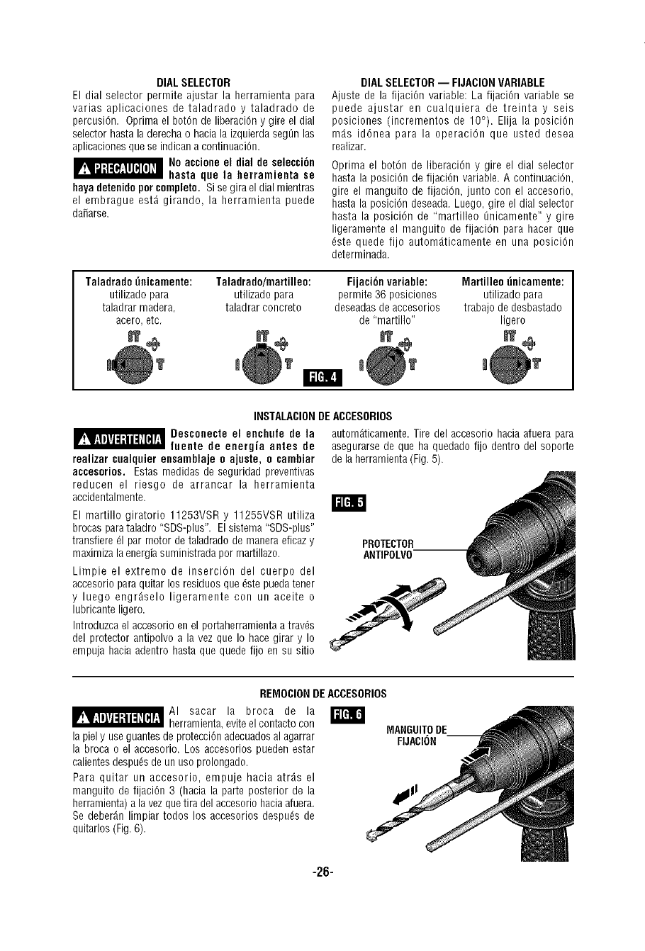
DIAL SELECTOR
El dial selector permite ajustar la herramienta para
varias aplicaciones de taladrado y taladrado de
percusi6n. Oprima el bot6n de liberaci6n y gire el dial
selector hasta laderecha o hacia la izquierdaseg_n las
aplicaciones que se indican a continuaci6n.
No accione el dial de selecci6n
hasta que la herramienta se
hayadetenidoper complete. Si se gira el dial mientras
el embrague est_ girando, la herramienta puede
da_arse.
DIALSELECTOR-- FIJACIONVARIABLE
Ajuste de la fijaci6n variable: La fijaci6n variable se
puede ajustar en cualquiera de treinta y seis
posiciones (incrementos de 10°). Elija la posici6n
rods id6nea para la operaci6n que usted desea
realizar.
Oprima el bot6n de liberaci6n y gire el dial selector
hasta la posici6n de fijaci6n variable. A continuaci6n,
gire el manguito de fijaci6n, junto con el accesorio,
hasta la posici6n deseada. Luego, gire el dial selector
hasta la posici6n de "martilleo _nicamente" y gire
ligeramente el manguito de fijaci6n para hacer que
dste quede fijo automdticamente en una posici6n
determinada.
Taladrado _eicamente: Taladrado/martilleo: Fijaci6n variable: Martilleo [inicamente:
utilizado para utilizado para perrnite 36 posiciones utilizado para
taladrar madera, taladrar concrete deseadasde accesorios trabajo de desbastado
acero, etc. de "martillo" ligero
J? a? I? M?
T l ! _T
I1=[='_,
INSTALACIONDE ACCESORIOS
_Desconecte el enchufe de la autom_ticamente. Tire del accesorie hacia atuera para
faente de energia antes de
realizar cualquier eesamblaje oajuste, ocambiar
accesorios. Estas rnedidas de seguridad preventivas
reducen el riesgo de arrancar la herramienta
accidentalmente.
El martilio giratorio 11253VSR y 11255VSR utiliza
brocas para taladro "SDS-plus". Elsistema "SDS-plus"
transfiere _1par motor de taladrado de manera eficazy
maximiza laenergia suministrada per martillazo.
Limpie el extreme de inserci6n del cuerpo del
accesorio paraquitar los residues que dste puedatener
y luego engr_selo ligeramente con un aceite o
lubricante ligero.
Introduzca el accesorio en el portaherramienta a travds
del protector antipolvo a la vez que Io hace girar y Io
empuja hacia adentro hasta que quede fijo en su sitio
asegurarse de que ha quedado fijo dentro del soporte
de la herramienta(Fig. 5).
PROTECTOR
ANTIPOLVO
REMOCIONDEACCESORIOS
AI sacar la broca de la W
herramienta,evite el contacto con
la piel y use guantes de protecci6n adecuadosal agarrar
la broca o el accesorio. Los accesorios pueden estar
calientesdespu_sde un uso prolongado.
Para quitar un accesorio, empuje hacia atr_s el
manguito de fijaci6n 3 (hacia la parte posterior de la
herramienta) a la vez que tira del accesorio haciaafuera.
Se deber_n limpiar todos los accesorios despu_s de
quitarlos (Fig.6).
MANGUITODE
FIJACI(_N --
-26-
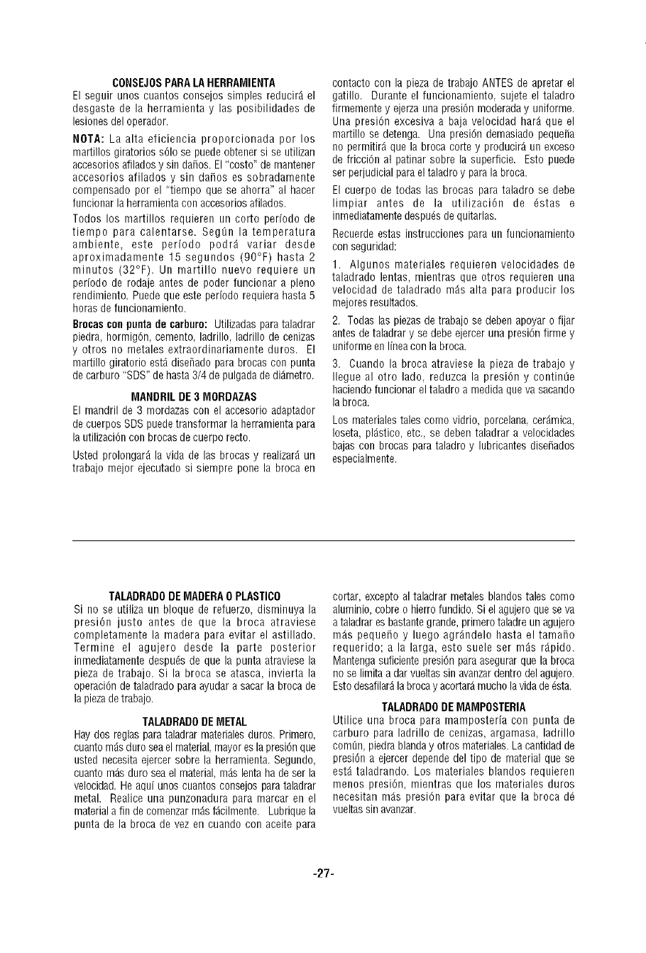
CONSEJOSPARALAHERRAMIENTA
El seguir unos cuantos consejos simples reducir_ el
desgaste de la herramienta y las posibilidades de
lesiones del operador.
NOTA: La alta eficiencia proporcionada por los
martillos giratorios s61ose puede obtener si se utilizan
accesorios afiladosy sin da_os. El"costo" de mantener
accesorios afilados y sin da_os es sobradamente
compensado por el "tiempo que se ahorra" al hacer
funcionar la herramienta con accesorios afilados.
Todos los martillos requieren un corto periodo de
tiempo para calentarse. Seg0n la temperatura
ambiente, este periodo podr9 variar desde
aproximadamente 15 segundos (90°F) hasta 2
minutos (32°F). Un martillo nuevo requiere un
periodo de rodaje antes de poder funcionar a pleno
rendimiento. Puede que este periodo requiera hasta 5
horas de funcionamiento.
Brocascon puntade carburo: Utilizadas parataladrar
piedra, horrnig6n, cemento ladrillo ladrillo de cenizas
y otros no metales extraordinariamente duros. El
martillo giratorio est9 disenado para brocas con punta
de carburo "SDS" de hasta 3/4 de pulgada de di_metro.
MANDRIL DE 3 MORDAZAS
El mandril de 3 mordazas con el accesorio adaptador
de cuerpos SDS puedetransformar la herramienta para
la utilizaci6n con brocas de cuerpo recto.
Usted prolongar_ la vida de las brocas y realizar_ un
trabajo mejor ejecutado si siempre pone la broca en
contacto con la pieza de trabajo ANTESde apretar el
gatillo. Durante el funcionamiento, sujete el taladro
firmemente y ejerza una presi6n moderada y uniforme.
Una presi6n excesiva a baja velocidad hard que el
martillo se detenga. Una presi6n demasiado pequena
no permitird que la broca corte y producir_ un exceso
de fricci6n al patinar sobre la superficie. Esto puede
ser perjudicial para el taladro y parala broca.
El cuerpo de todas las brocas para taladro se debe
limpiar antes de la utilizaci6n de 6stas e
inmediatamente despu6s de quitarlas.
Recuerde estas instrucciones para un funcionamiento
con seguridad:
1. Algunos materiales requieren velocidades de
taladrado lentas, mientras que otros requieren una
velocidad de taladrado rods alta para producir los
mejores resultados.
2. Todas las piezas de trabajo se deben apoyar o fijar
antes de taladrar y se debe ejercer una presi6n firme y
uniforme en linea con la broca.
3. Cuando la broca atraviese la pieza de trabajo y
Ilegue al otro lado, reduzca la presi6n y contin0e
haciendo funcionar el taladro a medida que va sacando
la broca.
Los materiales tales como vidrio, porcelana, cerdmica,
Ioseta, pldstico, etc., se deben taladrar a velocidades
bajas con brocas para taladro y lubricantes dise_ados
especialmente.
TALADRADODE MADERA0PLASTICO
Si no se utiliza un bloque de refuerzo, disminuya la
presi6n justo antes de que la broca atraviese
completamente la madera para evitar el astillado.
Termine el agujero desde la parte posterior
inmediatamente despu6s de que la punta atraviese la
pieza de trabajo. Si la broca se atasca, invierta la
operaci6n de taladrado paraayudar a sacar la broca de
la piezade trabajo.
TALADRADODEMETAL
Hay dos reglas para taladrar materiales duros. Primero,
cuantorodsduro seael material, mayor esla presi6n que
usted necesita ejercer sobre la herramienta. Segundo,
cuanto m_s duro sea el material, m_s lentaha de ser la
velocidad. Heaquf unos cuantos consejos parataladrar
metal. Realice una punzonadura para marcar en el
material a fin de comenzar m4s f4cilmente. Lubrique la
punta de la broca de vez en cuando con aceite para
cortar, excepto al taladrar metales blandos tales como
aluminio, cobre o hierro fundido. Si el agujero que se va
a taladrar es bastantegrande, primero taladre un agujero
m_s peque_o y luego agr4ndelo hasta el tamafio
requerido; a la larga, esto suele ser m_s r4pido.
Mantengasuficiente presi6n paraasegurar que la broca
no se limita a dar vueltassin avanzardentro del agujero.
Estodesafilar_la brocay acortar_mucho la vida dedsta.
TALADRADODEMAMPOSTERIA
Utilice una broca para mamposteria con punta de
carburo para ladrillo de cenizas, argamasa, ladrillo
com0n, piedrablanda y otros materiales. La cantidad de
presi6n a ejercer depende del tipo de material que se
est4 taladrando. Los materiales blandos requieren
menos presi6n, mientras que los materiales duros
necesitan m4s presi6n para evitar que la broca dd
vueltas sinavanzar.
-27-
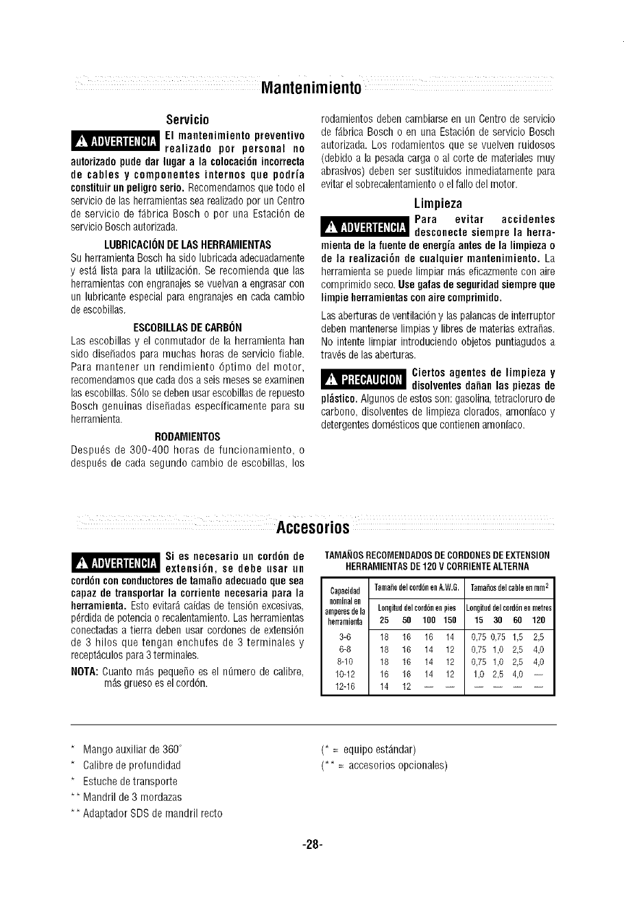
Servicio
EI mantenimiento preventive
realizado per personal no
autorizadopude dar lugar a la colocaci6nincorrecta
de cables y componentes internes que podria
constitoirun peligro serio. Recomendamosque todo el
servicio de las herramientassea roalizadoper un Centre
de servicio de f_brica Bosch o per uoa Estaci6n de
servicio Bosch autorizada.
LUBRICACI()NDELASHERRAMIENTAS
Su herramientaBosch ha side lubricada adecuadamente
y estA lista para la utilizaci6n. Se recomienda que las
herrarnientascon engranajesse vuelvana engrasar con
un lubricante especial para engranajes en cada cambio
de escobillas.
ESCOBILLASDECARBON
Las escobillas y el conmutador de la herrarnienta han
side disefiados para muchas horas de servicio fiable.
Para mantener un rendimiento 6ptimo del motor,
recomendamosque cada dos a seis mesesse examinen
lasescobillas.%1o sedeben usar escobillasde repuesto
Bosch genuioas disefiadas especificamente para su
herramienta.
RODAMIENTOS
Despots de 300-400 horas de funcionamiento, o
despu_s de cada segundo cambio de escobillas, los
rodamientos debencambiarse en un Centre de servicio
de fAbrica Bosch o en una Estaci6n de servicio Bosch
autorizada. Los rodamientos que se vuelven ruidosos
(debido a la pesada carga o al corte de materiales muy
abrasives) deben ser sustituidos inmediatamente para
evitarel sobrecalentamientoo elfallo del motor.
Limpieza
Para evitar accidentes
desconecte siempre la herra-
mienta de la fuente de energia antes de la limpieza o
de la realizaci6n de cualquier mantenimiento. La
herramienta se puede limpiar m_s eficazmentecon aire
comprimido seco.Use galas de seguridad siempre gun
limpie herramientascell aire comprimido.
Las aberturasde ventilaci6ny las palancasde interruptor
deben mantenerselimpias y libres de materias extrafias.
No intente limpiar introduciendo objetos puntiagudosa
travdsde las aberturas.
_ iertos agentes de limpieza y
disolventesdanan las piezas de
pl;_stico. Algunos de estos son: gasolina,tetracloruro de
carbono, disolventes de limpieza clorados amonfaco y
detergentesdom_sticos que contienenamoniaco.
Si es necesario on cord6n de
extensi6n, se debe usar nn
cord6nconcondnctoresde tamafioadecoado que sea
capaz de transportarla corriente necesaria para la Cnpacidad
herramienta.Esto evitar_ caidas de tensi6n excesivas nominalen
amperesdela
p_rdidade potenciao recalentamiento.Lasherramientas herrnmienta
conectadas a tierra deben usar cordones de extensi6n
de 3 hilos que tengan enchufes de 3 terminales y 3-6
6-8
recept_culospara3 terminales. 8-1o
NOTA:Cuanto m_s pequefio es el n_mero de calibre. 10-12
m_sgrueso osel cord6n. 12-16
TAMANOSRECOMENDADOSDECORDONESDEEXTENSION
HERRAMIENTASDE120V CORRIENTEALTERNA
TamahodelnordbnenA.W.G. Tamalesdelcableenmmn
Longiteddelnordbnenpies
25 50 100 150
18 16 16 14
18 16 14 12
18 16 14 12
16 16 14 12
14 12
_ongiteddelnordbnenmetres
15 30 60 120
0,75 0,75 1,5 2,5
0,75 1,0 2,5 4,0
0,75 1,0 2,5 4,0
1,0 2,5 4,0 --
*Mango auxiliar de 360°
*Calibrede profundidad
*Estuchede transporte
** Mandril de 3 mordazas
** Adaptador SDS de mandril recto
(* =equipo est_ndar)
(** = accosorios opcionales)
-28-

Notes:
-29-

Remarques:
-30-

Notas:
-31-

LIMITED WARRANTY OF BOSCH PORTABLE AND BENCHTOP POWER TOOLS
Robert Bosch Tool Corporation ("Seller") wari_nts to the original purchaser only, that all BOSCH portable and benchtop power tools will be free from
defects in material or workmanship for a period of one year from date of purchase. SELLER'S SOLEOBLIGATION AND YOUREXCLUSIVE REMEDY
under this Limited Wangn_ and, to the extent permitted by law, any warranty or condition implied by law, shall be the repair or replacement of parts,
without charge, wi_ici_are defective in material or workmanship and which have not been misused, carelessly handled, or misrepaired by persons
other tban Seller or Authorized Service Station. To make a claim under this Limited Warranty, you must return the complete portable or benchtop
power tool product, transportation prepaid, to any BOSCHFacton/Service Center or Authorized Service Station. For Authorized BOSCH Power Tool
Service Stations, please reter to your phone directory.
THiS LiMiTED WARRANTY DOES NOT APPLY TO ACCESSORY ITEMS SUCH AS CIRCULAR SAW BLADES, DRILL BITS, ROUTER BITS, JIGSAW
BLADES, SANDING BELTS, GRINDING WHEELS AND OTHER RELATED iTEMS.
ANY iMPLIED WARRANTIES SHALL BE LIMITED iN DURATION TO ONE YEAR FROM DATE OF PURCHASE.SOME STATES iN THE U.S., SOME
CANADIAN PROVINCESDO NOT ALLOW LIMITATIONS ON HOW LONG AN iMPLIED WARRANTY LASTS, SO THE ABOVE LIMITATION MAY NOT
APPLY TO YON.
IN NO EVENTSHALL SELLER BE LIABLE FOR ANY INCIDENTAL OR CONSEQUENTIAL DAMAGES (INCLUDING BUT NOT LIMITED TO LIABiLiTY
FORLOSS OF PROFITS)ARISING FROM THE SALE OR USE OF THiS PRODUCT. SOME STATES IN THE U.S. AND SOME CANADIAN PROVINCES
DO NOT ALLOW THE EXCLUSION OR LIMITATION OF INCIDENTAL OR CONSEQUENTIAL DAMAGES, SO THE ABOVE LIMITATION OR
EXCLUSIONMAY NOT APPLY TO YOU.
THIS LIMITED WARRANTY GIVES YOU SPECIFIC LEGAL RIGHTS,AND YOU MAY ALSO HAVE OTHER RIGHTS WHICH VARY FROM STATE TO
STATE iN THE U.S., PROVINCE TO PROVINCE IN CANADA AND FROM COUNTRYTO COUNTRY.
THIS LIMITED WARRANTY APPLIES ONLY TO PORTABLEAND BENCHTOP ELECTRICTOOLS SOLD WITHIN THE UNITED STATESOF AMERICA,
CANADA AND THE COMMONWEALTH OF PUERTO RICO. FOR WARRANTY COVERAGE WITHIN OTHER COUNTRIES, CONTACT YOUR LOCAL
BOSCHDEALER ORIMPORTER.
GARANTIE LIMITI_E DES ODTILS t:LECTRIQUES PORTATIFS ET D'ETABLI BOSCH
Robert Boscb Tool Corporation (le ,, vendeur ,,) garantit a I'acheteur b_itial seulement que tousles outiis _lectriques portatifs et d'ittabii BOSCH
seront exempts de vices de mat6daux ou d'exitcution pendant une pitriode d'un an depuis la date d'achat. LA SEULE OBLIGATION DU VENDEUR ET
LE SEUL RECOURS DE L'ACNETEURsous la pritsente garantie limitite, et en autant que la Ioi le permetta sous toute garantie ou condition implicite
qui en d6coulerait, sera rohligation de remplacer ou ritparer gratuitement les pieces d_fectueuses mat6dellement ou comme fabrication, pourvu que
lesdites d6fectuosit_s ne soient pas attdbuables & un usage abusif ou a quelque r@aration bricol6e par quelqu'un d'autre que le vendeur ou le
personnel d'une station-service agr_6e. Pour pr6senter une r6clamation en vertu de cette garantie limitee, vous devez renvoyer I'outil _lectdque
portatif ou d'6tabli complet, port payS, a tout centre de service agr_6 ou cenh_ de service usine. Veuillez consulter votre annuab_ t61@honique
pour lesadresses.
LA PRESENTEGARANTIE NE S'APPLIQUE PAS AUX ACCESSOIRESTELS QUE LAMES DE SCIES CIRCNLAIRES, MECHES DE PERCEUSES,FERS
DE TOUPIES, LAMES DE SCIES SAUTENSES, COURROIES DE PONOAGE,MEULES ET AUTRESARTICLES DN GENRE.
TOUTE GARANTIE IMPLICITE SERA LIMITEE COMME DUREE A UN AN A COMPTER DE LA DATE D'ACHAT. CERTAINS ETATS AMERICAINS,
CERTAINES PROVINCES CANADIENNES N'ADME_FANT PAS LE PRINCIPE DE LA LiMiTATION DE LA DUREE DES GARANTIES IMPLICITES, IL
EST POSSIBLE QUE LES LIMITATIONS CI-DESSUS NE S'APPLIQUENT PAS A VOTRE CAS.
EN AUCUN CAS LE VENDEURNE SAURAIT ETRE TENU POUR RESPONSABLE DES iNCIDENTS OU DOMMAGES INDIRECTS (INCLUANT, MAIS NE
SE LIMITANT PAS AUX PERTES DE PROFITS) CONSECNTIFS A LA VENTE OU L'USAGE DE CE PRODUIT. CERTAINS ETATS AMERICAINS ET
CERTAINES PROVINCES CANADIENNES N'ADME_FANT PAS LE PRINCIPE DE LA LiMiTATiON NI L'EXCLUSION DESDOMMAGES INDIRECTS ET
CONSEQUENTIELS,IL EST POSSIBLE QUELES LiMiTATIONS ON EXCLUSIONS CI-DESSUS NE S'APPLIQUENT PAS A VOTRE CAS.
LA PRESENTE GARANTIE VOUS ACCORDE DES DROITS BIEN DETERMINES, Y COMPRIS POSSIBLEMENT CERTAINS DROITS VARIABLES DANS
LES DIFFERENTS ETATS AMERICAINS, PROVINCES CANADIENNE ET DE PAYS A PAYS.
CE_FE GARANTIE LIMITEE NE S'APPLIQNE QU'AUX OUTILS ELECTRIQUES PORTATIFS ET D'ETABLI VENDUS AUX ETATS-NNIS D'AMERIQNE,
AU CANADA ET AN COMMONWEALTH DE PORTO RICO. POUR COUVERTURE DE GARANTIE DANS LES AUTRES PAYS, CONTACTEZ VOTRE
IMPORTATENROU REVENDEURBOSCH LOCAL.
GARANTIA LIMITADA PARA HERRAMIENTAS MECANICAS PORTATILES Y PARA TABLERO DE BANCO BOSCH
Robert Bosch Tool Corporation ("el Vendedor") garantiza, itnicamente al comprador original, que todas las lmrramientas mecdnicas portdtiles y
para tablero de banco BOSCH estarAn libres de defectos de material o de fabricaci6n durante un perfodo de un abo a partir de la fecha de compra.
LA UNICA OBLIGACION DEL VENDEDOR Y EL RECURSO EXCLUSIVO QUE USTED TIENE bajo esta Garantia Limitada y, hasta donde la ley Io
permita, bajo cualquier garantia o condici6n implicita por ley, consistir_ en la reparaci6n o sustituci6n sin costo de las piezas que presenten
defectos de material o de fabdcaci6n y que no hayan sido utilizadas incorrectamente, manejadas descuidadamente o reparadas incorrectamente
por personas que no sean el Vendedor o una Estaci6n de servicio autodzada. Para efectuar una reclamaci6n bajo esta Garantia Limitada, usted
debe devolver el producto, que consiste en la herramienta mecanica port_til o para tablero de banco completa, con el transporte pagado, a
cualquier Centro de servicio de f_brica o Estaciitn de servicio autorizada. Para Estaciones de servicio autodzadas de herramientas mecanicas
BOSCH, por favor, consulta el directorio telef6nico.
ESTA GARANTIA LIMITADA NO SE APLICA A ARTICULOS ACCESORIOS TALES COMO HOJAS PARA SIERRAS CIRCULARES, BROCAS PARA
TALADROS, BROCAS PARA FRESADORAS, HOJAS PARA SIERRAS DE VAIVEN, CORREAS PARA WAR, RUEDAS DE AMOLAR Y OTROS
ARTICULOS RELACIONADOS.
TODAS LAS GARANTIAS IMPLICITAS TENDRAN UNA DURACION LIMITADA A UN ANO A PARTIR DE LA FECHA DE COMPRA. ALGUNOS
ESTADOS DE LOS EEAJU. Y ALGUNAS PROVINCIAS CANADIENSES NO PERMITEN LIMITACIONES EN CUANTO A LA DURACION DE UNA
GARANTIA IMPLICITA, POR LO QUE ES POSIBLEQUE LA LIMITACION ANTERIOR NO SEA APLICABLE EN EL CASO DE USTED.
EL VENDEDOR NO SERA RESPONSABLE EN NINGUN CASO DE NINGUN DANO iNCIDENTAL 0 EMERGENTE(INCLUYENDO PERO NO LIMITADO
A RESPONSABILIDAD POR PERDIDA DE BENEFICIOS) QUE SE PRODUZCA COMO CONSECUENCIA DE LA VENTA 0 UTILIZACION DE ESTE
PRODUCTO. ALGUNOS ESTADOS DE LOS EE.UU. Y ALGUNAS PROVINCIAS CANADIENSES NO PERMITEN LA EXCLUSION 0 LIMITACION DE
LOS DA[_JOSINCIDENTALES 0 EMERGENTES, POR LO QUE ES POSIBLE QUE LA LIMITACION 0 EXCLUSION ANTERIOR NO SEA APLICABLE EN
EL CASO DE USTED.
ESTA GARANTIA LIMITADA LE CONFIERE A USTED DERECHOSLEGALES ESPECIFICOS YES POSIBLE QNE USTED TAMBIEN TENGA OTROS
DERECHOSQUEVARIAN DE ESTADOA ESTADOEN LOS EE.UU., DE PROVINCIAA PROVINCIAEN CANADAY DE UN PAlS A OTRO.
ESTA GARANTIA LIMITADA SE APLICA SOLAMENTE A HERRANIENTAS ELECTRICASPORTATILES Y PARA TABLERO DE BANCO VENDIDAS EN
LOS ESTADOS UNIDOS DEAMERICA, CANADA Y EL ESTADOLIBRE ASOCIADODE PUERTO RICO. PARA COBERTURA DE GARANTIA EN OTROS
PAISE& PONGASEEN CONTACTO CON SN DISTRIBUIDOR 0 IMPORTADOR LOCAL DE BOSCH.
© Robert Bosch Tool Corporation 1800 W. Central Road Mt. Prospect, IL 60056 -2230
Exportado por: Robert Bosch Tool Corporation Mt. Prospect, IL 60056 -2230, EU.A.
Importado en M6xico por: Robed Bosch, S.A. de C.V., Calle Robed Bosch No. 405, Zona Industrial,
Toluca, Edo.de M6xico, C.P. 50070, Tel. (722) 2792300
1 619 929 654 10/04 Printed in Germany
