Bosch AN PAVIRO Factory System V1_1x Application Note (PAVIRO V1.1) De En US 33215889931
User Manual: Bosch Application note (PAVIRO Factory System v1.1) PVA-4CR12 Controller
Open the PDF directly: View PDF ![]() .
.
Page Count: 5

1 | Application Note | Public Address | PAVIRO Factory Default System
PAVIRO Factory Default System
This application note describes the functions, installation and operation of this system.
Component list:
A basic system consists of:
1x PVA-4CR12 Controller
1x PVA-2P500 Amplifier
1x PVA-15CST Call Station
1x 24V/2A Power supply
System features:
12 loudspeaker zones via 2 router clusters
For each router cluster (zone 1-6 and zone 7-12) 500W loudspeaker load can be
connected
Selective announcement to each of the 12 loudspeaker zones via the call station
A background music (program) source can be selectively activated by the call station
into each loudspeaker zone (option)
Maximum two audio signals can be activated simultaneously, but only one signal per
router cluster
The English EVAC-message "incident" can be triggered by a contact (option)
A logical output is provided to mute external systems when an announcement or
EVAC-message is active (option)
Bosch Security Systems | Public Address
BhS it
St
|
Pbli Add
Bosch Security Systems | Public Address
Application Note
PAVIRO Factory Default System
- v1.0

2 | Application Note | Public Address | PAVIRO Factory Default System
Block Diagram:
System Behavior:
The system has to be operated with the call station PVA-15CST, only the evacuation is
triggered by an external normal open contact.
The operation of the call station is explained in the following figure:
3 | Application Note | Public Address | PAVIRO Factory Default System
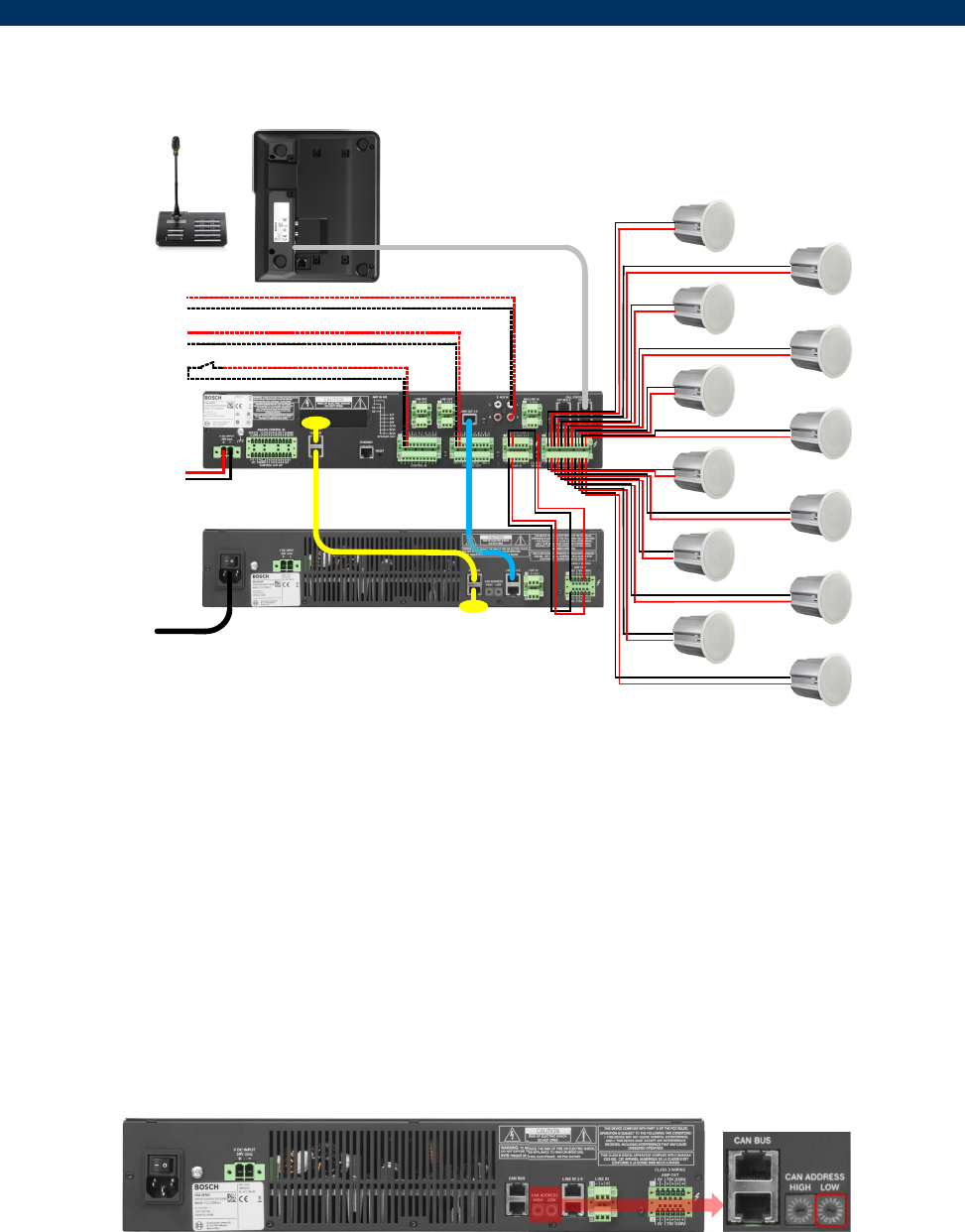
System installation:
termination
termination
Zone11
Mains
power
EVACstart/stop
24VDC
INPUT
Mutecontact
24V/200mA
Zone1
Zone3
Zone5
Zone7
Zone9
Zone12
Zone2
Zone4
Zone6
Zone8
Zone10
Programsource
Create the cabling as shown in the wiring diagram. Take in account the requirements in
the operation manuals PVA-4CR12 and PVA-2P500 in the chapter "Connections".
NOTE: Unused loudspeaker outputs do not have to be wired.
The CAN-BUS has to be terminated with the enclosed terminating resistors.
NOTE: It is not allowed to terminate the audio Line 1-4.
The connections drawn in dashed lines are optional and have to be wired only when the
respective function is used.
After finishing the cabling, the CAN address has to be set to "01" on the PVA-2P500
amplifier.
NOTE: Before the address is set, make sure the PVA-2P500 is disconnected from the
mains.
o Now the system can be connected to the power supply and activated.

4 | Application Note | Public Address | PAVIRO Factory Default System
o The address of the call station PVA-15CST must be set to "01".
This is done via the menu of the call station:
o To open the main menu, press the ▲ Button keep it held down and press the
▼button at the same time.
o Press the ▼ button until you reach the "CST Setup" menu item.
o After pressing the
↵
button, the "Input Password" dialog is showing.
o Press the button "2" (on the right side) four times and then the
↵
button.
o Press the ▼ Button, to navigate to the "CST Setup Menu" menu item and then
the
↵
button.
o The display shows “CAN Address”.
o Press the
↵
button.
o Change the address with the ▲ button from “0” to “1” and press then the
↵
button.
o Press twice the ESC button to exit the menu.
o The date and clock settings are done via the PVA-15CST call station menu
o To open the main menu, press the ▲ Button keep it held down and press the
▼button at the same time.
o Press the ▼ button until you reach the "Date / Time" menu item.
o After pressing the ↵ -button, the current date and time can be entered by using
the numeric keys 0-9.
o Press the
↵
button after the input and then the ESC button.
o The date / time display can also be switched off, by the menu of the call station PVA-
15CST.
o To open the main menu, press the ▲ Button keep it held down and press the
▼button at the same time.
o Press the ▼ button until you reach the "CST Setup" menu item.
o After pressing the
↵
button, the "Input Password" dialog is showing.
o Press the button "2" (on the right side) four times and then the
↵
button.
o Press the ▼ Button, to navigate to the "CST Setup Menu" menu item and then
the
↵
button.
o Press the ▼ button until you reach the "Show Date & Time" menu item.
o Press the
↵
button.
o Change the value with the ▲ button from “on” to “off” and press the
↵
button.
o Press twice the ESC button to exit the menu.
The system is ready for operation if all steps above are successful performed.

5 | Application Note | Public Address | PAVIRO Factory Default System
Fault description and their elimination:
The following table gives an overview of faults that may occur and how they can be
eliminated.
Explanation of the table
CST TEXT = The error text that is displayed in the PVA-15CST call station
DESCRIPTION = Description of this error type
ACTION = Actions to eliminate the fault
CST TEXT DESCRIPTION ACTION
Contr. Data Fault Memory or Read/Write error. Controller defect, must be repaired by ASA.
Watchdog Fault Watchdog error of the device. The system has
rebooted. Press the "System Fault" button on the call
station to reset the error.
Contr. SW Fault The device firmware version is not compatible
with the IRIS-Net version used. A firmware update of the Controller is necessary.
Contr. HW Fault Error in the power supply or the A/D converters
of the device. Controller defect, must be repaired by ASA.
Temperature Fault Temperature overload of the device. The internal temperature of the controller is too
high. Ensure sufficient cooling.
DSP System Fault Error during the processing of audio data. Controller defect, must be repaired by ASA.
Message Fault Collected Error of the message manager. Further details are provided in the message
manager dialog (ERROR STATES).
CAN Bus Fault Fault condition on the CAN bus (Amplifier and
Router communication). Further details are provided in the Interface
dialog (CAN INTERFACE).
CST Bus Fault #%u Fault condition on the CST bus (call station
communication). The parameter %u gives the
slot number of the erroneous module.
Check cable connections between the call
station and call station port.
Int.Router DSP Fault Error in the digital signal processing (DSP) of the
device. Controller defect, must be repaired by ASA
Int.Router HW Fault Hardware error. Controller defect, must be repaired by ASA
Int.Router TMP Fault Temperature overload of the device. The internal temperature of the controller is too
high. Ensure sufficient cooling.
Int.Router PLT Fault Missing pilot tone at input 1 of cluster A. Check cable connections between amplifier
output and AMP-IN 1 cluster A.
Int.Router PLT Fault Missing pilot tone at input 1 of cluster B. Check cable connections between amplifier
output and AMP-IN 1 cluster B.
CST Fault #%u
A connected PVA-15CST call station has
transferred an error message. The parameter
%u gives the address of the erroneous call
station.
Further details are provided in the PVACST
dialog (Supervision).
Amplifier Fault #%u A connected PVA-2P500 power amplifier has
transferred an error message. The parameter
%u gives the address of the erroneous amplifier.
Further details are provided in the PVAAMP
dialog (Supervision).
