Bosch F01U263663 04_DS938Z_ING Installation Manual ([DS938Z]) DS938Z In Guide En US 2629796875
User Manual: Bosch Installation Manual ([DS938Z]) DS938Z and ZX938Z Series Panoramic PIR Detectors
Open the PDF directly: View PDF ![]() .
.
Page Count: 6
Bosch Security Systems, Inc. product manufacturing dates
Use the serial number located on the product label and refer to the Bosch
Security Systems, Inc web site at: http://www.boschsecurity.com/datecodes/.
© 2013 Bosch Security Systems, Inc. 130 Perinton Parkway Fairport, NY 14450
en Installation Guide
Ceiling Mount
PIR Detector with Self-Test
DS938Z
2 © 2013 Bosch Security Systems, Inc.
EN 50131-2-2 Grade 2
EN 50130-5 Environmental Class II
IP30 IK04 (EN 60529, EN 62262)
0 - 95% Relative Humidity
(0 - 85% UL Installations)
-29°C to +50°C
(-20°F to +120°F )
UL Listed
installations,
the temperature
range is 0°C to +50°C
(+32°F to +120°F)
SELV
Connect all wiring to a safety extra-low voltage (SELV) circuit only.
Ligue todas as cablagens apenas a um circuito de segurança de tensão extra baixa (SELV).
Conecte el cableado únicamente a un circuito de seguridad para voltajes muy bajos (SELV).
Alle Drähte sind ohne Ausnahme an Niederspannung anzuschließen.
Sluit alle bedrading uitsluitend aan op een circuit met een extra lage veiligheidsspanning.
Prenez soin de connecter tous les câbles à un circuit à très basse tension de sécurité (TBTS).
Collegare tutti i cavi esclusivamente a un circuito SELV (circuito di sicurezza a bassissima tensione).
Changes or modifi cations not expressly approved
by Bosch Security Systems, Inc. can void the user’s
authority to operate the equipment.
UL
Perform Walk Test at least once a year.
Use only a Listed limited-power source.
The Listed control unit or a Listed burglary power
supply must provide 4 hours (20 mAh) of standby
power.
Install the unit in accordance with National
Electrical Code NFPA 70.
Adjust the microwave range control, if necessary, to
achieve maximum range.
Trademark names are used throughout this document. In most cases, these designations are claimed as
trademarks or registered trademarks in one or more countries by their respective owners. Rather than
placing a trademark symbol in every occurrence of a trademark name, Bosch Security Systems, Inc.
(hereinafter referred to as Bosch) uses the names only in an editorial fashion and to the benefi t of the
trademark owner with no intention of infringing the trademark.
Region Certifi cation
Europe CE EN50131-2-2, Grade 2
EN50130-5 Environmental Class II
AFNOR 2620001760A1
Poland TECHOM 98/07 Klasy "C"
USA UL ANSR: Intrusion Detection Units
(UL639)
Sweden INTYG 04-683
2 boucliers NF324 - H58
Autosurveillance à l’ouverture
Immunité champ magnétique
Test sans masque de vision verticale
et sans immunité aux animaux
www.afnor.org
www.cnpp.com
Certifi cat NF A2P 2620001760A1
F.01U.263.663 | 04 | 2013.04 | 11
7.2 Selecting the Optical Module
1. For ceilings between 8 and 13 ft. (2.4 and 4.0 m) from the fl oor, use
the optical module marked AR8-13. This marking can be found next to
the two optical module tabs.
2. For ceilings between 13 and 18 ft. (4.0 and 5.5 m) high, use the optical
module marked AR13-18.
3. To replace an optical module, push the optical module tabs towards
the center until the module snaps free of the circuit board. Holding the
new module by the tabs, snap the new module into place.
NOTICE!
Avoid fi ngerprints on the mirrored surfaces. Should the mirrored sur-
faces become soiled or otherwise marked, they can be cleaned using a
soft, clean cloth and any commonly available, mild window cleaner.
321 123
4
5
BASEBOARD HEAT
AR8-13
AR8-13
432154321
MASK 3
SECTORS
WINDOW
AR8-13
AR8-13
4321 5 432 1
MASK 15
SECTORS
WINDOW
1123
4
5
BASEBOARD HEAT
NOTICE!
When replacing the mirror, make sure it is facing the same
direction as before it was removed.
4. Replace the enclosure onto the base.
5. Close cover and turn clockwise to secure.
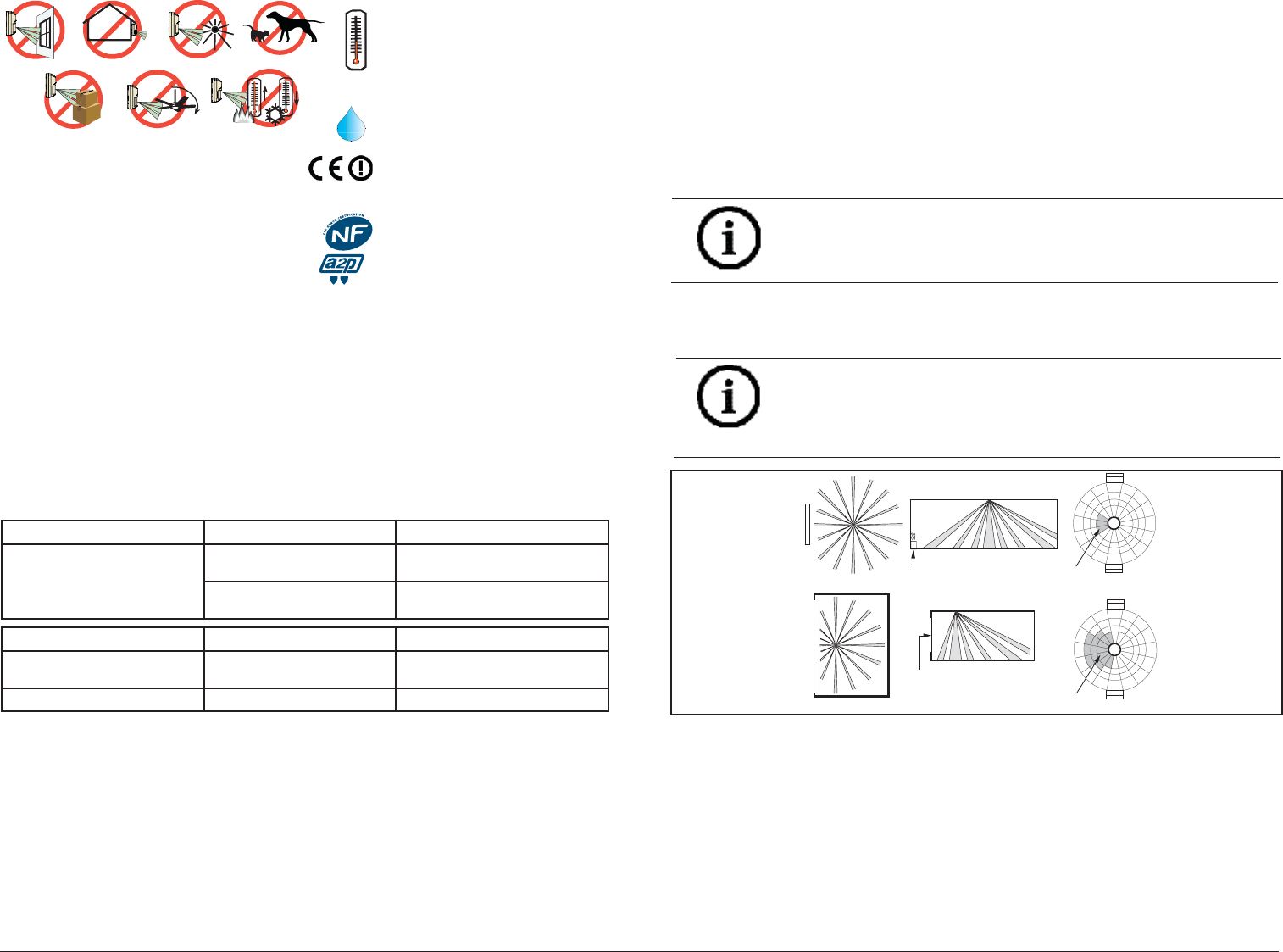
8 Coverage
• 360° by 60 ft. (18.3 m) diameter coverage when mounted on 8 to 18 ft
(2.4 to 5.5 m) high ceilings.
• The coverage pattern consists of 64 zones grouped into 16 barriers,
with one additional zone looking straight down from the unit
(sabotage). Each barrier is 30 ft (9.2 m) long and 4.4 ft. (1.3 m) wide
at 30 ft (9.2 m).
• The DS9382 comes with a choice of two optical modules. Refer to
Section 5.1 to determine the best module for on ceiling height.
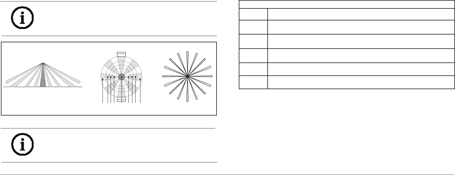
Figure 7.2: Masking
10 © 2013 Bosch Security Systems, Inc.
If the time period selected has elapsed from the last alarm, the LED will
fl ash two times and the Trouble Output will activate.
Setting the Motion Monitor timer to shorter periods can be used to force a
protection walk test of remotely located zones.
It is recommended that the 30 day timer be selected. This verifi es that
the unit is operational and avoids nuisance trouble conditions caused by
holidays, vacations, etc.
NOTICE!
When attempting to remove any masking, many adhesives will either
destroy the mirror surface or leave enough residue behind to reduce
coverage performance.
M-
4
AR8-13
AR8-13
D
432143125
AB
PC
E
F
G
H
I
J
N
O
K
L
M
A
B
C
D
E
F
G
H
I
J
K
L
M
N
O
P
M-3 M-2 M-1 E-1 E-2 E-3
E-4
5
Figure 7.1: Mirror module to pattern reference
7 Optical Module
7.1 Optical Module Masking
Peel-off masks are provided with the unit for each segment of the
optical module to allow for customized coverage, or to block out areas
of objects that may cause thermal disturbances. The mask is self-
adhesive and pre-cut in the shape of the optical module.
The location of the zone to be masked depends on the position of the
detector. Therefore, determine the mirror surface to be masked before
removing the mirror from the detector.
To block out a particular zone or group of zones, peel off a section of
the mask that corresponds to the appropriate zone, and stick it on the
mirror segment. Before attempting any masking, be sure the chosen
mirror surface is the correct one. Refer to Figure 7.1 to identify mirror
segments and zones.
NOTICE!
When disabling the look-down segment, do not mask segment 5
directly as this will disable the entire detector. Instead, mask the
segment on the dome directly below segment 5.
F.01U.263.663 | 04 | 2013.04 | 3
1 Overview
The DS938Z is a high performance passive infrared intrusion detector.
It is equipped with advanced PIR detection and supervision circuits and
is designed to provide an alarm condition upon detection of an intruder
passing through its area of coverage.
Employing balanced dual-opposed sensing elements, the DS938Z passive
infrared (PIR) detector makes use of the fact that all objects give off (emit)
infrared energy, and that the warmer an object is, the greater the amount
of infrared energy given off. The DS938Z uses PIR receiver technology
designed to detect the change in infrared energy caused when a target of a
different temperature from a stable background passes through its fi eld of
coverage.
The coverage pattern consists of sensor zones arranged to form a circular
coverage pattern.
Using Motion Analyzer II circuitry, the detector must fi rst see a change
in infrared energy in one zone followed by a change of energy in the
remaining zone. Therefore, disturbances that occur in only one fi nger do
not constitute motion and are ignored. This “catch sensitivity” may be
changed in the fi eld by the installer to provide the degree of sensitivity
required by the installation.
Self-test and supervision circuits provide reliable operation in a variety of
installation environments. The result is a highly advanced detector offering
superior performance with freedom from false alarms.
Specifi cations
Dimensions
(HxDia) 3.5 in. x 5.25 in. (8.9 cm x 13.3 cm)
Input
Power 6.0 to 15.0 VDC; 5 mA standby, 20 mA in alarm with LEDs enabled. Use only an Approved
Limited Power Source.
Alarm Relay Silent-operating Form “C” relay. Contacts rated <100 mA, 25 VDC, 2.5W maximum, <20
Ohm closed for DC resistive loads.
Tamper Contacts rated at 28 VDC, 125 mA maximum, <1 Ohm. Connect tamper circuit to a 24-
hour protection circuit.
Trouble
Output Maximum current load is 25 mA.
Optional
Accessory TC6000 test cord.
4 © 2013 Bosch Security Systems, Inc.
Figure 2.1: Coverage Pattern
Optical module Interface connector
Cover twist tabs (4)
Test lead
cutout
Enclosure release openings (2)
Anti-vandal
locking screw
holes (2) Interface
pins
Enclosure release tabs
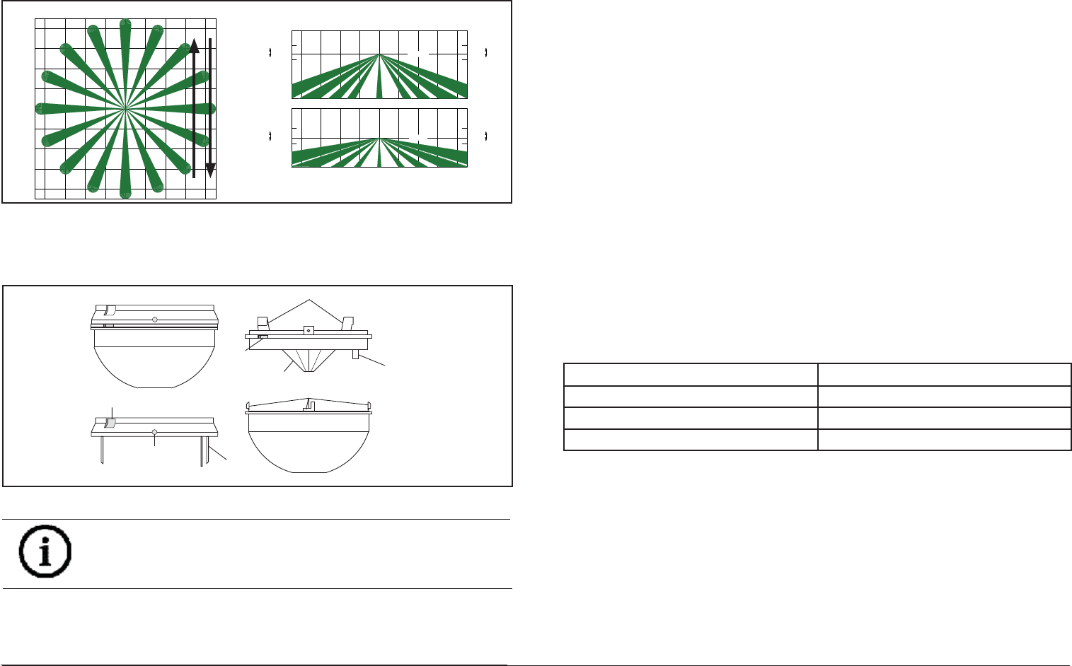
Figure 2.2: Opening cover
NOTICE!
Slightly rock the enclosure side-to-side during removal to overcome the
friction caused by the base-to-enclosure terminal pins.
1. Remove the base from the enclosure by pressing the two enclosure
release tabs inward while lifting the enclosure away from the base.
Refer to Figure 2.2.
9 m
8 m
6 m
4 m
2 m
0 m
2 m
4 m
6 m
8 m
9 m 30 ft
26 ft
20 ft
13 ft
7 ft
0 ft
7 ft
13 ft
20 ft
26 ft
30 ft
30 ft
26 ft 20 ft 13 ft 7 ft 0 ft 7 ft 13 ft 20 ft 26 ft
30 ft
≤5.5 m
≥4.0 m
4.6 m
0 m
≤4.0 m
3.0 m
≥2.4 m
0 m
9 m
8 m6 m4 m2 m0 m2 m4 m6 m8 m
9 m
0 ft
≥8 ft
10 ft
≤13 ft
0 ft
≥13 ft
15 ft
≤18 ft
AR13-18
AR8-13
2. Open the cover by turning counterclockwise.
3. Route wiring as necessary to the rear of the base and through the
center hole. Refer to Figure 2.3.
2 Mounting
Select a location likely to intercept an intruder moving beneath and across
the coverage pattern. Refer to Figure 2.1. Recommended mounting height
range is 8 to 18 feet (2.4 to 5.5 m).
The surface should be solid and vibration-free. (i.e. Drop tiles should
be secured if the area above the tiles is used as an air return for HVAC
systems).
F.01U.263.663 | 04 | 2013.04 | 9
6.2 False Alarm Prevention
Turn on all heating and cooling sources that would normally be in
operation during times of protection. Stand away from the unit and
outside the coverage pattern, then monitor the background noise for at
least three minutes.
Readings should not deviate from the reference level more than ±0.15
VDC. For readings outside these limits; eliminate the cause, rotate the unit
slightly, or mask out the mirror segment(s) looking down at the thermal
disturbance.
6.3 Coverage Margin
Again walk across the farthest edge of required coverage.
A minimum voltage change of 1.0 VDC from the reference level is required
in the wintertime when the background temperature is cool. This will make
up for summertime, when the background is warmer. If testing the unit in
the summertime, the minimum recommended voltage change is 0.75 VDC.
When testing is completed, remove the TC6000 Test Cord, and twist-lock
the cover into place.
6.4 Supervision Feature
The DS938Z performs several supervision features that, combined with
the advanced motion detection capabilities of the detector, provide
an extremely high level of security. A supervision trouble condition is
indicated at the detector by the Alarm/Test LED (see the Supervision
Display Chart).
• The LED indicates the cause of the supervision trouble using coded
pulses. The supervision trouble signal activates the Trouble Output
available at terminal 8, which should be connected to a 24-hour zone.
The supervision features function as follows:
LED CAUSE
ON Unit alarm
2 Flashes Motion monitor time out
4 Flashes PIR self-test failure
PIR: The operation of the PIR is electronically checked approximately
every 12 hours. If the PIR fails, the Alarm/Test LED will fl ash four times and
the Trouble Output will activate.
Motion Monitor Supervision: This feature verifi es that the detector has a
clear view of the detection area and has not been blocked. When selected
using switches S4 and S5, a supervision timer is activated. A trouble
condition will be indicated if the detector has not alarmed at least once
during the selected time period (this feature can be disabled by placing
both switches in the Off position). The time period selected should be
long enough to allow adequate time for holiday weekends.
Refer to Section 4.0 Feature Selection for proper switch settings.
8 © 2013 Bosch Security Systems, Inc.
NOTICE!
The use of a Sonalert type device (sounder) will provide an audible tone
during the time the unit is in alarm. Of the three available connector
pins, the center pin is positive (+) with respect to either outside pin
(outside pins are common (-)).
Use of the sounder is intended only as an aid for walk testing during
installation.
3. Place the cover on the unit, and twist-lock it clockwise into place.
4. Apply power to the unit.
5. Wait at least two minutes, after applying power, to start walk tests.
6. The edge of the coverage pattern is determined when the Alarm/Test
LED indicator (and optional Sonalert®, if installed) fi rst turns on.
7. Walk test the unit from all directions to determine the boundaries.
8. After completion of the walk tests, remove the Sonalert® (if installed).
NOTICE!
Be sure the TC6000 and Sonalert leads are dressed through the
cutout.
NOTICE!
Walk testing should be done across the coverage pattern as shown.
6 Final Tests
6.1 Noise Measurement
1. Connect a 20,000 ohm/volt (or greater) DC VOM to the Noise Voltage
connector using the TC6000 as shown. Set meter scale for about 3.0
VDC.
2. The base reference level for reading background noise or target
voltages is approximately 2.0 VDC. Installations in quiet environments,
therefore, will result in a steady meter reading between 1.9 and 2.1
VDC. Look for areas and sources of thermal disturbances if the meter
fl uctuates greatly.
NOTICE!
Meter readings are very important in determining background
disturbance levels and catch margin sensitivity.
F.01U.263.663 | 04 | 2013.04 | 5
CAUTION!
Only apply power after all connections have been made and inspected.
Do not coil excess wiring inside detector.
Use no smaller than #22
AWG (0.8 mm) wire in the terminal strip.
CAUTION!
Be sure all wiring is unpowered (de-energized) before routing.
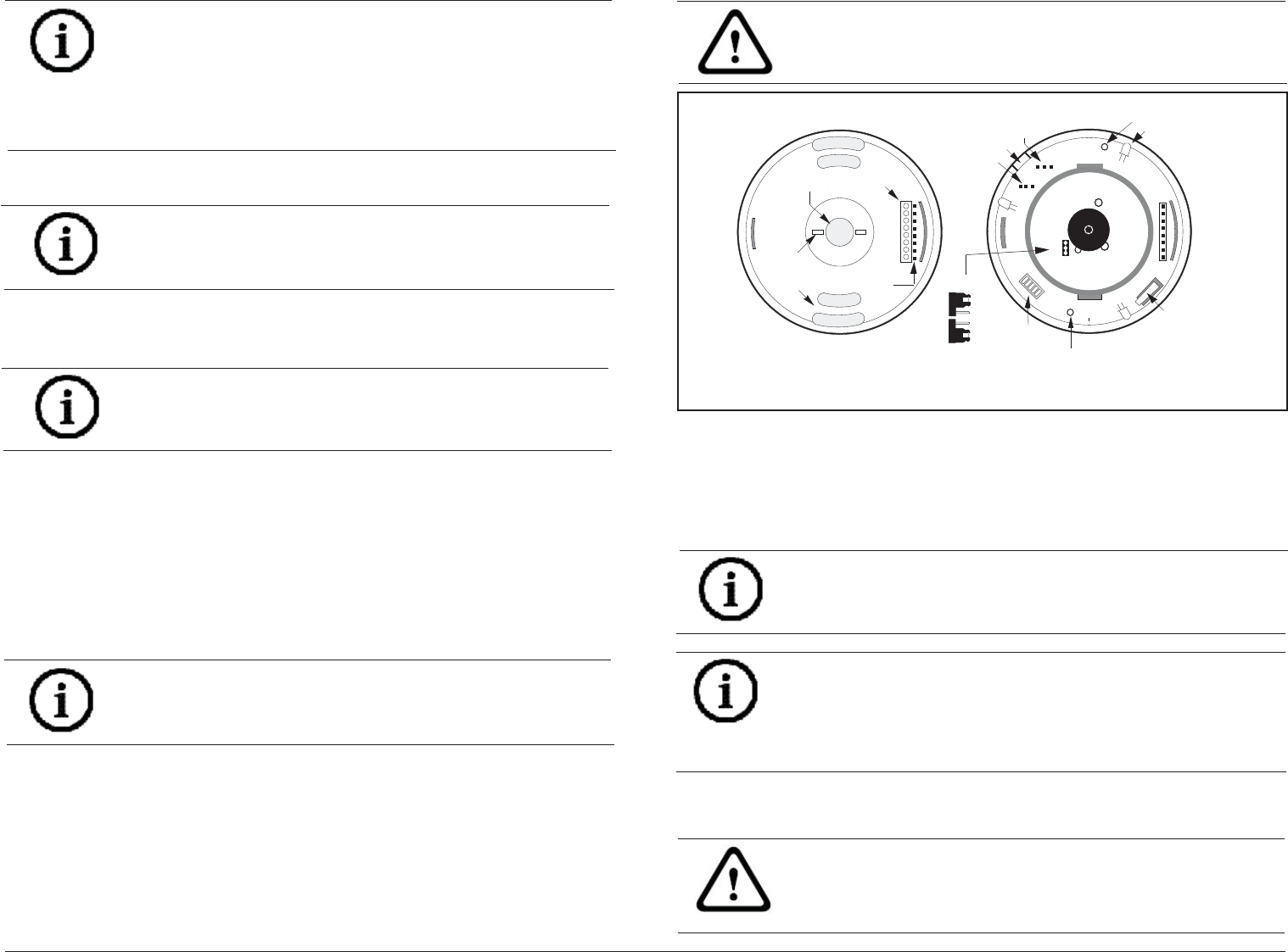
Mounting Base
REAR WIRE
ENTRANCE
WIRE
TIE-DOWNS (2)
TERMINAL
STRIP
INTERFACE
PINS
MOUNTING
SLOTS (4)
18
Top View of Enclosure
with Cover and Optical Module Removed
ALARM/TEST L
ED
INDICATOR (3
)
SOUNDER
NOISE
VOLTAGE
CONFIGURATION
SWITCHES
COVER
TAMPER
ON
OFF
TEST LEAD
CUTOUT
ANTI-TAMPER SCREW HOLE
REQUIRED FOR EN50131
INSTALLATIONS
ANTI-T AMPER SCREW HOLE
REQUIRED FOR EN50131
INST ALLATIONS
LO
HI
GAIN SELECT
JUMPER
HI
LO
NOTICE!
The DS938Z base will not completely cover a 4-inch square box. Where
aesthetics are important, a 4-inch octagonal box is recommended.
NOTICE!
Mounting to removable ceiling tiles is not recommended unless a
sandwich is made of the base, ceiling tile, and a back plate behind the
tile. Covers used for 4-inch octagonal and square boxes make a suitable
back plate (when used with bolts and wing nuts, as an example).
3 Wiring
Figure 2.3: Overview
4. Firmly mount the base. Depending on local regulations, the base may
be directly surface mounted using anchors, mollies, or wing-nuts, or
may be mounted to standard 4-inch octagonal or square electrical
boxes.
6 © 2013 Bosch Security Systems, Inc.
4.1 LED Operation
ON: Allows the Alarm/Test LED to operate when activated by
motion.
OFF: The LED will not operate on alarm activation, but will
indicate a supervision trouble condition.
4.2 Sensitivity Selection
Sensitivity modes depend on the type of coverage desired and the
installation environment.
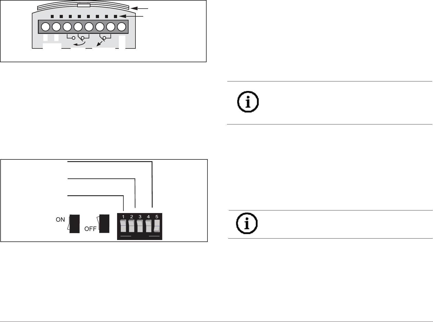
Figure 4.1: Selecting features
Figure 3.1: Wiring to terminals
Terminals 1 (-) & 2 (+): Power contacts.
Terminals 3 (NO), 4 (C), & 5 (NC): Alarm relay contacts. Use terminals 4
& 5 for Normally Closed circuits. Do not use with capacitive or inductive
loads.
Terminals 6 (T) & 7 (T): Normally Closed tamper contacts.
Terminal 8 (TR): Solid state Trouble output. Shorts to ground (-) when the
detector is in a Trouble condition.
4 Feature Selection
The DS938Z has several features that are controlled using the confi guration
switches.
}
}
1 ON = ON
1 OFF = OFF
LED
Sensitivity
Motion
Monitor
OPEN
4 ON and 5 OFF = 4 Day
4 OFF and 5 ON = 30 Day
4 OFF and 5 OFF = Disabled
2 ON and 3 OFF = High
2 OFF and 3 ON = Intermediate
2 ON and 3 ON = Standard
– +
RELAY
12345678
6to15
VDC Alarm
TROUBLE
INTERFACE
PINS
KEY GUI
DE
TAMPER
F.01U.263.663 | 04 | 2013.04 | 7
• Standard Sensitivity: Tolerates environment extremes on this setting,
but requires the largest amount of intruder motion to achieve an alarm.
• Intermediate Sensitivity: The recommended setting for most
installations. Use in locations where an intruder is expected to
cover only a small portion of the protected area. Tolerates normal
environments on this setting. The detector is shipped in Intermediate
Sensitivity mode.
• High Sensitivity: The setting for fast response to intruder signals. For
use only in extremely quiet environments where ceiling drafts, and
thermal and illumination transients are not anticipated.
If both switches are in the OFF position, the unit will default to the
intermediate setting.
4.3 Signal Gain
The DS938Z permits selection of the signal gain depending upon the
environment to be protected. The gain select jumper is located under the
optical module. Refer to Figure 2.3.
• High Gain: Recommended for large coverage applications up to 60
ft. (18.3 m) in diameter. The DS938Z is shipped in this setting. If
the gain select jumper is missing, the unit will default to High Gain.
• Low Gain: Recommended for applications where the area to be
covered is 40 ft. (12.2 m) or less in diameter and for applications
where High Gain may be too sensitive for environmental extremes.
NOTICE!
Setting the DS938Z for Low Gain reduces the coverage area to 40 ft.
(12.2 m) in diameter.
5 Setup and Walk Testing
1. Attach a TC6000 Test Cord to the Noise Voltage terminals. Since the
outside terminals are common, polarity is not important and the black
lead may be toward or away from the optical module.
2. Attach a Sonalert to the sounder pins at this time if one will be used
during walk testing.
NOTICE!
Although the sensitivity modes provide different degrees of tolerance
to environmentally caused alarms, the installer should assure peak
background noise voltage readings do not exceed ±0.15 VDC. (See
Section 8.0 Final Tests).
