Bosch T PI GLT(A4.de) Installation Manual En US 1292012299
User Manual: Bosch Installation Manual FMC‑120‑DKM Manual Call Points
Open the PDF directly: View PDF ![]() .
.
Page Count: 17
PRODUCT INFORMATION PI-34.51
Page 1
BDL-F.01U.066.178
A3.en / 14.03.2008
ST-FIR/ PRM1 / sib
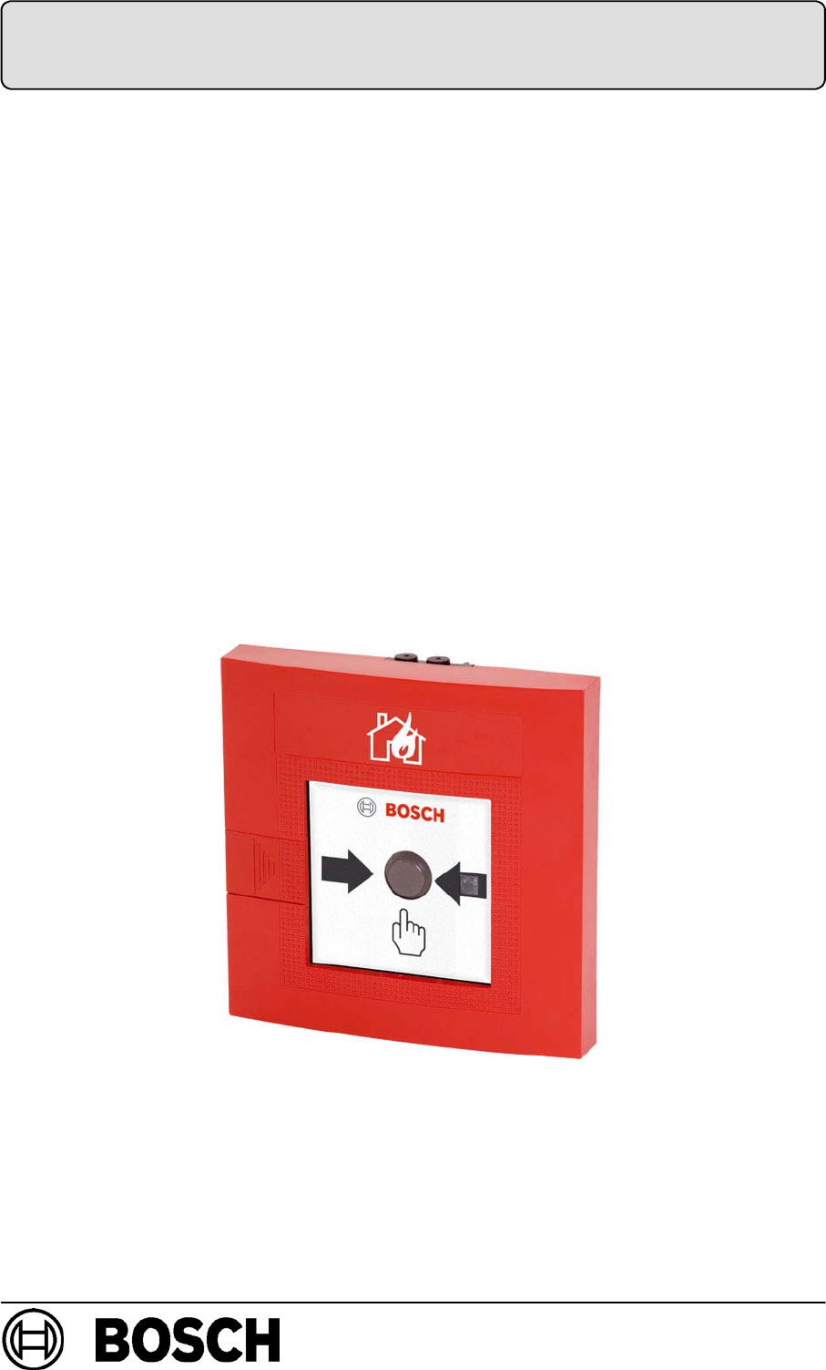
GLT - Non-Automatic Fire Detector Series 120
FMC-120-DKM-G-R / FMC-120-DKM-H-R
FMC-120-DKM-G-B / FMC-120-DKM-H-B /
FMC-120-DKM-G-Y
FMC-120-EST-G-B

Page 2 of 18
BDL-F.01U.066.178
A3.en/ 14.03.2008
ST-FIR/ PRM1 / sib

PI - 34.51 enProduktinformation FMC-120-DKM / EST GLT
Page 3 of 18
BDL-F.01U.066.178
A3.en/ 14.03.2008
ST-FIR/ PRM1 / sib
Table of contents
1. Product description 3...............................
2. Features 3.........................................
3. Planning notes 4....................................
3.1. Maximum number of detectors that may be connected 4......
3.2. Norms, guidelines and planning recommendations 4..........
3.3. Labelling variants 5..........................................
4. Order contents 6...................................
4.1. Basic model 6...............................................
4.2. Labelling foils 6.............................................
4.3. Accessories / Spare parts 6..................................
5. Device structure 7..................................
6. Functional description 8............................
6.1. Manual call point 8..........................................
6.2. Functional test 8............................................
6.3. Test detector 8..............................................
7. Installation 9.......................................
7.1. Installation dimensions (view: housing rear wall interior) 9....
7.2. Cable duct 9................................................
7.3. Installation variants for fire hose cabinets 10..................
7.4. Connection 11................................................
8. Notes on maintenance and service 12.................
8.1. Repair 12....................................................
8.2. Disposal 12..................................................
8.3. Additional documentation 12..................................
9. Technical specifications 13...........................
10. Table of abbreviations 14.............................
11. Notes 15............................................

PI - 34.51 enProduktinformation FMC-120-DKM / EST GLT
Page 4 of 18
BDL-F.01U.066.178
A3.en/ 14.03.2008
ST-FIR/ PRM1 / sib
1. Product description
The series 120 non-automatic fire detector is used for manual alarm triggering in conventional
line technology (GLT). The line is monitored according to the principle of voltage reduction and
increase.
The Form H detectors are designed for exterior areas, the Form G detectors for interior areas.
Overview of non-automatic fire detectors, series 120
Manual call points
DFMC-120-DKM-G-R Manual call point for interior areas (Form G), red
DFMC-120-DKM-H-R Manual call point for exterior areas (Form H), red
Manual call points
DFMC-120-DKM-G-B Manual call point for interior areas (Form G), blue
DFMC-120-DKM-H-B Manual call point for exterior areas (Form H), blue
DFMC-120-DKM-G-Y Manual call point for interior areas (Form G), yellow
Stop device
DFMC-120-EST-G-B Stop device for interior areas (Form G), blue
2. Features
DManual call point and stop device: Trigger alarm by pushing the button. After alarm
triggering, the push button is adjusted.
DDetector query routines with evaluation and multiple transmission.
DDisplay (LED) for triggered alarms or inspection evaluation.
DSecond contact with connections for panel control.
DSamedesignforinterioruse(FormG)andexterioruse(FormH).
DAvailable in different colour variants; see order overview.
DFor the red colour variants, a “burning house” is applied to the detector housing in the
factory.
DVariable labelling is possible with foil sets for the blue and yellow colour variants.
DFor exterior use in extreme environmental conditions, the detector is equipped with an
especially resistant PC board (parylene layering) and with a seal in the detector door.
PI - 34.51 enProduktinformation FMC-120-DKM / EST GLT
Page 5 of 18
BDL-F.01U.066.178
A3.en/ 14.03.2008
ST-FIR/ PRM1 / sib
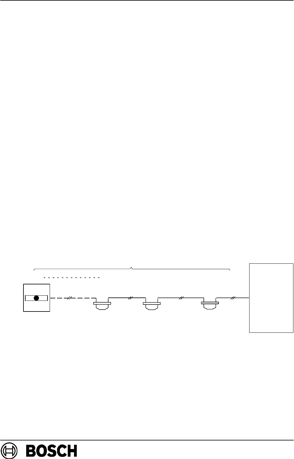
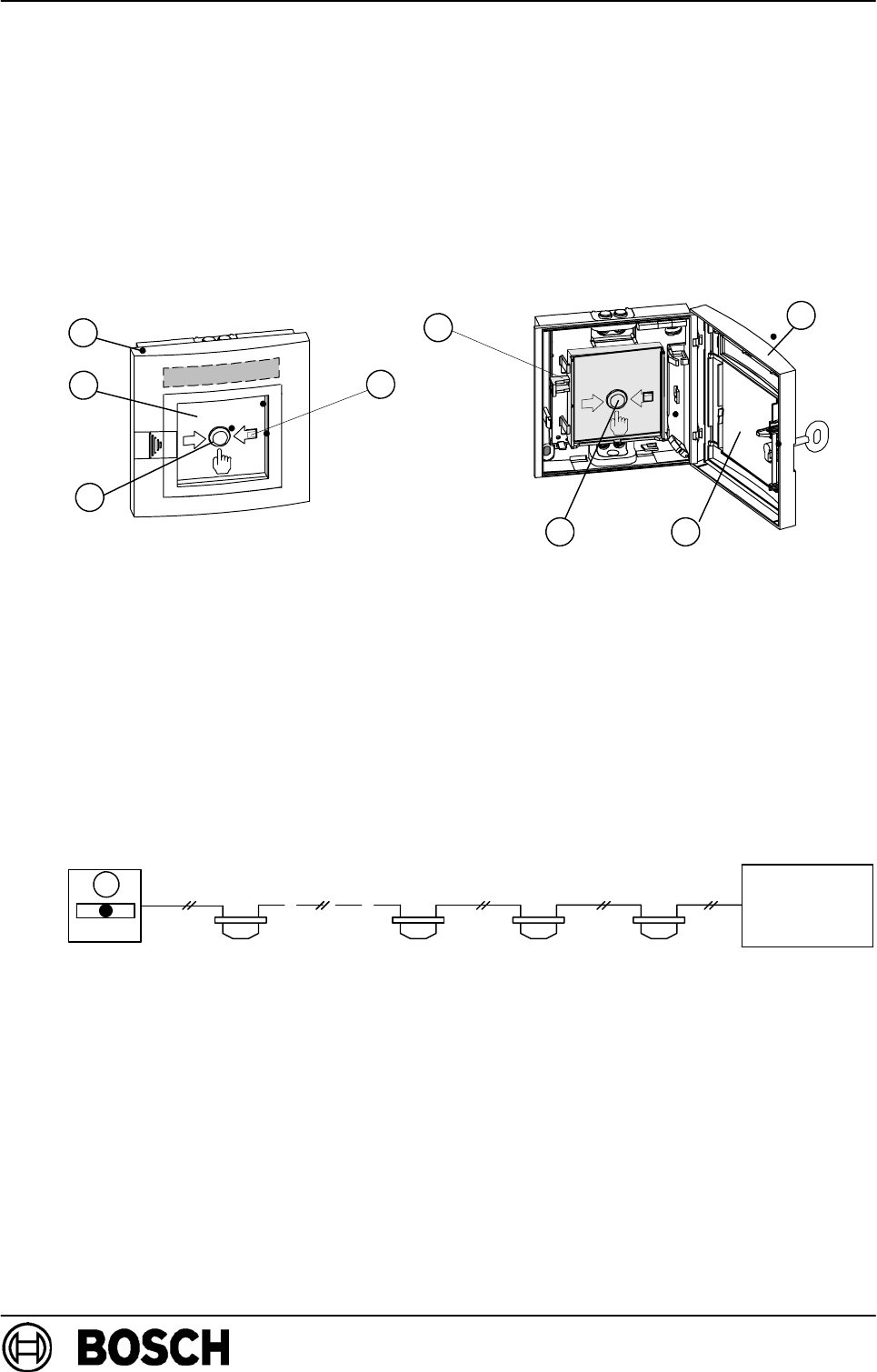
3. Planning notes
DNon-automatic fire detectors must be mounted visibly along escape and rescue routes
(e.g. exits, passageways, stairwells) and be easily accessible.
DAn installation height of 1400 mm (±200 mm), measured from the middle of the push
button to the floor, must be maintained.
DNon-automatic fire detectors must be sufficiently lit with sunlight or another light source
(including emergency lighting if present).
DThe distance between non-automatic fire detectors should not exceed 100 m according
to DIN 14 675 or 80 m according to VdS.
DIn high risk areas, non-automatic fire detectors should be installed at intervals of max. 40 m
(VDE 0833 Part 2, Point 7.2.6).
3.1. Maximum number of detectors that may be connected
In accordance with VdS guidelines, a maximum of 10 non-automatic fire detectors may be
connected to a primary line.
The test detector can be used for primary lines with automatic fire detectors. It is con-
nected to the electrical end of the primary line (max. 1 test detector per primary line).
3.2. Norms, guidelines and planning recommendations
Additional norms, guidelines, and planning recommendations with respect to installation loca-
tion etc. must be taken into account (see fire detector manual).
The regulations of the local fire services must be observed.
BMZ
Last detector Intermediate
2310
Fire detector
1
detector
Intermediate
detector
Intermediate
detector

PI - 34.51 enProduktinformation FMC-120-DKM / EST GLT
Page 6 of 18
BDL-F.01U.066.178
A3.en/ 14.03.2008
ST-FIR/ PRM1 / sib
3.3. Labelling variants
The detectors can be individually adapted to the location/application with optional label-
ling variants. This excludes detector variants FMC-120-DKM-G-R and
FMC-120-DKM-H-R, to which the “burning house” symbol has already been applied.
The self-adhesive labelling foils are stuck on the front panel of the detector.
PI - 34.51 enProduktinformation FMC-120-DKM / EST GLT
Page 7 of 18
BDL-F.01U.066.178
A3.en/ 14.03.2008
ST-FIR/ PRM1 / sib
4. Order contents
4.1. Basic model
Product ID DU* Designation
F01U011951 Pc FMC-120-DKM-G-R,
Manual call point for interior areas (Form G), red
F01U011952 Pc FMC-120-DKM-H-R,
Manual call point for exterior areas (Form H), red
F01U011953 Pc FMC-120-DKM-G-B,
Manual call point for interior areas (Form G), blue
F01U011954 Pc FMC-120-DKM-H-B,
Manual call point for exterior areas (Form H), blue
F01U011955 Pc FMC-120-DKM-G-Y,
Manual call point for interior areas (Form G), yellow
F01U012763 Pc FMC-120-EST-G-B,
Stop device for interior areas (Form G), blue
4.2. Labelling foils
Product ID DU* Designation
F.01U.012.951 PAK FMC-FST-DE,
Pre-cut and labelled foil sets for the top labelling field
(1 PACK = 5 sheets with 12 labelling variants)
F.01U.033.170 PAK FMX-FSO-GLT,
Pre-cut foil sets for the top labelling field (1 PAK = 10
sheets with 6 labelling variants). Appropriate for
printing at standard laser printers. The required print
file is available on the WinPara disk.
4.3. Accessories / Spare parts
Product ID DU* Designation
3.790.170.005 Pc “Out of order” - Metal stop sign
3.756.630.007 Pc Red plastic key (ASA) for detector door
F.01U.025.845 PAK FMC-SPGL-DEIL,
Replacement glass pane, dimensions 80 x 80 x 0.9 mm
(1 PACK = 5 pieces)
PI - 34.51 enProduktinformation FMC-120-DKM / EST GLT
Page 8 of 18
BDL-F.01U.066.178
A3.en/ 14.03.2008
ST-FIR/ PRM1 / sib
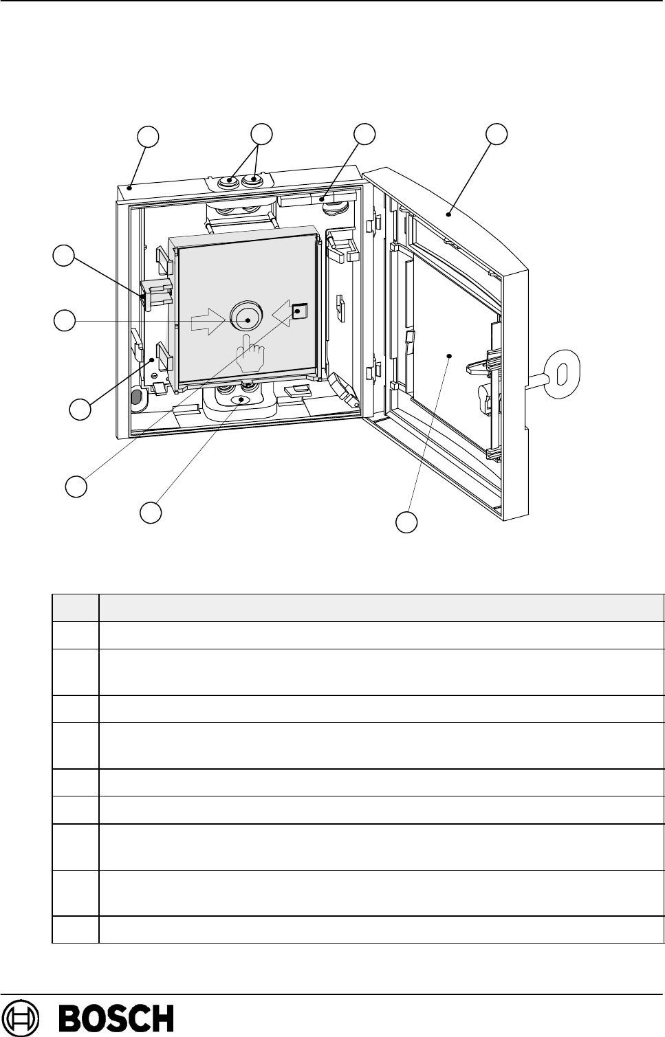
5. Device structure
The non-automatic fire detector is available in several variants and essentially consists of the
following elements.
1
7
5
2
34
8
2
6
9
Pos. Designation
1Plastic housing
2Cable ducts (interchangeable), for cable inlet and outlet.The cable
can also be ducted through openings in the rear wall of the housing.
3Connection terminal strip
4Detector door with replaceable glass pane, hidden lock
(and seal, for Form H)
5Glass pane
6Display (LED)
7PC board (with protective coating for Form H) The PC board is
clipped onto the floor of the housing.
8Trigger mechanism (clipped onto the PC board), consisting of plastic
frame and push button with spring.
9Reset lever (locking mechanism only for manual call points)
PI - 34.51 enProduktinformation FMC-120-DKM / EST GLT
Page 9 of 18
BDL-F.01U.066.178
A3.en/ 14.03.2008
ST-FIR/ PRM1 / sib
6. Functional description
6.1. Manual call point
Manual call point and stop device: In the event of an alarm, the glass pane (2) is broken
first, then the manual call point (3) is pressed hard.
This activates the microswitch for alarm triggering and the display LED (4) flashes.
A locking mechanism holds the pressed push button down.
The pressed push button is reset by manually activating the reset lever (5) or by opening
the detector door (1) ⇒ThealarmisresetandthedisplayLEDgoesout(4).
2
4
15
2
3
3
1
6.2. Functional test
Manual call point and stop device: To trigger the alarm, press the manual call point (3)
hard. The display LED (4) flashes. Use the reset lever (5) to return the manual call point to
the starting status.
6.3. Test detector
A maximum of 1 test detector (1) may be connected to the electrical end of the primary
line. Up to 30 automatic fire detectors may be connected to the primary line to be tested.
The test detector is supplied by the fire panel.
BMZ
12
max. 30
3
1
PI - 34.51 enProduktinformation FMC-120-DKM / EST GLT
Page 10 of 18
BDL-F.01U.066.178
A3.en/ 14.03.2008
ST-FIR/ PRM1 / sib
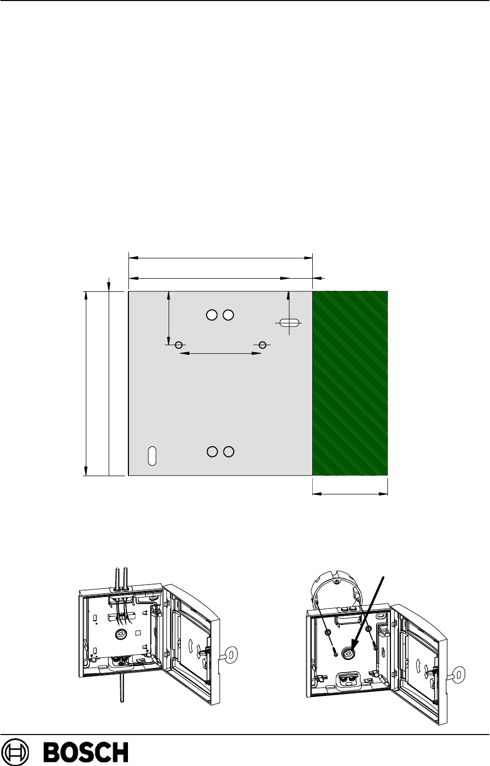
7. Installation
dThe non-automatic fire detector is designed for wall mounting.
dThe installation height, according to VdS regulations, is 1400 mm
(± 200 mm) from the floor to the centre of the push button.
dThe connection cables can be surface or flush-mounted.
The cable ducting should be carried out using the intended openings in
the housing (see 7.2 Cable duct).
dThe installation location is to be selected so that approximately 35 mm
space remains free on the right-hand side for opening the door.
7.1. Installation dimensions (view: housing rear wall interior)
60 mm
135 mm
37 mm
135 mm
17 mm
13 mm
approx. 35 mm
7.2. Cable duct
Surface-mounted cable duct Flush-mounted cable duct
via concealed box
PI - 34.51 enProduktinformation FMC-120-DKM / EST GLT
Page 11 of 18
BDL-F.01U.066.178
A3.en/ 14.03.2008
ST-FIR/ PRM1 / sib
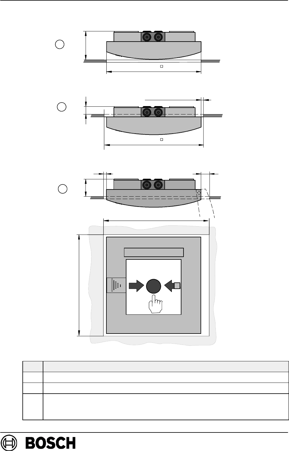
7.3. Installation variants for fire hose cabinets
135
140
2.5 mm
1
10
2
147
139
2
3
Pos. Description
1Installation depth version 1: min. 36 mm
2Installation depth version 2: 14 mm
3Installation depth version 3: approx. 30 mm
With this version, it is not necessary to open the door of the hose box e.g. for
maintenance.
PI - 34.51 enProduktinformation FMC-120-DKM / EST GLT
Page 12 of 18
BDL-F.01U.066.178
A3.en/ 14.03.2008
ST-FIR/ PRM1 / sib
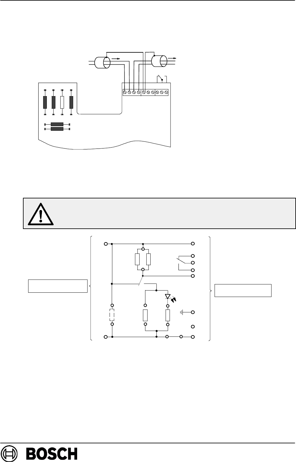
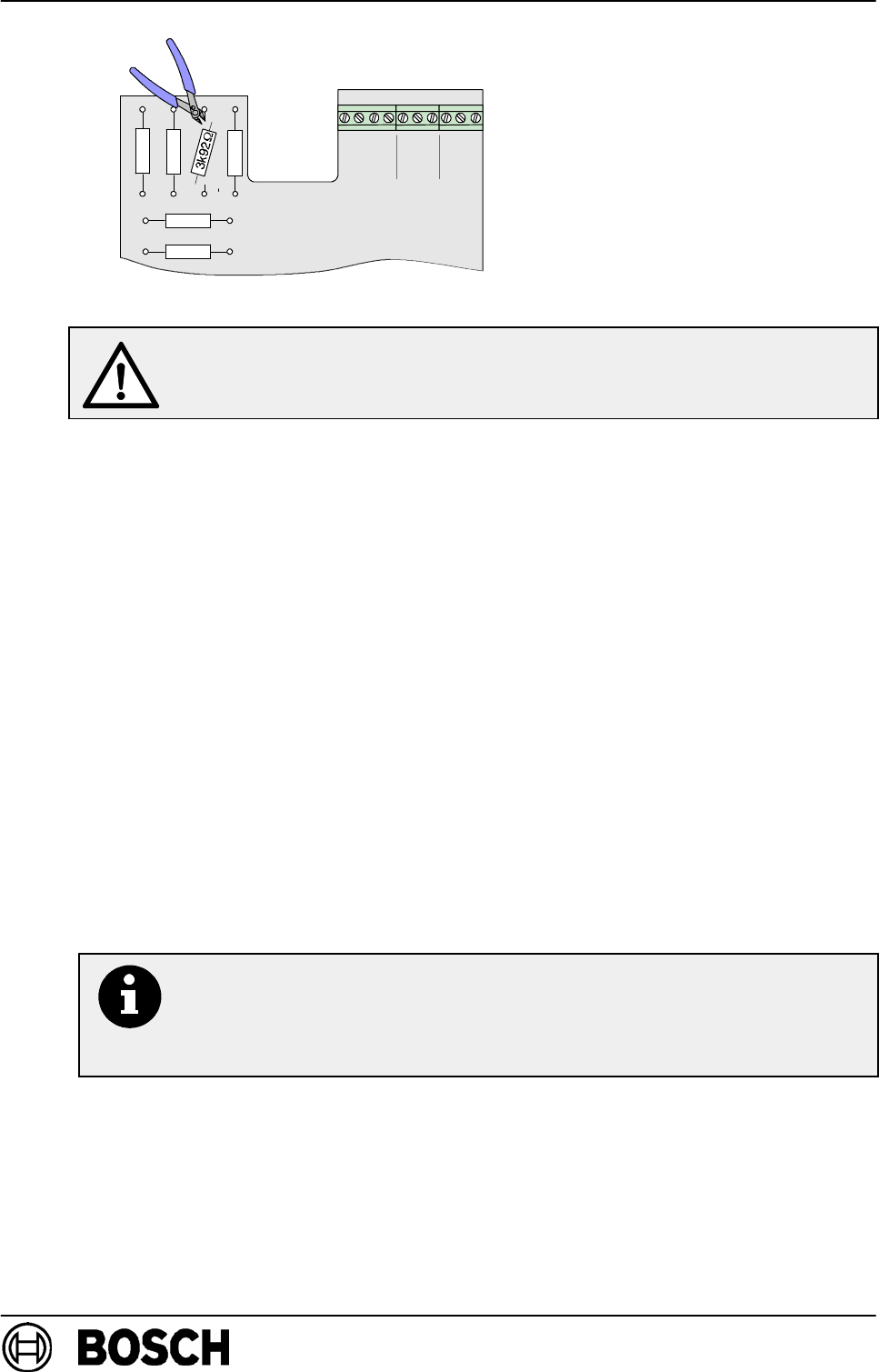
7.4. Connection
Detailed wiring diagrams and bridge assignments for connection to different fire panels are
showninthewiringdiagrammanual.
aba’
b’
1 2345678910
R4
R3
R5
R1
AB
EG
HK
J
C
D
F
R1 (A/B) = 820 ΩR3 (G/H)= 0 Ω
R4 (E/F) = 150 ΩR5 (J/K) = 0 Ω
R2
E
R6
R6 (A/B) = 2k21
+
-+
Endmelder / Last detector / Laatste melder:
R2 (C/D)= RE=3k92
-
In order to reach an alarm resistance of 820 Ohm in current gain operation,
resistor R6 must be removed. For other operating modes (voltage reduc-
tion), see the wiring diagram manual for the corresponding fire panel.
b’
3
2
A
B
JK
H
G
F
E
D
C
10
8
9
4
1
R4
R5
R2 R3
R1
a’
S1
S2
5
b
a
6
7
(E)
E
(RE)
To the next detector From the control panel
PI - 34.51 enProduktinformation FMC-120-DKM / EST GLT
Page 13 of 18
BDL-F.01U.066.178
A3.en/ 14.03.2008
ST-FIR/ PRM1 / sib
aba’b’
1
150W
2k21 W
0W
R3
R1
0W
R5
R4
R6
E
2345
T.1 T.2 T.3
678910
820W
Do not remove the end of line resistor from the last detector!
It must be removed from all other detectors.
8. Notes on maintenance and service
For maintenance and inspection work on security systems, the regulations of DIN VDE 0833
apply in Germany; these regulations refer to the maintenance intervals as per the manufac-
turer’s instructions.
DBosch ST recommends a functional and visual inspection at least once a year.
DMaintenance and inspection work should be carried out regularly and by trained personnel.
8.1. Repair
In the event of a defect, the entire unit is exchanged.
8.2. Disposal
Unusable units should be disposed of in accordance with regulations.
8.3. Additional documentation
For those with the appropriate access authorisation,
see Bosch ST ExtraNet at
www.boschbest.de
for the updated product information and the installation manual as a downloa-
dable PDF file.

PI - 34.51 enProduktinformation FMC-120-DKM / EST GLT
Page 14 of 18
BDL-F.01U.066.178
A3.en/ 14.03.2008
ST-FIR/ PRM1 / sib
9. Technical specifications
Technical specifications
Operating voltage 24 V DC (16.2 V DC to 30 V DC)
Current consumption specified by the respective security system
Protection category as per EN 60529
-FormH(exterior)
-FormG(interior)
IP 54
IP 52
Permissible ambient temperature
-FormH(exterior)
-FormG(interior)
-25_Cto +70_C/-13_Fto 158_F
-10_Cto +55_C/14_Fto 131_F
Standard (except FMC-120-DKM-G-Y) EN 54-11
Standard for FMC-120-DKM-G-Y EN 12094-3
Colours
RAL 5005 signal blue
RAL 1003 signal yellow
RAL 3001 signal red
Housing material Plastic, ASA (Acrylonitrile-Styrene-Acrylate Terpolymer)
Dimensions (W x H x D) 135 x 135 x 37 mm / 5.31 x 5.31 x 1.38 inches
Weight 224 g

PI - 34.51 enProduktinformation FMC-120-DKM / EST GLT
Page 15 of 18
BDL-F.01U.066.178
A3.en/ 14.03.2008
ST-FIR/ PRM1 / sib
10. Table of abbreviations
AHB = Wiring diagram manual
BMZ = Fire panel
BM = Fire detector
DIN = German Institute for Standardisation
DKM = Manual call point
EMZ = Intrusion control panel
EN = European standard
GMZ = Danger detection system
KI = Customer service information
LED = Light Emitting Diode
LSN = Local Security Network
SM = Single action call point
UGM = Universal danger detection system
VDE = Association of German Electrical Engineers
VdS = VdS Schadenverhütung GmbH

PI - 34.51 enProduktinformation FMC-120-DKM / EST GLT
Page 16 of 18
BDL-F.01U.066.178
A3.en/ 14.03.2008
ST-FIR/ PRM1 / sib
11. Notes
------------------------------------------------------------------
------------------------------------------------------------------
------------------------------------------------------------------
------------------------------------------------------------------
------------------------------------------------------------------
------------------------------------------------------------------
------------------------------------------------------------------
------------------------------------------------------------------
------------------------------------------------------------------
------------------------------------------------------------------
------------------------------------------------------------------
------------------------------------------------------------------
------------------------------------------------------------------
------------------------------------------------------------------
------------------------------------------------------------------
------------------------------------------------------------------

Page 18 of 18
Bosch Sicherheitssysteme GmbH
Robert-Koch-Straße 100
D-85521 Ottobrunn, Germany
www.bosch-sicherheitssysteme.de
info.service@de.bosch.com
