Bosch F01U087835 02 Easy Series 3 Ref Guide Quick Selection ( System Reference Guide) En US 2524758155
User Manual: Bosch Quick Selection Guide (- System Reference Guide) Easy Series Intrusion Control Panel
Open the PDF directly: View PDF ![]() .
.
Page Count: 126 [warning: Documents this large are best viewed by clicking the View PDF Link!]
Easy Series
ICP-EZM2
en System Reference Guide

Easy Series Table of Contents | en 3
Bosch Security Systems, Inc. System Reference Guide F01U087835 | 02 | 2008.10
Table of Contents
1Overview 6
1.1 Installation Workflow 6
1.2 System Components and Wiring 6
1.3 Phone Menus 10
1.3.1 Installer Phone Menu 10
1.3.2 User Phone Menu 11
2 System Installation and Configuration 12
2.1 Plan the Installation 12
2.2 Install System Components 13
2.2.1 Install the wLSN Hub 13
2.2.2 Install the Control Panel Enclosure 13
2.2.3 Install the Control Center 14
2.2.4 Route Power-limited Wiring 15
2.2.5 Install the ITS-DX4020-G Communicator and Antenna 15
2.2.6 Install the DX2010 Input Expander 16
2.2.7 Connect the Conettix DX4020 Network Interface Module 16
2.2.8 Connect Supervised Points 16
2.3 Apply System Power 17
2.4 Initial System Startup 18
2.5 Perform the RFSS Site Test using the wLSN Installation Tool 18
2.5.1 Prepare the wLSN Hub for Site Testing and RFSS Mode 19
2.5.2 wLSN Installation Tool Mode 1 19
2.5.3 wLSN Installation Tool Mode 2 20
2.5.4 wLSN Installation Tool Mode 3 21
2.6 Install wLSN Devices 22
2.7 Configure the System from the Installer Phone Menu 22
2.7.1 Upgrade the Control Panel (Optional) 22
2.7.2 Initiate a Phone Session from the Control Panel 22
2.7.3 Configure Required Control Panel Settings 22
2.7.4 Discover Wireless Devices 23
2.7.5 Add Users, Tokens, and Key Fobs 24
2.8 Configure the ITS-DX4020-G Communicator 25
2.8.1 Configure the Control Panel for Cellular Communication 25
2.8.2 Configure the ITS-DX4020-G 25
2.8.3 Test ITS-DX4020-G Communications 27
3 Point Expansion 28
3.1 Perform a RFSS Site Test with the Hub and the Device 28
3.2 Establishing the Wireless Network and Configuring Wireless Devices 28
3.2.1 Discover a New System 29
3.2.2 Establish and Configure the Wireless Network 29
3.2.3 Configure Devices 30
3.3 Wireless Maintenance 31
3.3.1 Wireless Configuration Menu 31
3.3.2 Assigning Points 1 to 8 as Wireless Points 32

4en | Table of Contents Easy Series
F01U087835 | 02 | 2008.10 System Reference Guide Bosch Security Systems, Inc.
3.3.3 Recovering the Wireless Network 32
3.3.4 Wireless System Messages 32
4 Programming Access Options 33
4.1 System Access by Phone 33
4.2 RPS 34
4.2.1 RPS Connection Methods 34
4.3 Programming Keys 36
5Programming 37
5.1 Basic Programming 38
5.1.1 Enter Basic Programming 38
5.1.2 Points 39
5.1.3 Report Configuration 40
5.1.4 Outputs 41
5.2 Expert Programming 42
5.2.1 ROM Firmware Version Items 43
5.2.2 System Programming Items 43
5.2.3 Communicator Programming Items 47
5.2.4 RPS Configuration Items 49
5.2.5 Route Reporting Options 50
5.2.6 Point Programming Items 52
5.2.7 Output Programming Items 54
5.2.8 Control Center Programming Items 55
5.2.9 User Programming Items 56
5.2.10 Factory Default 57
5.3 Exit Programming 57
6 Control Panel Event Codes (SIA and Contact ID) 58
7 Default the System 60
7.1 Default the Control Panel and the wLSN Hub 60
7.2 Default wLSN Devices 60
8 System Test and Maintenance 61
8.1 Test the System 61
8.2 Maintain the System 61
8.3 Installer History Event Announcements 61
8.4 Event Messages 61
9 ITS-DX4020-G Communicator Configuration 62
9.1 ITS-DX4020-G Communicator Overview 62
9.2 Short Message Service (SMS) Configuration 63
9.3 Accessing the User Interface and Logging On Using USB 65
9.3.1 Downloading the ITS-DX4020-G USB Driver 65
9.3.2 Installing the ITS-DX4020-G USB Driver 65
9.3.3 USB Main Menu 67

Easy Series Table of Contents | en 5
Bosch Security Systems, Inc. System Reference Guide F01U087835 | 02 | 2008.10
9.3.4 USB Option Menu 68
9.4 Upgrading the ITS-DX4020-G Software 70
9.4.1 Downloading the Latest Software 70
9.4.2 Installing the Software with Hyper Terminal 70
9.4.3 Installing the Software with Tera Term 71
10 Device Specifications and Overview 72
10.1 Control Panel 72
10.1.1 Standby Battery Calculation 74
10.2 Control Center 75
10.3 DX2010 Input Expander 78
10.4 Conettix DX4020 Network Interface Module 79
10.5 ITS-DX4020-G Communicator 79
10.6 wLSN Installation Tool 80
10.7 wLSN Hub 81
10.8 wLSN PIR and Dual Motion Detectors 82
10.9 wLSN Door-Window Contact 83
10.10 wLSN Recessed Door-Window Contact 83
10.11 wLSN Mini Door-Window Contact 84
10.12 wLSN Inertia Detector 85
10.13 wLSN Key Fob 87
10.14 wLSN Relay Module 89
10.15 wLSN Indoor Siren 90
10.16 wLSN Outdoor Siren 91
10.17 wLSN Smoke and Heat Detectors 92
10.18 wLSN Glassbreak Detector 95
10.19 wLSN Water Sensor/Low-temperature Sensor 100
11 Programming Details and Defaults 102
11.1 Programming Item Programming Details 102
11.2 Country Codes 107
11.3 Country Code Specific Default Programming Codes 108
12 Agency Approvals and Requirements 112
12.1 Certifications and Approvals 112
12.2 FCC 113
12.3 Industry Canada 114
12.4 SIA 114
12.5 Underwriters Laboratories (UL) 116
12.6 PD6662 and DD243 Requirements 118
12.7 EN50131 Requirements 119
12.8 INCERT 120
12.9 cUL 120
12.10 NF A2P 120
6en | Overview Easy Series
F01U087835 | 02 | 2008.10 System Reference Guide Bosch Security Systems, Inc.
1Overview
This document contains instructions for a trained installer to properly install, configure, and
operate the Easy Series control panel, and all optional peripheral devices.
You will install and configure the system using the figures starting in Section 1.2 System
Components and Wiring, page 6 and the information in Section 2 System Installation and
Configuration, page 12. The sections following Sections 1 and 2 provide supporting details for
installation, configuration, testing, and support.
1.1 Installation Workflow
To properly install, configure, and test the system, use the following workflow:
Table 1.1 Installation Workflow
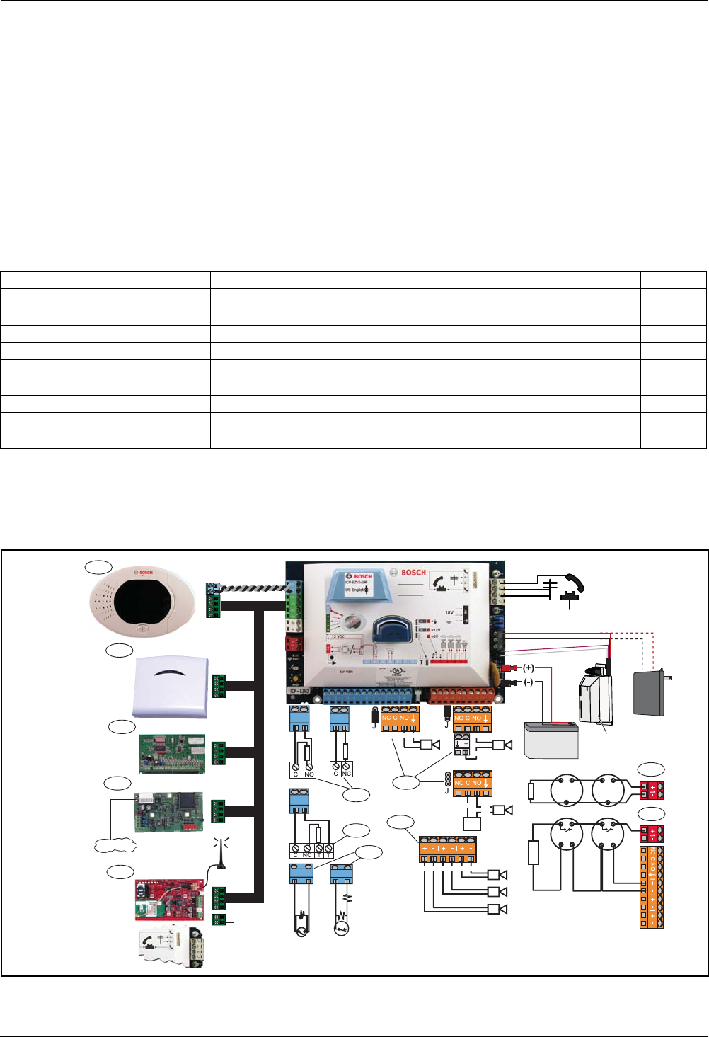
1.2 System Components and Wiring
Refer to Figure 1.1 through Figure 1.3 for overviews of the system components and wiring.
Figure 1.1 System Component Wiring Overview
Step Description Page
1. Plan the Installation Identify suitable locations for system component in the installation
site.
Page 12
2. Install the Hardware Install all system components. Page 13
3. Perform RFSS Site Test Perform radio frequency signal strength (RFSS) test. Page 18
4. Configure the System Enroll wireless devices into the system, perform basic programming
for the system, and add users to the system.
Page 22
5. Program the System Update the system with expert programming. Page 33
6. Test the System Perform a full system test. Ensure that the central monitoring station
received test reports.
Page 61
B
G
Y
R
+
-
IUI-EZ1
B
G
Y
R
ISW-BHB1-WX
B
G
Y
R
DX4020
B
G
Y
R
ITS-DX4020-G
B
G
Y
R
DX2010 (+) (-) (-)
(+)
(+) (-)(+) (-)(+) (-)
ICP-EZPS
1
4
2
5
11
3
12
6
7
8
9
10
T
T
(-)
(+) (-)
(+) (+)
Easy Series Overview | en 7
Bosch Security Systems, Inc. System Reference Guide F01U087835 | 02 | 2008.10
Callouts for Figure 1.2, Page 8
1Control Center Mount within 3 m of control panel, Use CAT5 cable (twisted pair) for audio
bus, Set data bus address (1 - 4), up to 4 controls max
2wLSN Hub S1 S2 S3
1 0 0 = Normal Operation
9 2 0 = RFSS Mode
9 8 7 = Default Hub (refer to Page 60)
DX2010 Point Expander Data Bus Adr 102: Points 9 - 16
Data Bus Adr 103: Points 17 - 24
Data Bus Adr 104: Points 25 - 32
4DX4020 Network Interface Module Data Bus Adr 134 1 - On
2 - Off
5ITS-DX4020-G Data Bus Adr 134 (Fixed)
6Supervised Points (single EOL) Normally open and normally closed options (2.2k Ω)
7Supervised Points (dual EOL) Normally closed (2.2k Ω)
8Keyswitch Options (single and dual EOL) ((2.2k Ω)
9Prog Output (PO) 1 Options Switched 12v Switched Ground Dry Contact
10 Prog Outputs 2 - 4 NF A2P requires that sirens have a backup battery. When this siren
requires a 14,1V to 14,4V supply, use the optional board EZPS-FRA or the
auxiliary power supply IPP-PSU-2A5. Set the output as interior burglary
alarm.
11 2-wire Smoke Detector Option EOL resistor (P/N: 25899) required.
12 4-wire Smoke Detector Option EOL resistor (P/N: 25899) and Bosch EOL relay module required
Note: The system uses a 12 VDC battery, connected as shown.
8en | Overview Easy Series
F01U087835 | 02 | 2008.10 System Reference Guide Bosch Security Systems, Inc.
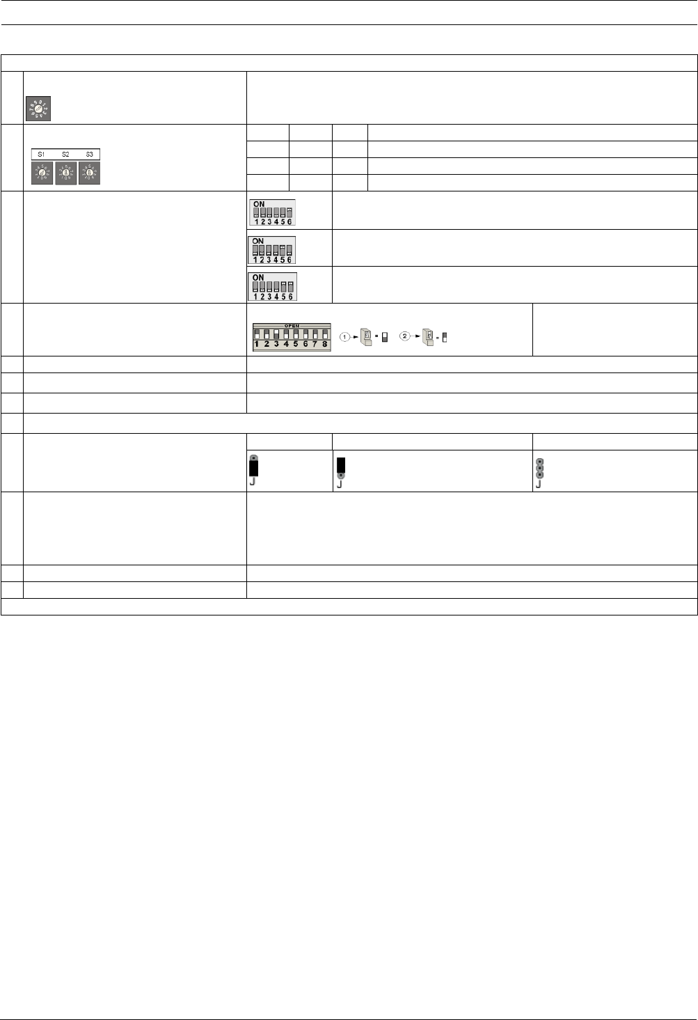
Figure 1.2 Overview of the System Component Location for the ICP-EZM2-R Enclosure
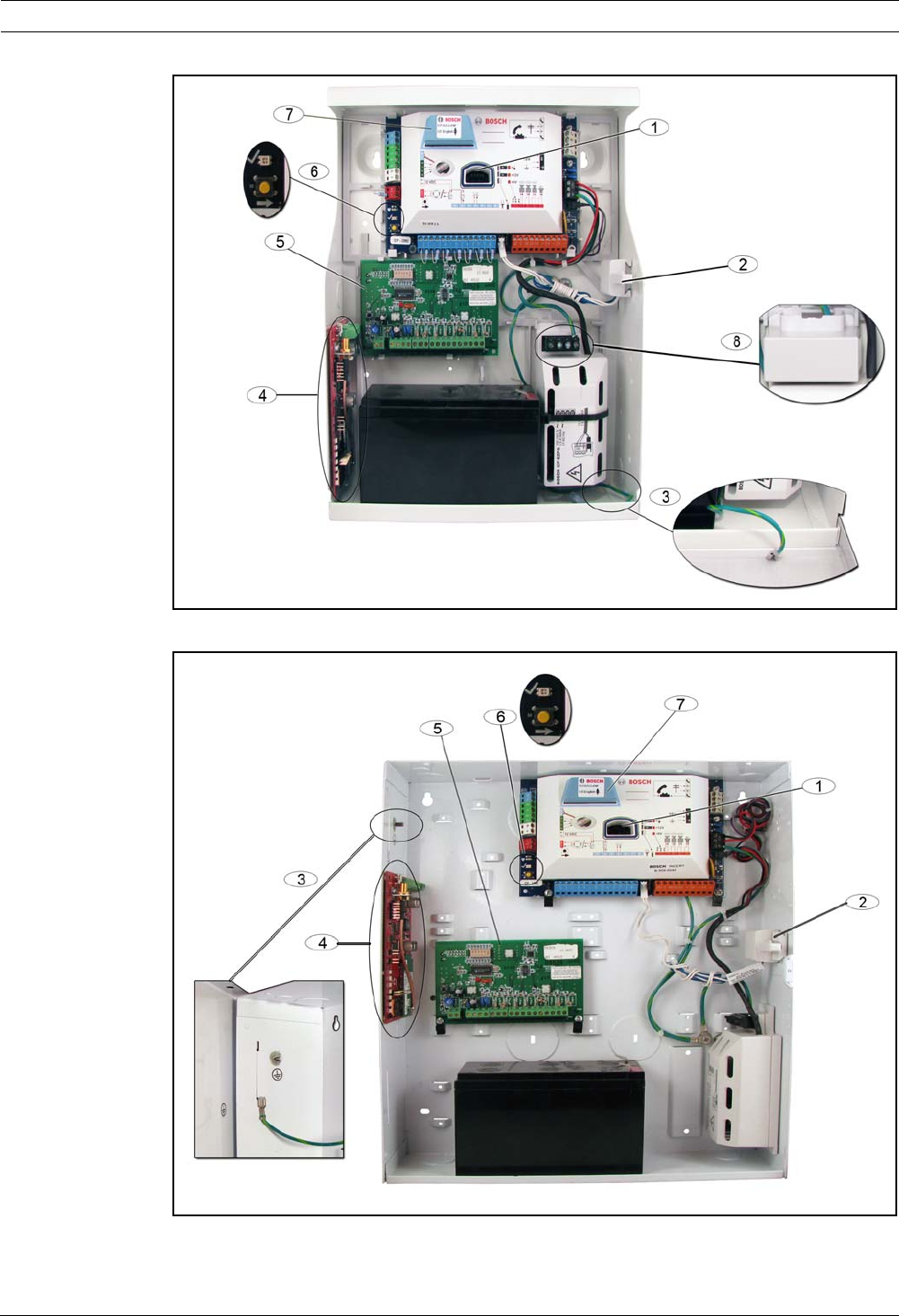
Figure 1.3 Overview of the System Component Location for the ICP-EZM2-EU Enclosure

Easy Series Overview | en 9
Bosch Security Systems, Inc. System Reference Guide F01U087835 | 02 | 2008.10
Callouts for Figure 1.2 Page 8 and Figure 1.3, Page 8
1Port for ICP-EZRU-V3 ROM Update Key and Programming Key
2Enclosure Cover and Wall Tamper Switch
3Ground connection
Connect ground wire from enclosure to enclosure door.
4Module mounting location
ITS-DX4020-G shown.
5Module mounting location
DX2010 shown.
6System test button
When the system is completely installed and programmed, press the system test button to start a full system
test.
7Port for ICP-EZVM voice module
8Enclosure terminal cover (ICP-EZM2-R Enclosure only)
Shipped in hardware bag. Install over terminals when power supply wiring is completed.
10 en | Overview Easy Series
F01U087835 | 02 | 2008.10 System Reference Guide Bosch Security Systems, Inc.
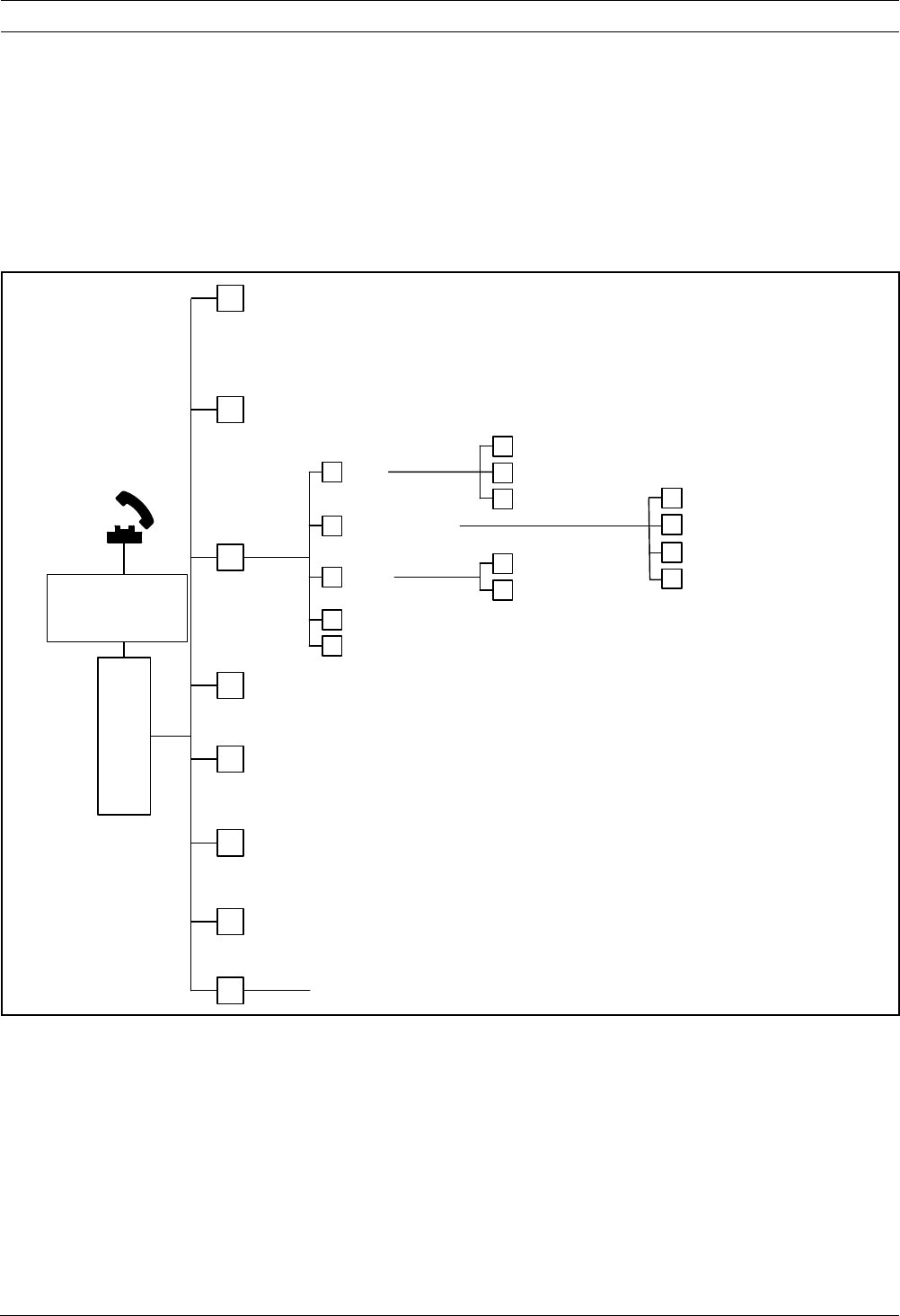
1.3 Phone Menus
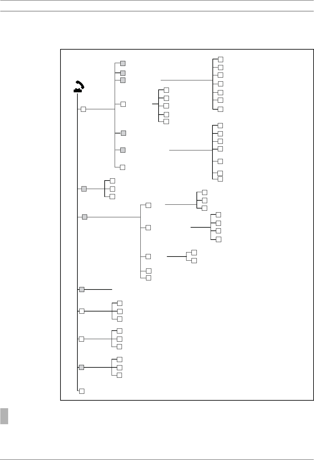
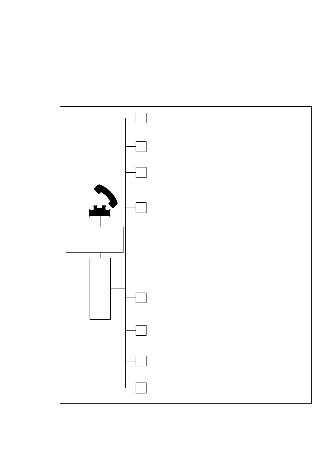
1.3.1 Installer Phone Menu
Basic
Programming
User Menu
System
Maintenance
Event history
System test menu
Set date and time
Full system test
Reset system
Exit
1
Wireless configuration
1
2
3
5
6
#
Exit
Warning device test
Battery test
Communication test
Control center test
Point test
Operate Outputs
2
3
4
5
6
#
1
Exit
Most recent events
Events by date
Last alarm event
Last 10 events
2
3
4
#
1
4
Exit
Replace a device
Add a device
Delete a device
Transfer wireless data
(control panel-to-hub)
Transfer wireless data
(hub-to-control panel)
Erase and discover
2
3
4
5
6
#
1
2
Change installer passcode
Change master user (User 1) passcode
Exit user menu
2
#
1
Installer
Passcode
3
Points
Report configuration
2
1
Record point description
Set point type
Exit
2
#
1
Enter account number
Configure report destinations
Remote programming success
Exit
2
3
#
1
Exit
Outputs
Country code
3
4
#
Select output function
Exit
#
1
Expert
Programming
4Enter programming item, enter selection.
Two-Way
Voice Session
5
Talk to person at control center
Listen to person at control center
Exit
2
#
1
Custom
Messages
6
Record site description
Record Call for Service message
Exit
2
#
1
Programming
Key
7
Send data from key to control panel
Send data from control panel to key
Exit
2
#
1
#Exit
= The system’s arming status (on or off) and Expert Programming Item Number 142 setting of (0 or 1) determines the availability of
these menu items. Refer to Section 5.2.2 System Programming Items, Page 43.
When recording any description (point, output, user, or custom message), do not press any buttons on your phone until
prompted by the system.
Easy Series Overview | en 11
Bosch Security Systems, Inc. System Reference Guide F01U087835 | 02 | 2008.10
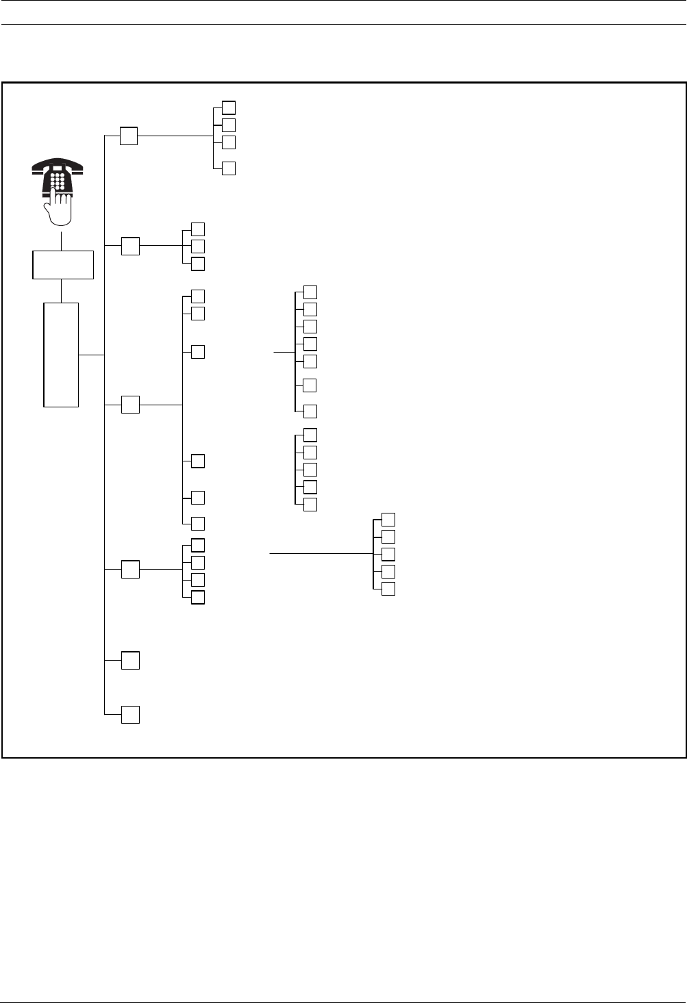
1.3.2 User Phone Menu
Exit system test menu
Two-Way
Voice Session
Talk to person at control center
Listen to person at control center
End voice session
1
2
#
Exit
1
2
#
Event history
System test menu
1Set date and time
Full system test
Reset system
2
3
Warning device test
Battery test
Communication test
Control center test
Point test
1
2
3
4
5
#
4
5
Exit
#
Most recent events
Events by date
Last alarm event
Last 10 events
Exit
1
2
3
4
#
System
Maintenance
2
3
Phone
Menu
Enter user
passcode
1
To hear this option, custom protection must be
enabled.
Only use this option
on non-UL systems.
Turn System On or Off
5
To turn an output on or off, press the
corresponding number key on the phone.
Operate Outputs
Turn system on and leave
Turn system on and stay inside
Turn on custom protection
1
2
3
#Exit
End phone session.
}The voice session only lasts 90 seconds.
To reset the timer, press [1] on the phone during talk mode,
or [2] during listen mode.
User Menu3
Add new user
Change user
Delete user
1
2
3
4
#Exit
To add or change a user:
}
Operate outputs
OR
Expert Programming (Enable Installer Access)
4
6
Only the Master User can
access the full User Menu.
Users 2 to 21 can only change
their own passcode.
Change token
Record description
Change passcode
Change key fob
Exit
1
2
3
4
#
1 Only a user passcode (Users 1 to 21) can access the User Menu.
2 If the system is on, the System Maintenance option is not available.
3 Only the master user can add, change, or delete users. Users 2 to 21 can only change their own passcodes. User voice descriptions are
stored in the voice module and are not transferred to the control panel with programming data.
4 Option 6 allows the master user (User 1) to enable the Installer Passcode. Refer to Expert Programming Item Number 142 in
Section 5.2.2 System Programming Items, Page 43.
Availability of the menu items shown above depends on the system's status.
When recording any description (point, output, user, or custom message), do not press any buttons on your phone until prompted
by the system.

12 en | System Installation and Configuration Easy Series
F01U087835 | 02 | 2008.10 System Reference Guide Bosch Security Systems, Inc.
2 System Installation and Configuration
2.1 Plan the Installation
When planning the installation, identify suitable locations for the control panel, control
center, hub, and wireless devices before installing any system components. When identifying
these locations, ensure that the following considerations are addressed.
Table 2.1 Installation Considerations
Task Considerations
1. Identify the location for
the control panel.
– Only use authorized service personnel to install this system.
– Plan to install the control panel in a centrally located room that is near the AC
Power MAINS.
– Plan to install the control panel in a location with a good earth ground.
– Because the control panel is permanently connected equipment, a readily
accessible disconnect device must be included into the building installation
wiring.
2. Test for GSM signal
strength.
Use your cell phone to identify an area with good GSM signal strength by monitoring
the signal strength on your mobile phone.
If the intended location of the control panel has poor GSM signal strength, find a
new location for the control panel.
3. Identify the location for
the control center.
Plan to install the control center near the primary entry and exit door.
4. Identify the location for
the wLSN Hub.
Plan to install the wLSN Hub in a location with good radio-frequency (RF)
characteristics and within 100 m of the control panel.
5. Identify the location for
the wLSN devices.
– wLSN devices are intended only for indoor, dry applications. Avoid installing the
devices where excessive humidity or moisture, or temperatures outside of the
acceptable operating range, exist.
– Mount wLSN devices on flat, rigid surfaces. For more information, refer to each
device's installation instructions.
– Avoid mounting wLSN devices in areas with large metallic objects, electrical
panels or electric motors. They might reduce the (RF) range of a wLSN device.

Easy Series System Installation and Configuration | en 13
Bosch Security Systems, Inc. System Reference Guide F01U087835 | 02 | 2008.10
2.2 Install System Components
2.2.1 Install the wLSN Hub
1. Separate the wLSN Hub from its base.
2. Set the wLSN Hub's rotary switches to enable RFSS mode: S1 = 9, S2 = 2, S3 = 0.
This is the setting required for the RFSS site test. Refer to Figure 1.1, Page 6.
3. Connect the wLSN Hub's data bus to the control panel's data bus. The wLSN Hub's
terminal block is removable.
–Wire Gauge: 0.14 mm to 1.5 mm (18 AWG to 24 AWG)
–Wire Length (sLSN Hub to control panel): <= 100 m
4. Reconnect the wLSN Hub and base, and then lock the wLSN Hub.
5. Mount the wLSN Hub temporarily in the desired location. You might need to relocate the
wLSN Hub if it does not pass RFSS testing.
2.2.2 Install the Control Panel Enclosure
1. Remove the desired knockouts from the control panel enclosure and optional mounting
skirt.
2. Attach the optional mounting skirt to the enclosure.
3. Route the wires through the desired knockouts.
4. Mount the enclosure to the desired surface. Use proper anchor and screw sets when you
install the enclosure on non-load-bearing surfaces, such as drywall.
i
NOTICE!
– Use proper anchor and screw sets when installing the enclosure on non-load-bearing
surfaces, such as drywall.
– Follow anti-static procedures when handling the control panel board. Touch the earth
ground terminal on the control panel board to discharge any static charge before working
on the control panel board.
– If you install more than one control center, mount them at least 1.2 m apart.
– Do not install the wLSN Hub within 15 cm (6 in) of the control centers metal enclosure.
i
NOTICE!
Refer to Figure 1.2, Page 8 or Figure 1.3, Page 8 throughout this section for the location to
install each of the hardware components in the enclosure.
14 en | System Installation and Configuration Easy Series
F01U087835 | 02 | 2008.10 System Reference Guide Bosch Security Systems, Inc.
2.2.3 Install the Control Center
1. Unlock the control center and separate it from the base.
2. If you install more than one control center, each control center must have a unique
address. Valid address are 1 to 4. Refer to Figure 2.1 for the location of the address
switch.
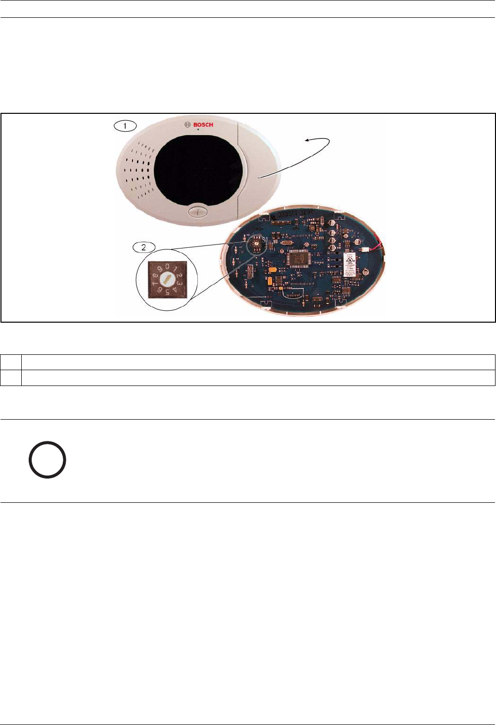
Figure 2.1 Control Center Address Switch
3. Mount the control center base to the desired surface using the appropriate mounting
holes. Use the built-in level in the control center base as a guide.
4. Connect the control center data bus terminals to the control panel data bus terminals.
Refer to Figure 1.1, Page 6.
5. Connect the control center audio bus terminals to the control panel audio bus terminals.
Twisted pair wiring is recommended for audio bus terminals. Refer to Figure 1.1, Page 6.
6. Reconnect the control center and base, and then lock the control center.
Refer to Section Control Center Display States, Page 75 for an overview of the various control
center display states.
1 Control Center’s front cover
2 Address switch’s default settings
i
NOTICE!
Mount the base to a non-metallic surface that is near the primary entry/exit door.
If you install more than one control center, ensure that there is at least 1.2 m between each
control center.
Avoid mounting the control center near existing phone lines.
Avoid mounting the control center near other electronic devices.
Easy Series System Installation and Configuration | en 15
Bosch Security Systems, Inc. System Reference Guide F01U087835 | 02 | 2008.10
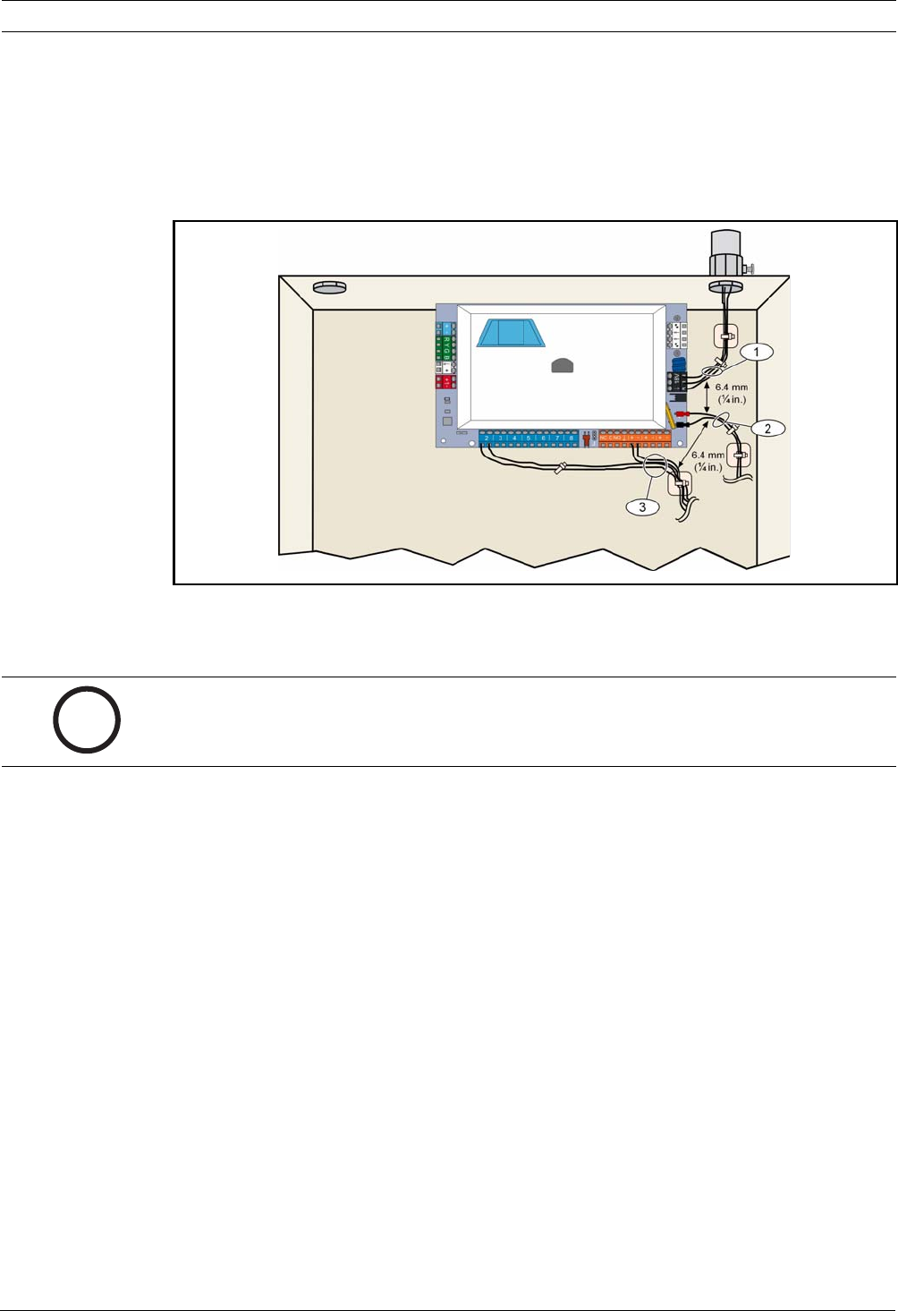
2.2.4 Route Power-limited Wiring
All wiring except primary AC power and standby battery is power-limited. Separate primary
AC power and standby battery wires from other wires by at least 6.4 mm (¼ in), and secure to
enclosure to prevent movement. Primary AC power and standby battery wiring cannot share
the same conduit, conduit fittings, or conduit knockouts with any other wiring. Refer to
Figure 2.2, Page 15.
Figure 2.2 Power-limited Wire Routing
2.2.5 Install the ITS-DX4020-G Communicator and Antenna
The ITS-DX4020-G is powered from the bus.
Refer to Figure 1.1, Page 6 for wiring instructions.
1. Install the ITS-DX4020-G SIM card.
a) Hold the ITS-DX4020-G communicator in the orientation shown in Figure 9.1, Page 62.
b) Slide the SIM cardholder door upward to unlock it, and then open the door.
c) Hold the SIM card in the orientation shown in Figure 9.1, Page 62, and then Insert the
SIM card into the cardholder door; the notched edge is away from the hinge.
d) Close the cardholder door, and then slide the door downward to lock it.
2. Mount the communicator into the control panel's enclosure using the side wall mounting
location.
3. Place the magnetic antenna on the panel enclosure (on top recommended for vertical
polarization). The antenna must be placed on a metal surface for proper operation.
4. Connect the antenna cable to the communicator.
5. Connect the audio terminals on the ITS-DX4020-G to the control panel’s inside phone
terminal block.
6. Connect the communicator option bus molex connector to the to the communicator and
connect the bus wires to the option bus terminals on the control panel. If preferred, the
terminal screws on the communicator can be used instead of the molex connection.
7. Install the configuration jumper on the CONFIG MODE (J200) pins. Refer to Figure 9.1,
Page 62 for the jumper location.
i
NOTICE!
When using the ITS-DX4020-G GSM channel for communications, do not permanently connect
a telephone to the Easy Series house phone terminals.

16 en | System Installation and Configuration Easy Series
F01U087835 | 02 | 2008.10 System Reference Guide Bosch Security Systems, Inc.
2.2.6 Install the DX2010 Input Expander
The control panel supports up to three DX2010 Input Expanders for Points 9 to 32.
Refer to the DX2010 Installation Instructions (P/N: 49533) for more information.
1. Set the DX2010's DIP switches.
2. Mount the DX2010 into the control panel's enclosure (back wall or either side wall), or
other suitable enclosure.
3. Connect the DX2010 to the control panel. Refer to Figure 1.1, Page 6.
Connect a wire jumper to the TMPR and COM terminals to disable the DX2010's tamper
input. For point wiring options, refer to Section 2.2.8 Connect Supervised Points, Page 16.
To disable the tamper input on the DX2010, connect a wire jumper between the TMPR
and COM terminals.
2.2.7 Connect the Conettix DX4020 Network Interface Module
The control panel supports one DX4020 for wired network communication.
Refer to the DX4020 Installation Instructions (P/N: F01U045288) for more information.
1. Set the DX4020's DIP switches to Address 134 for network communication.
2. Mount the DX4020 into the control panel's enclosure using the back wall or side wall
mounting location.
3. Connect the DX4020 to the control panel. Refer to Figure 1.1, Page 6.
2.2.8 Connect Supervised Points
For wiring diagrams, refer to Figure 1.1, Page 6.
Fire Point Wiring
Supervised Point 1 supports two- and four-wire smoke detectors.
Supervised Points 2 to 32 support only four-wire smoke detectors.
To program supervised points as fire points, refer to Section 5.1.2 Points, page 39.
For intrusion point configuration, refer to Section Intrusion Point Wiring, Page 16.
When using an output to supply power to a four-wire smoke detector, program the output
function for System Reset. Refer to Section 5.1.4 Outputs, page 41.
Intrusion Point Wiring
You can wire Supervised Points 1 to 32 as wired or wireless intrusion points.
To program Supervised Points 1 to 32 as intrusion points, refer to Section 5.1.2 Points,
page 39.
i
NOTICE!
In an NF A2P certified installation, mount the DX2010 module on one side of the panel
housing, or on one side of the auxiliary power supply IPP-PSU-2A5).
Easy Series System Installation and Configuration | en 17
Bosch Security Systems, Inc. System Reference Guide F01U087835 | 02 | 2008.10
2.3 Apply System Power
1. Connect battery power to the control panel. Refer to Figure 1.1, Page 6.
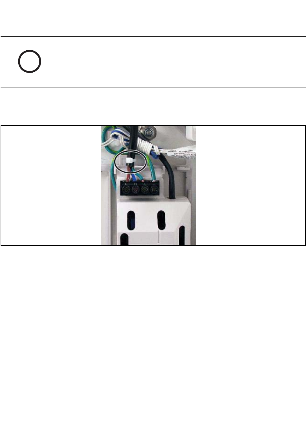
2. Use a cable tie to secure the incoming AC wires to the enclosure, where required. Refer
to Figure 2.3, Page 17.
Figure 2.3 Cable tie for MAINS to Power Supply
3. Place the terminal cover over the power supply terminals.
i
NOTICE!
Because the control panel is permanently connected equipment, a readily accessible
disconnect device must be included into the building installation wiring.
An external earth ground is required to ensure safe and proper system operation. Failure to
ground the system can cause personal injury and degraded system performance, such as
problems with tokens or noise on the control center.
18 en | System Installation and Configuration Easy Series
F01U087835 | 02 | 2008.10 System Reference Guide Bosch Security Systems, Inc.
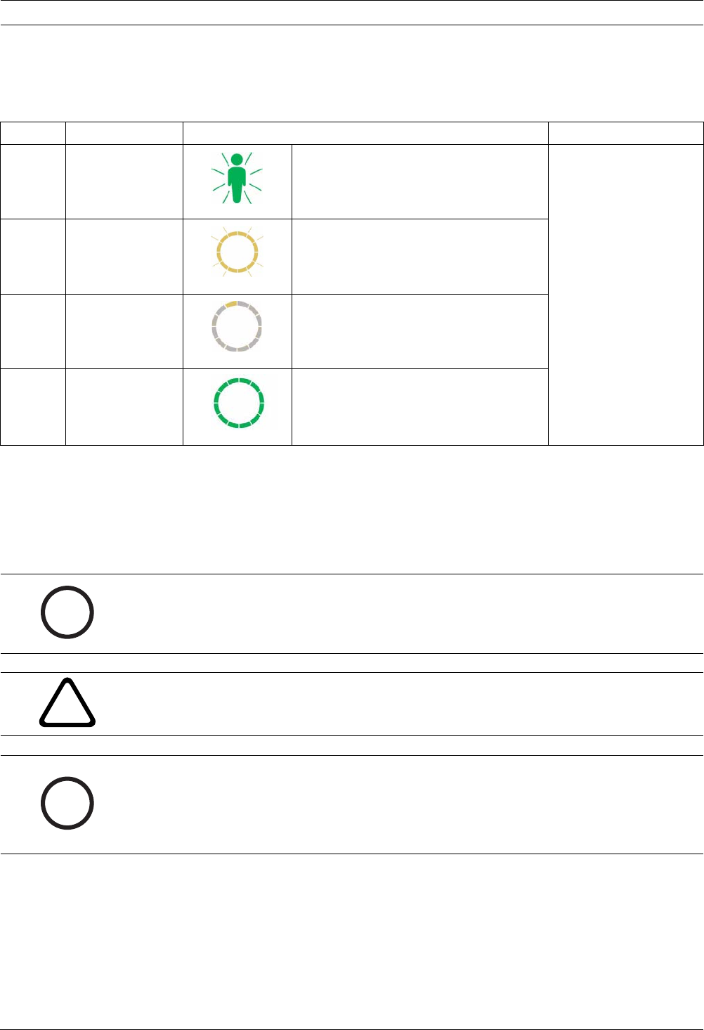
2.4 Initial System Startup
1. Apply AC power to the system.
2. Refer to Table 2.2 for the Initial System Startup sequence.
Table 2.2 Initial System Startup Sequence (No wLSN devices discovered)
2.5 Perform the RFSS Site Test using the wLSN Installation Tool
The wLSN Installation Tool communicates signal strength levels, noise levels, signal-to-noise
ratio (SNR), and packet success rates. Use it to determine the best locations for wLSN device
installation.
Stage Time Interval Control Center wLSN Hub
1 0-15 sec Intermittent flashing green icon LED on steady
2 15-45 sec Flashing amber circle
3 45-75 sec Single rotating amber segment
4 75 sec Solid green circle
i
NOTICE!
Before permanently installing any wLSN device, verify that the radio-frequency signal strength
(RFSS) between the planned device location and the planned wLSN Hub location is
acceptable.
!
CAUTION!
If you have wireless devices that you will not immediately install, reinsert the battery tabs or
remove the batteries to prevent battery depletion.
i
NOTICE!
You can perform the RFSS site test using the wLSN Hub and the specific device you wish to
test. However, you must use the Installation Tool with the wLSN Smoke Detector. You cannot
determine RFSS with the detector itself. Refer to Section 3.1 Perform a RFSS Site Test with the
Hub and the Device, page 28 for instructions.

Easy Series System Installation and Configuration | en 19
Bosch Security Systems, Inc. System Reference Guide F01U087835 | 02 | 2008.10
2.5.1 Prepare the wLSN Hub for Site Testing and RFSS Mode
1. Unlock the wLSN Hub and separate it from its base.
2. Set Switch S1 to 9 and Switch S2 to 2 to enable RFSS mode. This disables normal
operation. Refer to Figure 1.1, Page 6.
3. Set Switch S3 to a value of 0 to 4, based upon the RF power level or EN50131 security
grade you wish to use. Refer to Table 2.3.
Table 2.3 wLSN Hub RF Power/EN Settings
Refer to individual device's specification for their EN50131 classification.
4. Find a suitable location for the hub base and apply power by either connecting it to the
control panel (refer to the control panel's installation instructions), or temporarily
connecting a 9 VDC to 12 VDC battery.
5. Reconnect the wLSN Hub and base, and then lock the wLSN Hub.
2.5.2 wLSN Installation Tool Mode 1
Mode 1 identifies if a device location has acceptable or unacceptable RFSS.
To test the wireless devices with the Installation Tool in Mode 1:
1. Verify that the wLSN Hub rotary switch is set to S1 = 9, S2 = 2, S3 = 0. Refer to Figure 1.1,
Page 6. The wLSN Hub's LED flashes slowly.
2. Go to the first device location, and then press and hold [*][#] on the Installation Tool for
2 sec.
3. Press [1] for Mode 1.
4. Place the Installation Tool in an upright position at the first device location, or hold it in
the location, if necessary.
5. Wait 10 sec and then review the display.
– Acceptable RFSS Display:
– Unacceptable RFSS Display:
If the location tests:
–OK: Confirm that the location is OK by testing it with the actual wireless device for this
location.
–Not OK: Test a different location.
Switch 3 Setting RF Power (EN50131 Security Grade
0Maximum power
1 3 dB lower than maximum (Security Grade 1)
2 6 dB lower than maximum (Security Grade 2)
3 9 dB lower than maximum (Security Grade 3)
4 12 dB lower than maximum (Security Grade 4)
i
NOTICE!
You must test the devices at the same EN50131 Security Grade at which the control panel
discovers the devices.
MODE 1: +++OK+++
MODE 1 : - NOT OK -
20 en | System Installation and Configuration Easy Series
F01U087835 | 02 | 2008.10 System Reference Guide Bosch Security Systems, Inc.
2.5.3 wLSN Installation Tool Mode 2
To test the wireless devices with the Installation Tool in Mode 2:
1. Verify that the wLSN Hub rotary switch is set to S1 = 9, S2 = 2, S3 = 0. Refer to Figure 1.1,
Page 6. The wLSN Hub's LED flashes slowly.
2. Go to the first device location, and then press and hold [*][#] on the Installation Tool for
2 sec.
3. Press [2] for Mode 2.
4. Place the Installation Tool in an upright position at the first device location, or hold it in
the location, if necessary.
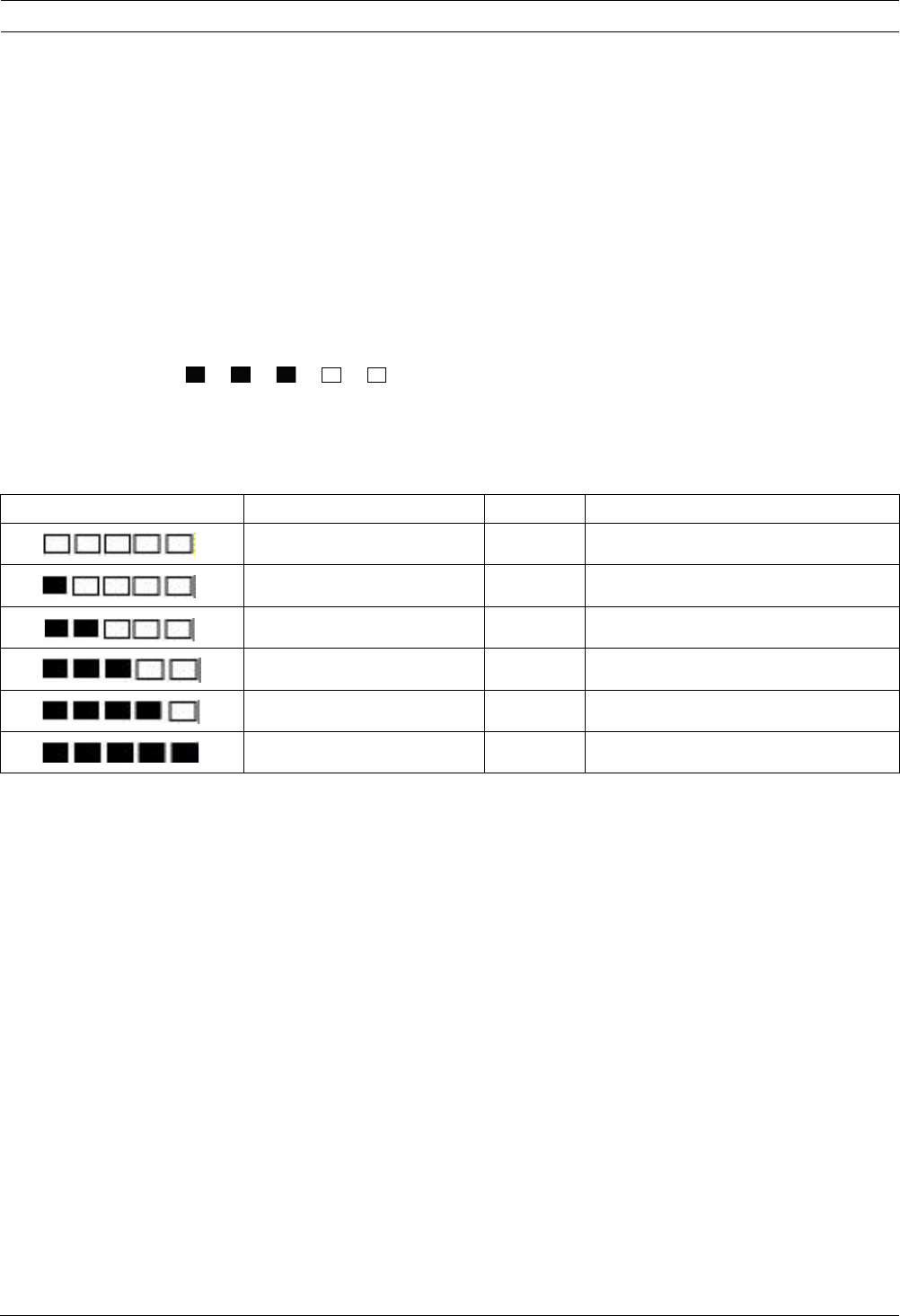
5. Wait 10 sec and then review the display.
The Mode 2 display shows power bars on the left and the number of packets received on the
right. The bars indicate the signal strength. The Installation Tool shows the number of packets
received: 1, 2, or 3.
Table 2.4 Mode 2 Display Data
If the location tests:
–OK: Confirm that the location is OK by testing it with the actual wireless device for this
location.
–Not OK: Test a different location.
MOD E 2 :
PACKETS=3
Power Bars Signal to Noise Ratio Packets Signal Strength
< 9 dB ≤2Unacceptable
9 dB ≥2Marginal (not recommended)
13 dB ≥2Acceptable
16 dB ≥2Good
20 dB ≥2Very good
22 dB ≥2Excellent

Easy Series System Installation and Configuration | en 21
Bosch Security Systems, Inc. System Reference Guide F01U087835 | 02 | 2008.10
2.5.4 wLSN Installation Tool Mode 3
When you perform the RFSS Site Test record the highest and lowest SNR readings because
you may need to compare them.
If the results for SNR fluctuate significantly, the location is:
–OK if you subtract the dB difference between the highest (H) result and the lowest (L)
result, and the number equals more than 13 dB. Confirm the location is OK by testing
with the actual wireless device for this location. (L - (H - L) ≥ 13 dB = OK
–Not OK if you subtract the dB difference between the highest (H) result and the lowest
(L) result and the number equals less than 13 dB. In this case, select a new location to
test. (L - (H - L) ≤ 13 dB = Not OK)
To test the wireless devices with the Installation Tool in Mode 3:
1. Verify that the wLSN Hub rotary switch is set to S1 = 9, S2 = 2, S3 = 0. Refer to Figure 1.1,
Page 6. The wLSN Hub's LED flashes slowly.
2. Go to the first device location, and then press and hold [*][#] on the Installation Tool for
2 sec.
3. Press [3] for Mode 3.
4. Place the Installation Tool in an upright position at the first device location, or hold it in
the location, if necessary.
5. Wait 10 sec and then review the display.
In the Mode 3 display, "SNR yy" refers to the signal to noise ratio in dB and "x" is the
RFSS value in dBm.
The Mode 3 display shows the signal to noise ratio (SNR) at the test spot. S refers to the
signal strength of the incoming message from the wLSN Hub to the Installation Tool. N
refers to the ambient noise level that exists at the location. The signal must be greater
than the noise (S>N). The higher the SNR, the stronger the location's signal at that
location. Dashes, appearing on both the S and N lines, indicate unacceptable signal
strength.
6. Note the readings for the location, especially the SNR values.
7. Refer to Table 2.5 to interpret the results based on the lowest and highest readings.
If one or more of the results for SNR falls below 13 dB, the location is Not OK.
Table 2.5 Signal to Noise Ratio Data
If the location tests:
–OK: Confirm that the location is OK by testing it with the actual wireless device for this
location.
–Not OK: Test a different location.
MODE 3: S- xxxdBm
SNRY N- xxxdBm
Signal to Noise Ratio Signal Strength
< 9 dB Unacceptable
9 dB Marginal (not recommended)
13 dB Acceptable
16 dB Good
20 dB Very good
22 dB Excellent

22 en | System Installation and Configuration Easy Series
F01U087835 | 02 | 2008.10 System Reference Guide Bosch Security Systems, Inc.
2.6 Install wLSN Devices
1. If RFSS is OK:
– Install the device's base and continue to the next location.
If RFSS is Not OK:
– Determine what is preventing acceptable RFSS and re-test.
– Move the device to a new location and re-test, or
– Move the wLSN Hub to a new location and re-test.
2. Repeat Steps 5 through 10 in Section 2.5 Perform the RFSS Site Test using the wLSN
Installation Tool on Page 18 until all locations are tested and all bases installed.
3. Press and hold [*][#] to exit from the test mode.
The Installation Tool powers down from the main menu 30 sec after the last key press.
4. Remove power from the system.
5. Set the wLSN Hub's rotary switches to: S1 = 1, S2 = 0, S3 = 0.
6. Reapply power to the system.
2.7 Configure the System from the Installer Phone Menu
2.7.1 Upgrade the Control Panel (Optional)
Insert the ICP-EZRU-V3 ROM update key.
The upgrade is complete (after 5 to 10 min), when the green (√) LED on the control panel
flashes. Remove the green upgrade programming key.
2.7.2 Initiate a Phone Session from the Control Panel
1. Connect a phone set to the test posts or to the phone terminals. Refer to Figure 1.1,
Page 6.
2. Press and hold the System Test button for approximately 15 sec. Figure 1.2, Page 8 for
the location of the Test button.
3. When prompted, use the phone set to enter the installer passcode (default is 5432[11])
for the Installer Menu, or the master user passcode (default is 1234[55]) for the User
Menu. For the following two procedures, enter the installer passcode.
2.7.3 Configure Required Control Panel Settings
1. From the Installer menu, if prompted to set the panel date and time, press [1][1]. When
finished following the prompts, press [#][#] to return to the Installer Menu.
2. If prompted to set the Country Code, press [3][4]. Refer to Section 11.2 Country Codes,
page 107 for the appropriate Country Code. When finished following the prompts, press
[#] to return to the Installer Menu.
i
NOTICE!
You can configure a control panel using pre-configured program data stored on a
programming key. For more information, refer to Section 4.3 Programming Keys, page 36.
i
NOTICE!
For more information on default passcodes, refer to Section 4.1 System Access by Phone,
page 33.

Easy Series System Installation and Configuration | en 23
Bosch Security Systems, Inc. System Reference Guide F01U087835 | 02 | 2008.10
2.7.4 Discover Wireless Devices
Discovery is the process through which the wLSN Hub identifies and includes new devices
into a system.
1. From the Installer Menu (refer to Section 2.7.2 Initiate a Phone Session from the Control
Panel, page 22), press [1][6] to start the Discovery Process.
2. Mask all motion detectors. (The optional ISW-BMASK-10 may be used.)
3. When the system announces, "Install all batteries," install the batteries or remove the
battery tabs from the wireless devices.
4. Press [1] to continue. The system then says, "Discovering devices, please wait."
During this time, the system finds all the undiscovered wireless devices. This process
takes approximately 6 min.
5. The system announces, "Wireless devices: xx. Test all points."
"xx" = the number of wireless devices discovered, but not yet tested.
6. Test each point. If specific point numbers are preferred, test points in the appropriate
order.
Refer to Table 2.6 for instructions on testing each wireless device.
i
NOTICE!
Point numbers are assigned to wireless devices in the order that the devices first
communicate to the system (tampered, faulted, low battery). If specific point numbers are
preferred for wireless devices, ensure that the wireless devices communicate in the
appropriate order. Otherwise, the system assigns the lowest available point number to the
first tested wireless device. With motion detectors, unmask only the detector you want to
test.
Device To Test
Motion Detectors Walk across the detector's coverage pattern.
Smoke Detector Press and release the detector's test button, or blow smoke into the detector's chamber
to cause an alarm. Restore the alarm.
Relay Module Input and Output: Fault and restore the supervised loop.
Output Only: Tamper the device.
Inertia Detector Magnetic Switch: Open and then close the switch.
Inertia Only: Cause an alarm and then restore the alarm1, or tamper the detector.3
Glass Break Detector Cause an alarm and then restore the alarm, or tamper the detector.3
Mini Door/Window
Contact
Recessed Door/Window
Contact
Open and then close the magnetic switch.
Door/Window Contact Open and then close the magnetic switch, or fault and then restore the supervised loop.
Perform both tests only if both the magnetic switch and supervised loop are used.
Indoor Siren Tamper the device.
Outdoor Siren Tamper the device. To configure the device, refer to Section 10.16 wLSN Outdoor Siren,
page 91.

24 en | System Installation and Configuration Easy Series
F01U087835 | 02 | 2008.10 System Reference Guide Bosch Security Systems, Inc.
Table 2.6 Wireless Device Test Procedures
After each successful point test, the system announces "Point xx was tested."
If you test a point and the system only announces "Point xx," the point number is assigned,
but has not been tested:
– If you prefer specific point numbers, do not continue. Fix any issue with the device and
re-test until the system announces "Point xx was tested."
– If you do not prefer specific point numbers, you can test them later through the Installer
Menu. When the system completes the testing, the system announces "Wireless devices
not configured."
7. The system says, "System test complete.”
2.7.5 Add Users, Tokens, and Key Fobs
1. From the User Phone Menu (refer to Section 2.7.2 Initiate a Phone Session from the Control
Panel, page 22), press [4] to enter the User Menu.
2. From the User Phone Menu, press [4] to enter the User Menu.
3. Press [1] to add a new user. After you add a new user, you can also assign a token,
passcode, and key fobs to that user.
4. Repeat Step 4 to add more users.
5. Press [#] to return to the User Menu.
Water Sensor/Low-
temperature Sensor
Water Sensor: Select one of the following methods:
– Short the water probe pins for at least 5 sec.
– Submerge the water probe in water for at least 5 sec.
Low-temperature Sensor: Short the "T" pads for at least 5 sec.
1 To test the inertia detector, create a shock to cause an inertia alarm, and then restore alarm.
2 To test the glass break detector, use a special tool to cause a glass break alarm, and then restore the alarm.
3 If you tamper the detector, the control panel enrolls the detector, but does not test it. You must create the appropriate alarm and
restore the alarm to test the detector.
Device To Test
i
NOTICE!
If you plan to use a programming key to copy control panel data for back up or use on another
system, back up the data now. Refer to Section 4.3 Programming Keys, page 36.

Easy Series System Installation and Configuration | en 25
Bosch Security Systems, Inc. System Reference Guide F01U087835 | 02 | 2008.10
2.8 Configure the ITS-DX4020-G Communicator
2.8.1 Configure the Control Panel for Cellular Communication
You must enabled GSM dialing, and set the format used and the destination IP address and
port number or phone number. You can also configure anti-replay and other parameters. To
do so:
1. Enable GSM dialing using Expert Programming Item 202.
2. For the primary and backup destinations, configure the control panel options as desired.
Refer to Table 2.7, Page 25 for an example of a typical configuration and the
corresponding Expert Programming Items.
Table 2.7 Example Configuration for Cellular Communications
2.8.2 Configure the ITS-DX4020-G
Ensure that the configuration jumper is installed on the CONFIG MODE (J200) pins.
Refer to Section 2.2.5 Install the ITS-DX4020-G Communicator and Antenna, page 15 for proper
installation.
1. Observe the LEDs to check for signal strength. Refer to Table 2.8, Page 25. Refer to
Figure 9.1, Page 62 for LED locations.
Table 2.8 ITS-DX4020-G Signal Strength LEDs
2. Call the central monitoring station (CMS) and provide the account number (may be
known as NNC number at the CMS), and control panel polling rate.
3. Observe the BUS LED. The LED stays on steady when the communicator has permission
to be configured. Refer to Figure 9.1, Page 62 for LED locations. Refer to row 2 in
Table 2.9, Page 26.
4. Observe the SS1 LED to confirm the ITS-DX4020-G is registered and has sufficient signal
strength to configure it by SMS. The SS1 LED must be On to continue. Refer to
Figure 9.1, Page 62 for LED locations. Refer to Table 2.8, Page 25 for the LED states.
5. Use the SMS configuration template to send the SMS to the installed SIM card phone
number. For detailed SMS configuration information, refer to Section 9.2 Short Message
Service (SMS) Configuration, page 63.
Format IP Address/Phone Number Port Anti-replay
Route 1 Primary (GPRS) Network 192.168.121.195 7700 1
Item Number to Configure 211 206 241 289
Route 1 Backup (GSM) Contact ID 1.585.223.4060 N/A N/A
Item Number to Configure 212 207
LED State
Strength/Comments STATUS CELL IP AUDIO SS1 SS2 SS3 BUS
Unacceptable—No reading available (modem is resetting or
registering).
⊗⊗⊗Off Off Off ⊗
Attempting to register on the GSM network. ⊗⊗⊗Flash Off Off ⊗
Unacceptable: < -89 dBm. ⊗⊗⊗On Off Off ⊗
Acceptable: -89 dBm to -83 dBm. ⊗⊗⊗On Flash Off ⊗
Good: -83 dBm to -77 dBm. ⊗⊗⊗On On Off ⊗
Very good: -77 dBm to -69 dBm. ⊗⊗⊗On On Flash ⊗
Excellent: > -69 dBm. ⊗⊗⊗On On On ⊗
Key: → = Scrolling LEDs, from left to right. ⊗ = LED’s status does not matter.
Shifting flash = Every other LED flashes simultaneously, creating the shifting flash pattern.

26 en | System Installation and Configuration Easy Series
F01U087835 | 02 | 2008.10 System Reference Guide Bosch Security Systems, Inc.
6. Observe the LEDs to confirm that the communicator received a valid configuration SMS.
Valid SMS configurationsshould be received within 5 min. Refer to row 4 in Table 2.9,
Page 26.
Table 2.9 Configuration Mode (J200 Jumper Installed) LED States
7. Remove the configuration jumper. The communicator reboots.
8. Ensure that the ITS-DX4020-G can communicate with the D6600/DX6600i. Refer to
Table 2.10, Page 26.
Table 2.10 D6600 Connection Status
LED State
State/Comments STATUS CELL IP AUDIO SS1 SS2 SS3 BUS
1No control panel authorization received. →→→GSM Signal Strength Off
2Installer is authorized for Configuration
mode, or authorization is not required.
→→→GSM Signal Strength On
3Received invalid SMS. →→→Flash Flash Flash Flash
4Received valid SMS authorizing
configuration.
→→→→→ → →
Key: → = Scrolling LEDs, from left to right. ⊗ = LED’s status does not matter.
Shifting flash = Every other LED flashes simultaneously, creating the shifting flash pattern.
i
NOTICE!
If the LEDs indicate an invalid SMS, remove the configuration jumper and then repeat the
steps in Section 2.8.2 Configure the ITS-DX4020-G, page 25.
If the LEDs continue to indicate an invalid SMS, the SMS template might be incorrect. Confirm
the SMS template format and settings and try again, or use a USB connection to configure the
ITS-DX4020-G.
CELL IP Status
Off ITS-DX4020-G is not connected to the GPRS network.
Flash ITS-DX4020-G is connected to the GPRS network, but not connected to the Bosch receiver.
On ITS-DX4020-G is connected to the Bosch receiver through the GPRS network.

Easy Series System Installation and Configuration | en 27
Bosch Security Systems, Inc. System Reference Guide F01U087835 | 02 | 2008.10
2.8.3 Test ITS-DX4020-G Communications
1. Configure the control panel for cellular communication, if necessary. Refer to
Section 2.8.1 Configure the Control Panel for Cellular Communication, page 25.
2. Send a test alarm using the GPRS network route, and then verify receipt of the alarm at
the CMS.
3. For systems using a ITS-DX4020-G with Network as the Primary Format (GPRS) and
Contact ID or SIA as the Backup Format (GSM), program and use a Manual Communicator
Test using Programming Item Number 362 (refer to Section System Report and Restoral
Routing, page 51). Then, send a test report using the PTSN using GSM destination and
observe the LEDs. Refer to Section 2.8.3 Test ITS-DX4020-G Communications, page 27 for
configuration information. To use the Manual Communicator Test:
a) Set the Format for Route 2 Primary Destination (Programming Item Number 213) the
same as the Format for Route 1 Backup Destination (Programming Item Number 212)
b) Set the Route 2 Primary Destination (Programming Item Number 208) the same as the
Route 1 Backup Destination (Programming Item Number 207).
c) Set Programming Item Number 362 to 2 (Route 2 only).
d) Set Programming Item Number 202 to 1.
4. If incoming GSM calling is enabled, initiate a phone call into the control panel voice
menu.

28 en | Point Expansion Easy Series
F01U087835 | 02 | 2008.10 System Reference Guide Bosch Security Systems, Inc.
3 Point Expansion
3.1 Perform a RFSS Site Test with the Hub and the Device
You can use the wLSN Hub and the wLSN device to perform an RFSS site test, or use the
wLSN Installation Tool (refer to Section 2.5 Perform the RFSS Site Test using the wLSN
Installation Tool, page 18).
1. Take the device being tested to its planned mounting location.
2. Remove and re-insert the device's batteries, then quickly press and release the tamper
switch button four times to enter RFSS mode.
3. Hold the device at the planned mounting location.
4. Determine if the RF signal strength is acceptable by observing the device's LED flash
pattern. The flash pattern appears for 10 min. Refer to Table 3.1, Page 28.
Table 3.1 wLSN Device LED Flash Patterns in RFSS Mode
3.2 Establishing the Wireless Network and Configuring Wireless
Devices
In order for the wireless network to operate properly, the following process must occur as
shown below.
LED Flash Pattern
Flashes at 1 sec intervals No packets received or unacceptable signal strength condition.
Flashes rapidly (0.2 sec intervals) Acceptable signal strength.
i
NOTICE!
To cause a device to exit RFSS mode, remove the device's batteries and re-insert them.
Devices automatically exit RFSS mode after 10 min of inactivity.
→Inputs and
Outputs
Discover
Devices
→Establish
Network
→Configure
Network
→Configure
Devices
→Key Fobs

Easy Series Point Expansion | en 29
Bosch Security Systems, Inc. System Reference Guide F01U087835 | 02 | 2008.10
3.2.1 Discover a New System
Discovery is the process through which the wireless hub identifies and includes new
(undiscovered) devices into the system.
There are two ways to start the discovery process on a new system: point test, and the
Wireless Configuration Menu: Point Test and the Wireless Configuration Menu.
Point Test
The device discovery process automatically starts at the beginning of the Point Test.
To start a point test from the System Test Button:
1. Ensure that all devices have exited RFSS Mode, including the wLSN Hub.
Ensure the wLSN Hub is in normal operating mode (LED is on steady).
2. Press the System Test button for one second.
To start a point test from the Phone Menu:
From the Installer Menu of a phone session (refer to Section 2.7.2 Initiate a Phone Session from
the Control Panel, Page 22):
– Press [1], and then press [2] to select Full System Test.
OR
– Press [1], and then press [3] to select System Test Menu. From the System Test Menu,
press [5] to select Point Test.
Wireless Configuration Menu
1. Enter the Installer Menu of a phone session (refer to Section 2.7.2 Initiate a Phone Session
from the Control Panel, Page 22).
2. Press [1][6] to select System Maintenance Wireless Configuration. The device discovery
process automatically starts.
3.2.2 Establish and Configure the Wireless Network
The wLSN Hub automatically establishes and configures the wireless network.
The wLSN Hub evaluates each available radio frequency (RF) for noise, RF signal strength, and
other adjacent wireless systems. The wLSN Hub then selects the frequency with the lowest
amount of noise and least amount of traffic for network operation.
To configure the wireless network, the wLSN Hub selects the best channel for broadcasting.
Once a channel is selected, the wLSN Hub then configures all discovered devices to operate
on the selected frequency. This process takes several minutes.
i
NOTICE!
You can only perform the new system discovery process once. To update an existing wireless
system, refer to Section 3.3 Wireless Maintenance, Page 31.

30 en | Point Expansion Easy Series
F01U087835 | 02 | 2008.10 System Reference Guide Bosch Security Systems, Inc.
3.2.3 Configure Devices
Input and Output Devices
Once the network is established and configured, the system announces "Test all points." Test
the wireless devices in this order: input devices, output devices, and relay modules.
When you restore the device, the system announces the assigned device number.
Test Devices
Point numbers are assigned to wireless devices in the order that the devices first
communicate to the system (tampered, faulted, low battery). If specific point numbers are
preferred for wireless devices, ensure that the wireless devices communicate in the
appropriate order. Otherwise, the system assigns the lowest available point number to the
first tested wireless device. With motion detectors, unmask only the detector you want to
test. Refer to Table 2.6 on Page 24 for wLSN device testing instructions.
Key Fobs
1. After the last wireless device is configured and the Point Test ends, press [#] repeatedly
until you exit the Installer Menu and end the phone session.
2. Start a new phone session, or press and hold [3] on the control center, and enter the
master user (User 1) passcode.
3. Press [4] [1].
4. Enter a passcode, and then re-enter the passcode.
5. Press [4] to add a key fob. Token assignment and voice description are optional.
6. Repeat Steps 4 to 7 to add more users and key fobs, or press [#] repeatedly to end the
phone session.
To create a key fob-only system (no wireless input or output devices installed), start at Step 2.
In a key fob-only system, adding the first key fob might take several minutes to complete as
the wireless network is established and configured. Subsequent key fob additions take less
time.
i
NOTICE!
The ISW-BMC1-S135X Door/Window Contact and the ISW-BIN1-S135X Inertia Detector have a
magnetic switch as an input. If the magnetic switch is not used, remove the magnet from the
device before starting the Point Test.
i
NOTICE!
Do not exit the Point Test until all intended wireless devices are tested. Otherwise, you must
manually add devices to the system.
If extra wireless devices not intended for installation are within the wireless hub's range, the
wLSN Hub might also discover these devices. To exclude any unused devices from the system,
press [#] (or [5] from the control center) to exit the Point Test. The wLSN Hub returns all
unused devices to the undiscovered state.

Easy Series Point Expansion | en 31
Bosch Security Systems, Inc. System Reference Guide F01U087835 | 02 | 2008.10
3.3 Wireless Maintenance
3.3.1 Wireless Configuration Menu
Use the Wireless Configuration Menu to:
– Add new wireless devices to an existing wireless system
– Add wireless devices that were not discovered when the wireless network was first
discovered
– Replace or delete wireless devices from an existing wireless system
To access the Wireless Configuration menu from the Installer Menu of a phone session (refer
to Section 2.7.2 Initiate a Phone Session from the Control Panel, Page 22), press [1] [6] for
Wireless Configuration.
Menu options are only available after the initial device discovery and point test is completed.
Button
Press
Menu Option Description
[1] Replace a Device Use this option to replace a known device with a new device.
– Press [1] to replace a point, or [3] to replace an output.
For a relay module, select either the input or output, and then enter the
appropriate number in Step 2.
– Enter the desired point number or output number.
The device discovery process starts.
– When the system announces "Test all points," activate the new device.
The new device replaces the current device. If other devices were
discovered in Step 2, they are returned to the undiscovered state.
[2] Add a Device Use this option to add more devices to the wireless network.
When you press [2] to select this option, the device discovery process starts.
When the system announces "Test all points," activate all of the new devices.
If other devices were discovered but not activated, they are returned to the
undiscovered state.
[3] Delete a Device Use this option to delete a known device from the system:
– Press [1] to delete a point, or [3] to delete an output.
– Enter the desired point number or output number.
If the selected point number corresponds with a relay module, both the
input and output are deleted from the system. If you only want to delete the
input or the output, you must disable the corresponding function through
programming.
– Press [1] to delete the device.
The wireless hub deletes the device from the system, and the point type or
output function is set to 0 (Disabled).
[4] Transfer Wireless Data
(control panel-to-hub)
If you replace a hub, select this option to send wireless data from the control
panel to the wireless hub.
[5] Transfer Wireless Data
(hub-to-control panel)
If you replace the control panel, select this option to send wireless data from
the wireless hub to the control panel. This option deletes key fobs.

32 en | Point Expansion Easy Series
F01U087835 | 02 | 2008.10 System Reference Guide Bosch Security Systems, Inc.
Table 3.2 Wireless Configuration Menu Options
3.3.2 Assigning Points 1 to 8 as Wireless Points
To assign an on-board point (1 to 8) as a wireless point, disable the point in programming
before starting the device discovery process. You can individually assign Points 1 to 8 as
wireless points.
3.3.3 Recovering the Wireless Network
Expert Programming Item Number 9999 restores the control panel to its factory default
settings. All wireless network data in the control panel is lost, but is retained in the wireless
hub.
To recover wireless network data from the wireless hub:
1. From the Installer Menu of a phone session (refer to Section 2.7.2 Initiate a Phone Session
from the Control Panel, Page 22), press [1] to select System Maintenance.
2. Press [6][5] to transfer wireless data from the hub to the control panel.
This option deletes key fob assignments. You must reassign all key fobs.
3.3.4 Wireless System Messages
Refer to the following table for a description of system messages that pertain to the wireless
network.
Table 3.3 Wireless System Messages
[6] Erase and Discover If the wireless data in the control panel does not match the wireless data in the
hub (Bus Device Trouble 50), use this option to erase the wireless data in both
the control panel and hub, and rediscover all devices.
This option is only available if the wireless data does not match in the control
panel and hub.
[#] Exit Wireless
Configuration
Select this option to return to the System Maintenance options.
Button
Press
Menu Option Description
System Message Description
“Wireless devices not configured.” Point Test was exited before all wireless points were tested.
“Extra device ignored.” An attempt was made to add a device to a system that already contains the
maximum number of points or outputs.
“Point x was tested.” A point was tested. RFSS is acceptable.
“Point x low.” A point was tested. RFSS is unacceptable.
“Please wait.” The wireless network is busy, or the control panel is waiting for the wireless
network to respond. The control center might show a single rotating segment
of the circle of protection with this message.
“Wireless error.” The wireless hub is jammed, missing, or experiencing a trouble condition.
“Wireless devices x.” “x” = the number of devices that are discovered, but not tested.
“Wireless devices not tested x.” “x” = the number of devices that are discovered, but not yet configured.
“Point x not tested.” The control panel assigned a point number to the device, but the device was
not tested (faulted, or tampered, and restored).
“x” = the voice description.
By default, the system announces the point number.

Easy Series Programming Access Options | en 33
Bosch Security Systems, Inc. System Reference Guide F01U087835 | 02 | 2008.10
4 Programming Access Options
You can access the system to make programming changes using:
– The Phone Menu
– Remote Programming Software (RPS)
– A Programming Key (using programming copied from a control panel previously
programmed using the Phone Menu or RPS)
4.1 System Access by Phone
The Installer Phone Menu and User Phone Menu provide access to system functions such as
testing the system, programming the system, and adding or changing users.
The Installer Phone Menu requires the installer passcode.
The User Phone Menu requires either the master user (User 1) passcode for full menu access,
or a user passcode for limited menu access.
If the passcode length = four digits:
– The default installer passcode is 5432
– The default master user passcode is 1234
If the passcode length = six digits:
– The default installer passcode is 543211
– The default master user passcode is 123455
To access the system menus, select one of the options shown in Table 4.1, Page 33.
Table 4.1 Phone System Access Options
i
NOTICE!
Once you configure a control panel using the Phone Menus, you can copy the programming
from the control panel to a programming key for use on another control panel, or for backup.
Refer to Section 4.3 Programming Keys, page 36.
Options Steps
House Phone – Press [#][#][#].
– Listen for the voice prompt to enter a passcode.
– Enter the installer passcode to access the installer menu, or a user passcode to access
the user menu.
Outside Phones – Call the premises phone number.
– After the call is answered by a person or by a telephone answering device, press
[*][*][*] to disconnect the answering party and access the system.
– Listen for the voice prompt to enter a passcode.
If the phone is not answered by a person or telephone answering device, the system
answers after a programmed number of rings. Refer to Expert Programming Item
Number 222 listed in on Section Route Destination Items, page 47.
– Enter the installer passcode to access the installer menu, or a user passcode to access
the user menu.
Installer Quick
Connect
Select this option if a phone line is not available, or a local connection is required. The
system must be off to use this option.
– Connect a phone set to the test posts or to the phone terminals.
– Press and hold the System Test button for approximately 15 sec.
– Listen for the voice prompt to enter a passcode.
– Enter the installer passcode to access the Installer Menu, or a user passcode to access
the User Menu.

34 en | Programming Access Options Easy Series
F01U087835 | 02 | 2008.10 System Reference Guide Bosch Security Systems, Inc.
4.2 RPS
RPS (Remote Programming Software) is a Windows-based account management and control
panel programming utility designed to remotely set up and program specific control panels.
You can use RPS to program the control panel from a laptop or PC that is on-site or off-site
from the control panel.
For complete installation and operation instructions, refer to the RPS Installation and
Operation Guide (P/N: 4998141259) that is available on the RPS CD-ROM.
4.2.1 RPS Connection Methods
You connect to the Easy Series Control Panel to make changes interactively.
To connect RPS to the control panel:
1. Open the control panel account by double-clicking the account, or select the account and
click Open.
2. Click Connect. The Panel Communication window opens.
3. Select a connection method from the Connect Via menu that best meets the system's
needs for remote programming. Refer to the following sections for descriptions of each
connection method.
Automatic
This option is the primary method to use for establishing a connection between RPS and the
control panel.
Connect the internal modem on the RPS PC, or an external modem, to the control panel.
Manual Dial
1. Either the installer or RPS operator establishes a phone connection between the control
panel and RPS:
– The installer dials the RPS phone number using the house phone, or connects a test
telephone to the control panel's test posts,
OR
– From the RPS site, the RPS operator uses a telephone connected in parallel to the
RPS modem and manually dials the house phone number.
2. The RPS operator selects Manual Dial as the connection option on the RPS Panel
Communication window.
3. To answer the incoming call, the RPS operator clicks the Connect button on the RPS
Panel Communication window to establish a remote connection between RPS and the
control panel.
i
NOTICE!
For an overview of the Installer Phone Menu and User Phone Menu, refer to Section 1.3 Phone
Menus, page 10.
For detailed Phone Menu programming options, refer to Section 5 Programming, page 37.
i
NOTICE!
Once you configure a control panel using RPS, you can copy the programming from the
control panel to a programming key for use on another control panel, or for backup. Refer to
Section 4.3 Programming Keys, page 36.
Easy Series Programming Access Options | en 35
Bosch Security Systems, Inc. System Reference Guide F01U087835 | 02 | 2008.10
Modem Dial
The RPS operator uses a telephone connected in parallel to the RPS modem and clicks the
Connect To button in the RPS Panel Communication Window to dial the premises phone
number.
1. Connect the internal modem on the RPS PC, or an external modem, to the control panel.
2. When the control panel answers the incoming call, the system announces "Enter your
passcode."
3. When you hear the control panel modem tones, press the Connect To button on the RPS
Panel Communication window. RPS then sends the DTMF tone to connect to the control
panel.
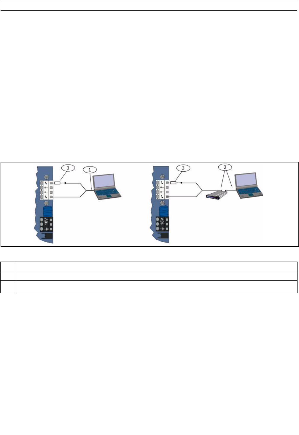
Direct Connect
Select this method to establish a local, on-site connection between the RPS PC (or laptop)
and the control panel.
1. On the Telco side of the phone line, ensure that Tip and Ring are disconnected.
2. Connect the internal modem on the RPS PC, or an external modem, to the control panel.
Refer to Figure 4.1, Page 35.
Figure 4.1 Modem Connections
3. If the first communication attempt fails, connect a 270 Ω to 330 Ω, ¼ W resistor in series
with the Tip House side. Refer to Figure 4.1, Page 35.
Network
Select this method to establish a network connection between the RPS PC (or laptop) and
the control panel using the ITS-DX4020-G or the DX4020.
1 Connection using internal modem
2 Connection using external modem
3270 Ω to 330 Ω, ¼ W resistor (for Direct Connection option only)
36 en | Programming Access Options Easy Series
F01U087835 | 02 | 2008.10 System Reference Guide Bosch Security Systems, Inc.
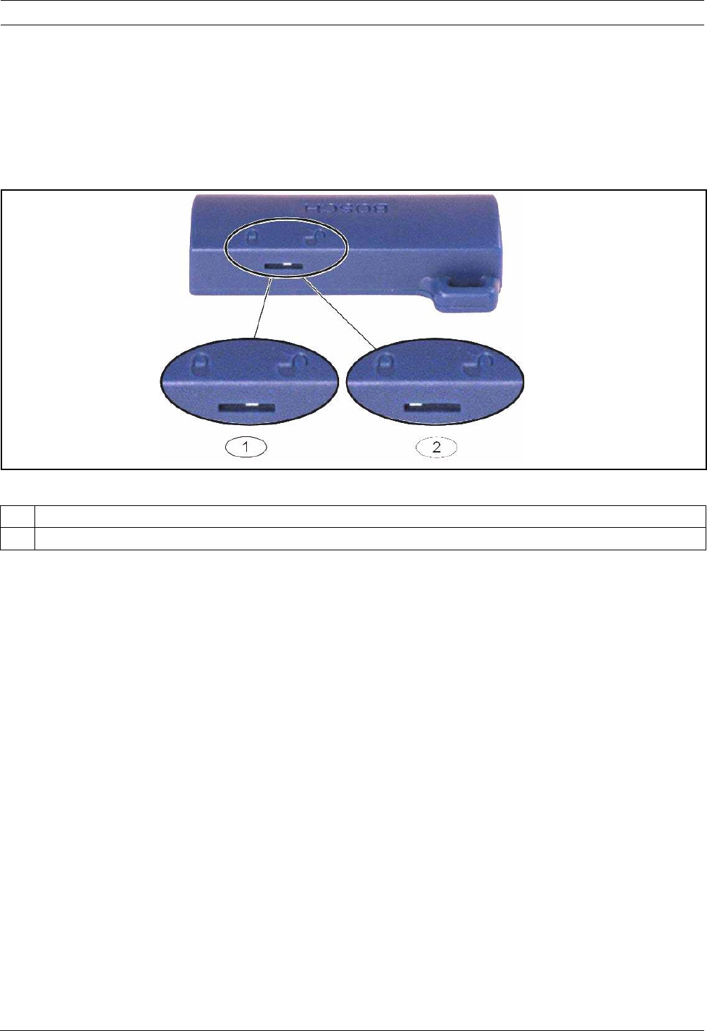
4.3 Programming Keys
After you program a control panel using the Phone Menus or RPS, you can use a programming
key to transfer data from that control panel to another control panel. You can also use a
programming key to back up control panel data.
1. If the system is on, turn it off.
2. Place the key's lock switch in the desired position. Refer to Figure 4.2.
Figure 4.2 Programming Key Lock Positions
3. Insert the key into the control panel board.
–Auto Transfer: If Expert Programming Item Number 123 = 1 (refer to Programming
Key Auto Transfer in Section 5.2.2 System Programming Items, page 43), the
programming key automatically transfers data depending on the position of the lock
switch.
–Manual Transfer: If Expert Programming Item Number 123 = 0, you must use the
Installer Menu to access the programming key.
The control center announces when data transfer is completed.
4. When the (√) LED flashes green, data transfer is successful.
If the (√) LED flashes red, the data transfer is unsuccessful. Remove and reinstall the key.
1 Send data from control panel to key
2 Send data from key to control panel
Easy Series Programming | en 37
Bosch Security Systems, Inc. System Reference Guide F01U087835 | 02 | 2008.10
5 Programming
Table 5.1 System Programming Methods
Method Description
Basic Programming Basic Programming consists of a voice menu that contains the essential programming
items. Generally, finishing this programming section is usually all that is required for a
complete system.
Expert Programming Expert Programming allows access to all programming categories for full system
configuration. Only use expert programming if you have a special programming
requirement.
i
NOTICE!
You can program control panels using the remote programming software RPS. Like Expert
Programming, RPS allows access to all programming categories. For more information on RPS
and how to use a programming key to streamline a multiple-panel install, refer to
Section 4 Programming Access Options, page 33.
i
NOTICE!
For additional instructions and information for select programming items, refer to
Section 11 Programming Details and Defaults, page 102.
For country code specific defaults for programming items, refer to Section 11.3 Country Code
Specific Default Programming Codes, page 108.
38 en | Programming Easy Series
F01U087835 | 02 | 2008.10 System Reference Guide Bosch Security Systems, Inc.
5.1 Basic Programming
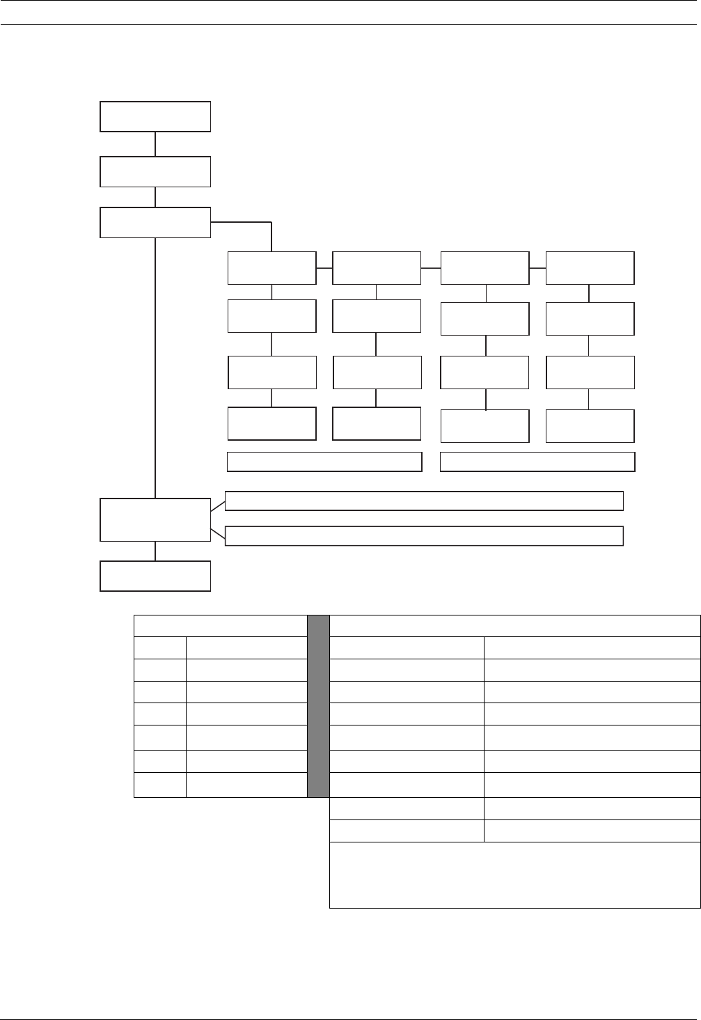
5.1.1 Enter Basic Programming
1. Select a system access option. Refer to Section 4.1 System Access by Phone, Page 33.
2. Enter the installer passcode to enter the Installer Phone Menu. Refer to
Section 2.7 Configure the System from the Installer Phone Menu, page 22.
3. Press [3] to enter Basic Programming. Refer to the figure below for the Basic
Programming Menu options.
Installer
Phone
Menu
Programming
Key
Custom
Messages
Two-Way
Voice Session
Expert
Programming
Basic
Programming
User Menu
System
Maintenance
Points
Report Configuration
Outputs
Country Code
Exit basic programming
1
2
3
4
#
Record point description
Set point type
Exit points
1
2
#Enter account number
Configure report destinations
Exit report configuration
1
2
#
Select output function
Exit outputs
1
#
Exit installer menu and end phone session.
4
5
6
7
#
1
3
2
3Remote Programming Success
Installer passcode
4-digit default: 5432
6-digit default: 543211

Easy Series Programming | en 39
Bosch Security Systems, Inc. System Reference Guide F01U087835 | 02 | 2008.10
5.1.2 Points
Points Enter a point number from 1 to 32.
1 Record Point Description
For example, if Point 1 is located at the building's front door, say "Front Door" at the tone.
When recording your description, do not press any buttons on your phone until prompted.
Press [1] to continue programming the selected point.
Press [2] to re-record your current point description.
2 Set Point Type (Refer to Point Type
table)
Press [1] to select the current option.
Press [2] to hear more options.
Press [#] to exit Point Type.
Point Types:
– Disabled
– Perimeter (Entry or Exit)
– Interior (Follower)
– Perimeter Instant
– 24-Hour
– Fire Verified
– Fire Verified
– Fire Instant
Point Types (cont.):
– Silent Panic
– Interior Walkthrough
– Perimeter Exit Cancel
– Momentary Keyswitch
– Maintained Keyswitch
– 24-Hour Trouble
– User Emergency
# Exit Points
Return to the Installer Menu.
40 en | Programming Easy Series
F01U087835 | 02 | 2008.10 System Reference Guide Bosch Security Systems, Inc.
5.1.3 Report Configuration
Table 5.2 Account Number and Phone Number/IP Address Entries
Report Configuration
[1]
Account Number
[2]
Report Destination
[3]
Remote
Program Success
[#]
Exit
Phone Number
or IP Address
Format
[1]
Route 1 Primary
[#]
Exit
Format
[#]
Exit
Format
[#]
Exit
Format
[#]
Exit
ROUTE 1 ROUTE 2
Phone Number: Enter phone number to dial and follow prompts.
IP Address: Enter “#” as first character, then follow prompts.
[2]
Route 1 Backup
[3]
Route 2 Primary
[4]
Route 2 Backup
Phone Number
or IP Address
Phone Number
or IP Address
Phone Number
or IP Address
Account Number Entries Phone Number/IP Address Entries
Entry Key Press Entry Key Press
0 to 9 [0] to [9] 0 to 9 [0] to [9]
B[*][1] *[*][*]
C[*][2] #[*][#]
D[*][3] .[*]1
E[*][4] Pause [#]
F[*][5] Exit with Save [#][#]2
Disable phone number [0][#]
Disable IP address 240.0.0.0
1 [*] = . between each IP address notation.
2 Press [#] twice within two seconds to exit without saving
your entry.
Easy Series Programming | en 41
Bosch Security Systems, Inc. System Reference Guide F01U087835 | 02 | 2008.10
5.1.4 Outputs
Output devices consist of horns, bells, strobes, or sirens.
Outputs Enter an output number from 1 to 8
1Set Output Function
– Press [1] to select the current
option.
– Press [2] to hear more options.
– Press [#] to exit Output Function.
Output Functions:
– Disabled
–Intrusion
– Intrusion Latching
–Fire
– Fire Latching
– Intrusion and Fire
– Intrusion and Fire Latching
– System Reset
Output Functions (cont.):
–System On
– System Ready
–Key Fob On/Off
– Key Fob 2-sec Pulse
– User Controlled
– Interior Intrusion and Fire
– System On (Unoccupied)
# Exit Points
Return to Installer Menu.
i
NOTICE!
When the installer PIN is entered at the keypad or phone, a 3 sec time window starts. During
that time window, a tamper alarm activates the interior siren for only 1 sec. Open the
enclosure door during this time to silence the sirens during maintenance. Once the enclosure
is closed, tamper alarm is restored after a 3 min delay. Tampers are logged and reported.
!
WARNING!
If you modify system parameters you are responsible for maintaining the system within the
scope of the standard and regulations that apply to the hardware and/or the system in which
it is used. In a NF A2P compliant installation, use only NF A2P listed components, and check
that each parameter is in the authorized range.
42 en | Programming Easy Series
F01U087835 | 02 | 2008.10 System Reference Guide Bosch Security Systems, Inc.
5.2 Expert Programming
Each category consists of several related programming items. Each programming item is
assigned a three- or four-digit number.
For No. 4 in the next figure, perform these steps:
1. Enter an expert programming item number. For example, 201, Phone Line Supervision.
2. Enter the desired value using your phone's keypad. For example, press [1] to enable
phone line supervision.
3. Repeat Steps 1 and 2 to configure other programming items, or press [#] to exit Expert
Programming.
The following sections list programming items, item numbers, possible selections, and default
values. Record custom values in the Entry column next to the respective default value.
Installer
Phone
Menu
Programming
Key
Custom
Messages
Two-Way
Voice Session
Expert
Programming
Basic
Programming
User Menu
System
Maintenance
Exit installer menu and end phone session.
4
5
6
7
#
1
3
2
Installer passcode
4-digit default: 5432
6-digit default: 543211

Easy Series Programming | en 43
Bosch Security Systems, Inc. System Reference Guide F01U087835 | 02 | 2008.10
5.2.1 ROM Firmware Version Items
5.2.2 System Programming Items
Programming Item Item
Number
Description
Control Panel Firmware Version 090 System announces the control panel’s firmware
version.
Control Center 1 Firmware Version 091 System announces the control center’s firmware
version.
Control Center 2 Firmware Version 092
Control Center 3 Firmware Version 093
Control Center 4 Firmware Version 094
Programming Item Item
Number
Selections Manuf.
Default
Country Code (refer to
Section 11.2 Country Codes)
102 00 to 65 58
Enclosure Tamper Enabled 103 0 = Disabled
1 = Enabled
1
Fire Bell Cut-Off Time 107 0 to 90 min 5
Intrusion Bell-Cut off Time 108 0 to 90 min 5
Intrusion Abort Window 110 15 to 45 sec 30
Fire Alarm Cancel Window 111 0 to 10 min 0
Intrusion Cancel Window 112 5 to 10 min 5
Chime Tone Select 114 1 = Chime door bell
2 = Single chime
3 = Standard door bell
1
Chime Mode Operation After System
Off
115 0 = Off
1 = On
2 = Follows previous setting
0
Automatic Test Report Frequency 116 0 = None
1 = Daily
2 = Weekly
3 = Monthly
0
Access Code 119 6 digits, using 0 to 9 999999
Daylight Saving Time Operation 121 0 = None
1 = North America (before 2007)
2 = Europe and Asia
3 = Tasmania, Australia
4 = Rest of Australia
5 = New Zealand
6 = Cuba
7 = South America and Antarctica
8 = Namibia, Africa
9 = USA after 2006
1
Installer Passcode Override Enabled 122 0 = Disabled
1 = Enabled
1

44 en | Programming Easy Series
F01U087835 | 02 | 2008.10 System Reference Guide Bosch Security Systems, Inc.
Programming Key Auto Transfer 123 0 = Enable the programming key from the Installer
Menu.
1 = Programming key automatically sends or
receives stored programming data.
1
Point Alarm Verification 124 0 = None
1 = Cross zone
2 = Intelligent threat assessment
3 = Confirmed alarms 1
4 = Confirmed alarms 2
0
Faulted Points Allowed Threshold 125 0 to 8 3
Exit Delay 126 45 to 255 sec 60
Entry Delay 127 30 to 255 sec 30
Exit Time Restart 128 0 = User cannot reset Exit Delay timer
1 = User can reset Exit Delay timer one time
1
Recent Close Enabled 129 0 = Report not sent
1 = Report sent
1
Swinger Bypass Count 131 0-15 1
Auto Protection Level 132 0 = System turns on (unoccupied).
1 = System only turns on (unoccupied) if a
perimeter point is faulted during Exit Delay.
1
System On Order Options 133 1 = "Stay," "Leave," "Custom"
2 = "Stay," "Custom," "Leave"
3 = "Leave," "Stay," "Custom"
4 = "Leave," "Custom," "Stay"
5 = "Custom," "Leave," "Stay"
6 = "Custom," "Stay," "Leave";
1
Cross Zone Timer 134 60 to 3600 sec 120
Clear Alarm Memory 136 0 = By user, 1 = By master user 0
Latching Point and Enclosure Tamper 137 0 = Any user can clear condition
1 = Only the installer can clear condition
0
Latching System Device Tamper 138 0 = Any user can clear condition
1 = Only the installer can clear condition
0
Verbose System Test Enabled 139 0 = Test results announced only at end of all tests
1 = Test results announced after each test
1
Demo Mode 140 0 = Telephone messages heard only on phone
1 = Telephone messages heard on phone and
control centers
2 = Turn announcement of telephone messages over
the control center on or off at the control center
0
Restrict Installer Passcode 142 0 = Master user not needed
1 = Master user needed
0
Test Report Hour 143 0 to 23
Test Report Minute 144 0 to 59 0
Test Report Day of Week 145 0 to 6, where 0 = Sunday and 6 = Saturday 0
Programming Item Item
Number
Selections Manuf.
Default

Easy Series Programming | en 45
Bosch Security Systems, Inc. System Reference Guide F01U087835 | 02 | 2008.10
Test Report Day of Month 146 1 to 28 1
Clear Confirmed Alarm Memory 147 0 = User can clear a confirmed alarm
1 = Only the installer can clear a confirmed alarm
0
Arming Beeps/Graduated
Annunciation
148 0 = No arming beeps or outputs during Entry Delay
1 = Outputs activate during Entry Delay, but no
arming beeps occur.
2 = Sound arming beeps, but outputs do not
activate during Entry Delay
3 = Sound arming beeps, and outputs activate
during Entry Delay
0
Wireless Jam Detect Level 150 0 to 15 12
Key Fob Arming 153 0 = Do not turn system on if there are faulted points
1 = Force arm faulted points if the number of
faulted points is within the range set in Expert
Programming Item Number 125
2 = Force arm faulted points even if the number of
faulted points exceeds the range set in Expert
Programming Item Number 125
0
Two-Way Voice Session Configuration 158 0 = Allow at any time
1 = Allow only during alarm conditions
0
Start Arming with Faulted Points 159 0 = Force arm all faulted points
1 = Exit Delay starts with faulted points
1
Speak Active Faults 160 0 = "Call for Service" announced
1 = Fault condition announced
0
Wireless Transmission Attenuation 161 Temporary attenuation for installation and
maintenance only. Not intended for normal
operation.
0 = None (normal operation)
1 = 3 dB
2 = 6 dB
3 = 9 dB
4 = 12 dB
0
Missing Wireless Device Conditions 162 0 = Creates a tamper condition (required for
EN50131-compliant countries).
1 = Creates a trouble condition.
0
Silence Trouble Tones 163 0 = All trouble tones announced
1 = Fire and 24-Hour trouble tones announced
0
System Inactivity Time (Hours) 164 0 to 255 0
System Inactivity Time (Days) 165 0 to 255 0
System Inactivity Time (Weeks) 166 0 to 255 0
Force Arm/Exit Error 167 0 = Off-normal points create an Exit Error at the end
of Exit Delay
1 = Off-normal points are force armed at the end of
Exit Delay
0
Programming Item Item
Number
Selections Manuf.
Default

46 en | Programming Easy Series
F01U087835 | 02 | 2008.10 System Reference Guide Bosch Security Systems, Inc.
Audio Verification Command Set 168 0 = Complies with SIA AV-01-1997.11
1 = Use alternate verification command set
Key Fob Duress 601 0 = Duress event disabled
1 = Duress event enabled
0
Key Fob Button Configuration 616 0 = Status request only
1 = Turn system on (occupied)
2 = Turn system on (custom protection)
3 = Turn output on or off
4 = Turn output on for 2 sec.
0
Key Fob Button Configuration 626 0
Default = Country-specific default. Select this programming item to hear the updated default value, or refer to Section 11.3 Country
Code Specific Default Programming Codes, page 108.
Programming Item Item
Number
Selections Manuf.
Default

Easy Series Programming | en 47
Bosch Security Systems, Inc. System Reference Guide F01U087835 | 02 | 2008.10
5.2.3 Communicator Programming Items
Route Destination Items
i
NOTICE!
To enable reporting, configure the following programming items:
– Account Number (Expert Programming Item Number 100)
– Route 1 Primary Destination (Expert Programming Item Number 206)
– Format for Route 1 Primary Destination (Expert Programming Item Number 211)
Programming Item Item
Number
Selections Manuf.
Default
Account Number 100 4 or 6 digits, using 0 to 9 and B to F.
Refer to Table 5.2, Page 40 for account number,
phone number, and IP address entry instructions.
000000
Phone Line Supervision 201 0 = Unsupervised.
1 = Supervised.
0
PSTN or GSM Connection 202 0 = PSTN telephone line
1 = ITS-DX4020-G Wireless Phone using GSM
Voice Format Repeat Count 203 1 to 15 3
Voice Format Message Delivery
Attempts
204 1 to 5 in increments of 5 sec 1
Dial Tone Detect 205 0 = Do not wait for dial tone.
1 = Wait for dial tone.
1
Route 1 Primary Destination 206 Enter a phone number (up to 32 digits) or IP address
(000.000.000.000 to 255.255.255.255) for each
destination:
0 to 9 = [0] to [9]
* = [*][*]
# = [*][#]
Pause = [*][1]
Exit with save = [#]
Exit without save = [#][#]
Press [#] twice within two seconds to exit without
saving your entry.
Disable phone number = [0][#]
Disable IP address = 240.0.0.0
0
Route 1 Backup Destination 207 0
Route 2 Primary Destination 208 0
Route 2 Backup Destination 209 0
SMS Service Provider Number 210 Up to 32 digits. 0
Format for Route 1 Primary Destination 211 0 = Disabled
1 = Contact ID
2 = SIA
3 = Voice
4 = SMS Text
5 = Fast Format
6 = Network (requires a 4-digit account number)
0
Format for Route 1 Backup Destination 212 0
Format for Route 2 Primary Destination 213 0
Format for Route 2 Backup Destination 214 0
Call Waiting Disable 215 Enter a 3-digit string.
* = [*][*]; # = [*][#]
0
Emergency Call Override Number 216 Enter a 3-digit emergency number, such as 911. 000
Emergency Call Override Number Delay 217 0 to 60 min 5

48 en | Programming Easy Series
F01U087835 | 02 | 2008.10 System Reference Guide Bosch Security Systems, Inc.
Alternate Communication Items
Auto Detect Pulse Dial 218 0 = Tone dialing only
1 = Auto Detect Pulse or Tone
0
Phone Answer Ring Count 222 1 to 255 rings
Enter 11 to bypass an answering machine.
10
Bell Test 223 0 = Disabled
1 = Enabled
0
Default = Country-specific default. Select this programming item to hear the updated default value, or refer to Section 11.3 Country
Code Specific Default Programming Codes, page 108.
Programming Item Item
Number
Selections Manuf.
Default
Programming Item Item
Number
Selections Manuf.
Default
Port Number for Route Destination:
Route 1 Primary = 241
Route 1 Backup =242
Route 2 Primary = 243
Route 2 Backup = 244
241 0 to 65535 7700
242 7700
243 7700
244 7700
Heartbeat for Route Destination:
Route 1 Primary = 281
Route 1 Backup =282
Route 2 Primary = 283
Route 2 Backup = 284
281 0 = Disabled
1 to 65535 min
0
282 0
283 0
284 0
Acknowledge Wait Time for Route Destination
Route 1 Primary = 285
Route 1 Backup =286
Route 2 Primary = 2887
Route 2 Backup = 288
285 5 to 255 sec 15
286 15
287 15
288 15
Anti-Replay for Route Destination:
Route 1 Primary = 289
Route 1 Backup =290
Route 2 Primary = 291
Route 2 Backup = 292
289 0 = Disabled
1 = Enabled
1
290 1
291 1
292 1
Heartbeat Attempt for Route Destination:
Route 1 Primary = 293
Route 1 Backup =294
Route 2 Primary = 295
Route 2 Backup = 296
293 1 to 99 5
294 5
295 5
296 5
Extend Heartbeat Period 297 0 = Disabled
1 to 255 min

Easy Series Programming | en 49
Bosch Security Systems, Inc. System Reference Guide F01U087835 | 02 | 2008.10
5.2.4 RPS Configuration Items
Programming Item Item
Number
Selections Manuf.
Default
RPS Passcode 118 6 digits, using 0 to 9 and A to F. 123456
RPS Automatic Call In Frequency 224 0 = Never
1 = Daily
2 = Weekly
3 = Monthly
RPS Automatic Call In Time (Hours) 225 0 to 23
RPS Automatic Call in Time
(Minutes)
226 0 to 59
RPS Automatic Call in Time (Day of
Week)
227 0 to 6, where 0 = Sunday and 6 = Saturday
RPS Automatic Call in Time (Day of
Month)
228 1 to 28
RPS Automatic Call in Phone
Number
229 Enter a phone number (up to 32 digits) or IP address
(000.000.000.000 to 255.255.255.255) for each
destination:
0 to 9 = [0] to [9]
* = [*][*]
# = [*][#]
Pause = [*][1]
Exit with save = [#]
Exit without save = [#][#]
Press [#] twice within two seconds to exit without saving
your entry.
Disable phone number = [0][#]
Disable IP address = 240.0.0.0
RPS Automatic Call in Method 245 0 = Phone number
1 = IP address
RPS Port Number 246 0 to 65535 7750

50 en | Programming Easy Series
F01U087835 | 02 | 2008.10 System Reference Guide Bosch Security Systems, Inc.
5.2.5 Route Reporting Options
Point Report and Restoral Routing
System On and Off Report Routing
Programming Item Item
Number
Manuf.
Default
Programming Item Item
Number
Manuf.
Default
Point Reports and Restorals (all)* 301 3 Fire Trouble 328 3
Intrusion Alarm 307 3 Fire Trouble Restoral 329 3
Intrusion Alarm Verified 308 3 24-Hour Trouble 331 3
Intrusion Alarm Unverified 309 3 24-Hour Trouble Restoral 332 3
Intrusion Alarm 24-hr 310 3 Point Missing 333 3
Intrusion Alarm 24-hr Restoral 311 Point Missing Restoral 334 3
Intrusion Alarm Restoral 312 3 Supervisory Alarm 335 3
Duress 313 3 Supervisory Alarm Restoral 336 3
Fire Alarm 315 3 Wireless Point Low Battery 360 3
Fire Alarm Unverified 316 3 Wireless Point Low Battery Restoral 361 3
Fire Alarm Restoral 317 3 Fire Cancel 371 3
Panic 318 3 Point Tamper 388 3
Cancel 323 3 Point Tamper Restoral 397 3
Intrusion Trouble 324 3 Cross Zone Trouble 393 3
Intrusion Trouble Restoral 325 3 Alarm Recent Close 394 3
Intrusion Zone Bypass 326 3 Panic Restoral 399 3
Intrusion Zone Bypass Restoral 327 3 Cross Zone Trouble Restoral 400 3
*Enter a value to globally set all of the following reports to the same value.
To modify one a specific report, enter a value in that report’s item number:
0 = Neither route
1 = Route 1 only; Primary and Backup
2 = Route 2 only; Primary and Backup
3 = Both routes; Primary and Backup
Programming Item Item
Number
Manuf.
Default
Programming Item Item
Number
Manuf.
Default
System On and Off*
(open and close) Reports (all)
302 3 Open 341 3
Exit Error 314 3 Open Keyswitch 342 3
Recent Closing 330 3 Open Remote 343 3
Close (System On) Unoccupied 337 3 Close (System On) Custom 344 3
Close (System On) Occupied 338 3 Opening by Guard Code 386 3
Close Keyswitch 339 3 Partial Close (System On) 403 3
Close Remote 340 3 3
*Enter a value to globally set all of the following reports to the same value.
To modify only a specific report, enter a value in that report's item number.
0 = Neither route
1 = Route 1 only; Primary and Backup
2 = Route 2 only; Primary and Backup
3 = Both routes; Primary and Backup

Easy Series Programming | en 51
Bosch Security Systems, Inc. System Reference Guide F01U087835 | 02 | 2008.10
System Report and Restoral Routing
Programming Item Item
Number
Manuf.
Default
Programming Item Item
Number
Manuf.
Default
System Reports and Restorals (all)1303 3 Communication Restoral 352 3
User Emergency2319 3 Control Center Supervision Fail 353 3
User Fire3320 3 Control Center Supervision Restoral 354 3
User Fire Restoral 321 3 Control Center Tamper 355 3
User Panic 322 3 Control Center Tamper Restoral 356 3
AC Fail 345 3 System Inactive 385 3
AC Fail Restoral 346 3 Watchdog Reset 390 3
Auto System Test Normal 347 3 Passcode Tamper 391 3
Auto System Test Off-Normal 348 3 Date/Time Changed 410 3
Auxiliary Power Fault 349 3 Network Fail 413 3
Auxiliary Power Restoral 350 3 Network Restoral 414 3
Communication Fail 351 3 3
Local Programming Success* 357 3 Bus Device Trouble 373 3
Low Battery 358 3 Bus Device Trouble Restoral 374 3
Low Battery Restoral 359 3 ROM Fault 375 3
Communication Test, Manual 362 3 Bell Trouble 376 3
Phone Line Fault 363 3 Bell Restoral 377 3
Phone Line Fault Restoral 364 3 Walk Test End 378 3
Remote Programming Failure 365 3 Walk Test Start 379 3
Remote Programming Success 366 3 Bus Device Missing 380 3
Wireless Receiver Jammed 367 3 Bus Device Missing Restoral 381 3
Wireless Receiver Jammed Restoral 368 3 Battery Missing 382 3
Bus Device Tamper 369 3 Battery Missing Restoral 383 3
Bus Device Tamper Restoral 370 3 RAM Checksum Failed 384 3
1 Enter a value to globally set all of the following reports to the same entry.
2 To modify only a specific report, enter a value in that report's item number.
0 = Neither route
1 = Route 1 only; Primary and Backup
2 = Route 2 only; Primary and Backup
3 = Both routes; Primary and Backup
3To enable the control center's emergency buttons, set Expert Programming Items 889, 888, and 890.

52 en | Programming Easy Series
F01U087835 | 02 | 2008.10 System Reference Guide Bosch Security Systems, Inc.
Global Report Routing Items
5.2.6 Point Programming Items
Programming Item Item
Number
Selections Manuf.
Default
Communicator Disable 304 0 = Enable reporting
1 = Disable reporting (local-only system)
0
Route Attempts 305 1 to 20 10
Send Reports During Walk Test 306 0 = No reports
1 = Only Walk Test Start and Walk Test End reports
0
Default = Country-specific default. Select this programming item to hear the updated default value, or refer to Section 11.3 Country
Code Specific Default Programming Codes, page 108.
Programming Item Number
(bold digits = Point Number)
Programming Item Selections
9011, 9021, 9031, 9041...
9101...9151...9201...9321
Point Type 0 = Disabled
1 = Perimeter
2 = Interior
3 = Perimeter Instant
4 = 24-Hour
5 = Fire Verified*
6 = Fire Instant
7 = Silent Panic
8 = Interior Walkthrough
9 = Perimeter Exit Cancel
11 = Momentary Keyswitch
12 = Maintained Keyswitch
13 = 24-Hour Trouble
14 = User Emergency
9012, 9022, 9032, 9042...
9102...9152...9202...9322
Circuit Style 0 = Dual 2.2 kΩ alarm and tamper circuit
2 = Single 2.2 kΩ alarm circuit
9013, 9023, 9033, 9043...
9103...9153...9203...9323
Include in Custom Protection 0 = Point not included
1 = Point included
9014, 9024, 9034, 9044...
9104...9154...9204...9324
Cross Zone/Exit Route 0 = Cross zoning disabled, point is on the exit
route.
1 = Cross zoning enabled, point is on the exit
route
2 = Cross zoning disabled, point is not on the exit
route (must force arm).
3 = Cross zoning enabled, point is not on the exit
route.
9015, 9025, 9035, 9045...
9105...9155...9205...9325
Response Time 1 to 10 in 50 ms increments

Easy Series Programming | en 53
Bosch Security Systems, Inc. System Reference Guide F01U087835 | 02 | 2008.10
Table 5.3 Manuf. Default for Point Programming Items
9016, 9026, 9036, 9046...
9101...9151...9201...9321
Alarm Verification 0 = Disable alarm verification
1 = Enable alarm verification
9018, 9028, 9038, 9048...
9108...9158...9208...9328
Wireless Detector Sensitivity Motion Detector (PIR and dual)
0 = Standard
4 = Intermediate
Inertia Detector: Gross Attack Options
0 = Tap off, low sensitivity
1 = Tap off, low/medium sensitivity
2 = Tap off, medium/high sensitivity
3 = Tap off, high sensitivity
Inertia Detector: Minor Attack Options
8 = Tap on, 8 taps, low sensitivity
9 = Tap on, 8 taps, low/medium sensitivity
10 = Tap on, 8 taps, medium/high sensitivity
11 = Tap on, 8 taps, high sensitivity
12 = Tap on, 4 taps, low sensitivity
13 = Tap on, 4 taps, low/medium sensitivity
14 = Tap on, 4 taps, medium/high sensitivity
15 = Tap on, 4 taps, high sensitivity
Programming Item Number
(bold digits = Point Number)
Programming Item Selections
Point Type (9011 ... 9321): Point 1 = 6, Points 2 - 5 = 1, Points 6 - 8 = 2, Points 9 - 32 = 0
Circuit Style (9012 ... 9322): Points 1 - 32 = 2
Custom Protection (9013 ... 9323): Points 1 - 32 = 0
Cross Zone Enabled (9021 ... 9321): 1
Response Time (9015 ... 9085): Points 1 - 8 only = 6
Wireless Sensitivity (9018 ... 9328): Points 1 - 32 = 0
Alarm Verification (9016 ... 9326): Points 1 - 32 = 0

54 en | Programming Easy Series
F01U087835 | 02 | 2008.10 System Reference Guide Bosch Security Systems, Inc.
5.2.7 Output Programming Items
Programming Item Item
Number
Selections Manuf.
Default
Fire Output Cadence 600 0 = Temporal Code 3 cadence
1 = Pulse cadence
(two-sec on, two-sec off)
0
Output 1 Function (wired) 611 0 = Disabled
1 = Intrusion
2 = Intrusion Latching
3 = Fire
4 = Fire Latching
5 = Intrusion and Fire
6 = Intrusion and Fire Latching
7 = System Reset
8 = System On
9 = System Ready
10 = Key Fob On/Off
11 = Key Fob 2-sec Pulse
13 = User Controlled
14 = Interior Intrusion and Fire
15 = System On (Unoccupied)
16 = Intrusion and Fire 2
5
Output 2 Function (wired) 621 5
Output 3 Function (wired) 631 5
Output 4 Function (wired) 641 7
Output 5 Function (wireless) 651 5
Output 6 Function (wireless) 661 0
Output 7 Function (wireless) 671 0
Output 8 Function (wireless) 681 0
Output 4 Supervised Speaker Driver
(wired)
642 0 = Supervised 8 Ω speaker driver
1 = Unsupervised open collector
0
Default = Country-specific default. Select this programming item to hear the updated default value, or refer to Section 11.3 Country
Code Specific Default Programming Codes, page 108.
i
NOTICE!
When programming a wireless output (for example, a siren or relay module), do not select an
output function that requires the output to activate for an extended period (for example
System Ready).

Easy Series Programming | en 55
Bosch Security Systems, Inc. System Reference Guide F01U087835 | 02 | 2008.10
5.2.8 Control Center Programming Items
Speech Configuration Items
Global Control Center Items
These programming items affect all control centers connected to the control panel.
To send a user fire, emergency (medical) or panic report, the appropriate control center
button and report must be enabled. Refer to Section 5.2.5 Route Reporting Options on Page 50
to enable reports.
Check the appropriate box in the Easy Series User Guide (P/N: F01U0xxxxx) to identify which
buttons are enabled.
Programming Item Item
Number
Selections Manuf.
Default
Alarm Message Minimum Repeat Time 880 (1 to 255 hrs). 12
"No Alarm Report Sent" Announcement 883 0 = Announcement disabled.
1 = Announcement enabled.
1
"Cancel Report Sent" Announcement 884 1
Time Format 887 0 = Determined by voice module
1 = Always use 12-hr mode
2 = Always use 24-hr mode
0
Programming Item Item
Number
Selections Manuf.
Default
Fire Button Alarm 888 0 = Disabled.
1 = Enabled.
0
Medical Button Alarm 889 0 = Disabled.
1 = Enabled
0
Panic Button Alarm 890 0 = Disabled.
1 = Enabled (audible).
2 = Enabled (silent).
0
One Button Arming
[i]
891 0 = Disabled (token or passcode required).
1 = Enabled (token or passcode is not required).
0
Invalid Passcode Attempt Limit 892 3 to 8. 3
Control Center Lockout Time 893 1 to 30 min. 3
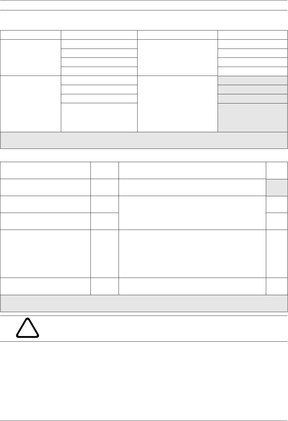
56 en | Programming Easy Series
F01U087835 | 02 | 2008.10 System Reference Guide Bosch Security Systems, Inc.
Individual Control Center Items
5.2.9 User Programming Items
Programming Item Item Number Selections Manuf. Default
Control Center
Brightness
Control Center 1: 811 1 (dim) to 5 (bright). Control Center 1: 5
Control Center 2: 821 Control Center 2: 5
Control Center 3: 831 Control Center 3: 5
Control Center 4: 841 Control Center 4: 5
Control Center
Backlight Extinguish
Mode
Control Center 1: 814 0 = Always on.
1 = Dim until user presence is
detected.
2 = Off until user presence is
detected.
3 = Off until user presents
token or enters passcode.
Control Center 1: 0
Control Center 2: 824 Control Center 2: 0
Control Center 3: 834 Control Center 3: 0
Control Center 4: 844 Control Center 4: 0
Default = Country-specific default. Select this programming item to hear the updated default value, or refer to Section 11.3 Country
Code Specific Default Programming Codes, page 108.
Programming Item Item
Number
Selections Manuf.
Default
Passcode Length 861 Set the length of all passcodes
(4 or 6 digits).
4
Installer Passcode (User 0) 7001 Four-digit Range: 1111 to 5555
Six-digit Range: 111111 to 555555
5432
543211
Master User Passcode (User 1) 7011 1234
123455
Duress User (User 22) Enabled 862 0 = Duress user disabled
1 = Duress user enabled
2 = Guard code enabled
Duress User passcode:
Six digits: 111111
Four digits: 1111
0
RFID Token Password 863 Use this item to prevent unauthorized copying of tokens
(00000000 to FFFFFFFF).
123456
78
Default = Country-specific default. Select this programming item to hear the updated default value, or refer to Section 11.3 Country
Code Specific Default Programming Codes, page 108.
!
CAUTION!
Do not change the RFID Token Passwords item once tokens are added to the system.

Easy Series Programming | en 57
Bosch Security Systems, Inc. System Reference Guide F01U087835 | 02 | 2008.10
5.2.10 Factory Default
5.3 Exit Programming
Press [#] repeatedly until the system says "goodbye." This ends the phone session.
Programming Item Item
Number
Selections
Factory Default 9999 Enter 9999 to restore all factory default values. All programming items,
except for the country code, are reset when you restore the factory default
values. This item also deletes all wireless data, but does not default the
wireless hub.
!
WARNING!
For NF A2P installations, once the panel is configured, check that all parameters are within the
range of authorized values. Refer to Section 12.7 EN50131 Requirements, page 119.

58 en | Control Panel Event Codes (SIA and Contact ID) Easy Series
F01U087835 | 02 | 2008.10 System Reference Guide Bosch Security Systems, Inc.
6 Control Panel Event Codes (SIA and Contact ID)
Event SIA Report Contact ID Report
Intrusion Alarm BA Burglary Alarm 1 130 Burglary
Intrusion Alarm Verified BV Burglary Alarm Verified 1 139 Burglary
Intrusion Alarm Unverified BG Unverified Event Burglary 1 130 Burglary
Intrusion Alarm 24-hr BA Burglary Alarm 1 133 24 Hour (Safe)
Intrusion Alarm 24-hr Restoral BH Burglary Alarm Restore 3 133 Restoral
Intrusion Alarm Restoral BR Burglary Restoral 3 130 Burglary
Duress HA Hold Up Alarm 1 121 Duress
Exit Error EA Exit Alarm 1 374 Exit Error (zone)
Fire Alarm FA Fire Alarm 1 110 Fire
Fire Alarm Unverified FG Unverified Event-Fire 1 110 Fire
Fire Alarm Restoral FH Fire Alarm Restore 3 110 Fire
Panic HA Holdup Alarm 1 120 Panic
Panic Restoral HH Holdup Alarm Restore 3 120 Panic
User Emergency (Medical) QA Emergency Alarm 1 101 Personal Emergency
User Fire FA Fire Alarm 1 110 Fire
User Fire Restoral FH Fire Alarm Restore 3 110 Fire
User Panic HA Holdup Alarm 1 120 Panic
Cancel BC Burglary Cancel 1 406 Cancel
Intrusion Trouble BT Burglary Trouble 1 380 Sensor Trouble
Intrusion Trouble Restoral BJ Burglary Trouble Restore 3 380 Sensor Trouble
Intrusion Point Bypass BB Burglary Bypass 1 570 Zone/Sensor bypass
Intrusion Point Bypass Restoral BU Burglary Unbypass 3 570 Zone/Sensor bypass
Fire Trouble FT Fire Trouble 1 373 Fire Trouble
Fire Trouble Restoral FJ Fire Trouble Restore 3 373 Fire Trouble
Recent Closing CR Recent Closing 1 459 Recent Closing
Close (System On) Unoccupied CL Closing Report 3 401 Unoccupied Arm by User
Close (System On) Occupied CL Closing Report 3 441 Occupied Arm by User
Close (System On) Custom CL Closing Report 3 441 Custom Arm by User
Close (System On) Partial CL Closing Report 3 456 Partial Arm by User
Close (System On) Keyswitch CS Closing Keyswitch (User 255) 3 409 Keyswitch O/C (User 255)
Open (System Off) OP Opening Report 1 401 O/C by User
Open (System Off) Keyswitch OS Opening Keyswitch (User
255)
1 409 Keyswitch O/C (User 255)
AC Fail AT AC Trouble 1 301 AC Loss
AC Fail Restoral AR AC Restoral 3 301 AC Loss
Auto System Test (Normal) RP Automatic Test 1 602 Period Test Report (User 0)
Auto System Test (Off-Normal) RY Test Off Normal 1 608 Period Test Report, System
Trouble Present
Auxiliary Power Fault IA Equipment Failure Condition 1 310 Ground Fault
Auxiliary Power Restoral IR Equipment Fail Restoral 3 310 Ground Fault
Communication Fail YC Communications Fail 3 310 Failure to communicate event
Communication Restoral YK Communications Restoral 3 354 Failure to communicate event
Control Center Supervision Fail EM Expansion Device Missing 1 333 Expansion module failure
Control Center Supervision
Restoral
EN Expansion Missing Restore 3 333 Sensor Trouble
Control Center Tamper ES Expansion Device Tamper 1 341 Expansion Device Tamper
Control Center Tamper Restoral EJ Expansion Device Tamper
Restore
3 341 Expansion Device Tamper
Local Programming LX Local Programming Ended 1 628 Program mode exit
Low Battery YT System Battery Trouble 1 302 Low System Battery
Low Battery Restoral YR System Battery Restoral 3 302 Low System Battery
Communication Test RX Manual Test 1 601 Manual trigger test report
Phone Line Fault LT Phone Line Trouble 1 351 Telco 1 fault

Easy Series Control Panel Event Codes (SIA and Contact ID) | en 59
Bosch Security Systems, Inc. System Reference Guide F01U087835 | 02 | 2008.10
Phone Line Fault Restoral LR Phone Line Restoral 3 351 Telco 1 fault
ROM Fault YF Parameter Checksum Fail 1 304 ROM Checksum Bad
Bell Trouble YA Bell Fault 1 320 Sounder/ Relay
Bell Restoral YH Bell Restored 3 320 Sounder/ Relay
Walk Test Start TS Test Start 1 607 Walk Test Mode
Walk Test End TE Test End 3 607 Walk Test Mode
Bus Device Missing EM Expansion Device Missing 1 333 Exp. Module Failure
Bus Device Missing Restoral EN Expansion Missing Restore 3 333 Exp. Module Failure
Battery Missing YM System Battery Missing 1 311 Battery Missing/Dead
Battery Missing Restoral YR System Battery Restoral 3 311 Battery Missing/Dead
RAM Checksum Failed YF Parameter Checksum Fail 1 303 RAM Checksum bad
Point Tamper TA Tamper Alarm 1 137 Tamper
Point Tamper Restoral TH Tamper Alarm Restoral 3 137 Tamper Restoral
Cross Zone Trouble BG Unverified Event - Burglary 1 378 Cross-zone Trouble
Cross Zone Trouble Restoral BR Burglary Restoral 3 378 Cross-zone Trouble
Point Missing UY Untyped Missing Trouble 1 381 Loss of Supervision - RF
Point Missing Restoral UJ Untyped Trouble Restore 3 381 Loss of Supervision - RF
Wireless Point Low Battery XT Transmitter Battery Trouble 1 384 RF Low Battery
Wireless Point Low Battery
Restoral
XR Transmitter Battery Restoral 3 384 RF Low Battery
Wireless Receiver Jammed XQ RF Interference 1 344 RF Receiver Jam Detect
Wireless Receiver Jammed
Restoral
XH RF Interference Restoral 3 344 RF Receiver Jam Detect
Bus Device Tamper XS RF Receiver Tamper 1 341 Exp Module Tamper
Bus Device Tamper Restoral XJ RF Receiver Tamper Restoral 3 341 Exp Module Tamper
Bus Device Trouble ET Expansion Trouble 1 330 System Peripheral Trouble
Bus Device Trouble Restoral ER Expansion Restoral 3 330 System Peripheral Trouble
Remote Programming Success RS Remote Program Success 1 628 Program mode exit
Remote Programming Failure RU Remote Program Fail 1 628 Program mode exit
24-Hour Trouble UA Untyped Zone Alarm 1 150 24-Hour Non-Burglary
24-Hour Trouble Restoral UR Untyped Zone Restoral 3 150 24-Hour Non-Burglary
Opening by Guard Code OR Disarm From Alarm 1 450 Exception Open/Close
System Inactive CI Fail to Close 1 454 Failed to Close
Network Fail NT Network Failure 1 350 Communication Trouble
Network Restoral NR Network Restoral 3 350 Communication Trouble
Passcode Tamper JA User Code Tamper 1 461 Wrong Code Entry
Firmware Updated YZ Service Completed 1 412 Successful Download/Access
Watchdog Reset YW Watchdog Reset 1 305 System Reset
Date/Time Change JT Time Changed 1 625 Time/Date Reset
Event SIA Report Contact ID Report

60 en | Default the System Easy Series
F01U087835 | 02 | 2008.10 System Reference Guide Bosch Security Systems, Inc.
7 Default the System
7.1 Default the Control Panel and the wLSN Hub
To restore the control panel to its factory settings, including programming data, and erase the
wireless network:
1. Remove all power to the system.
2. Remove the wLSN Hub from its base. Refer to Figure 1.1, Page 6.
3. Record the current switch settings, then set the switches as follows: S1 = 9, S2 = 8, S3 =
7. Refer to Figure 1.1, Page 6.
4. Reconnect the wLSN Hub to the base.
5. Reapply all power to the system.
6. Wait for the green LED on the wLSN Hub to turn on and then off (approximately 5 sec).
7. Remove all power to the system.
8. Disconnect the wLSN Hub from the base again, and reset the switches to their previous
settings. Do not reconnect the wLSN Hub to the base yet.
9. Reapply all power to the system.
10. Default the control panel from the Installer Menu of a phone session
(Section 2.7.2 Initiate a Phone Session from the Control Panel, Page 22), press [4] to select
Expert Programming.
11. Press [9][9][9][9] to restore all factory default values.
12. Remove all power to the system.
13. Reconnect the wLSN Hub to the base.
14. Reapply all power to the system.
15. Default all wLSN devices.
7.2 Default wLSN Devices
Defaulting a wLSN device returns it to an undiscovered state.
To default a wLSN device:
1. Remove the batteries.
2. Press and hold the tamper switch.
3. Reinsert the batteries while holding the tamper switch.
Continue to hold the tamper switch for at least 3 sec. The device's LED turns on.
4. Release the tamper switch within 5 sec. after the device's LED turns on.
The device's LED briefly turns off and then on, indicating that the device was returned to
an undiscovered state.
For specific instructions for defaulting each wLSN device, refer to the wLSN Reference
Guide (P/N F01U009440).

Easy Series System Test and Maintenance | en 61
Bosch Security Systems, Inc. System Reference Guide F01U087835 | 02 | 2008.10
8 System Test and Maintenance
8.1 Test the System
Test the system for proper operation when installation and configuration are complete.
1. Press the System Test button on the control panel board for one sec. The system
provides instructions throughout the test. Follow all instructions.
2. Contact the central monitoring station (CMS) to verify that all necessary test reports
were received, including test reports from all installed input and output devices.
8.2 Maintain the System
Bosch Security Systems, Inc. recommends testing the system regularly, and inspecting it
according to local code or law.
8.3 Installer History Event Announcements
The Installer Menu (refer to Section 2.7 Configure the System from the Installer Phone Menu,
page 22), speaks the event report status for each event.
After the event entry and its parameters (if any) are spoken, the system will beep and then
speak the status using two numbers. The first number indicates the route 1 event status. The
second number indicates the route 2 event status.
The numbers in each announcement indicate the status as follows:
– 0 = The event was logged only
– 1 = The event was successfully transmitted for this route
– 2 = The transmission of this event failed for this route
– 3 = The event is still pending for this route
Refer to the following table for a history event announcement example.
8.4 Event Messages
The following table shows:
– Non-standard event messages that appear in the history log, and
– Event messages for SMS Text and Voice formats
Entry Event Tone Route 1 Status Route 2 Status
Announcement “AC Fail” Beep “One” “Zero”
Event History Log Entry SMS Text Format Voice Format
Tamper
Enclosure
Tamper 0 Point Trouble 0 Tamper 0
Duress Duress; System Off User 22 Intrusion Alarm System
Off
Duress System Off User 22
Quick Arm System On Occupied User System On
Unoccupied User 0
System On Custom User 0
System On User 0 System On Occupied User 0
System On Unoccupied User 0
System On Custom User 0
Keyswitch On System On Unoccupied 255 System On User 255 System On Unoccupied 255
Keyswitch Off System Off 255 System Off User 255 System Off 255
Recent Close Recent Close User X Intrusion Alarm Recent Close User X
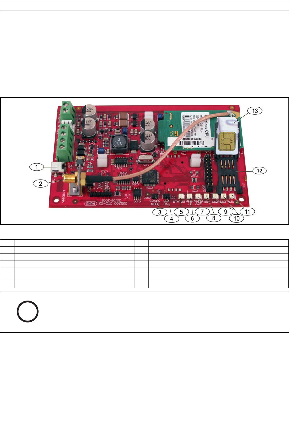
62 en | ITS-DX4020-G Communicator Configuration Easy Series
F01U087835 | 02 | 2008.10 System Reference Guide Bosch Security Systems, Inc.
9 ITS-DX4020-G Communicator Configuration
9.1 ITS-DX4020-G Communicator Overview
The ITS-DX4020-G provides wireless communications between the control panel and the
central monitoring station (CMS). You can configure the ITS-DX4020-G using one of two
methods:
– Short Message Service (SMS)
– Terminal Interface on a PC connected using a USB port
Figure 9.1 ITS-DX4020-G Communicator
1 Mini USB Port 8 Signal Strength 1 (SS1) LED
2 Antenna Connector 9 Signal strength 2 (SS2) LED
3 CONFIG MODE (J200) Jumper Pins 10 Signal strength 2 (SS2) LED
4 LED DIS (J201) Jumper Pins 11 Bus LED
5 STATUS LED 12 SIM Cardholder
6 CELL IP LED 13 SIM Card In Cardholder (Door Open)
7AUDIO ACT LED
i
NOTICE!
To conserve power, install the LED disabling jumper to the LED DIS jumper pins when the
LEDs are not being observed.
When LED DIS jumper pins are shorted for the first time, the STATUS LED flashes the
firmware version.

Easy Series ITS-DX4020-G Communicator Configuration | en 63
Bosch Security Systems, Inc. System Reference Guide F01U087835 | 02 | 2008.10
9.2 Short Message Service (SMS) Configuration
The ITS-DX4020-G supports configuration by SMS. The installer can send the SMS via mobile
phone to the ITS-DX4020-G. To ensure delivery of SMS data, keep each message to a
maximum of 160 characters in length with a maximum of 3 messages. The CONFIG MODE
jumper pins must be shorted together with a plug to allow the receipt of SMS data. Refer to
Table 2.9, Page 26, for LED activity. If the CONFIG MODE jumper pins are not shorted
together, incoming SMS data is discarded. If the shorting plug is removed from the CONFIG
MODE jumper pins before the ITS-DX4020-G receives the complete set of incoming SMS data,
all incoming SMS data is discarded.
When the ITS-DX4020-G receives a complete set of incoming SMS data, it saves the values
and then displays a distinct pattern across the on-board LEDs indicating that the values were
saved (refer to Table 2.9, Page 26 for LED locations). At this time, remove the plug from the
CONFIG jumper pins to restart the ITS-DX4020-G.The ITS-DX4020-G does not send out SMS
data. Table 9.1 shows the typical SMS format. Refer to Table 9.6, Page 69, and Table 9.7,
Page 69, for descriptions of each parameter ID in the SMS format.
Table 9.1 ITS-DX4020-G SMS Format
The configuration SMS string consists of a maximum of three SMS messages. When the ITS-
DX4020-G receives the final valid part of an SMS message, it accepts the configuration. The
communicator waits as long as the CONFIG jumper is on. When the CONFIG jumper is
removed, all incomplete configurations will be deleted.
Table 9.2 shows an example of a single SMS message.
Format Character Description
%SMS sequence number<LF>
<id> = <value><LF>
<id> = <value><LF>
<id> = <value><LF>
!
<LF> If there are multiple SMS messages, the SMS sequence number
indicates the order of the messages and identifies the starting
point for the parameter IDs in each message.
Separate each id/value pair with a line feed (<LF>), carriage return
(<CR>), or semi-colon (;).
To allow spanning of configuration across multiple messages, each
SMS starts with the sequence number followed by the line feed
character.
id=<value> id/value pairs program each parameter on the ITS-DX4020-G.
id/value pairs are not split between multiple SMS parts.
If an SMS message contains id/value pairs with duplicate content,
only the value in the last duplicated pair is used.
! The final part of a single (or multi-) SMS configuration has an
exclamation mark at the end.
i
NOTICE!
To reduce message size, configuration items are designated with numbers, and only the
configuration items that must be changed are sent.

64 en | ITS-DX4020-G Communicator Configuration Easy Series
F01U087835 | 02 | 2008.10 System Reference Guide Bosch Security Systems, Inc.
Table 9.2 Single SMS Example
Table 9.3 and Table 9.4 show an example of a double SMS message split into two parts.
Table 9.3 Double SMS Example, Part 1
Table 9.4 Double SMS Example, Part 2
SMS Line No. Description Sample SMS
%1<LF> SMS sequence number
1=4020G<LF> Current password
2=secret123<LF> New password (case sensitive)
3=123456,4343<LF> PUK and new PIN to set in SIM
10=basic.m2m<LF> APN
11=user@telco.com<LF> GPRS username
12=password<LF> GPRS password
15=1<LF> Enable AES encryption
16=010203040506070809010111213141516<LF> Sample AES key
14=134<LF> Option bus address
! End of configuration
%1
1=4020G
2=secret123
3=123456,4343
10=basic.m2m
11=user@telco.com
12=password
15=1
16=010203040506070809010111213141516
14=134
!
SMS Line No. Description Sample SMS
%1<LF> SMS sequence number
1=4020G<LF> Current password
2=secret123<LF> New password (case sensitive)
3=123456,4343<LF> PUK and new PIN to set in SIM
10=basic.m2m<LF> APN
11=user@telco.com<LF> GPRS username
12=password<LF> GPRS password
15=1<LF> Enable AES encryption
16=010203040506070809010111213141516<LF> Sample AES key
%1
1=4020G
2=secret123
3=123456,4343
10=basic.m2m
11=user@telco.com
12=password
15=1
16=010203040506070809010111213141516
SMS Line No. Description Sample SMS
%2<LF> SMS sequence number
14=134<LF> Option bus address
! End of configuration
%2
14=134
!
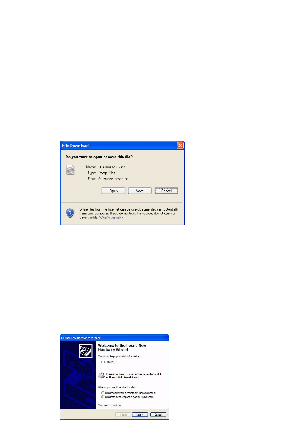
Easy Series ITS-DX4020-G Communicator Configuration | en 65
Bosch Security Systems, Inc. System Reference Guide F01U087835 | 02 | 2008.10
9.3 Accessing the User Interface and Logging On Using USB
9.3.1 Downloading the ITS-DX4020-G USB Driver
Before you can access the USB user interface, you must download and install the ITS-DX4020-
G.inf file on the target PC or laptop. You only need to install this file once on the target PC or
laptop.
1. From your Internet browser, go to http://www.boschsecurity.us/en-us/ to open the US
Bosch web site.
2. Under Online Catalogs, click Intrusion Alarm Systems.
3. Under Download Library, click Software.
4. Under Software, click Intrusion Alarm Systems.
5. Under Intrusion Alarm Systems, click Conettix - Information Transport Solutions.
6. To the right of ITS-DX4020-G.INF, click EN.
The File Download window opens.
Figure 9.2 File Download Window
7. Click Save to save the file to the target PC or laptop.
9.3.2 Installing the ITS-DX4020-G USB Driver
If the target PC or laptop only has one USB port, you only need to install the USB driver once.
If the target PC or laptop has multiple USB ports, you must install the USB driver each time
the ITS-DX4020-G is connected to a new USB port.
1. Ensure that the supplied jumper plug is covering the CONFIG jumpers.
Refer to Figure 9.1, Page 62, Callout 3.
2. Supply power to the ITS-DX4020-G (12 VDC) and connect it to the target PC or laptop,
using a USB-to-mini-USB (5-pin mini-B connector) cable (not supplied).
The Found New Hardware Wizard opens.
Figure 9.3 Found New Hardware Wizard
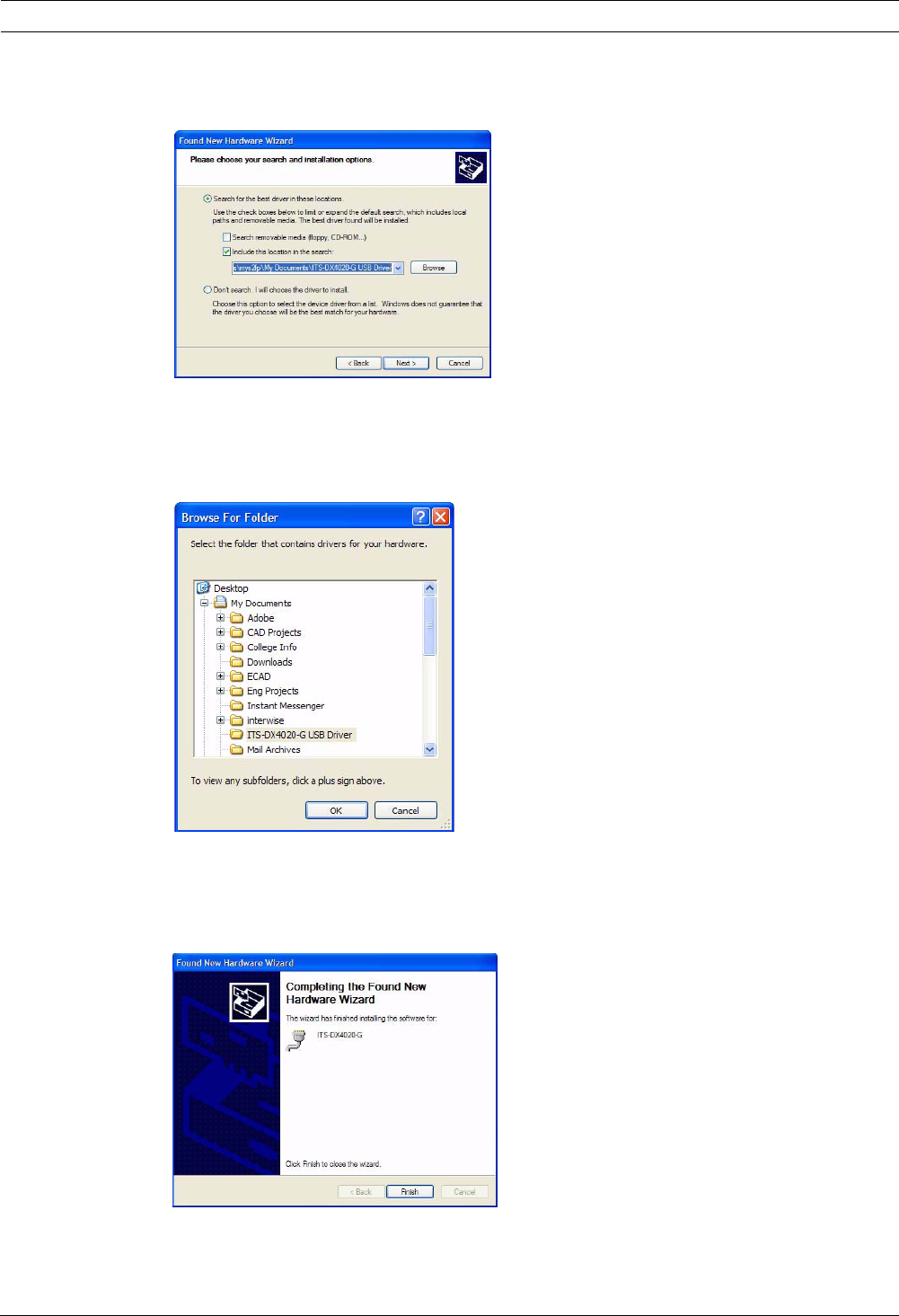
66 en | ITS-DX4020-G Communicator Configuration Easy Series
F01U087835 | 02 | 2008.10 System Reference Guide Bosch Security Systems, Inc.
3. Select Install from a list or specific location (Advanced), and click Next.
The Search and Installation Options window opens.
Figure 9.4 Search and Installation Options Window
4. Under Search for the best driver in these locations, click the Include this location in the
search option, and then click Browse.
The Browse for Folder window opens.
Figure 9.5 Browse For Folder Window
5. In the file directory, go to the location where you saved the ITS-DX4020-G.inf file.
Click OK and then click Next.
The Found New Hardware Finish window opens.
Figure 9.6 Found New Hardware Finish Window
6. Click Finish to complete the installation of the ITS-DX4020-G USB driver.
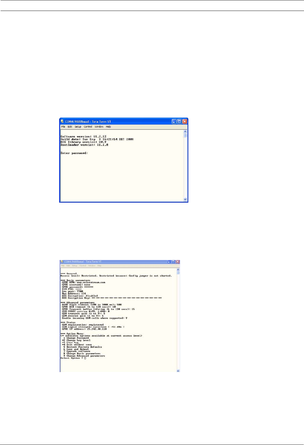
Easy Series ITS-DX4020-G Communicator Configuration | en 67
Bosch Security Systems, Inc. System Reference Guide F01U087835 | 02 | 2008.10
9.3.3 USB Main Menu
1. From Windows, start a terminal session (launch Hyper Terminal if you are running
Windows XP or earlier, or download Tera Term if you are running Windows Vista). Set up
a connection on the new virtual serial COM port using the following settings:
–Bit rate: 9600
–Data bits: 8
–Parity: None
–Stop bits: 1
–Flow control: None
2. Press [Enter].
The ITS-DX4020-G USB login screen opens.
Figure 9.7 ITS-DX4020-G USB Login Screen
3. Enter a valid password to log on. The default password is 4020G (all uppercase).
The user interface allows three attempts to correctly enter the password. After three
failed attempts, you must reset the ITS-DX4020-G by removing the jumper plug from the
CONFIG jumpers.
4. Press [Enter] to continue. The USB main menu opens.
Figure 9.8 ITS-DX4020-G USB Main Menu
The USB main menu appears:
– after successfully entering a password
– every time the user presses [Enter] without first selecting an option from the main
screen
– on returning from a sub-screen

68 en | ITS-DX4020-G Communicator Configuration Easy Series
F01U087835 | 02 | 2008.10 System Reference Guide Bosch Security Systems, Inc.
The main menu shows all current configuration settings first. An asterisk in front of a
configuration item indicates that its setting has been changed during the current session.
The content of the main menu constantly scrolls. When a user performs a new action, any
resulting response from the user interface appears at the end of the menu.
9.3.4 USB Option Menu
Refer to Table 9.5 for a description of the USB option menu items.
To see the USB option menu, refer to Figure 9.8, Page 67.
Table 9.5 ITS-DX4020-G Menu Options
At a configuration screen, items are presented one at a time with the current value inside [ ]
brackets. If you press [Enter] without entering a new value, the current value is unchanged.
To go to a specific menu option, enter the appropriate menu item number and press [Enter].
Option Press to
Select
Description
1 Change password 1 To change the login password, enter the old password first, and then
enter the new password twice. The second entry is to confirm the new
password.
Passwords must be 4-15 characters long, and they are case-sensitive.
0-9, A-Z, a-z, and special characters are allowed.
2 Change log level 2 Change the debugging level shown on the View Log screen.
3 View log 3 View the debugging log. Press any key to exit.
4 Exit without Save 4 Return to the user interface login screen. All configuration changes that
were made are lost and are replaced with the default values.
5 Restore Factory defaults 5 Select Yes to restore all factory default configurations.
When prompted, remove the plug from the CONFIG jumper pins to
restart the ITS-DX4020-G.
6 Save and Reboot 6 Select Yes to save all configuration changes.
When prompted, remove the plug from the CONFIG jumper pins to
restart the ITS-DX4020-G.
7 Upgrade Software 7 Select this option to upgrade the software in the ITS-DX4020-G.
Refer to Section 9.4 Upgrading the ITS-DX4020-G Software, page 70.
8 Change Basic parameters 8 To change a basic parameter:
1. Select the parameter.
2. Enter the desired value and press [Enter].
Refer to Table 9.6, Page 69 for basic parameters.
9 Change Advanced parameters 9 Select to change advanced parameters.
Refer to Table 9.7, Page 69 for advanced parameters.

Easy Series ITS-DX4020-G Communicator Configuration | en 69
Bosch Security Systems, Inc. System Reference Guide F01U087835 | 02 | 2008.10
Table 9.6 ITS-DX4020-G Basic Parameters
Table 9.7 ITS-DX4020-G Advanced Parameters
ID Parameter Default Values Description
1 Current Password 4020G 4 to 15 characters Mandatory and case sensitive.
2 New Password none 4 to 15 characters New password, as desired. Case sensitive
3 SIM PUK,PIN none Maximum 10 numeric
digits each
Sets the PIN into the SIM and the ITS-
DX4020-G
4 SIM PIN No PIN 4 numeric digits Sets the PIN in the ITS-DX4020-G.
10 GPRS APN <blank> 1 to 63 characters Access point name.
11 GPRS username none 1 to 63 characters Username for wireless service provider
(not always required).
12 GPRS password none 1 to 63 characters Password for wireless service provider (not
always required).
13 Src port 7700 1 to 65535 characters Sets the port for the ITS-DX4020-G.
14 Bus Address 134 SDI: 80, 88
Option Bus: 134
Sets the option bus address for
communication with the control panel. For
Easy Series, use Address 134.
15 AES Encryption 0 0 = Disabled
1 = Enabled
Security encryption on/off; must match
encryption settings in the receiver.
16 AES Encryption Key <blank> 32 characters max.
0-9, A-F, a-f allowed
Key must match encryption key in the
receiver.
ID Parameter Default Values Description
50 DTMF digit timeout 500 100 to 3000 ms Acceptable time between dialled DTMF
digits from the panel.
51 GPRS ACK timeout 10 6 to 120 secs GPRS restarts if there is no response by
the entered time.
52 GPRS Transmit buffer
lifetime
15 6 to 120 secs Duration the panel messages are buffered
in the communicator before being
discarded.
53 GSM CODEC setting 0 0 = Full Rate (FR)
1 = Adaptive Multi-rate
(AMR)
Set to Full Rate when GSM is being used.
54 GSM transmit gain 5 0 to 10 Gain on transmitted GSM signals
55 GSM receive gain 5 0 to 10 Gain on received GSM signals.
56 Enable incoming GSM
calls where supported
1 0 = Disabled
1 = Enabled
Enables/Disables incoming GSM calls.
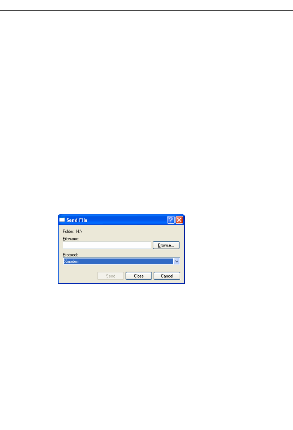
70 en | ITS-DX4020-G Communicator Configuration Easy Series
F01U087835 | 02 | 2008.10 System Reference Guide Bosch Security Systems, Inc.
9.4 Upgrading the ITS-DX4020-G Software
To upgrade the software in the ITS-DX4020-G, you must download the latest ITS-DX4020-G
binary file from the Bosch website to the target PC or laptop, and then use either Hyper
Terminal or Tera Term to install the binary file on the ITS-DX4020-G.
9.4.1 Downloading the Latest Software
1. From your Internet browser, go to http://www.boschsecurity.us/en-us/ to open the US
Bosch web site.
2. Under Online Catalogs, click Intrusion Alarm Systems.
3. Under Download Library, click Software.
4. Under Software, click Intrusion Alarm Systems.
5. Under Intrusion Alarm Systems, click Conettix - Information Transport Solutions.
6. To the right of ITS-DX4020-G_x.x.x.bin, click EN.
The File Download window opens.
7. Click Save to save the file to the target PC or laptop.
9.4.2 Installing the Software with Hyper Terminal
Microsoft® includes Hyper Terminal with the Windows XP® operating system, and earlier
operating systems.
1. In Windows, click Start→All Programs →Accessories →Communications →Hyper
Terminal.
2. From the Hyper Terminal menu, click Transfer→Send File.
The Send File window opens.
Figure 9.9 Hyper Terminal Send File Window
3. Click Browse and go to the location where you downloaded the ITS-DX4020-G binary file.
4. In Protocol, select Xmodem.
5. Click Send to start the software upgrade.
6. When the software upgrade is complete, close Hyper Terminal, and remove the jumper
plug from the CONFIG jumpers on the ITS-DX4020-G. The ITS-DX4020-G restarts.
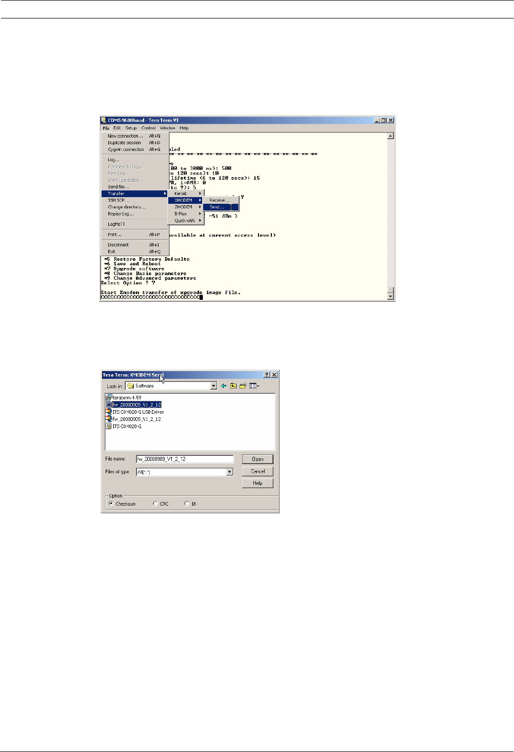
Easy Series ITS-DX4020-G Communicator Configuration | en 71
Bosch Security Systems, Inc. System Reference Guide F01U087835 | 02 | 2008.10
9.4.3 Installing the Software with Tera Term
If you are using Microsoft® Vista®, you must download and install a communication utility,
such as Tera Term, on the target PC or laptop.
1. Start Tera Term.
2. Select File→Transfer→XMODEM→Send.
Figure 9.10 Tera Term File Menu Path
3. In the XMODEM Send window, use the Look in: menu to find the location where you
downloaded the ITS-DX4020-G binary file.
4. Click Open to start the software upgrade.
Figure 9.11 Tera Term XMODEM Send Window
5. When the software upgrade is complete, close Tera Term, and remove the jumper plug
from the CONFIG jumpers on the ITS-DX4020-G. The ITS-DX4020-G restarts.

72 en | Device Specifications and Overview Easy Series
F01U087835 | 02 | 2008.10 System Reference Guide Bosch Security Systems, Inc.
10 Device Specifications and Overview
10.1 Control Panel
Enclosure
Dimensions (H x W x D): 37 cm x 31.8 cm x 8.5 cm (14.5 in x 12.5 in x 3.25 in)
Construction Material: Cold-rolled steel, zinc seal, 0.36 mm thick (20 Ga.)
Environmental Considerations
Relative Humidity: 93% at 32°C 2°C (89.6°F 35.6°F)
Operating Temperature: -10°C to +49°C (14°F to +120°F)
CE: -10°C to +40°C (+14°F to +104°F)
NF A2P: -10°C +55°C (+14°F to +131°F)
Storage Temperature: -10°C to +55°C (+14°F to +131°F)
Protection Level IP 30 - IK 04
Supervised Points
On-board Hardwire: 8
Single or dual end-of-line (2.2 k EOL) tamper point support
Point 1 supports two-wire smoke detectors
All points support four-wire smoke detectors
Enclosure tamper input (does not reduce point capacity)
Reaction time lower than 250ms
Programmable Outputs (PO)
On-board: 4
PO 1 only: Configurable relay
PO 2 to PO 4: Configurable solid state
PO 4 only: Internal supervised speaker driver option
PO 1 Relay Rating: Contacts: 2 A with no jumper installed; resistive loads only; in a NF A2P
certified installation: 1 A
Output: 1.2 A with jumper installed; resistive loads only; in a NF A2P
certified installation 1 A
Operating Voltage: 30 VDC maximum
PO 2 to PO 4 Rating: 400 mA current sink
Number of...
Users: 22
User 1: Master user
Users 2 to 21: System users
User 22: Duress user
Events: 500 history events, stamped with time and date
Tokens and Key Fobs: One per user (User 22 does not receive a token or key fob)
Phone Line
Phone line trouble voltage Trouble condition occurs when the phone line voltage is between 1.10 V
and 4.75 V
Control Panel Power Requirements

Easy Series Device Specifications and Overview | en 73
Bosch Security Systems, Inc. System Reference Guide F01U087835 | 02 | 2008.10
AC Input Line Voltage Use a UL Listed 18 V Class 2 transformer (22 VAC, VA 50/60 Hz), or the
EZPS Power Supply
In an NF A2P certified installation, use the EZPS power supply delivered
with the panel
Total Alarm Power: 1.4 A (AC power and standby battery; intrusion applications only).
With a 7.0 Ah battery, the following current draws apply to all outputs and
devices connected to the system:
– Up to 170 mA for 24 hr for fire and combined fire/burglary
applications
– Up to 1.2 A for other applications
Auxiliary Power: 12 VDC, 1.0 A maximum. Includes 110 mA for each control center
connected to the system, and up to 400 mA for the programmable outputs.
Current Draw: 85 mA standby; 160 mA alarm with all outputs activated
Voltage: 12 VDC nominal (11.2 VDC to 12.3 VDC)
The control panel stops processing point faults when the voltage drops
below 9.5 VDC.
Battery: D126 (7 Ah) or D1218 (18 Ah) sealed, lead acid rechargeable
1.7 A maximum recharging current
Low battery condition occurs when battery drops below 12 VDC
If AC power fails and the battery drops below 9.5 VDC, the control panel
stops processing point faults. Disconnect the battery under these
conditions.
Maximum auxiliary current to recharge standby battery within 72 hours:
–12 V, 7 Ah Battery: 400 mA
–12 V, 18 Ah Battery: 900 mA
In an NF A2P certified installation, use a battery Yuasa NP17-12IFR
EZPS Power Supply Requirements
AC Input: AC Input Voltage: 100 VAC to 240 VAC
Line Voltage Frequency: 47 Hz to 63 Hz
Maximum Input Current: 0.5 A
Power Factor: Approximately 0.65 at full load
DC Output: Nominal Output Voltage under AC line input: 18 VDC
Output Voltage Range under AC line input: 16 VDC to 20 VDC
Continuous Rated Output Current: 1.25 A
Output Current Limit: Approximately 1.75 A to 2.5 A
Periodic and Random Deviation (PARD): Less than 250 mV

74 en | Device Specifications and Overview Easy Series
F01U087835 | 02 | 2008.10 System Reference Guide Bosch Security Systems, Inc.
10.1.1 Standby Battery Calculation
Use the following formula to calculate standby battery capacity for 24 hr of standby power:
(Total B _____ x 24 hr) + (Total C _____ x 0.067 hr) + 10% reserve = Total battery Ah required
If the Column C total exceeds 1.4 A, use an external power supply.
A
AC Power On Normal
Current
B
AC Power Off Minimum
Current
C
In Alarm Maximum Current
Model Qty
Used
Each Unit
(mA)
Total
(mA)
Each Unit
(mA)
Total
(mA)
Each Unit
(mA)
Total
(mA)
Control Panel 85 x1 85 85 x1 85 160 x1 160
Control
Center
110 x Qty 110 xQty 165 xQty
Wireless Hub
(IWT-WSN-N!-
86)
30x Qty 30x Qty 30xQty
DX2010 35 x Qty 35 x Qty 0 35 xQty
Sounders Connected to PO 4
D118 8 Ω
Speaker
0 xQty 0 0 xQty 0 330 xQty
Ratings of other devices in system that are not shown above
x Qty x Qty x Qty
x Qty x Qty x Qty
x Qty x Qty x Qty
x Qty x Qty x Qty
x Qty x Qty x Qty
Total
A
Total
B
Total
C
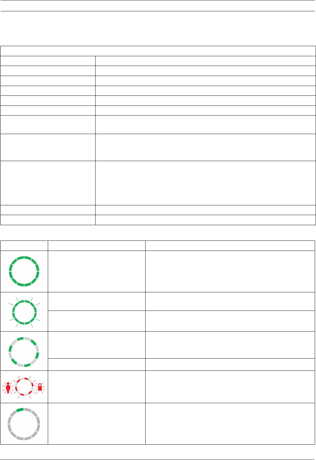
Easy Series Device Specifications and Overview | en 75
Bosch Security Systems, Inc. System Reference Guide F01U087835 | 02 | 2008.10
10.2 Control Center
Control Center Specifications
Control Center Display States
Control Center
Dimensions (H x W x D): 12 cm x 17.7 cm x 2.5 cm (4.7 in. x 7 in. x 1 in.)
Total Number Supported: 4
Recommended Mounting Surface: Non-metallic surface
Minimum Mounting Distance: 1.2 m (4 ft) between each control center
Current Draw: 110 mA standby; 165 mA alarm
Minimum Wire Length: 3 m (10 ft)
Maximum Wire Length: Total: 400 m (1312 ft) using 0.8 mm (22 AWG) wire;
Single run: 100 m (328 ft) using 0.8 mm (22 AWG) wire
Data Bus Wire Type Options: 1 four-conductor, power-limited 1.2 mm (18 AWG) or 0.8 mm (22 AWG) wire
At least 0.6 mm (24 AWG) twisted pair CAT5 wire.
UL installations require power-limited wiring.
Audio Bus Wire Type Options: 1 two-conductor or 1 four-conductor, power-limited 1.2 mm (18 AWG) or 0.8
mm (22 AWG) wire. Only two conductors are used.
At least 0.6 mm (24 AWG) twisted pair CAT5 wire.
UL installations require power-limited wiring.
Unless using CAT5 cable, audio bus connections require a dedicated wire.
CAT5 Wire Requirements: Refer to Section 2.2.3 Install the Control Center, page 14.
Protection Level IP 30 - IK 04
Display Color Description
Green circle No alarm or trouble conditions exist.
You can turn on the system.
Flashing green circle System trouble exists. You can still turn on the system.
Alarm memory active.
Flashing amber circle System trouble exists. You cannot turn on the system.
Alarm memory active.
Broken green circle Wired point(s) are faulted. Turn on the system to bypass
faulted point(s).
Chime point faulted. Chime tone sounds.
Broken amber circle Wired point(s) are faulted. You cannot turn on the system.
Broken red circle;
flashing red icons
Fire or intrusion alarm occurred.
Single rotating segment Alarm memory announcement. Add or change user token.
Waiting for information from wireless network.
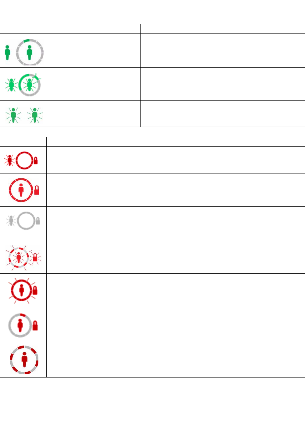
76 en | Device Specifications and Overview Easy Series
F01U087835 | 02 | 2008.10 System Reference Guide Bosch Security Systems, Inc.
Table 10.1 System Off Display States
Table 10.2 System On (Occupied or Custom Protection) Display States
Green circle and icons Add or change user passcode. Outside icon appears for first
passcode entry.
Inside icon appears for second passcode entry.
Green or amber Point walk test.
Green single circle segments represent tested points.
Green flashing icons Control center test. Icons alternately flash.
Display Color Description
Display Color Description
Flashing red icon Exit Delay in progress. Circle segments turn on, one at a
time, to provide a visual status of Exit Delay.
Red System is on (occupied or custom protection).
Flashing icon
(amber then red)
Entry Delay in progress.Circle segments turn off, one at a
time, to provide a visual status of Entry Delay.
Amber icon: First half of Entry Delay.
Red icon: Second half of Entry Delay.
Broken red circle;
flashing red icons
Fire or intrusion alarm occurred.
Flashing red circle Active alarm memory (if system is on).
System trouble exists.
Single red rotating segment Alarm memory announcement (if system is on).
Broken red circle At least one point is faulted or bypassed; no trouble exists.
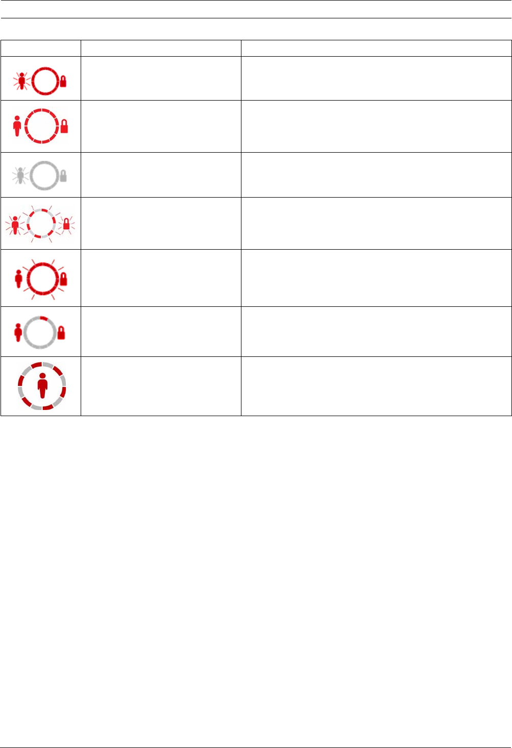
Easy Series Device Specifications and Overview | en 77
Bosch Security Systems, Inc. System Reference Guide F01U087835 | 02 | 2008.10
Table 10.3 System On (Unoccupied) Display States
Display Color Description
Flashing red icon Exit Delay in progress.
Red System is on (unoccupied).
Flashing icon
(amber then red)
Entry Delay in progress.
Amber icon: First half of Entry Delay.
Red icon: Second half of Entry Delay.
Broken red circle;
flashing red icons
Fire or intrusion alarm occurred.
Flashing red circle Active alarm memory (if system is on).
Single red rotating segment Alarm memory announcement (if system is on).
Broken red circle At least one point is faulted or bypassed; no trouble exists.

78 en | Device Specifications and Overview Easy Series
F01U087835 | 02 | 2008.10 System Reference Guide Bosch Security Systems, Inc.
10.3 DX2010 Input Expander
The DX2010 Input Expander connects directly to the data bus of a compatible control panel.
Each expander adds eight input loops.
Add a DX2010 Before Adding Wireless Points
The control panel supports up to three DX2010 modules. Each module occupies a group of
eight points.
The DX2010's DIP switch address determines which group of points the DX2010 occupies:
– Address 102: DX2010 occupies Points 9 to 16
– Address 103: DX2010 occupies Points 17 to 24
– Address 104: DX2010 occupies Points 25 to 32
Refer to on Section 2.2.6 Install the DX2010 Input Expander, page 16, for more DIP switch
settings.
As each DX2010 module is added to the system, it occupies the next available group of points.
For Points 9 to 32, wireless points also occupy points in the same groups of eight as the
DX2010 modules:
– If you add two DX2010 modules using Addresses 102 (Points 9 to 16) and 103 (Points 17
to 24), wireless points can only occupy Points 25 to 32.
– If you add three DX2010 modules, wireless points can only occupy Points 1 to 8.
– If you add a DX2010 module using address 102 (Points 9 to 16), wireless points can only
occupy Points 17 to 32.
i
NOTICE!
If Points 9 to 32 contain wired and wireless points, install all required DX2010 Input
Expanders before adding any wireless points to the system.
DX2010 Input Expander
Operating Voltage: 8 VDC to 14 VDC
Current Draw: 35 mA standby; 135 mA maximum with connected accessories
Outputs: 100 mA, 12 VDC supervised output for accessories
Sensor Loop Terminal Wire Size: 0.8 mm (22 AWG) to 1.8 mm (14 AWG)
Wire Length: Control panel to DX2010 (DX2010 auxiliary output not used):
– 0.8 mm (22 AWG) = 305 m (1000 ft)
– 1.2 mm (1.2 mm) = 610 m (2000 ft)
Control panel to DX2010 (DX2010 auxiliary output supplying 100 mA):
– 0.8 mm (22 AWG) = 30 m (100 ft)
– 1.2 mm (1.2 mm) = 76 m (250 ft)
Operating Temperature: 0°C to +50°C (+32°F to +122°F)
Relative Humidity: 5% to 85% at +30°C (+86°F)
Sensor Loop Resistance: 60 Ω maximum
Sensor Loop: Up to eight inputs; input contacts can be normally open (NO) or normally closed
(NC) with appropriate EOL resistors for supervision.

Easy Series Device Specifications and Overview | en 79
Bosch Security Systems, Inc. System Reference Guide F01U087835 | 02 | 2008.10
Add a DX2010 After Adding Wireless Points
If you add a DX2010 module after wireless points are added, based on its DIP switch address,
the DX2010 replaces the conflicting group of wireless points.
For example, if wireless points occupy Points 9 to 24, and you need Points 17 to 24 as wired
points, a DX2010 module with Address 103 replaces the wired points occupying Points 17 to
24.
If the next point grouping is available, for this example, Points 25 to 32, the control panel
retains all point programming except for voice descriptions, and moves the conflicting
wireless points to the next point grouping. You must re-record voice descriptions for the
points that were moved.
If the next point grouping is not available, the control panel deletes the conflicting wireless
points from the system.
10.4 Conettix DX4020 Network Interface Module
The Conettix DX4020 Ethernet Network Interface Module creates two-way communications
over Ethernet networks for compatible control panels.
10.5 ITS-DX4020-G Communicator
The Conettix ITS-DX4020-G Communicator is a multi-function, dual-path security
communicator that communicates with Bosch Security Systems, Inc. Conettix receivers. It is
compatible with DX4020 protocols, and it provides a cellular (GSM/GPRS) modem.
DX4020 Network Interface Module
Operating Voltage: 12 VDC nominal
Current Draw: 10Base-T: 110 mA maximum; 100Base-T: 135 mA maximum
Operating Temperature: 0°C to +50°C (+32°F to +122°F)
Relative Humidity: 5% to 85% at +30°C (+86°F)
ITS-DX4020-G GPRS/GSM Communicator
Operating Voltage: 12 VDC nominal, 10 VDC to 15 VDC
Current Draw: Standby: 70mA, Alarm: 400mA
Operating Temperature: -10°C to +55°C (+14°F to +131°F)
Relative Humidity: 5% to 95%
Ripple/Noise: 200 mVpp maximum
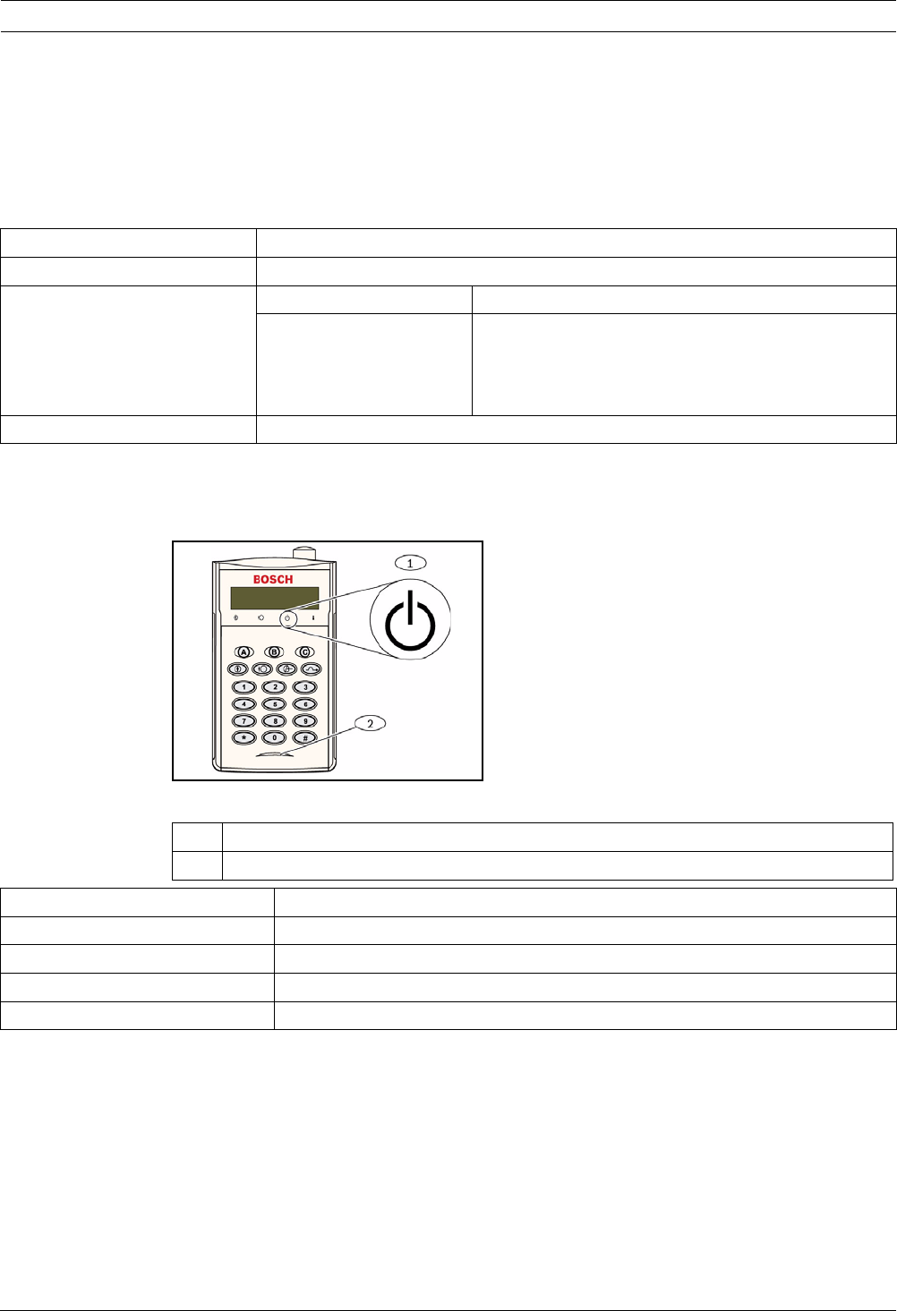
80 en | Device Specifications and Overview Easy Series
F01U087835 | 02 | 2008.10 System Reference Guide Bosch Security Systems, Inc.
10.6 wLSN Installation Tool
Use the wLSN Installation Tool to determine the best locations for wLSN device installation.
The Installation Tool communicates signal strength and packet success ratios through an LCD
display.
Specifications
LED Displays
The crescent-shaped LED indicates charging status when placed in a docking station.
Refer to Figure 10.1 on Page 80 and Table 10.4 on Page 80.
Figure 10.1 wLSN Installation Tool
Table 10.4 wLSN Installation Tool LED Status
868 MHz ISW-BIT1-HAX, ISW-BIT1-HBX, ISW-BIT1-HCX
915 MHz ISW-BIT1-HCX
Power Docked 12 VDC nominal, 6 VDC to 14 VDC
Batteries 3 AAA NiMH rechargeable batteries that require an
initial charge of at least 7 hours of charging.
Operating Life: Up to 50 hours of continuous use on a
single charge.
EN50131-1 Environmental Class II
1 Power Indicator
2 Charging Status LED
LED (Green) Status
On Batteries fully charged
Off Installation Tool operation on battery only.
Flashing Batteries charging
Flashing power indicator Low battery

Easy Series Device Specifications and Overview | en 81
Bosch Security Systems, Inc. System Reference Guide F01U087835 | 02 | 2008.10
10.7 wLSN Hub
Specifications
The wLSN Hub monitors and coordinates two-way communications between the control panel
and the detectors.
Rotary switches (S1, S2, and S3) configure device operation and enable special diagnostic
modes.
An LED on the front provides device status.
General Operation
Refer to Table 10.5 on Page 81 and Table 10.6 on Page 81 for an overview on wLSN Hub LEDs
and switch settings.
Table 10.5 wLSN Hub LED Displays
Table 10.6 wLSN Hub Switch Settings
868 MHz ISW-BHB1-WX
915 MHz ISW-BHB1-WY
Wire Gauge 0.14 mm to 1.5 mm
Wire Length 100 m
Power/Voltage 12 VDC nominal, 7 to 14 VDC
Current Draw 60 mA maximum
Compliance EN50131-1 Security Grade 2 Type C, Environmental Class II
Operation LED Display
Self Test and Hardware Failure LED flashes twice per sec. This indicates failure. The wLSN Hub does
not operate.
Standard Operation LED on.
Configuring Network LED flashes once every 2 sec.
RFSS Mode LED flashes once every 4 sec.
Switches
Function S1 S2 S3
Normal Operation 1 0 0
RFSS Mode 9 2 0
Default Mode987

82 en | Device Specifications and Overview Easy Series
F01U087835 | 02 | 2008.10 System Reference Guide Bosch Security Systems, Inc.
10.8 wLSN PIR and Dual Motion Detectors
The PIR Motion Detector (ISW-BPR1-W13PX) uses an infrared sensor. The Dual Motion
Detector uses (ISW-BPR1-W13PGX) both PIR and microwave technology.
A cover-and-wall tamper switch transmits a tamper signal when the cover is removed from its
base, or when the unit is pulled away from the wall.
An LED provides status for Walk Test, RFSS, and Discovery Modes.
Specifications
Sensitivity Settings
Sensitivity settings are set at the control panel. Refer to the control panel's documentation for
detailed information.
1. Standard Sensitivity
Use this setting when pets are present in the area to be monitored. Standard sensitivity
provides excellent detection performance and is the least sensitive to false alarms.
2. Intermediate Sensitivity
Only use this setting in non-pet installations where environmental disturbances are
minimal. Intermediate sensitivity provides the highest level of detection performance.
3. Setting the Dual Motion Detector's Microwave Range Adjustment
a. If the microwave coverage needs adjustment (red or yellow LED does not light),
increase or decrease the microwave range as needed (using the back of the device).
b. Repeat the Walk Test.
c. Repeat Steps a and b until the required coverage is met.
868 MHz PIR: ISW-BPR1-W13PX
Dual: ISW-BDL1-W11PGX, ISW-BDL1-W11PHX, ISW-BDL1-W11PKX
915 MHz PIR: ISW-BPR1-W13PY
Dual: ISW-BDL1-W11PGY, ISW-BDL1-W11PHY, ISW-BDL1-W11PKY
PIR Motion Detector Power/
Voltage
Four AA 1.5 V alkaline batteries
Dual Motion Detector Power/
Voltage
Six AA 1.5 V alkaline batteries
EN50131-1 Security Grade 2, Environmental Class II
i
NOTICE!
The Dual Motion Detector's microwave motion sensor is factory adjusted to sense motion to
at least 11 m.

Easy Series Device Specifications and Overview | en 83
Bosch Security Systems, Inc. System Reference Guide F01U087835 | 02 | 2008.10
10.9 wLSN Door-Window Contact
The wLSN Door-Window Contact is a magnetic reed switch and wireless transceiver used for
monitoring doors, windows, and other dry contact devices.
A cover-and-wall tamper switch transmits a tamper signal when the cover is removed from its
base, or when the unit is pulled away from the wall.
An LED provides status for RFSS and Discovery Modes.
Specifications
Supported Wiring Configurations
The wLSN Door-Window Contact provides a supervised point for monitoring external devices.
Refer to Section 2.2.7 Connect Supervised Points on page 19 for supported wiring options
when using the supervised point.
10.10 wLSN Recessed Door-Window Contact
The wLSN Recessed Door-Window Contact is a wireless transceiver used for monitoring doors
A cover tamper switch transmits a tamper signal when the cover is removed from its base.and
windows.
An LED provides status for RFSS and Discovery Modes.
Specifications
868 MHz ISW-BMC1-S135X
915 MHz ISW-BMC1-S135Y
Maximum Distance Between Sensor and
Magnet
<12,7 mm, the magnet can be placed on either side.
The base is marked to indicate the magnet position.
Wire Gauge 0.14 mm (22 AWG) to 1.5 mm (16 AWG)
Power/Voltage Two AA batteries, 1.5 V alkaline
Terminal Block For connecting other dry contact devices such as another magnetic reed
switch. (2.2k EOL)
EN50131-1 Security Grade 2, Environmental Class II
i
NOTICE!
Mounting the wLSN Recessed Door-Window Contact in a metal door or window frame could
degrade the RF signal strength.
868 MHz ISW-BMC1-R135X
915 MHz ISW-BMC1-R135Y
Power/Voltage One CR2 lithium battery, 3 VDC
Maximum Distance Between Reed
Switch and Magnet
<12,7 mm
Drill Tools Requires the use of a 19 mm (3/4 in.) drill bit and 22 mm
(7/8 in.) spade bit
Circuit Board Removal Needle nose pliers are recommended
EN50131-1 Security Grade 2, Environmental Class II
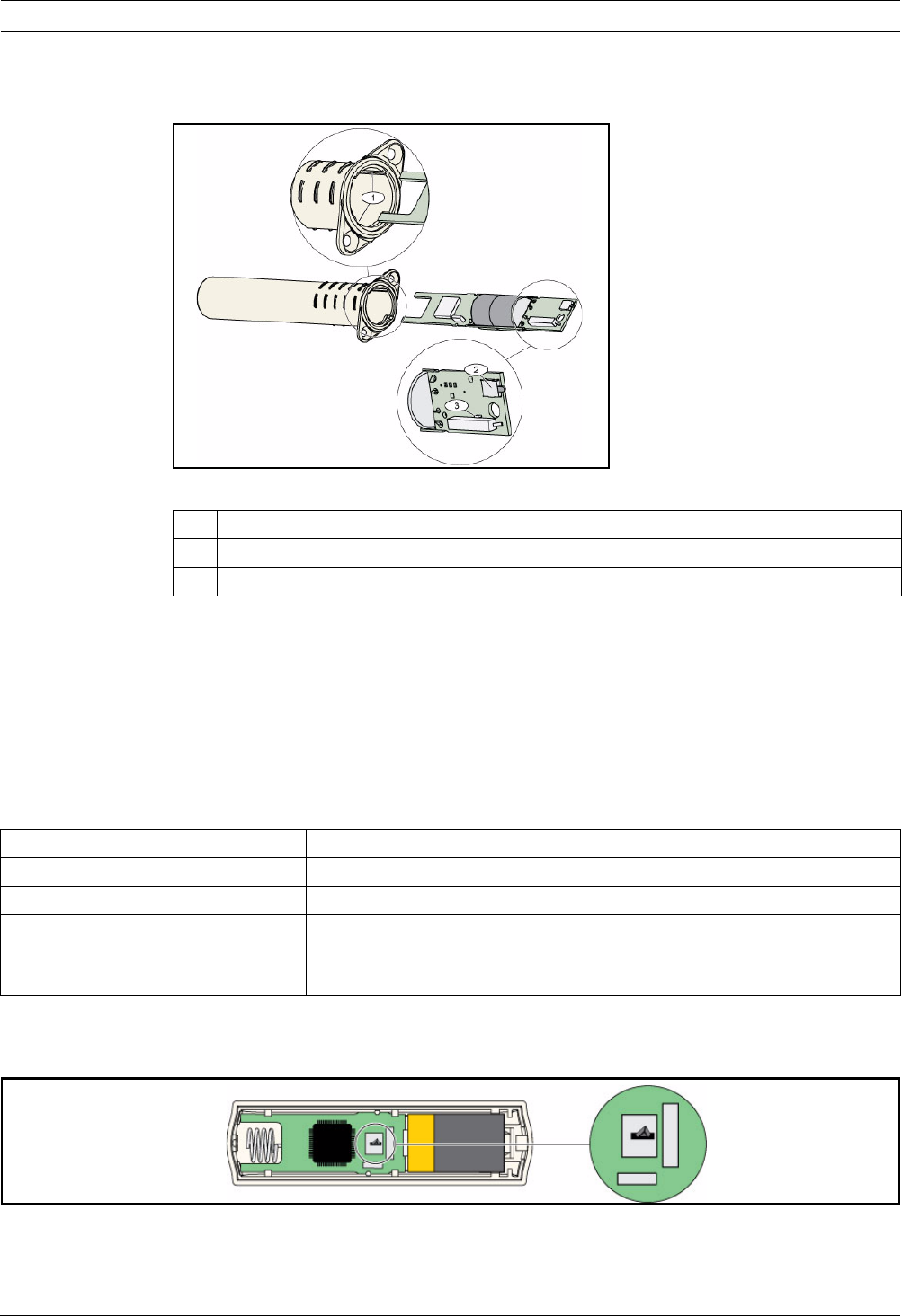
84 en | Device Specifications and Overview Easy Series
F01U087835 | 02 | 2008.10 System Reference Guide Bosch Security Systems, Inc.
Tamper Switch Location
Refer to Figure 10.2 on Page 84 for the location of the device's tamper switch and LED.
Figure 10.2 Recessed Door-Window Contact
10.11 wLSN Mini Door-Window Contact
Similar to the wLSN Door-Window Contact, the wLSN Mini Door-Window Contact is a wireless
transceiver device used for monitoring doors and windows.
A cover-and-wall tamper switch transmits a tamper signal when the cover is removed from its
base, or when the unit is pulled away from the wall.
An LED provides status for RFSS, and Discovery Modes.
Specifications
Tamper Switch Location
Refer to Figure 10.3 on Page 84 for the location of the device's tamper switch.
Figure 10.3 Mini Door-Window Contact Tamper Switch
1 Mounting slots for printed circuit board
2Tamper switch
3 LED for RFSS Mode and Discovery Mode
868 MHz ISW-BMC1-M82X
915 MHz ISW-BMC1-M82Y
Power/Voltage One CR2 lithium battery, 3 VDC
Maximum Distance Between Reed
Switch and Magnet
<12,7 mm (1/2 in.)
The magnet can be placed on either side of the detector.
EN50131-1 Security Grade 2, Environmental Class II
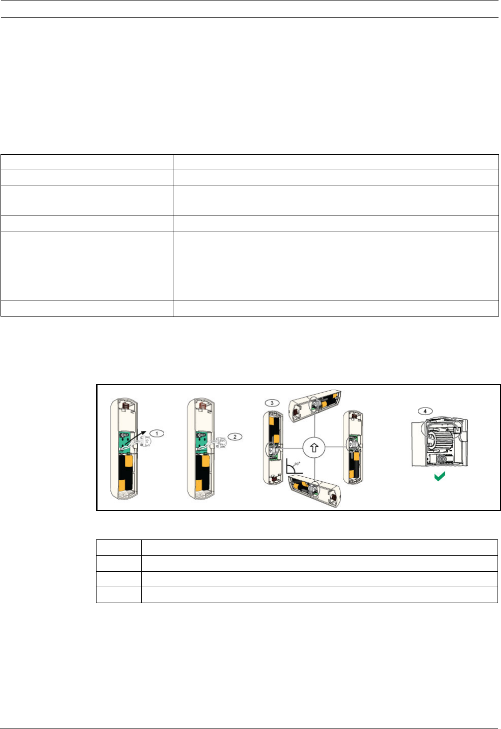
Easy Series Device Specifications and Overview | en 85
Bosch Security Systems, Inc. System Reference Guide F01U087835 | 02 | 2008.10
10.12 wLSN Inertia Detector
The wLSN Inertia Detector is a vibration detector combined with a wireless transceiver used
for monitoring doors or windows.
A cover-and-wall tamper switch transmits a tamper signal when the cover is removed from its
base, or when the unit is pulled away from the wall.
An LED provides status for Test, RFSS, and Discovery Modes.
Specifications
Sensor Adjustment
Proper sensor element orientation is critical to the operation of the device. The arrow,
embossed on the body of this sensor, must always point up. Refer to Figure 10.4 on Page 85
for arrow and for proper wire routing when reinserting the sensor element.
Figure 10.4 Sensor Adjustment
868 MHz ISW-BIN1-S135X
915 MHz ISW-BIN1-S135Y
Maximum Distance Between Detector
and Magnet
<12,7 mm (1/2 in.)
The magnet can be placed on either side of the detector.
Power/Voltage 2 AA batteries, 1.5 V alkaline
Sensor Adjustment Adjust the position of the sensor element, so the arrow always points up by
removing and replacing the element to accommodate the possible
placement positions (refer to Figure 10.4 on Page 85).
Route the wiring from the sensor element so it does not make contact with
the tamper spring (refer to Figure 10.4 on Page 85).
EN50131-1 Security Grade 2, Environmental Class II
1 Remove sensor element
2 Turn sensor element as desired
3 Ensure arrow on sensor element points up
4 Proper wire routing

86 en | Device Specifications and Overview Easy Series
F01U087835 | 02 | 2008.10 System Reference Guide Bosch Security Systems, Inc.
Sensitivity Settings
All sensitivity settings are programmed at the control panel (refer to Section 5.2.6 Point
Programming Items, page 52). The sensor element has two settings:
– Gross Attack
– Minor Attack
Gross Attack is always enabled. The Minor Attack setting is very sensitive and can be disabled.
Test Mode
The unit is automatically in Test mode for the first 10 minutes after power up.
The green LED flashes:
– Once to indicate initialization is complete and the unit is in Test mode
– Twice to indicate a Minor Attack test
– Three times to indicate a Gross Attack test
i
NOTICE!
A single tap such as a branch in the wind lightly brushing a window can start the minor attack
timer and tap count. To avoid false alarms, do not use the Minor Attack setting where there is
potential for stray vibrations.
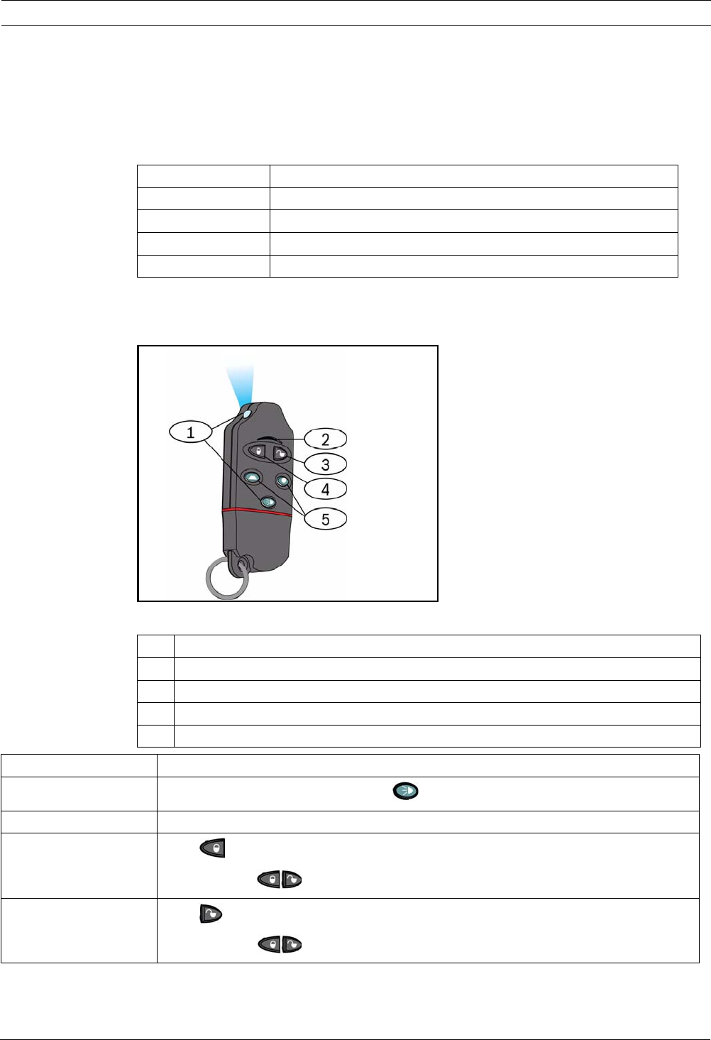
Easy Series Device Specifications and Overview | en 87
Bosch Security Systems, Inc. System Reference Guide F01U087835 | 02 | 2008.10
10.13 wLSN Key Fob
The wLSN Key Fob is a two-way personal transmitter carried by the user. Use it to remotely
arm or disarm a security area.
Specifications
Key Fob User Interface
Refer to Figure 10.5 on Page 87, Table 10.7 on Page 88, and Table 10.8 on Page 88 for key fob
LED and button functions.
Figure 10.5 wLSN Key Fob Button and LED Locations
868 MHz ISW-BKF1-H5X
915 MHz ISW-BKF1-H5Y
Power/Voltage Two CR2032 lithium batteries, 3 VDC
Gaskets Interchangeable; for multiple users, different colors available
EN50131-1 Security Grade 2, Environmental Class II
1 High intensity LED
2 Status LED
3 Disarm button
4 Arm button
5 Programmable buttons
LED/Button Function
High intensity LED Suitable for use as a flashlight. Press to operate.
Status LED Refer to Table 10.8 on Page 88 for status indications.
Disarm button Press to turn the system off.
Press and hold for 1 sec to create a panic alarm.
Arm button Press to turn the system on (unoccupied).
Press and hold to create a panic alarm.
88 en | Device Specifications and Overview Easy Series
F01U087835 | 02 | 2008.10 System Reference Guide Bosch Security Systems, Inc.
Table 10.7 wLSN Key Fob LEDs and Buttons
Table 10.8 wLSN Key Fob LED Status
Programmable buttons To operate the programmable buttons, press and hold or for at least one sec.
Program these buttons at the control panel to control lights, garage doors, and so on.
Refer to Expert Programming Items 616 and 626 on page 56.
High intensity LED
button
Press [FIG] to operate the high intensity LED.
LED/Button Function
Status Description
Alternating red and green A key fob button was pressed. The LED either stops flashing, or one of the other status
indicators in this table occurs. This display lasts approximately for 15 sec.
Red fast flash The system is in alarm, or silent panic feature was used.
Red slow flash Exit delay in progress (system occupied or unoccupied).
Red on steady The system is on (occupied or unoccupied).
Green fast flash An error occurs while turning the system on. The system does not turn on as expected.
Green slow flash The system is not ready to turn on. A button programmed for system status also shows
this status.
Green on steady The system is off and is ready to turn on. The button programmed for system status
also shows this status.
Green on steady and slow
amber flash Either or was pressed to turn an output on or off.
Red on steady and slow
amber flash Either or was pressed to turn an output on for two seconds.
Red blip If the LED flashes red once every 5 sec when the key fob is not in use, replace the
batteries.
Easy Series Device Specifications and Overview | en 89
Bosch Security Systems, Inc. System Reference Guide F01U087835 | 02 | 2008.10
10.14 wLSN Relay Module
The wLSN Relay Module allows the control panel to control external devices through a Form C
relay. This module also provides a supervised point for monitoring external devices.
Auxiliary power input terminals are also provided to supplement battery power when relay use
is high.
A cover-and-wall tamper switch transmits a tamper signal when the cover is removed from its
base, or when the unit is pulled away from the wall.
An LED provides status for RFSS and Discovery Modes.
Specifications
868 MHz ISW-BRL1-WX
915 MHz ISW-BRL1-WY
Wire Gauge 0.14 mm to 1.5 mm
Power Four AA batteries, 1.5 V alkaline
External Power Source
(optional)
12 VDC nominal, 6 VDC to 14 VDC
Terminal Blocks DC+ and DC - External power source, 12 VDC nominal,
6 VDC to 14 VDC
PT + and PT - (input) Input, supervised sensor loop
NO, C, NC (output) Relay output for control of external devices.
Relay Output 2A at 30 VDC (resistive load)
EN50131-1 Security Grade 2, Environmental Class II
i
NOTICE!
The external power option is intended to be used as a supplemental (secondary) source of
power only. Do not operate the Relay Module without the batteries.

90 en | Device Specifications and Overview Easy Series
F01U087835 | 02 | 2008.10 System Reference Guide Bosch Security Systems, Inc.
10.15 wLSN Indoor Siren
The wLSN Indoor Siren provides auxiliary power input terminals are also provided to
supplement battery power when siren use is high.
A cover-and-wall tamper switch transmits a tamper signal when the cover is removed from its
base, or when the unit is pulled away from the wall.
An LED provides status for RFSS and Discovery Modes.
Specifications
868 MHz ISW-BSR1-WX
915 MHz ISW-BSR1-WY
Wire Gauge 0.14 mm to 1.5 mm
Power Four AA batteries, 1.5 V alkaline
External Power Source
(optional)
12 VDC nominal, 6 VDC to 14 VDC
DC+ and DC - Terminal
Blocks
External power source, 12 VDC nominal, 6 VDC to 14 VDC
Sounder 85 dB at 3 m
EN50131-1 Security Grade 2, Environmental Class II
i
NOTICE!
The external power option is intended to be used as a supplemental (secondary) source of
power only. Do not operate the Indoor Siren without the batteries.
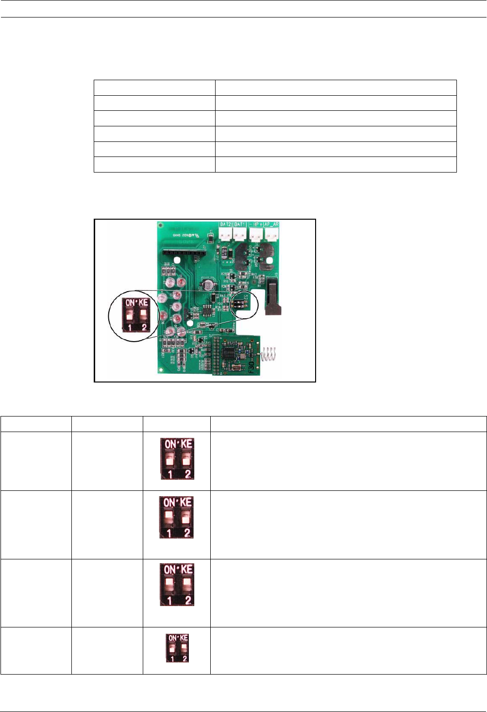
Easy Series Device Specifications and Overview | en 91
Bosch Security Systems, Inc. System Reference Guide F01U087835 | 02 | 2008.10
10.16 wLSN Outdoor Siren
Specifications
Configuration
Use the Outdoor Siren DIP switches to configure the siren for compliance with the laws of the
installation country. Refer to Figure 10.6, Page 91.
Figure 10.6 Outdoor Siren Configuration Switches
Refer to the following table for configurations allowed by the DIP Switch Settings.
Table 10.9 Outdoor Siren DIP Switch Settings
868 MHz ISW-BSR1-WOX
Wire Gauge 0.14 mm to 1.5 mm
Power Two 2 x 13Ah (3.6 VCC nominal)
Outdoor Modulation 1400 – 1600 Hz, excursion of 200 Hz
Sounder 90 to 105 dB at 1m
EN50131-1 EN Environmental class IV outdoor
Configuration Region DIP Switches Configuration
OFF/OFF Default – Siren is limited to 90 sec.
– Flashes every 1.5 sec from 0 - 90 sec of the alarm.
– Flashes every 3 sec from 90 sec - 30 min of the alarm.
– Flash stopped after 30 min.
ON/OFF Spain – Siren is activated for 60 sec, then 30 sec of silence, and then
activated for 60 more sec.
– Flashes every 1.5 sec from 0 - 150 sec of the alarm.
– Flashes every 3 sec from 150 sec - 30 min of the alarm.
– Flash stopped after 30 min.
ON/ON Belgium – Siren is limited to 90 sec.
– Flashes every 1.5 sec from 0 - 90 sec of the alarm.
– Flashes every 3 sec from 90 sec - 30 min of the alarm.
– Flashes every 20 sec from 30 min of the alarm until the siren
is turned off.
OFF/ON Reserved Reserved for future use.
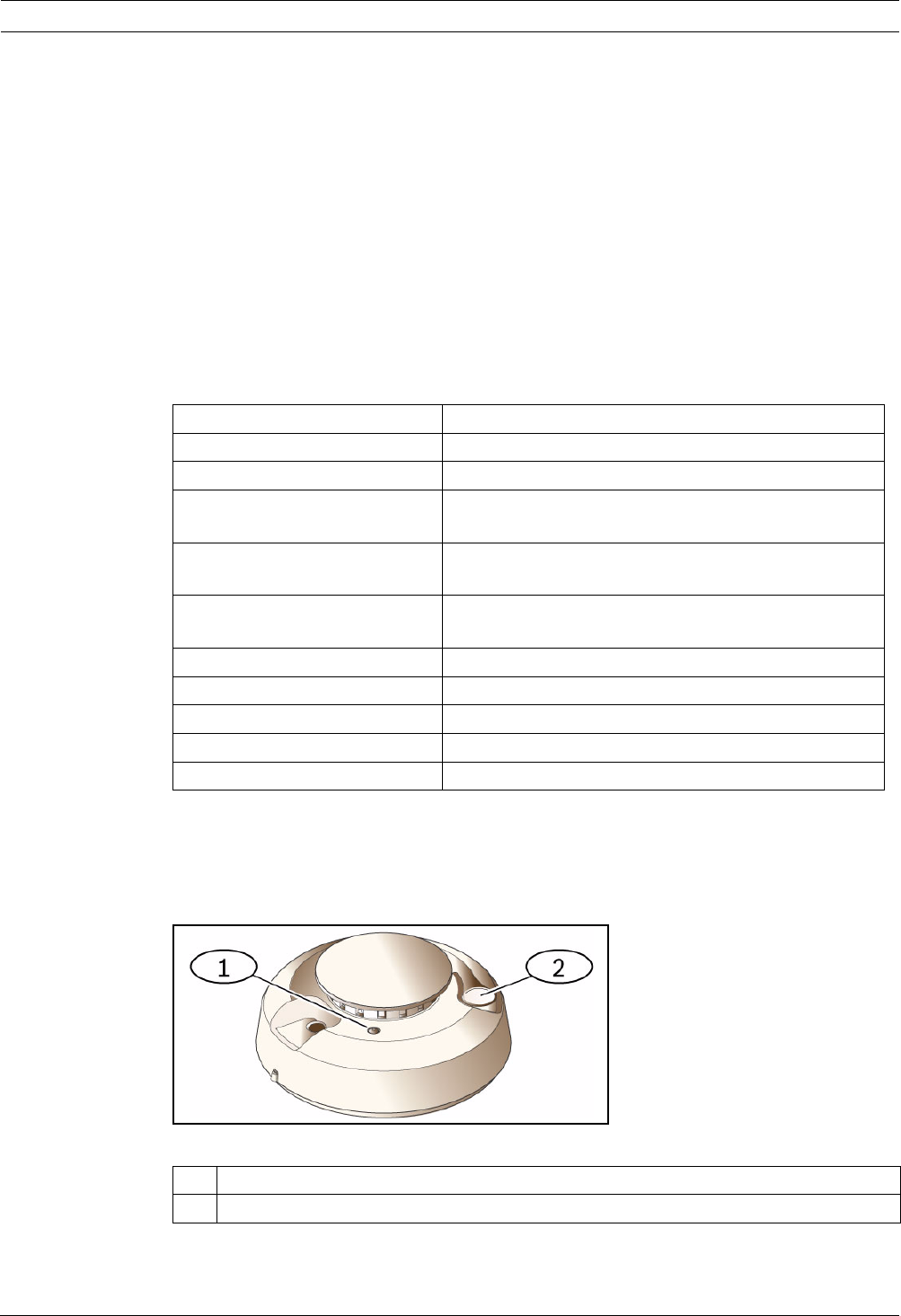
92 en | Device Specifications and Overview Easy Series
F01U087835 | 02 | 2008.10 System Reference Guide Bosch Security Systems, Inc.
10.17 wLSN Smoke and Heat Detectors
The ISW-BSM1-SX (868 MHz) is a wireless smoke detector.
The ISW-BSM1-SY (915 MHz) is a wireless smoke and heat detector that provides fixed
temperature and rate-of-rise sensors.
Under normal conditions, the red LED flashes once every 8 sec while the sensor monitors the
surrounding environment. When the sensor detects smoke, the LED changes from flashing to
steady on and the sounder produces a loud continuous tone.
A self-diagnostic feature monitors detector sensitivity and operational status.
A cover tamper switch transmits a tamper signal when the cover is removed from its base, or
when the unit is pulled away from the wall.
The optical chamber is removable for easy maintenance.
Specifications
Battery Replacement
The LED normally flashes every 8 sec. Replace batteries when the LED stops flashing and the
sensor chirps every 45 sec.
The low battery trouble chirps can be silenced for 24 hours by pushing the Test/Silence
Button. Refer to Figure 10.7 on Page 92 for the location of the Test/Silence Button.
Figure 10.7 wLSN Smoke Detector
868 MHz ISW-BSM1-SX
915 MHz ISW-BSM1-SY
Power/Voltage Two lithium batteries; 3 VDC
Fixed Temperature Sensor (ISW-
BSM1-SY)
+57°C ± 3°C (+135°F ± 5°F)
Raye-of-Rise Sensor (ISW-BSM1-
SY)
+8.3°C/min>+41°C (+15°F>+105°F)
Photoelectric Beam Obscuration
Sensitivity
0.14 ± 0.04 dB/m
Drift Compensation Adjustment 1.64%/m (0.5%/ft) maximum
Average Alarm Current 70 mA
Sounder 85 dBA at 3 m
Self-diagnostics Feature Monitors detector sensitivity and operational status.
EN14604 ISW-BSM1-SX
1 High intensity LED
2 Test/Silence Button

Easy Series Device Specifications and Overview | en 93
Bosch Security Systems, Inc. System Reference Guide F01U087835 | 02 | 2008.10
Smoke Test
Test smoke detectors annually using a listed aerosol smoke tester to simulate an alarm.
Follow the instructions on the can.
The LED should remain on while the detector provides a continuous tone. The detector
automatically resets when smoke is no longer present. A detector that fails to activate with
the Smoke test might require cleaning or replacement.
Sensitivity Test
The detector includes a Sensitivity Level Test mode for determining the detector's sensitivity:
1. Press and hold the Test/Silence button for 4 sec. The LED flashes 1 to 9 times and the
sounder activates.
2. Count the number of LED flashes and use Table 10.10 on Page 93 to determine the status
of the detector's sensitivity and the action to take.
Table 10.10 wLSN Smoke Detector Sensitivity Conditions
Silence an Alarm
Press the Test/Silence Button (refer to Figure 10.7 on Page 92) to silence the sounder during
an alarm. If smoke is still present after a few minutes, the sounder and alarm resume.
LEDs
Table 10.11 wLSN Smoke Detector LED Statuses
i
NOTICE!
To avoid a fire department dispatch, contact the central monitoring station or put the system
into Test mode before activating the detector using this method.
i
NOTICE!
Test mode is seen by the control panel as a test. It does not send an alarm.
Flashes Action Recommended
1 Return device for service or replacement.
2 to 3 Clean the detector and re-test. If error persists, replace the detector.
4 to 7 Normal.
8 to 9 Confirm that the smoke chamber is snapped down securely. Clean the sensor and re-test.
LED Status
Flashing Normal.
On Detects smoke (heat), sending an alarm.
Off Replace the batteries, clean the detector, or replace the optical chamber as required.
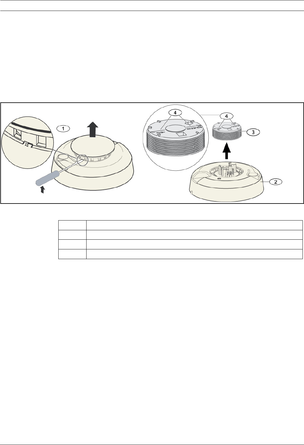
94 en | Device Specifications and Overview Easy Series
F01U087835 | 02 | 2008.10 System Reference Guide Bosch Security Systems, Inc.
Cleaning the Detector and Replacing the Optical Chamber
Clean the detector cover with a dry or damp cloth as needed to keep it free from dust and
dirt. Clean the detector interior at least once a year, or as needed.
To clean the detector:
1. Rotate the detector counter-clockwise to remove it from the mounting base.
2. Remove the batteries.
3. Slide a flat head screwdriver in the slot on the detector cap and gently push down to pry
the cap off. Squeeze the optical chamber where indicated and pull it up and away from
the detector. Refer to Figure 10.8 on Page 94.
Figure 10.8 Remove the Detector Cap and the Chamber
4. Use compressed air or a soft-bristled brush to remove dust and dirt from the smoke
chamber base.
5. Align the new optical chamber with the base and snap into place.
6. To attach the detector cap, line the cap up with the detector, press the cap onto the
detector, and turn the cap clockwise to snap it firmly into place.
7. Observing the proper polarity, install the batteries and the battery cover. If the batteries
are not installed, the detector does not properly fit onto the mounting base.
8. Mount the detector onto the mounting base.
9. Test the detector's sensitivity.
Refer to Section Sensitivity Test on Page 93.
1 Remove detector cap
2 Smoke Chamber Base
3 Optical Chamber
4 Alignment Arrows
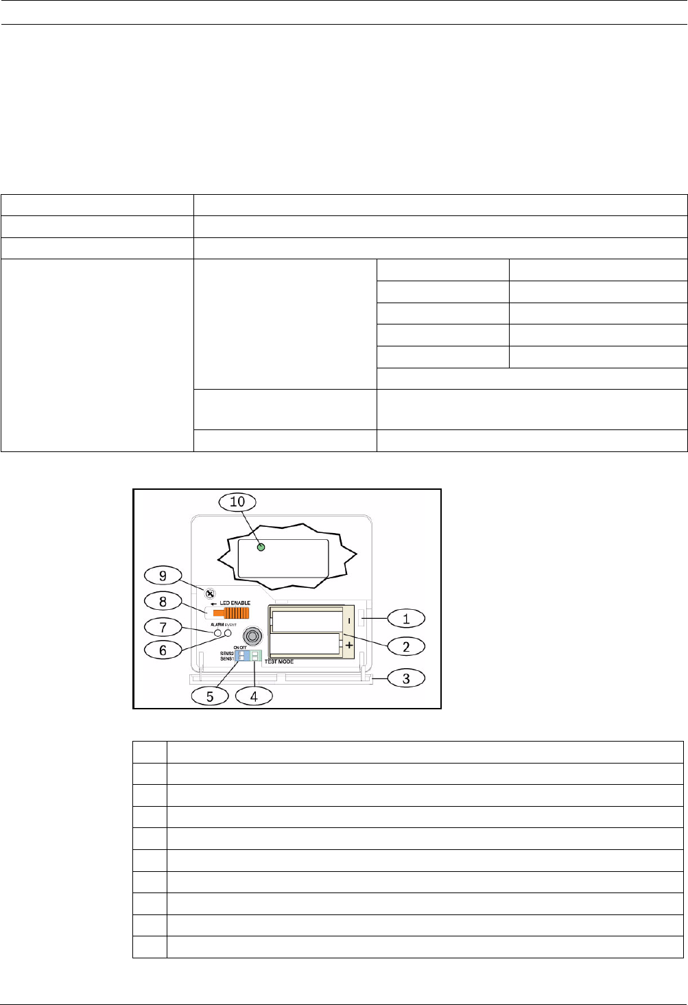
Easy Series Device Specifications and Overview | en 95
Bosch Security Systems, Inc. System Reference Guide F01U087835 | 02 | 2008.10
10.18 wLSN Glassbreak Detector
Specifications
The wLSN Glassbreak Detector is a wireless transmitter used for detecting breaking glass.
A cover-and-wall tamper switch transmits a tamper signal when the cover is removed from its
base, or when the unit is pulled away from the wall.
Specifications
General Overview
Figure 10.9 wLSN Glassbreak Detector Front Layout
868 MHz ISW-BGB1-SAX
915 MHz ISW-BGB1-SAY
Power/Voltage 2 AA batteries, 1.5 V alkaline
Acoustic Capabilities Glass types and thicknesses Type Thickness
Plate 0,24 cm to 0,95 cm
Tempered 0,32 cm to 0,95 cm
Laminated* 0,32 cm to 1,43 cm
Wired 0,64 cm
* Protected only if both panes of glass are broken.
Minimum pane size for all
types of glass
28 cm x 28 cm
Range Maximum 7.6 m; no minimum range
1 Service door tamper switch
2 AA batteries
3 Service door
4 Test Mode pads
5 Sensitivity DIP switches
6Event LED
7 Alarm LED
8 LED enable switch (off position)
9 Housing screw
10 RFSS Mode LED (remove housing screw and cover piece)
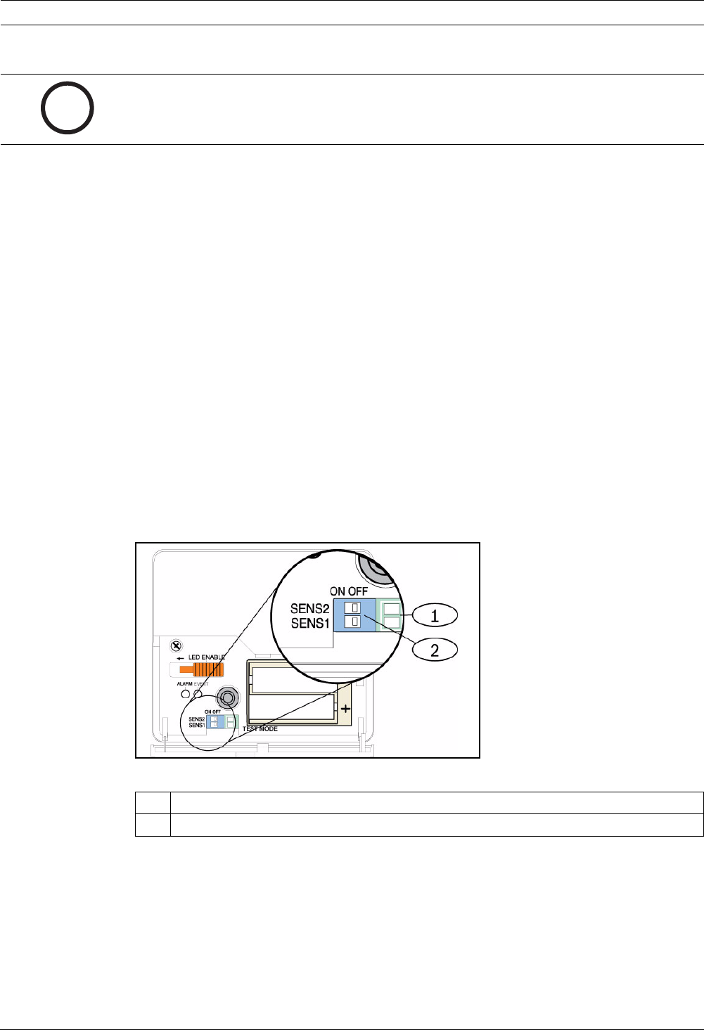
96 en | Device Specifications and Overview Easy Series
F01U087835 | 02 | 2008.10 System Reference Guide Bosch Security Systems, Inc.
Installation Considerations
For the best detector performance, select a mounting location that is:
– within 7.6 m of the protected glass.
– within clear view of the protected glass.
– at least 2 m from the floor.
– at least 1 m from forced-air ducts.
– at least 1 m from sirens or bells greater than 5 cm in diameter.
– on a window frame if any heavy window covering is present.
Avoid mounting the detector:
–in a corner.
– on the same wall as the protected glass.
– on free-standing posts or pillars.
– in rooms with noisy equipment such as air compressors, bells, and power tools.
Sensitivity Settings
1. If the front housing is attached, carefully open the service door (Item 3, Figure 10.9 on
Page 95).
2. Enable the LEDs for test purposes by sliding the LED ENABLE switch (Item 8, Figure 10.9
on Page 95) in the direction the arrow points (above the switch). An orange flag
protrudes from the side of the detector.
Refer to Figure 10.10 on Page 96.
Figure 10.10 wLSN Glassbreak Sensitivity Switches
i
NOTICE!
Glassbreak detectors are intended only as a component of a perimeter protection system. You
should always use a motion detector in conjunction with a glassbreak detector.
1Test pads
2 Sensitivity switches
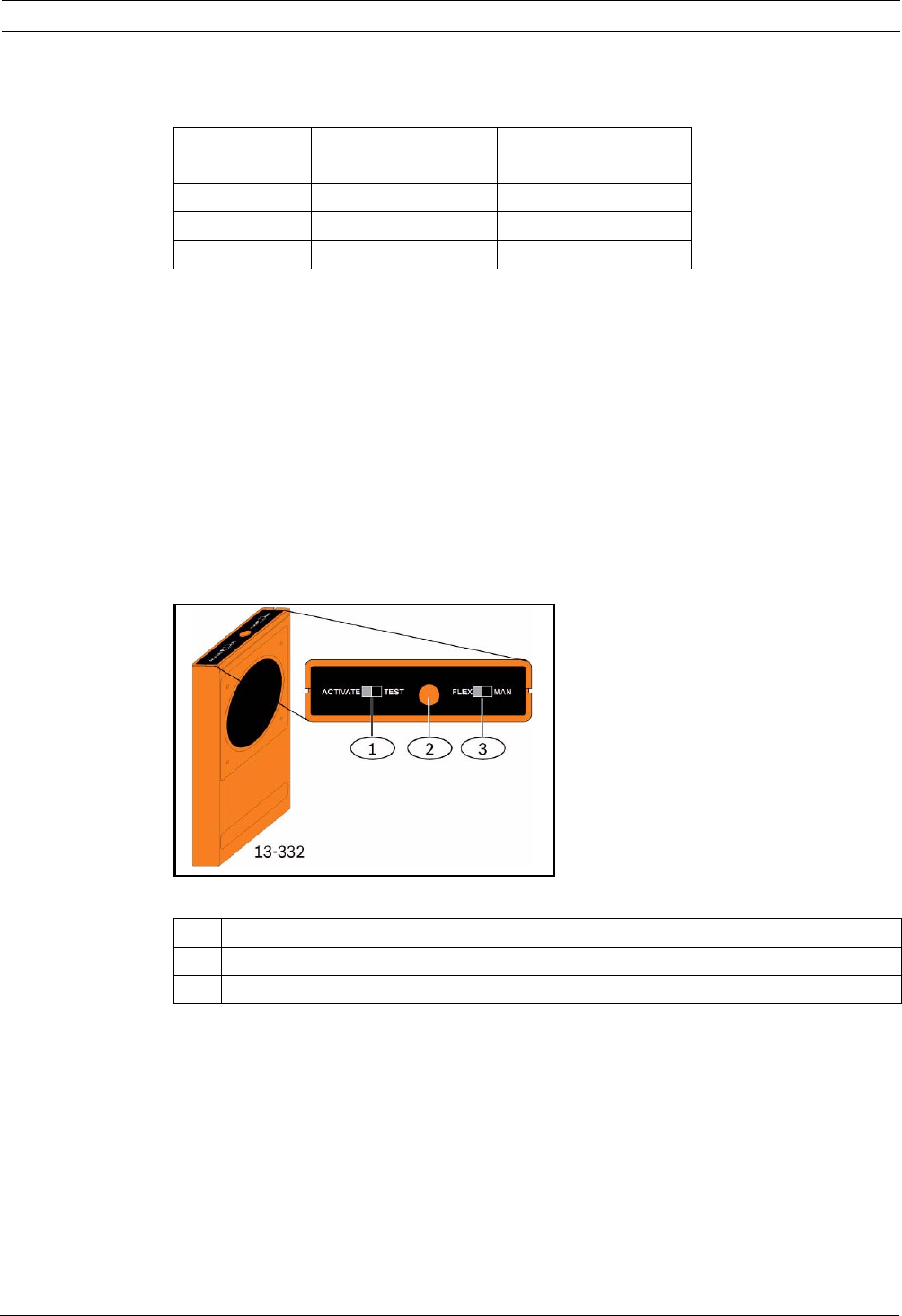
Easy Series Device Specifications and Overview | en 97
Bosch Security Systems, Inc. System Reference Guide F01U087835 | 02 | 2008.10
3. Determine the sensitivity setting for your application.
Refer to Table 10.12.
Table 10.12 wLSN Glassbreak Detector Sensitivity Settings
4. Use a small screwdriver to move the sensitivity switches. Use the settings determined in
Step 3.
5. Turn on any sources of noise (such as machinery, office, or audio equipment) in the area.
6. Observe the green event LED (Item 6, Figure 10.9 on Page 95) for approximately 1 min. If
the green LED flashes, relocate the unit or reduce the sensitivity by adjusting the
sensitivity switch.
7. Repeat Steps 3 through 6 until you achieve the best sensitivity level.
8. After setting the sensitivity, slide the LED enable switch (Item 8, Figure 10.9 on Page 95)
to the OFF position.
Testing
Test the detector at least once each year. Test the detector with the 13-332 Sound Sensor
Tester.
Figure 10.11 13-332 Sound Sensor Tester
Sensitivity SENS1 SENS2 Approximate Range
Maximum OFF OFF 7,6 m
Medium ON OFF 4,6 m
Low OFF ON 3 m
Lowest ON ON 1,5 m
1 Activate/Test switch
2 Start button
3 Flex/Man switch

98 en | Device Specifications and Overview Easy Series
F01U087835 | 02 | 2008.10 System Reference Guide Bosch Security Systems, Inc.
Entering Test Mode
Place the detector in Test Mode. In Test Mode, the detector's LED disable switch (Item 8,
Figure 10.9 on Page 95) is overridden. You can enter the Test Mode locally or remotely.
To enter the Test Mode locally:
1. Carefully open the service door of the detector.
2. Insert a screwdriver into the slot next to the sensitivity switches that contains the test
pads (Item 1, Figure 10.9 on Page 95).
3. Momentarily short both test pads together with the tip of the screwdriver, or other
metallic conductive object.
The Event LED (green) (Item 6, Figure 10.9 on Page 95) flashes once per sec. If the green
LED does not flash, repeat Steps 10 and 11.
To enter the Test Mode remotely:
1. Stand within 3 m of the detector.
2. Move the switches on top of the 13-332 Tester to ACTIVATE and to MAN modes (Items 1
and 3, Figure 10.9 on Page 95).
3. Point the front of the tester towards the detector and press the red Start button on top
(Item 2, Figure 10.9 on Page 95).
The tester buzzes and the green LED on the detector flashes once per sec. If the green LED
does not flash, move closer to the detector and repeat the procedure.
Testing
Testing the Detector (Flex and Audio Signals)
1. Set the 13-332 Tester switches to the TEST and FLEX positions (Items 1 and 3,
Figure 10.9 on Page 95).
2. Press the red Start button (Item 2, Figure 10.9 on Page 95). The tester activates and
starts an eight-sec armed period.
3. If window coverings are present, close them fully.
4. Hold the 13-332 Tester near the point on the glass farthest from the detector. If window
coverings are present, hold the tester between the glass and window coverings.
5. Carefully strike the glass with a cushioned tool. The 13-332 Tester responds by producing
a burst of glass break audio.
If the detector receives both the flex and audio signals properly, its red Alarm LED lights for
3 sec.
If the red LED does not light, return to Section 9.0 RFSS Site Testing on page 81 to reposition
the detector.
DANGER!
The 13-332 Sound Sensor Tester produces extremely loud sounds and can be hazardous to
hearing when used at close range. Do not point the 13-332 towards someone's head.
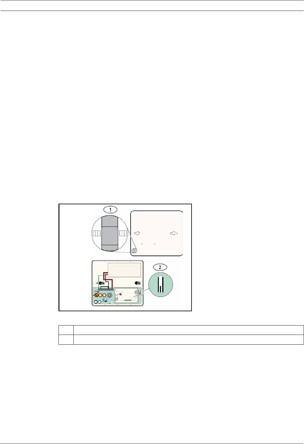
Easy Series Device Specifications and Overview | en 99
Bosch Security Systems, Inc. System Reference Guide F01U087835 | 02 | 2008.10
Exiting Test Mode
To exit the Test Mode locally:
1. Carefully open the service door of the detector.
2. Insert a screwdriver into the slot next to the sensitivity switches that contains the test
pads (Item 1, Figure 10.9 on Page 95).
3. Momentarily short both test pads together with the tip of the screwdriver, or other
metallic conductive object.
When the detector exits Test Mode, the green Event LED (Item 6, Figure 10.9 on Page 95)
stops flashing. If the Event LED continues to flash, repeat Steps 2 and 3.
To exit the Test Mode remotely:
1. Stand within 3 m of the detector.
2. Move the switches on top of the 13-332 Tester to ACTIVATE and to MAN modes (Items 1
and 3, Figure 10.9 on Page 95).
3. Point the front of the tester towards the detector and press the red Start button on top
(Item 2, Figure 10.9 on Page 95).
The tester buzzes.
Entering RFSS Mode with the Wall Tamper Removed
To enter RFSS Mode if the wall tamper tab is removed:
1. Remove and reinsert the batteries.
2. Press and hold the wall tamper switch.
Refer to Figure 10.12 on Page 99.
Figure 10.12 Wall and Cover Tamper Switches
3. Quickly press and release the cover tamper switch four times within 10 sec of reinserting
the batteries. Refer to Figure 10.12 on Page 99. The detector enters RFSS Mode.
Low Battery Indication
The detector indicates a low battery condition in two ways:
– If the LEDs are enabled, both flash simultaneously every sec.
– A low battery status indication is sent to the control panel.
The LED flashing and a low battery indication at the control panel are independent of each
other and do not necessarily occur at the same time. Receiving either condition indicates a
low battery.
1 Wall tamper switch (back of detector)
2 Cover tamper switch (inside of detector)

100 en | Device Specifications and Overview Easy Series
F01U087835 | 02 | 2008.10 System Reference Guide Bosch Security Systems, Inc.
10.19 wLSN Water Sensor/Low-temperature Sensor
The wLSN Water Sensor/Low-temperature Sensor detects water spilled or leaking onto a
solid surface. It can also be used to monitor temperature to warn of potential water pipe
freezing. If temperatures fall below +7°C (+45°F) for more than 30 sec. the sensor sends a
signal to the wLSN Hub.
Specifications
Installation Considerations
The wLSN Water Sensor/Low-temperature Sensor is not intended to:
– monitor water levels in storage tanks or other liquids
– be permanently submerged in water
– detect absence of water
Test and Enable wLSN Water Sensors/Low-temperature Sensors
Test each newly discovered device during the Point Test to enable the device. If specific point
numbers are preferred, test devices in the appropriate order.
Testing and Enabling When Both Sensors are Required
1. During the Point Test, test the low-temperature sensor first. Refer to Table 10.13,
Page 100 for instructions.
The system announces "Point xx was tested."
2. Test the water sensor. Refer to Table 2 for instructions.
Testing and Enabling When Only the Water Sensor is Required
During the Point Test, test the water sensor. Refer to Table 10.13, Page 100 for instructions.
The system announces "Point xx was tested."
Testing and Enabling When Only the Low-temperature Sensor is Required
During the Point Test, test the low-temperature sensor. Refer to Table 10.13, Page 100 for
instructions.
The system announces "Point xx was tested."
Do not connect the water sensor probe.
Table 10.13 Water Sensor/Low-temperature Sensor Test and Enable Procedures
868 MHz ISW-BWL1-SX
915 MHz ISW-BWL1-SY
Power/Voltage Two AA batteries, 2.3 VDC to 3.0 VDC
Relative Humidity Up to 95%, non-condensing
Temperature (operating) -10°C to +55°C (+14°F to +131°F)
Temperature (alarm) <+7°C (+45°F)
EN50131-1 Environmental Class II
Sensor To Test
Water Select one of the following methods:
– Short the water probe pins for at least 5 sec. Refer to Figure 10.13, Page 101.
– Submerge the water probe in water for at least 5 sec.
Low-temperature Short the "T" pads for at least 5 sec. Refer to Figure 10.13, Page 101.
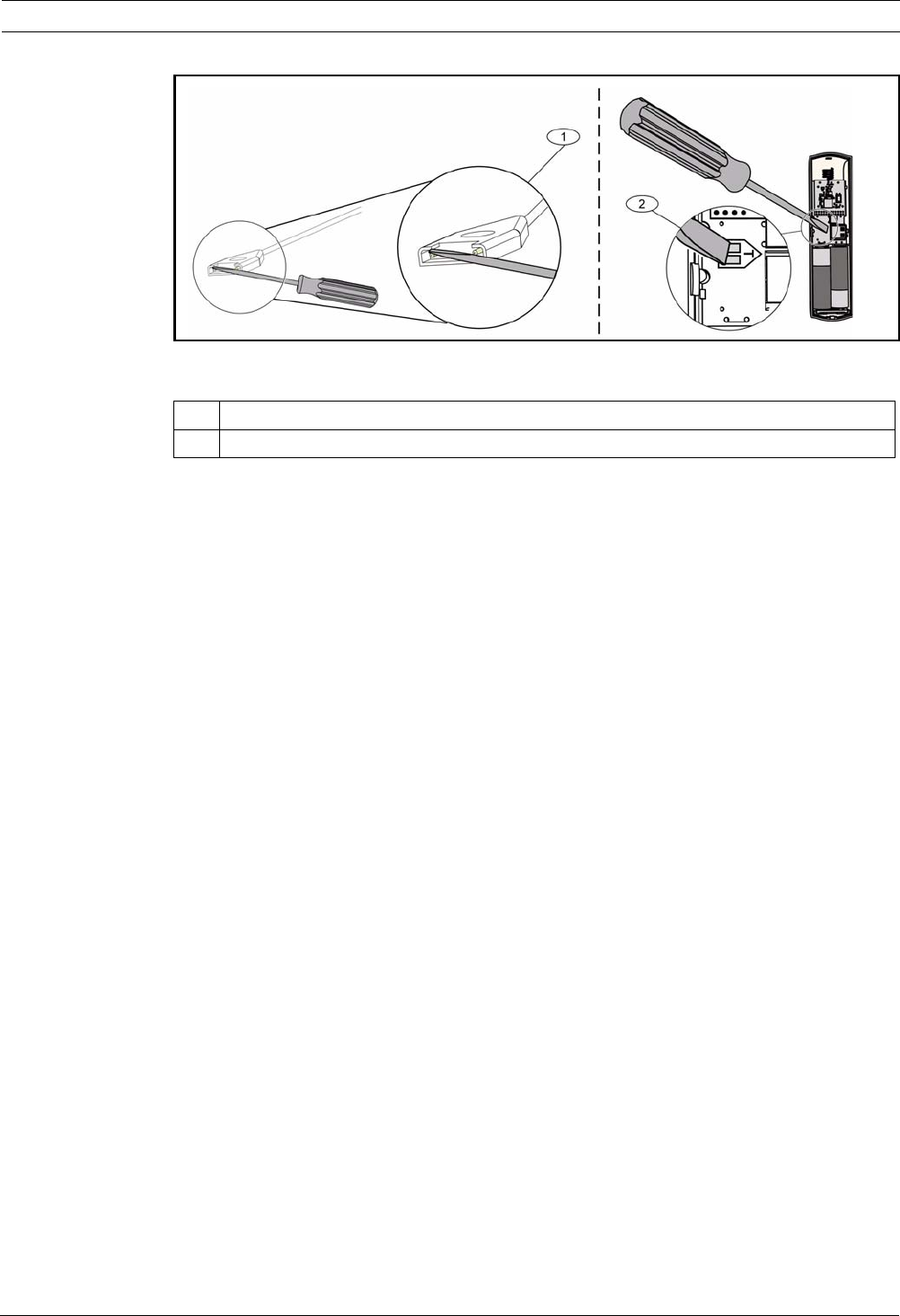
Easy Series Device Specifications and Overview | en 101
Bosch Security Systems, Inc. System Reference Guide F01U087835 | 02 | 2008.10
Figure 10.13 Enabling the Water Probe and Low-Temperature Functions
1 Water sensor
2 Low-temperature sensor

102 en | Programming Details and Defaults Easy Series
F01U087835 | 02 | 2008.10 System Reference Guide Bosch Security Systems, Inc.
11 Programming Details and Defaults
This section defines the primary function of the major programming items.
This section also lists the programming defaults for the most frequently used country codes.
11.1 Programming Item Programming Details
102. Country Code
Select the appropriate code for country-specific operation.
107. Fire Bell Cut-off Time
Enter how long the fire alarm sounds at bell outputs and at the control center.
108. Intrusion Bell Cut-off Time
Enter how long the intrusion alarm sounds at bell outputs and at the control center.
110. Intrusion Abort Window
Enter how long the control panel waits to send an alarm report after an alarm occurs.
111. Fire Alarm Cancel Window
Enter how long a user has to cancel a fire alarm report after the system sends the report to
the central station. If a fire alarm is acknowledged during the cancel window, the system
sends a cancel report to the central station. An entry of 0 disables this feature.
112. Intrusion Cancel Window
Enter how long a user has to cancel an intrusion alarm report after the system sends the
report to the central station.
115. Chime Mode Operation after System Off
Determines Chime Mode operation after the system is turned off.
116. Automatic Test Report Frequency
Determines how often the control panel sends the automatic test report.
118. RPS Passcode
Enter the 6-digit passcode that allows access to the control panel from RPS.
124. Point Alarm Verification
Determines the level of alarm verification required by point before generating an intrusion
alarm condition.
125. Faulted Points Allowed Threshold
Determines the maximum number of faulted points that are disabled while the system is on.
126. Exit Delay
Enter how long the user has to exit the building before the system turns on.
127. Entry Delay
Enter how long the user has to enter the building and turn off the system before an alarm
condition occurs.
131. Swinger Bypass Count
Enter the number of alarm reports allowed from a point while the system is on before the
point is bypassed.
133. System On Order Options
Determines the order that system-on options are announced to the user.
134. Cross Zone Timer
Enter how long the system waits for at least two Cross Zone points to be faulted before the
control panel sends a Verified Alarm report to the central station.

Easy Series Programming Details and Defaults | en 103
Bosch Security Systems, Inc. System Reference Guide F01U087835 | 02 | 2008.10
140. Demo Mode
Demo Mode controls how telephone messages are announced by the system: either only over
the telephone, or over the telephone and through all idle control centers (control centers that
are not currently engaged in a command). Set Demo Mode to 2 (Demo Mode Auto On/Off).
Enter the telephone menu.
On an idle control center, press the [i] button to either turn on or off the announcement of
telephone messages through all idle control centers. When you exit the telephone menu and
end the phone session, the system turns Demo Mode off.
142. Restrict Installer Passcode
If set to 0, the Master User must enable the Installer passcode before a person logged in with
the Installer passcode can perform any tasks through the phone menu or RPS; enabling the
Installer passcode grants it Level 3 access. The Installer passcode remains at Level 3 until an
exit delay.
If set to 0, and the Installer is granted access while the control panel is armed, the
programming items are limited.
To enable the Installer Passcode:
1. From the control center, the Master User enables enters the passcode. When the
validation for the Master User passcode expires, the Installer passcode is enabled.
2. Using a token, the Master User presents the token several times until the control center
speaks "Turning your system off". If the Master User token is presented again, the
Installer passcode is disabled.
3. From the phone interface, the Master User enters the passcode, then presses [3] for
System Maintenance, [3] for System Test menu, and then [6] to enable the Installer's
passcode.
145. Test Report Day of Week
Select the day that the control panel sends the test report.
146. Test Report Day of Month
Enter the day of the month that the control panel sends the test report.
148. Arming Beeps/Graduated Annunciation
Select whether the Intrusion and Intrusion and Fire Output Function types beep when the key
fob is used to arm or disarm the control panel.
150. Wireless Jam Detect Level
Configure the jam detect level of the wireless devices.
163. Silence Trouble Tones
Silence annunciation of trouble tones.
164. System Inactivity Time (Hours)
Enter the number of hours that the system must be turned off before it sends the System
Inactive report.
165. System Inactivity Time (Days)
Enter the number of days that the system must be turned off before it sends the System
Inactive report.
166. System Inactivity Time (Weeks)
Enter the number of weeks that the system must be turned off before it sends the System
Inactive report.
168. Audio Verification Command Set
Select the command set that the control panel uses for internal alarm verification. Press the
[*] key on the phone to enable the microphone on the control centers. This allows the central
station operator to hear noise on the premises. This option only effects the button presses on
the phone while an audio verify session is active between the control panel and the central
station operator.

104 en | Programming Details and Defaults Easy Series
F01U087835 | 02 | 2008.10 System Reference Guide Bosch Security Systems, Inc.
224. RPS Automatic Call In Time (Hours)
202. PSTN or GSM Connection
Select the type of telephone connection the system will use to send reports to the central
station.
203. Voice Format Repeat Count
Enter the number of times the system repeats a voice report during the phone call.
204. Voice Format Message Delivery Attempts
Enter how many times the system attempts to deliver a voice format message.
217. Emergency Call Override Number Delay
Enter the amount of time the system waits before sending reports if an emergency number is
dialed.
222. Phone Answer Ring Count
Enter the number of rings before the system answers an incoming call.
223. Bell Test
This programming item applies to all Intrusion output functions and to all arming modes.
0 = No closing ring-back or bell test; 1 = Enabled
If closing reports are disabled, the outputs turn on for 1 sec at the end of Exit Delay.
If closing reports are enabled, the outputs turn on for 1 sec when the control panel receives a
closing report acknowledgement from the central station.
Select the hour when the control panel calls RPS.
225. RPS Automatic Call in Time (Minutes)
Select the minute when the control panel calls RPS.
227. RPS Automatic Call in Time (Day of Week)
Select the day of the week when the control panel calls RPS.
228. RPS Automatic Call in Time (Day of Month)
Select the day of the month when the control panel calls RPS.
229. RPS Automatic Call in Phone Number
Enter the phone number that the control panel uses to call RPS.
245. RPS Automatic Call in Method
Select whether the control panel uses a phone number or an IP address to call RPS.
246. RPS Port Number
Enter the port number for contacting RPS when the automatic call in occurs over a network
connection.
305. Route Attempts
Enter the number of times the system attempts each destination in the selected route if the
first attempt fails.
601. Key Fob Duress
Select whether or not a wireless key fob sends a Duress event when the Arm and Disarm
buttons are pressed and held together.

Easy Series Programming Details and Defaults | en 105
Bosch Security Systems, Inc. System Reference Guide F01U087835 | 02 | 2008.10
611. Output 1 Type
–Disabled: Output is disabled.
–Intrusion: Output turns on when intrusion alarm occurs. To turn off output, turn off
system, or wait until end of intrusion bell cut-off time.
–Fire: Output turns on when a fire alarm occurs. To turn off output, turn off system if it is
already on, or wait until end of fire bell cut-off time.
–Fire Latching: Output turns on when a fire alarm occurs. To turn off output, turn off
system if it is already on, or acknowledge alarm if system is off.
–Intrusion and Fire: Output turns on when an intrusion or fire alarm occurs. To turn off
output, turn off system, or wait until end of bell cut-off time. Fire alarms take priority over
intrusion alarms.
–Intrusion and Fire Latching: Output turns on when an intrusion or fire alarm occurs. To
turn off output, turn off system if it is already on, or acknowledge alarm if system is off.
Fire alarms take priority over intrusion alarms.
–System Reset: Output is normally on. Output turns off for approximately 10 sec when
system is reset. Use this function to supply power to devices such as four-wire smoke
detectors that require power interruption to reset a latching alarm condition
–System On: Output turns on when the system is turned on, and remains on until system
is turned off.
–System Ready: Output turns on when the system is ready to turn on (no faulted points or
system troubles exist).
–Key Fob On/Off: Output turns on or off when the user presses the key fob's or
key.
–Key Fob 2-sec Pulse: Output turns on for two seconds when the user presses the key
fob's or key.
–User Controlled: Output turns on or off when a user or the installer uses the Operate
Outputs option from the phone menus.
–Interior Intrusion and Fire: Output turns on when an interior intrusion or fire alarm
occurs. To turn off output, turn off system, or wait until end of bell cut-off time. Fire
alarms take priority over intrusion alarms.
–System On (Unoccupied): Output turns on when the system is turned On (Unoccupied)
and there are no bypassed or force-armed points.
–Intrusion and Fire:
– Output turns on when any alarm (Intrusion or Fire) occurs. To turn off the output,
turn off the system, or wait until the end of the bell cut-off time.
– When a fire alarm occurs, this output function provides only a steady output (no
Temporal Code 3 or Pulsed cadence).
– Fire alarms take priority over Intrusion alarms.
880. Alarm Message Minimum Repeat Time
Enter how long the control center waits between alarm message announcements before
repeating the message even if the control center's proximity sensor detects motion.

106 en | Programming Details and Defaults Easy Series
F01U087835 | 02 | 2008.10 System Reference Guide Bosch Security Systems, Inc.
9xx1. Point Types
–Disabled: Point is disabled.
–Perimeter (Entry or Exit): If faulted and the system is on, Entry Delay starts. An alarm
occurs if the system is not turned off when Entry Delay ends.
–Interior (Follower): If the system is on occupied, it ignores these points. If the system is
on unoccupied, a faulted interior point starts an alarm. These points are ignored during
Exit and Entry Delay times.
–Perimeter Instant: If faulted when the system is on, a local alarm occurs
–24-Hour: If faulted, an alarm always occurs. To restore a 24-hour point, turn the system
off if it is on, or acknowledge the alarm if the system is off.
–Fire Verified: If faulted, fire verification occurs. If a second fire event occurs during the
two-min. wait period, a fire alarm occurs. If no second fire event occurs, the system
returns to normal.
–Fire Instant: If faulted, a fire alarm always occurs.
–Silent Panic: If faulted, an alarm always occurs. There is no visual or audio indication of
the alarm.
–Interior Walkthrough: If faulted and the system is on custom protection, Entry Delay
starts. If the system is on occupied or unoccupied, this point functions as an interior
point.
–Perimeter Exit Cancel: If faulted and restored during Exit Delay, Exit Delay stops and the
system immediately turns on.
–Momentary Keyswitch: Turn the system on or off using a momentary keyswitch.
–Maintained Keyswitch: Turn the system on or off using a maintained keyswitch.
–24-Hour Trouble: If faulted, a trouble condition always occurs. To restore a 24-hour
trouble point, turn they system off if it is on, or acknowledge the alarm if the system is
off.
–User Emergency, 24-hour supervisory point type:
– If the point's circuit style = 0, an open or shorted circuit creates a tamper condition.
An off-normal circuit creates an alarm condition.
– If the point's circuit style = 1, an open or shorted circuit creates an alarm condition.
– Refer to Circuit Style on page 68 for more information.
– If User Emergency is assigned to a wireless detector, any off-normal alarm condition
creates an alarm condition.
– To restore a user emergency point, turn the system off if it is on, or acknowledge the
alarm if the system is off.
9xx6. Alarm Verification
Select whether or not the central station can verify the alarm when it receives an alarm report
from the point and the report is acknowledged.

Easy Series Programming Details and Defaults | en 107
Bosch Security Systems, Inc. System Reference Guide F01U087835 | 02 | 2008.10
11.2 Country Codes
The country code sets the control panel to the appropriate country-specific defaults for your
installation.
Country Code Country Code
Argentina 01 Israel 63
Australia 02 Italy 25
Austria 03 Japan 26
Belarus 62 Lithuania 29
Belgium 04 Luxembourg 20
Bosnia 65 Malaysia 32
Brazil 05 Mexico 34
Bulgaria 06 Netherlands 35
Canada 07 New Zealand 36
China 08 Norway 38
Croatia 10 Poland 41
Czech Republic 12 Portugal 42
Denmark 13 Romania 43
Egypt 14 Russian Federation 44
Finland 16 Spain 51
France 17 Sweden 52
Germany 18 Taiwan 54
Greece 19 Thailand 55
Hong Kong 20 Turkey 56
Hungary 21 Ukraine 62
India 22 United Arab Emirates 65
Indonesia 23 United Kingdom 57
Ireland 24 United States 58

108 en | Programming Details and Defaults Easy Series
F01U087835 | 02 | 2008.10 System Reference Guide Bosch Security Systems, Inc.
11.3 Country Code Specific Default Programming Codes
Country Codes
Prog Item# ↓
107
108
125
126
127
133
136
137
138
204
211
212
213
214
216
306
9011
9021
9031
9041
9051
9061
9071
9081
9012
9022
9032
9042
9052
9062
9072
9082
9092
9102
9112
9122
9132
9142
9152
9162
9172
9182
9192
535513553575153
535513553575153
03333033303303
60 60 60 60 30 45 60 30 45 60 60 60 45 30
30 30 30 30 30 45 30 25 30 30 30 30 45 20
11111313311331
01000000000000
00000100000000
00000000000000
33113312335335
00000000000053
00000000000053
00000000000053
00000000000043
110 112 000 112 112 112 000 112 112 110 000 112 999 113
00000000000000
61661666166611
13112111211183
13112312213133
13112312213133
13112313312132
23222223322232
23222224322222
23222223424224
20222222022200
20222022022200
20222022022200
20222022022200
20222022022200
20222022022200
20222022022200
20222022022200
20222022022200
20222022022200
20222022022200
20222022022200
20222022022200
20222022022200
20222022022200
20222022022200
20222022022200
20222022022200
20222022022200

Easy Series Programming Details and Defaults | en 109
Bosch Security Systems, Inc. System Reference Guide F01U087835 | 02 | 2008.10
Country Codes
Prog Item# ↓
9202
9212
9222
9232
9242
9252
9262
9272
9282
9292
9302
9312
9322
814
824
834
844
861
611
621
631
641
642
121
600
115
116
128
132
147
153
159
160
344
403
9015
9025
9035
9045
9055
9065
9075
9085
163
168
20222022022200
20222022022200
20222022022200
20222022022200
20222022022200
20222022022200
20222022022200
20222022022200
20222022022200
20222022022200
20222022022200
20222022022200
20222022022200
01001100100020
01001100101022
01001100101022
01001100101022
46444446644644
555555551455555
55555555555556
56777777657718
57555655755595
01001100100001
22222282222222
01111111101111
02202200200002
00000000000100
11011111111111
00111010001110
00000000000010
11111011111101
01111111101110
11111101111111
33333333333333
33333333333333
66666665466666
66666665466666
66666665466666
66666665466666
66666665466666
66666665466666
66666665466666
66666665466666
10111111111111
00000000100000

110 en | Programming Details and Defaults Easy Series
F01U087835 | 02 | 2008.10 System Reference Guide Bosch Security Systems, Inc.
Country Codes
Prog Item# ↓
29 30 35 38 41 42 43 44 51 52 53 56 57
107
108
125
126
127
133
136
137
138
204
211
212
213
214
216
306
9011
9021
9031
9041
9051
9061
9071
9081
9012
9022
9032
9042
9052
9062
9072
9082
9092
9102
9112
9122
9132
9142
9152
9162
9172
9182
9192
53355255255515
533552352 5515
3333383333030
60 60 60 60 60 30 30 60 30 60 60 60 45
30 30 20 30 30 30 15 45 20 30 30 30 45
1133131333114
0000001000000
0000000000000
0000000000000
1333121133313
0000030110005
0000000110005
0000000000005
0000000000000
000 112 000 112 000 112 000 000 000 112 110 000 000
0000000100000
6166666666661
1311111111118
1312121222113
1312121222113
1312121222113
2322222222223
2322222222222
2322222222222
2022222202220
2000222200220
2000222200220
2000222200220
2000222200220
2000222200220
2000222200220
2000222200220
2000202200220
2000202200220
2000202200220
2000202200220
2000202200220
2000202200220
2000202200220
2000202200220
2000202200220
2000202200220
2000202200220

Easy Series Programming Details and Defaults | en 111
Bosch Security Systems, Inc. System Reference Guide F01U087835 | 02 | 2008.10
Country Codes
Prog Item# ↓
29 30 35 38 41 42 43 44 51 52 53 56 57
9202
9212
9222
9232
9242
9252
9262
9272
9282
9292
9302
9312
9322
814
824
834
844
861
611
621
631
641
642
121
600
115
116
128
132
147
153
159
160
344
403
9015
9025
9035
9045
9055
9065
9075
9085
163
168
2000202200220
2000202200220
2000202200220
2000202200220
2000202200220
2000202200220
2000202200220
2000202200220
2000202200220
2000202200220
2000202200220
0100010000002
0100010000002
0100010000002
0100010000002
4644444444444
5555555155555
5555555355555
7657777777571
5756585556555
0111010111000
2222222222222
1111111111011
0200000200000
0000001120000
1111111111111
1000111000010
0000000000001
1100111011110
1111111011011
1111111111111
3333333133330
3333333133333
6666666666666
6666666666666
6666666666666
6666666666666
6666666666666
6666666666666
6666666666666
6666666666666
1111111111111
0000000000000

112 en | Agency Approvals and Requirements Easy Series
F01U087835 | 02 | 2008.10 System Reference Guide Bosch Security Systems, Inc.
12 Agency Approvals and Requirements
12.1 Certifications and Approvals
Compliance with specific standards, such as SIA CP-01 and DD243, reduces false alarms and
is required in many locations.
The Easy Series Intrusion Control Panel is designed to comply with the following
certifications, approvals, and standards:
– ANSI/SIA CP-01 False Alarm Immunity
–
– EN50131-1 Security Grade 2, Environmental Class II*
– EN 50131-3, EN 50131-5-3, EN 50131-6, IP30 - IK04
(EN50529 - EN50102 )
– DD243*
– PD6662*
–CCC*
– UL Standards:
– UL365, Police Station Burglar Alarm Units and
systems
– UL609, Local Burglar Alarm Units and Systems
– UL985, Household Fire Warning System Units
– UL1023, Household Burglar-alarm System Units
– UL1076, Proprietary Burglar Alarm Units and
Systems
–cUL Standards:
– CAN/ULC-S545, Residential Fire Warning
System Control Units
– CAN/ULC-S545, Residential Fire Warning
System Control Units
– CAN/ULC-S303, Local Burglar Alarm Units and
Systems
– C1076, Proprietary Burglar Alarm Units and
Systems
– C1023, Household Burglar Alarm Units
– FCC
– Industry of Canada (IC)
–A-Tick*
–C-Tick*
– TBR21 for PSTN*
– INCERT (Belgium) *
– CSFM Listing - Control Unit Household
– Japan Approvals Institute for Telecommunications
Equipment (JATE) *
* Not investigated by Underwriters Laboratories, Inc.
i
NOTICE!
The ITS-DX4020-G has not been tested by UL.

Easy Series Agency Approvals and Requirements | en 113
Bosch Security Systems, Inc. System Reference Guide F01U087835 | 02 | 2008.10
12.2 FCC
Part 15
This equipment was tested and found to comply with the limits for a Class B digital device,
pursuant to Part 15 of the FCC rules. These limits are designed to provide reasonable
protection against harmful interference when the equipment is operated in a commercial
environment.
This equipment generates, uses, and can radiate radio frequency energy. If this equipment is
not installed and used according to this document, it might cause harmful interference to
radio communications.
Operation of this equipment in a residential area is likely to cause harmful interference, in
which case the user must correct the interference.
Part 68
This equipment complies with Part 68 of FCC rules. A label contains, among other
information, the FCC registration number and ringer equivalency number (REN). If requested,
this information must be provided to the telephone company.
The Bosch Security Systems Easy Series Intrusion Control Panel is registered for connection
to the public telephone network using an RJ38X or RJ31X jack.
The REN determines the number of devices that can be connected to the telephone line.
Excessive REN's on the telephone line might result in the devices not ringing in response to an
incoming call. In most, but not all areas, the sum of the REN's should not exceed five. To
determine the number of devices that can be connected to the telephone line, contact the
telephone company for the maximum REN for the calling area.
The telephone company notifies you if this equipment harms the telephone network. If
advance notice is not practical, the telephone company notifies the customer as soon as
possible. Also, you are advised of your right to file a complaint with the FCC if you believe it is
necessary to do so.
The telephone company might make changes in its facilities, equipment, operation, or
procedures that could affect the operation of this equipment. If this happens, the telephone
company provides advance notice so you can make the necessary modifications for
maintaining uninterrupted service.
If you experience trouble with the Easy Series Intrusion Control Panel, contact Bosch Security
Systems Customer Service for repair and warranty information. If the trouble harms the
telephone network, the telephone company might request that you remove the equipment
from the network until the problem is resolved. User repairs must not be made, and doing so
voids the user's warranty.
This equipment cannot be used on public coin service provided by the telephone company.
Connection to party line service is subject to state tariffs. Contact your state public utilities
commission for more information.
–FCC Registration Number: US:ESVAL00BEZ1; Ringer Equivalence: 0.0B
–Service Center: Contact your Bosch Security Systems, Inc. representative for the
location of your service center.

114 en | Agency Approvals and Requirements Easy Series
F01U087835 | 02 | 2008.10 System Reference Guide Bosch Security Systems, Inc.
12.3 Industry Canada
This product meets the applicable Industry Canada technical specifications.
The ringer equivalence number (REN) for this terminal equipment is 0.0. The REN assigned to
each terminal equipment indicates the maximum number of terminals allowed to be
connected to a telephone interface. The termination of an interface can consist of any
combination of devices subject only to the requirement that the sum of the REN of all devices
does not exceed five.
12.4 SIA
Programming Requirements
To comply with ANSI/SIA CP-01 False Alarm Reduction, set these programming items as
follows:
To comply with ANSI/SIA CP-01 False Alarm Reduction, by default, this system:
– Sends Intrusion Alarm Verified and Exit Error reports
– Sends a Recent Closing report for any alarm that occurs within two min of the end of Exit
Delay
– Includes a Fire Verified point type option that is disabled by default
Programming Item Item Number Default Section Starting Page
Intrusion Abort Window 110 30 sec Page 43
Intrusion Cancel Window 112 5 min
Exit Delay 126 60 sec
Entry Delay 127 30 sec
Swinger Bypass Count 131 1
Auto Protection Level 132 1

Easy Series Agency Approvals and Requirements | en 115
Bosch Security Systems, Inc. System Reference Guide F01U087835 | 02 | 2008.10
Quick Reference
Refer to the following table for programmable features, shipping defaults, and recommended
programming that comply with the ANSI/SIA CP-01 False Alarm Reduction standard.
The system test button tests all points, all outputs, the control panel, and the communicator.
Refer to Section 8.1 Test the System, page 61 for more information.
Paragraph Number
in ANSI/SIA CP-01
Feature Requirement Range Shipping
Default
Recommended
Programming1
4.2.2.1 Exit Time Required
(programmable)
For full or auto
arming: 45 sec to
2 min (255 sec max)
60 sec 60 sec
4.2.2.2 Progress
Annunciation/
Disable for Silent
Exit
Allowed Individual control
centers can be
disabled.
All control
centers
enabled.
All control centers
enabled.
4.2.2.3 Exit Time Restart Required Option For re-entry during
Exit Time
Enabled Enabled
4.2.2.5 Auto Stay Arm on
Unvacated
Premises
Required option
(except for remote
arm)
If no exit after full
arm
Enabled Enabled
4.2.4.4 Exit Time and
Progress
Annunciation/
Disable for Remote
Arm
Allowed option (for
remote arm)
Can be disabled for
remote arm
Enabled Enabled
4.2.3.1 Entry Delay(s) Required
(programmable)
30 sec to 4 min230 sec At least 30 sec2
4.2.5.1 Abort Window for
Non-fire Zones
Required option Can be disabled by
zone or zone type
Enabled Enabled (all
zones)
4.2.5.1 Abort Window Time
for Non-fire Zones
Required
(programmable)
15 sec to 45 sec230 sec At least 15 sec2
4.2.5.1.2 Abort Annunciation Required option Annunciate that no
alarm was
transmitted
Enabled Enabled
4.2.5.4.1 Cancel
Annunciation
Required option Annunciate that a
Cancel was
transmitted
Enabled Enabled
4.2.6.1 and 4.2.6.2 Duress Feature Allowed Option No 1+ derivative of
another user code;
no duplicates of
other user codes
Disabled Disabled
4.3.1 Cross Zoning Required Option Programming
needed
Disabled Enabled and two
or more zones
programmed
4.3.1 Programmable
Cross Zoning Time
Allowed Can program Per
manufacturer
Per walk path in
protected
premises
4.3.2 Swinger Shutdown Required
(programmable)
For all non-fire
zones, shut down at
one or two faults
One fault One fault
4.3.2 Swinger Shutdown
Disable
Allowed For non-police
response zones
Enabled Enabled (all
zones)

116 en | Agency Approvals and Requirements Easy Series
F01U087835 | 02 | 2008.10 System Reference Guide Bosch Security Systems, Inc.
12.5 Underwriters Laboratories (UL)
Household Fire Warning System
– Install at least one UL Listed four-wire latching type smoke detector rated to operate over
the voltage range of 11.2 VDC to 12.3 VDC. The maximum smoke detector load is 50 mA.
– Install one UL Listed 85 dB audible device rated to operate over the range of 11.2 VDC to
12.3 VDC as required for this application. Program the bell cut-off time for at least four
minutes. Refer to Programming Item 107 in Section 5.2.2 System Programming Items,
page 43.
– Install end-of-line resistor P/N: 47819 after last smoke detector.
– Do not use a printer interface module.
– Where two-wire addressable devices are used, do not place fire and intrusion devices on
the same zone.
– The system must be able to operate for at least 24 hr, and generate a full alarm output for
at least 4 min without AC power.
Household Burglar Alarm Unit
– Install at least one UL Listed 85 dB audible device rated to operate over the voltage range
of 11.2 VDC to 12.3 VDC.
– Install at least one IUI-EZ1 Control Center.
– Program all zones to use end-of-line supervision.
– Install intrusion initiating devices rated to operate over the voltage range of 11.2 VDC to
12.3 VDC.
– Program all intrusion zones for audible notification.
– Do not exceed 60 sec when programming Exit Delay. Refer to Programming Item 126 in
Section 5.2.2 System Programming Items, page 43. Do not exceed 45 sec when
programming Entry Delay. Refer to Programming Item 127 in Section 5.2.2 System
Programming Items, page 43. Program the bell cut-off time for at least of four minutes.
Refer to Programming Item 108 in Section 5.2.2 System Programming Items, page 43.
– The system must be able to operate for at least 24 hr, and generate a full alarm output for
at least 4 min without AC power.
4.3.3 Fire Alarm
Verification
Required option Depends on control
panel and sensors
Disabled Enabled unless
sensors can self-
verify
4.5 Call Waiting Cancel Required option Depends on user
phone line
Disabled Enabled if user
has call waiting
1 Programming at installation site might be subordinate to other UL requirements for the intended application.
2 Combined Entry Delay and Abort Window should not exceed 1 minute.
3 If the cross zone timer ends and a second cross zone point is not faulted, the system sends an intrusion alarm unverified report.
Paragraph Number
in ANSI/SIA CP-01
Feature Requirement Range Shipping
Default
Recommended
Programming1

Easy Series Agency Approvals and Requirements | en 117
Bosch Security Systems, Inc. System Reference Guide F01U087835 | 02 | 2008.10
Commercial Burglary, Local
– Use the D8108A Attack Resistant Enclosure with the D2402 Mounting Skirt.
– Install at least one UL Listed 85 dB audible device rated to operate over the voltage range
of 11.2 VDC to 12.3 VDC. All wiring connections between the control panel and device
must be in conduit.
– Do not exceed 60 sec when programming Exit Delay. Refer to Programming Item 126 in
Section 5.2.2 System Programming Items, page 43. Do not exceed 60 sec when
programming Entry Delay. Refer to Programming Item 127 in Section 5.2.2 System
Programming Items, page 43.
– Install a tamper switch to protect the enclosure door.
– Set Programming Item 116 to 1 (Daily) to ensure the automatic test report is sent on a
daily basis. Refer to Section 5.2.2 System Programming Items, page 43.
– Ensure that the integrated communicator is enabled (Programming Item 304 = 0; refer to
Section Global Report Routing Items, page 52). Ensure that the system can send low
battery reports (Programming Item 358 = 1, 2, or 3; refer to Section System Report and
Restoral Routing, page 51).
– Install at least one IUI-EZ1 Control Center.
– Program the bell cut-off time for at least 15 minutes. Refer to Programming Item 108 in
Section 5.2.2 System Programming Items, page 43.
– This system was not evaluated for Bank Safe and Vault applications.
– The system must be able to operate for at least 24 hr, and generate a full alarm output for
at least 15 min without AC power.
Commercial Burglary, Police Station Connected Protected Premises*
–Refer to Section Commercial Burglary, Local, page 117 for installation requirements.
– Ensure that the integrated communicator is enabled (Programming Item 304 = 0; refer to
Section Global Report Routing Items, page 52).
* Systems are approved for Encrypted Line Security when used in conjunction with the C900V2 Conettix IP
Dialer Capture Module and communicating over a packet-switched data network (PSDN).
Commercial Burglary, Proprietary*
– The integrated communicator is enabled (Programming Item 304 = 0; refer to
Section Global Report Routing Items, page 52).
– The system has one owner.
– The system must be able to operate without AC power for at least 24 hours. The central
station receiver must be able to receive reports without AC power for at least 24 hours.
* Systems are approved for Encrypted Line Security when used in conjunction with the C900V2 Conettix IP
Dialer Capture Module and communicating over a packet-switched data network (PSDN).

118 en | Agency Approvals and Requirements Easy Series
F01U087835 | 02 | 2008.10 System Reference Guide Bosch Security Systems, Inc.
12.6 PD6662 and DD243 Requirements
To comply with PD6662 and DD243, you must meet all of the EN50131-3 requirements and
the following requirements:
–Maintenance: A qualified technician must check the system at least twice a year.
–AC Power Supply:
–Type: A
–Rated Voltage: 230 V
–Rated Input Frequency: 50 Hz
–Rated Input Current: 250 mA maximum
–Fuse Rating: 0.25 A, 250 V Slow Blow
–Construction Materials: Enclosures and housings for the control panel, control center,
DX2010, wireless hub, and wireless devices are made from materials that are durable,
secure, and resistant to attack by hand-held tools.
–Confirmed Alarms: Set Expert Programming Item Number 124 to either Option 3 or 4.
Refer to Section 5.2.2 System Programming Items, page 43for more information.
The Easy Series Intrusion Control Panel is designed to comply with PD6662:2004 as a Grade 2
system that supports Notification Options A, B, C, or X with the appropriate notification
devices installed (devices not included with system).

Easy Series Agency Approvals and Requirements | en 119
Bosch Security Systems, Inc. System Reference Guide F01U087835 | 02 | 2008.10
12.7 EN50131 Requirements
The Easy Series Intrusion Control Panel is designed to comply with EN50131-1 Security Grade
2, Environmental Class II.
To comply with EN50131-1, set these programming items as follows:
Installation, Programming, and Maintenance
Installation: Refer to Section 2.2 Install System Components, page 13.
Programming: Refer to Section 5 Programming, page 37.
Testing: Refer to Section 8 System Test and Maintenance, page 61.
Maintenance: Refer to Section 8 System Test and Maintenance, page 61.
Power Supply (AC and Standby Battery)
AC Power Supply: Refer to Section 10.2 Control Center, page 75.
Standby Battery: Refer to Section 10.2 Control Center, page 75.
Automatic Inhibit
Intruder Alarm and Fault Signal or Message: Set Expert Programming Item Number 131 to a value between 1 and 3.
Refer to Section 5.2.2 System Programming Items, page 43for more information.
Authorization Code: Set Expert Programming Item Number 892 to a value between 3 and 8.
Refer to Section 5.2.8 Control Center Programming Items, page 55for more information.
Logical and Physical Keys
Minimum Number of Combinations per User:
–Passcodes: 15,625 (passcode length must be six digits)
–Tokens: 42,000,000,000
–Key Fobs: 2,800,000,000,000,000
Method Used to Determine Number of Combinations:
–Passcodes: Digits 1 to 5 are allowed. For a six-digit passcode, all combinations are allowed.
–Tokens: 32 bits. All combinations are allowed.
–Key Fobs: 56 bits (48 serialized during manufacturing, 8 remain static)
Operating Temperature Range
Refer to Environmental Considerations on Page 72.
Control Panel and Control Center Current Consumption
Control Panel: Refer to Section 10.1 Control Panel, page 72.
Control Center: Refer to Section 10.1 Control Panel, page 72.
Output Current Rating
Refer to Programmable Outputs on Page 72.
Programming Item Item Number Setting Section Starting
Page
Programming Key Auto Transfer 123 Select Option 0 Page 43
Entry Delay 127 Set to 45 sec or less
Swinger Bypass Count 131 Select Option 3
Restrict Installer Passcode 142 Select Option 1
RPS Automatic Call In Frequency 224 Select Option 0 Page 49
Passcode Length 861 Set passcode length to six digits Page 56

120 en | Agency Approvals and Requirements Easy Series
F01U087835 | 02 | 2008.10 System Reference Guide Bosch Security Systems, Inc.
12.8 INCERT
To comply with INCERT, set these programming items as follows:
12.9 cUL
For Canadian installations, install systems according to ULC-S302. Systems that use the
C900V2 Conettix IP Dialer Capture Module meet Level 3 Line Security when communicating
over a packet-switched data network (PSDN).
12.10 NF A2P
If you modify system parameters you are responsible for maintaining the system within the
scope of the standard and regulations that apply to the hardware and/or the system in which
it is used. In a NF A2P compliant installation, use only NF A2P listed components, and check
that each parameter is in the authorized range.
Accessories Authorized in a Certified Installation
Programming Item Item Number Default Section Starting Page
Restrict Installer Passcode 142 1 Page 43
Passcode Length 861 6 digits
Invalid Passcode Attempt 892 3*
Control Center Lockout Time 893 3* Page 56
* To comply with INCERT, set these programming items to 3 or higher.
Part Description
IUI-EZ1 Control Center
NP17-12IFR 17AH Yuasa Battery
ICP-EZPK Flash memory
EZPS-FRA Power supply for motion detectors and sirens
IPP-PSU-2A5 Supervised Auxiliary power supply
ICP-EZVM-FRF Voice module in French
ISW-BHB1-WXFR wLSN Hub
ISW-BK-F1-H5X wLSN keyfob
ISW-BDL1-W11PHX wLSN Tri-tech motion detector 11 x 11 m
ISW-BPR1-W13PX PIR wLSN motion detector 12 x 12 m
ISW-BMC1-S135X wLSN magnetic contact wLSN
ISW-BMC1-M82X wLSN mini contact
ISW-BMC1-R135X wLSN recessed contact
ISW-BIN-S135X wLSN Choc and magnetic contact
ISW-BSM1-SX wLSN smoke detector
ISW-BGB1-SAX wLSN Glass break detector
ISW-BSR1-WX wLSN sounder
ISW-BRL1-WX wLSN output relay
DX2010 8 wire zones expansion board

Easy Series Agency Approvals and Requirements | en 121
Bosch Security Systems, Inc. System Reference Guide F01U087835 | 02 | 2008.10
Siren Wiring in a NF A2P Certified Installation
Use only sirens with backup battery. Sirens which require a primary voltage of 14.4V can be
powered by the optional module EZPS-FRA, or the auxiliary power supply IPP-PSU-2A5.
Bring the hold-on +12V through panel PO1, set it as the interior siren, as shown on the siren
installation guide. Depending on the current requirement of the siren battery, the hold-on +
voltage can be taken from the orange terminal, white terminal, +14.4V of the siren power
output of optional board EZPS-FRA, or one of the outputs of auxiliary power supply IPP-PSU-
2A5.
Motion Detectors Wiring in a NF A2P Certified Installation
Power for motion detectors shall be separated from power for sirens. Power for motion
detectors can either come from the white terminal + and -, or by the optional board EZPS-FRA
when the number of motion detector requires separate power lines, or by the auxiliary power
supply IPP-PSU-2A5.
Panel Configuration in a NF A2P Certified Installation
Check that each parameter is in the range of authorized values for NF A2P certified
installations.
Current Chart in a NF A2P Type 2 Certified Installation
To meet the 36 hours of backup power, check that the current required by all the equipments
used in the system is lower than the backup current available:
– Max current in idle state: 465 mA (i.e. 270 mA of current for the panel , with one control
center)
– Max current in alarm: 1000 mA (i.e. 675 mA of current for the panel, with one control
center)
Refer to the chart below.
i
NOTICE!
In a NF A2P certified installation, the power supply used to feed the battery of the siren shall
not be used to feed the motion detectors.
Max Current in Idle State Max Current In Alarm State
Module I Max Total I Max Total
Easy Series Control Panel 85 mA x1 85 mA 160 mA x1 160 mA
Current for the panel: A....mA ...mA
IUI-EZ1 Control Center (at least 1) 110 mA x Qty 165 mA xQty
Current on the option bus: B....mA ....mA
Motion detector(s) x Qty x Qty
Siren(s) x Qty x Qty
(Autre) x Qty x Qty
Total aux current: C...mA ...mA
Total A + B + C ...mA ...mA
Max backup current available, with a 17 AH battery (type
2, 36H)
465 mA 1000 mA

122 en | Agency Approvals and Requirements Easy Series
F01U087835 | 02 | 2008.10 System Reference Guide Bosch Security Systems, Inc.
Current Chart of the Aux Power Supply IPP-PSU-2A5
When the current required by additional components is higher than the backup current
available from the panel with the 17AH battery, add one or several auxiliary power supply IPP-
PSU-2A5.
The IPP-PSU-2A5 provides also the 14.5V output required by the siren batteries.
Controller Recorder Wiring
To connect a controller / recorder, connect the coil inpu of the recorder to + and - of PO2,
PO3 and/or PO4.
Set the output as follows:
– To record the state "arm unoccupied", set the output to "armed unoccupied"
– To record the state "alarm", set the corresponding output to "intrusion and fire 2"
(reversed level)
Programming Items
To comply with NF A2P, set these programming items as follows:
Max Current in Idle State Max Current In Alarm State
Module I Max Total I Max Total
IPP-PSU-2A5 55 mA x1 55 mA 55 mA x1 55 mA
Detector(s) x Qty xQty
Siren(s) x Qty x Qty
Control Center(s) x Qty x Qty
Total aux current: C...mA ...mA
Total in Idle State ...mA Total in alarm state ...mA
Max backup current available, with a 17 AH battery 465 mA 750 mA
The IPP-PSU-2A5 auxiliary power supply provide a protection against the deep discharge of the battery (active at idle state) and status
LEDs. This current has to be taken into account in the current chart.
Max. available current in idle state: 465 mA.
Max. current in alarm: 750 mA.
i
NOTICE!
For Aux power supply supervision, use an input from the panel or from a DX2010, with a two
resistors wiring (alarm and tamper)
– Connect the output relay "trouble" from the aux power supply to a 24hr/24hr input.
Record the zone name with a text meaning "AC loss aux power supply"
– On the tamper zone, connect the tamper contact of the aux power supply enclosure

Easy Series Agency Approvals and Requirements | en 123
Bosch Security Systems, Inc. System Reference Guide F01U087835 | 02 | 2008.10
Table 12.1 NF A2P Certified Configuration Values
Programming Item Item Number NF A2P Approved Range Section Starting Page
Country Code 102 17 Page 43
Enclosure Tamper Enabled 103 1
Fire Bell Cut-off Time 107 2 or 3
Intrusion Bell Cut-off Time 108 2 or 3
Intrusion Abort Window 110 0
Point Alarm Verification 124 0
Entry Delay 127 Shorter than Exit Delay
Auto Protection Level 132 0
Latching Point and Enclosure Tamper 137 1
Latching System Device Tamper 138 1
Restrict Installer Passcode 142 1
Start Arming With Faulted Points 159 0
Passcode Length 861 6 Page 56
Circuit Style 9xx2* 0 Page 52
Response Time 9xx5* 4 or 5
* The middle digits = the point number. For example, "01" = Point 1, and "32" = Point 32.
i
NOTICE!
For supervised points (dual EOL), 2.2k Ω EOL resistors (P/N: 47819) required.
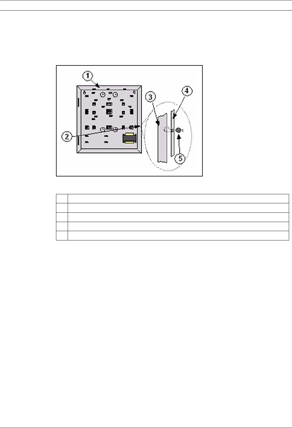
124 en | Agency Approvals and Requirements Easy Series
F01U087835 | 02 | 2008.10 System Reference Guide Bosch Security Systems, Inc.
Seal the Enclosure
1. Open the pre-opened hole which is on the right of the enclosure.
2. Pass the sealing wire through this hole, and bring the two wires in the corresponding
hole of the enclosure door.
3. Seal the sealing lead as near as possible from the enclosure.
Figure 12.1 Enclosure Sealing
1Enclosure
2 Sealing Location (pre-opened)
3 Right side of the enclosure
4 Right side of the door
5Sealing lead

Bosch Security Systems, Inc.
130 Perinton Parkway
Fairport, NY 14450
(800) 289-0096
www.boschsecurity.com
© Bosch Security Systems, Inc., 2008
